

Page 1

SIGRAND
SHDSL modem
Sigrand SG-16B
User's Guide
v. 2.5
Novosibirsk
2006
1
Page 2

© 2005, 2006, Sigrand LLC
All trademarks and registered trademarks mentioned hereinafter are the
property of their respective owners.
Contents
Contents page
How to use this Guide
1. Modem description
1.1 DSL interface specifications
1.1.1 Maximum reach performance
1.1.2 File transfer performance
1.2 Ethernet interface specifications
1.3 Ethernet Bridge specifications
1.4 RS-232C interface specifications
1.5 Power supply unit
1.6 Miscellaneous data
1.7 Shipment contents
1.8 Environmental specifications
1.9 Appearance, controls, indicators and connectors
1.9.1 Front panel and indicators
1.9.2 Rear panel and connectors
2. Modem setup directions
2.1 Connecting modem to a line
2.1.1 Requirements to a communication line
2.2 Choosing modem management method
2.3 ”Master”/”slave” mode
2.4 Setting DSL rate
2.4.1 Setting DSL rate for remote modem
2.4.2 Rate selection guidelines
3. Modem management via console port
3.1 Terminal setup
3.2 General purpose commands
The help command
2
Page 3

The info command
The stat command
The default command
The reboot command
3.3 DSL interface management
The help dsl command
The dsl command
3.3.1 “Master”/”slave” mode selection
The dsl master and dsl slave
commands
3.3.2 Setting DSL rate
3.3.2.1 Setting DSL rate from “master” modem
The dsl rate command
3.3.2.2 Setting DSL rate manually both sides
3.3.3 Line coding selection
The dsl code command
3.3.4 Link statistics
The dsl stat command
The dsl stat reset command
3.3.5 How to force a retrain
The dsl retrain command
3.4 Ethernet interfaces management
The eth help commands
The eth command
3.4.1 Rate and duplex type
The eth auto, eth /auto, eth
rate, eth half, eth full commands
3.4.2 Flow control
The eth flow and eth /flow
commands
4. Updating built-in modem firmware
Warranty and scope of liability
Appendix I
Appendix II
3
Page 4

How to use this Guide
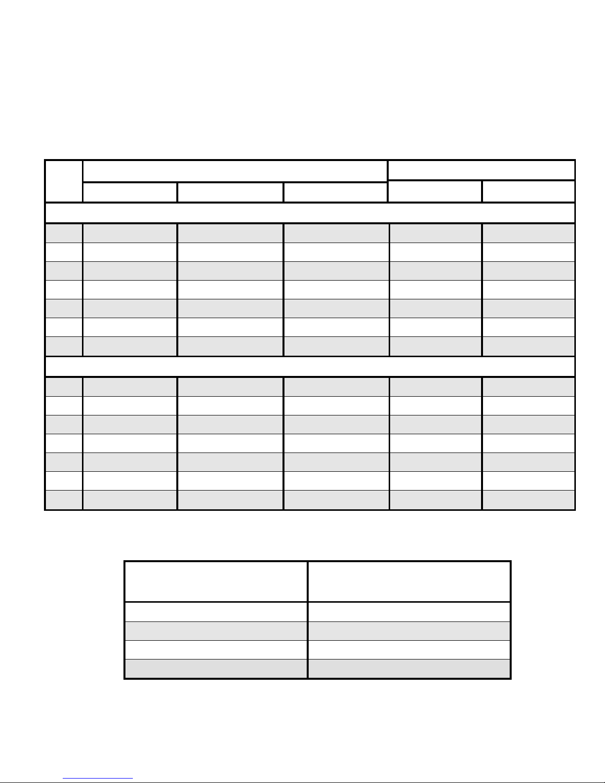
To ease using this Guide the following notational conventions are provided
here (icons as well as relevant fonts):
Icons
Icon Meaning Explanation
Pay attention!
The text marked by this icon
contains information making easy
setup and maintenance of
equipment
Important
information!
The text marked by this icon
contains important information
explaining details of operation of
equipment or software. This
allows to save your time and
efforts while equipment setup.
Do not make this!
Knowing this information allow
you to avoid actions that can
cause damage to hardware
and/or personal injury.
4
Page 5

Font usage
Designation Explanation
Picture on the screen
This font shows contents of
terminal screen while modem
setup.
Name of keyboard button
This font shows computer
keyboard buttons, e.g. ”Enter”,
which are used in the console
management mode.
Select Property in the File
menu
Italic notes the fragments of this
Guide containing important
information (together with the
relevant icons). It also marks
software buttons of menu in the
text.
dsl stat
Bold font is used to designate
modem management commands
during a terminal session.
Before starting installation of the modem we
recommend you to look for an updated version of this
User's Guide as well as the firmware and the drivers
available at our site www.sigrand. com
5
Page 6

1. Modem description
The Sigrand SG-16B modem is a SНDSL-modem. It features an Ethernetbridge and is designed to connect distributed local area networks as well as
remote computers and other devices equipped with an Ethernet interface.
The bridge can transmit VLAN IEEE 802.1Q tagged packets through the DSL
interface and the Ethernet interfaces.
The SHDSL interface of the modem conforms to ITU-T G.991.2.bis standard
and uses ТСРАМ (Trellis-Coded Pulse Amplitude Modulation) line coding.
Features of the ТСРАМ line coding:
The ТСРАМ line coding used by G.991.2 (G.SHDSL) compatible modems has
a few modes. The modes differ in complexity of coding algorithm. The modes
with larger number of modulation positions (ТСРАМ16, ТСРАМ32) are
applicable for higher rates, the modes with less number of modulation
positions (ТСРАМ4, ТСРАМ8) are applied for lower rates. Respectively, the
more complicated the coding algorithm the worse the channel noise immunity
and vice versa.
So take special attention to the ТСРАМ line coding algorithm selection while
configuring the line rate. It may be necessary to change the line coding to
achieve the best result.
Table 1 shows the line coding options and respective data rate ranges.
Table 1
Line coding Data rate range (kbps)
TCPAM32 256 – 6016
TCPAM16 192 – 3840
TCPAM8 192 – 1216
TCPAM4 64 – 704
Manual line coding selection is available only in the console
management mode – see chapter 3 of this Guide
6
Page 7

Compatibility:
The Sigrand SG-16B modem line coding is compatible with all Sigrand SG-16
series and Granch SBNI16 series modems.
Limitations of compatibility:
Interoperability with the Granch SBNI16 modems is
supported only within the compatible data rate range from
64 to 4608 kbps.
The modem features the following interfaces:
• one SHDSL interface (conforms to ITU-T G.991.2.bis standard) providing
the data rate range from 192 to 5696 kbps and the optional extended
range from 64 to 6016 kbps
• two Ethernet 10/100Mb (IEEE 802.3) interfaces with Auto-Negotiation and
Auto MDI/MDI-X
• one EIA-232C (RS-232C) interface for modem management.
1.1 DSL interface specifications
Link type point-to-point
Number of wires per line 2 (one pair)
Permitted cabling any UTP
Line coding TCPAM
Input/output impedance, Ω
135
Data rate range, kbps 64-6016
Data rate step, kbps 64
Transmission type full duplex
Data transfer mode synchronous, by packets
Packet type HDLC
Checksum type CRC32
Connector type RJ-45
Galvanic decoupling transformer
breakdown voltage, min, V
1500
Surge protector triggering voltage
(differential), V
30
7
Page 8

Arrester breakdown voltage (commonmode), V
350
1.1.1 Maximum reach performance
Brief information about the maximum reach performance of the Sigrand SG-
16B modem is shown on Table 2. The Bit Error Rate (BER) at the maximum
reach is equal to or less than 10-7. The specified reach is proved by testing at
the Sigrand lab reference line. Full version of the rate table is available at our
site www.sigrand.com. An actual reach may vary against the shown data due
to variations of cable performance.
Table 2
Data rate
(kbps)
Line coding
Rating TPP50-0.4
cable
(26 AWG)
TPP50-0.5
cable
(24 AWG)
6016 ТСРАМ32
Length (km/ft)
1.8/3500 2.2/7200
R (Ω)
476 420
4608 ТСРАМ32
Length (km/ft)
2.0/6500 2.6/8500
R (Ω)
560 455
3072 TCPAM16
Length (km/ft)
3.0/9800 4.2/13700
R (Ω)
840 736
2304 TCPAM16
Length (km/ft)
3.8/12400 5.4/17700
R (Ω)
1064 945
1536 TCPAM16
Length (km/ft)
4.4/14400 6.4/20100
R (Ω)
1232 1120
1024 TCPAM8
Length (km/ft)
5.0/16400 7.6/24900
R (Ω)
1400 1330
512 TCPAM8
Length (km/ft)
5.8/19000 9.0/29500
R (Ω)
1624 1575
256 TCPAM8
Length (km/ft)
6.6/21600 10.0/32800
R (Ω)
1848 1750
8
Page 9

128 TCPAM4
Length (km/ft)
7.4/24200 11.4/37400
R (Ω)
2072 1995
64 TCPAM4
Length (km/ft)
7.4/24200 11.4/37400
R (Ω)
2072 1995
1.1.2 File transfer performance
Performance of the SG-16B modem during file transferring by FTP protocol is
shown on Table 3. The table contains average readings obtained on a line
with error rate less than 10-7.
Table 3
Line data
rate
(kbps)
File transfer
performance
(KBps)
Line data
rate
(kbps)
File transfer
performance
(KBps)
6016 700 1792 209
5696 662 1536 179
4608 536 1280 149
4096 478 1024 119
3584 418 768 89
3072 354 512 59
2560 304 256 29
2304 261 192 22
2048 234 128 15
1.2 Ethernet interface specifications
Interface type 10/100 Base-T
Number of ports 2
Data rate, Mbps 10/100
Duplex type Half and full duplex
Compatibility ANSI/IEEE Std 802.3
Auto MDI/MDI-X available
9
Page 10

1.3 Ethernet Bridge specifications
MAC-address table size 2048
Maximum packet size, bytes 1536
Packet buffer size, KBytes: 512 (340 packets)
1.4 RS-232C interface specifications
Baud rate 9600, 57600
Protocol parameters 8-N-1
Flow control N/A
Connector type RJ-45 (DB-9F with converter)
1.5 Power supply unit
Type BPN-12-1V
Input voltage 220V/50Hz
Output voltage 12V
Maximum load current 1A
Polarity of central contact of connector positive
1.6 Miscellaneous data
Overall modem dimensions:
height, mm/in. 45/1.77
• width, mm/in.
225/8.86
• depth, mm/in.
165/6.5
Weight, g/lb 450/1
Weight with PSU, g/lb 1025/2.26
Power consumption, W 6
1.7 Shipment contents
10
Page 11

Sigrand SG-16B modem 1 pc.
Power supply unit 1 pc.
Guide 1 pc.
Cable with converter RJ-45-DB-9 1 pc.
Package 1 pc.
1.8 Environmental specifications
The modem is designed to operate under office conditions as follows:
air temperature 10 .. 40 °C (50 .. 104 °F)
relative air humidity up to 85 %
atmosphere pressure 84 .. 107 kPa (630 .. 802
mmHg)
1.9 Appearance, controls, indicators and connectors
The Sigrand SG-16B modem should be connected either to a computer
equipped with an Ethernet or Fast Ethernet card or to an Ethernet-switch.
We recommend to connect the modem to an Ethernet switch,
not a hub, since our equipment is optimized for interaction with
Ethernet switches.
The modem is manageable by switches placed on the rear panel as well as by
console management port (ch. 4.1). To manage the modem as well as to
monitor its status you should have an ANSI-compatible terminal emulation
software installed on your computer. Configure your terminal program
according to ch. 1.3 of this Guide.
1.9.1 Front panel and indicators
The front panel indicators display the status of device operation.
11
Page 12

Figure 1
Purpose of Sigrand SG-16B indicators
Table 3
Indicator Status Explanation
POWER
POWER
On Modem is on
Off Modem is off
ETHERNET ( channels 1 and 2)
LINK
On Valid Ethernet link detected
Off Ethernet link not detected
Blink Traffic exchange
100M LINK on
On 100Base-TX link detected
Off 10Base-TX link detected
FD/C LINK on
On Full duplex
Off Half duplex
Blink Collision detected
DSL
LINK
On Active link to remote modem
Off No link to remote modem
SNR
LINK on
Blink Bad Signal/noise ratio
Off Good Signal/noise ratio
LINK off
Blink Link activation in progress
Off No link
ERR
LINK on
Blink A packet with error received
Off No error
LINK off On Fatal error
12
Page 13

1.9.2 Rear panel and connectors
Layout of connectors and switches on the rear panel of the Sigrand SG-16B
modem
Figure 2
Purpose of connectors and switches of the Sigrand SG-16B modem
Table 4
Power supply unit plug
9-12V DC
RS-232C console port for modem management
RS232
DSL line connector
DSL
Terminal to connect to protective ground
PGND
Dial to select fixed rate for DSL channel
RATE
DIP switches to set up modem operation mode
SET
Ethernet 10/100Base-T socket 1
ETH1
Ethernet 10/100Base-T socket 2
ETH2
Fig. 3
The “RATE” dial and the “SET” DIP switches (fig.3) specify operation mode of
the DSL channel. The dial sets DSL channel data rate (fig.4).
13
Page 14
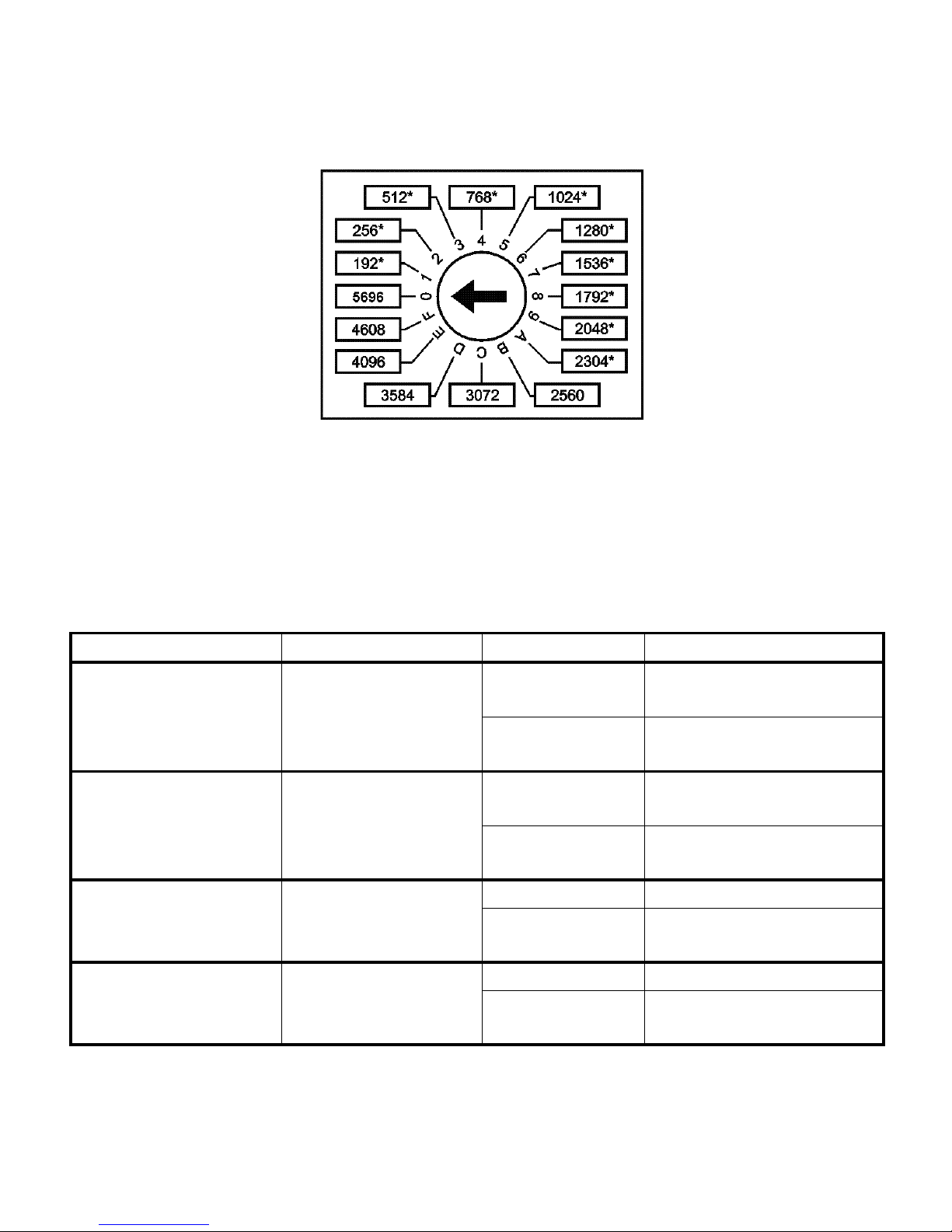
Fig. 4
The “SET1” DIP switch selects “Master/Slave” mode, the “SET2” switch
defines a method of the DSL channel rate negotiation and the “SET4” switch
sets a mode of modem management. Purpose of the switches are shown on
Table 5.
Table 5
Switch Purpose Position Meaning
SET1
Operation
mode
ON
Master modem
(STU-C)
OFF
Slave modem
(STU-R)
SET2
Local or
Preactivation
rate select
ON Rate is exchanged
by Preactivation
OFF Rate is set locally
on each modem
SET3
RS-232C
console port
baud rate
ON 57600 bps
OFF
9600 bps
SET4
Modem
management
method
ON by console port
OFF by DIP switches
14
Page 15

Attention!
Reboot the modem to activate a new modem operation
mode, changed by the DIP switches!
2. Modem setup directions
2.1 Connecting modem to a line
Make sure the line has no foreign devices varying its
specifications such as fuses, inductors, load coils and
other similar line conditioning devices. These devices
may cause serious modem performance limitations or
even completely prevent operation of an xDSL modem!
Make sure that the communication line in use has
neither external voltage supply nor attached foreign
telco devices! Ignoring this rule may cause permanent
damage to both the modems and those foreign telco
equipment!
2.1.1 Requirements to a communication line
The line must comply with the following requirements for proper operation and
performance:
• It must have neither leakage to ground nor to other wires (both connected
and loosed). It should not have taps (branches).
• Both wires must belong to the same twisted pair if a multi-pair cable is
used.
• Parallel connection of a few pairs (e. g., to reduce the line resistance) is
not permitted.
Ignoring the aforementioned requirements may cause significant modem
performance limitations or even completely prevent operation of an xDSL
modem.
15
Page 16
After you verify that the line comply with the aforementioned requirements -
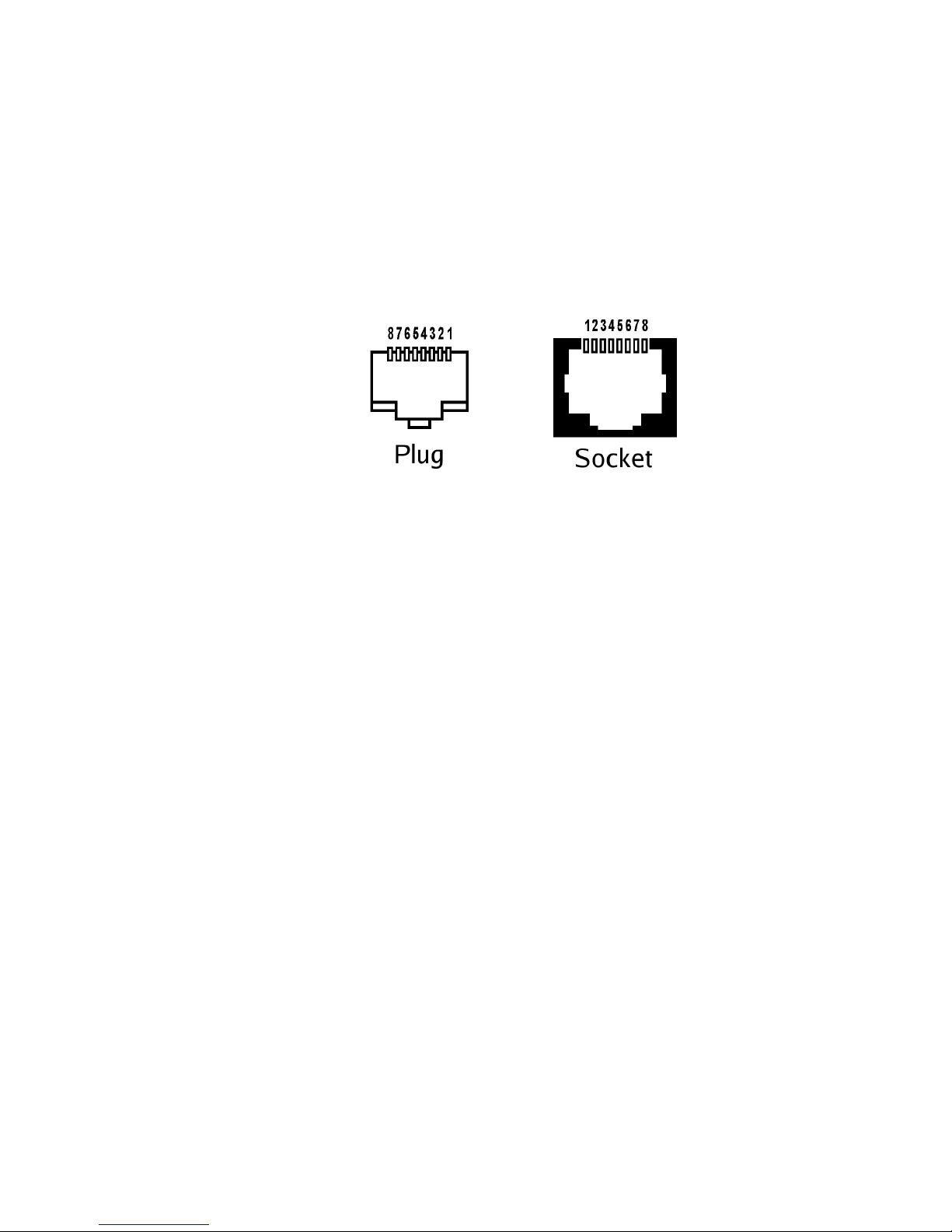
• Fix the supplied RJ-45 plug on the cable in accordance with figure 5. The
Sigrand SG-16B modem uses only one pair of pins, namely 4 and 5.
Other pins are not assigned.
• Attach the cable to the DSL connector of the modem.
Fig.5
2.2 Choosing modem management method
There are two ways to manage the modem:
• by the DIP-switches placed on the rear panel of the modem (see
fig.4);
• by a terminal program via the RS-232C console port.
Both modes have certain advantages over each other so a user is free to
choose either setup mode according to actual requirements for modem
operation.
Setup by switches is described here as the most simple method. Management
by a terminal program is described in Chapter 3.
To use setup by switches, set the SET4 switch to OFF state. For quick
reference use the sticker at the bottom side of the modem enclosure.
2.3 ”Master”/”slave” mode
Two modems operating peer-to-peer must be configured by the SET1 DIP
switch (fig. 3, table 4) such as one modem is set up as a “master” (SET1 is
ON) and another one as a “slave” (SET1 is OFF). We recommend to use as a
“master” the modem which is more accessible for management and
maintenance.
16
Page 17

2.4 Setting DSL rate
Fixed rate value is set by dial switch RATE (figures 2 and 4). One of 16 fixed
data rates have to be selected by the dial.
2.4.1 Setting DSL rate for remote modem
This feature is available only for modems with firmware version 2.5 or higher.
The SET2 switch has the following meaning:
• if SET2 is OFF, the rate is set manually at both ends of the line. (I
this case modem uses Annex A for compatibility with firmware
version 2.4 and lower)
• if SET2 is ON, the DSL rate is set by the dial switch RATE of the
“master” modem. (In this case Annex F is used.)
The SET2 switch must be set to the same position for both modems.
To operate properly peer-to-peer, the modems settings should
match each other! Do not forget to configure the remote
modem beforehand!
2.4.2 Rate selection guidelines
Before setting the data rate you should have known the performance of the
line the modems are intended for. If the line performance is unavailable, apply
the following technique to select the proper data rate:
• Measure resistance of the line. To do this, make short-circuit on either
line side and attach an ohmmeter to another one. Then determine a
maximum rate providing reliable communication by table 2.
• Switch carefully the dial to the required position with a screwdriver.
Reboot both modems to activate the new settings. If the remote rate
setting is used (SET2 is ON), change the “master” modem rate only. Link
activation takes up to 2 or 3 minutes to succeed.
• If the link is not activated (the DSL LINK LED is not getting light) during
the mentioned time, set a smaller value on the rate dial and do the next
attempt to activate the link.
17
Page 18

• If you can't get the link activated, consider to use console management
mode (Chapter 3). In this mode you can try to succeed by varying the
line coding (Chart 1) as well.
3. Modem management via console port
The modem is manageable by a terminal attached to the RS-232C console
port or by a computer with any applicable terminal emulation software.
3.1 Terminal setup
Set the the SET4 DIP-switch to “ОN” position to manage the modem through
the console port. (see Table 5, Figure 2).
Set the baud rate of the modem console port by the SET3 switch. SET3 is
OFF stands for 9600 baud, SET3 is ON stands for 57600 baud.
Attach the RS-232C port to a serial port of your computer by the supplied
cable.
Configure the terminal emulation software installed on your computer (for
example, HyperTerminal) as follows:
Data bits: 8
Parity: None
Stop bits: 1
Flow control: None
Baud rate (Bits per second) should be set to 9600 or 57600 in accordance
with SET3 switch setting.
Power on or reboot the modem. If the terminal has been set up properly, the
following message appears on the screen:
Sigrand SG-16B SHDSL modem V.2.5
Interface module ETH1/ETH2
Initialization complete
:
18
Page 19

3.2 General purpose commands
The modem is managed by a set of commands conventionally divided into two
types: the “general purpose” commands such as help, info, update,
default, reboot, and the interface management commands such as dsl
and eth1/eth2.
Capabilities of the console management mode allow to configure the DSL
interface as well as to control the Ethernet interfaces. It is also possible to
watch status of the interfaces, etc. The summary of the general management
capabilities can be invoked by the help command:
: help
**** Available commands: ****
HELP - display this text
HELP [ETH|DSL|PORT|E1|FXS|FXO] - detailed interface help
INFO - view information about hardware and firmware
STAT [RESET] - show all statistics (or clear it)
ETHx - view or change ETHx settings, x=1,2 (see HELP ETH)
DSL - view or change DSL settings (see HELP DSL)
PORT - view or change PORT settings (see HELP PORT)
E1 - view or change E1 settings (see HELP E1)
FXSx - view or change FXS settings, x=1,2 (see HELP FXS)
FXOx - view or change FXO settings, x=1,2 (see HELP FXO)
UPDATE - update sg16 firmware
DEFAULT - set factory defaults
REBOOT - reboot the modem
:
The SG-16 modems are multi-functional devices with various
types and combinations of system interfaces such as Е1,
V.35, FXO/FXS. Therefore the help command displays
commands for each interface available in this firmware.
The info command displays information about the firmware version, the
modem uptime, and current status of the modem interfaces.
19
Page 20

: info
Sigrand SG-16B SHDSL modem V.2.5
Setup mode: Terminal
SHDSL firmware: V.5.3E
FPGA configuration: V.2.20
Interface module ETH1/ETH2
Uptime: 0 days 01:08:55
ETH1: Rate=100 Mbit/s Duplex=FULL Auto-Neg FlowCont - OFFLINE
ETH2: Rate=100 Mbit/s Duplex=FULL Auto-Neg FlowCont - OFFLINE
DSL: CFG=PREACT Rate=192 Code=TCPAM16 MASTER Annex=F - OFFLINE
:
The stat command displays current status and statistics of the modem
interfaces:
: stat
ETH1: Rate=100 Mbit/s Duplex=FULL Auto-Neg FlowCont - OFFLINE
TX=0 RX=0 ERR=0 COL=0
ETH2: Rate=100 Mbit/s Duplex=FULL Auto-Neg FlowCont - OFFLINE
TX=0 RX=0 ERR=0 COL=0
DSL: CFG=LOCAL Rate=5696 Code=TCPAM32 MASTER Annex=A - OFFLINE
TX=0 RX=0 ERR=1 LOSW=0 CRC6=0 RETRAIN=0 of 1
Total online time: 0 days 00:00:00
Total offline time: 0 days 00:00:28
Connect duration: 0 days 00:00:00
:
The default command resets all modem settings to factory default values.
: default
Load factory default and reboot? (y/n) Y
Default settings loaded
Rebooting…
20
Page 21

entering cancel N or any other character except Y breaks the command
execution and causes the prompt to enter a next command.
The reboot command performs reset of the modem.
: reboot
Rebooting...
Sigrand SG-16B SHDSL modem V.2.5
Interface module ETH1/ETH2
Initialization complete
:
The update command is used to update the modem firmware. Detailed
procedure of firmware reprogramming is discussed in chapter 4 of this Guide.
Not recognized commands causes appearance of the message
Unknown command, illegal command options causes appearance
of the message Unknown keyword.
3.3 DSL interface management
We advise to invoke the help dsl command in advance to get informed
about the DSL management features available through the console
management mode:
: help dsl
DSL - show current DSL settings
DSL CFG [LOCAL|PREACT] - configuration mode: Local or G.hs
Preactivation
DSL RATE [rrrr|AUTO] | CODE cccc | MASTER | SLAVE - set mode for
DSLx
DSL ANNEX [A|B|F|G] - set Annex type
DSL STAT [RESET] - show statistics for DSL (or clear it)
DSL RETRAIN - force DSL to retrain
:
21
Page 22

The DSL command allows to view statistics, to enter or to change settings of
the DSL interface.
The command invoked with no option displays current settings of the interface
: dsl
DSL: CFG=PREACT Rate=192 Code=TCPAM16 MASTER Annex=F – OFFLINE
:
3.3.1 “Master”/”slave” mode selection
Configure one peer modem as “master”, do another one as “slave” for proper
operation.
This is performed by the dsl command with the master or slave options:
: dsl master
DSL: CFG=LOCAL Rate=512 Code=TCPAM8 MASTER Annex=A - OFFLINE
: dsl slave
DSL: CFG=LOCAL Rate=512 Code=TCPAM8 SLAVE Annex=A – OFFLINE
:
3.3.2 Setting DSL rate
Modems with firmware version 2.5 or higher have the ability to set DSL rate
from a “master” modem. The ability to set the rate manually at the both ends
of the line is supported as well.
3.3.2.1 Setting DSL rate from “master” modem
In order to control the rate by accessing the “master” modem only, configure
both modems beforehand for Preactivation (dsl cfg preact) and Annex F
(dsl annex f):
: dsl cfg preact annex f
DSL: CFG=PREACT Rate=2304 Code=TCPAM16 MASTER Annex=F - OFFLINE
:
22
Page 23

The rate setup is performed by the RATE rrrr option (“rrrr” stands for
rate in kbps). The rate is within 192 to 5696 kbps range with 64 kbps step:
: dsl rate 192
DSL: CFG=PREACT Rate=192 Code=TCPAM16 MASTER Annex=F - OFFLINE
: dsl rate 5696
DSL: CFG=PREACT Rate=5696 Code=TCPAM32 MASTER Annex=F – OFFLINE
:
To set a new value of the rate, enter the command at the “master” modem
only. The “slave” modem obtains the rate via G.hs Preactivation (ITU-T
G.994.1) protocol.
3.3.2.2 Setting DSL rate manually both sides
If the lower rates (64 to 128 kbps) or the higher rates (5696-6016) are
required, set the local control mode (dsl cfg local) for both modems. The
Annex type can be set A or F, if both modems have firmware version 2.5 or
higher. If one of the modems have firmware version 2.4 or lower (including
Granch SBNI16 modems), only Annex A should be used for compatibility (dsl
annex a).
: dsl cfg local annex a
DSL: CFG=LOCAL Rate=5696 Code=TCPAM32 MASTER Annex=A - OFFLINE
:
Manual rate setup is performed by the RATE rrrr option (“rrrr” stands for
rate in kbps). The rate is within 64 to 6016 kbps range with 64 kbps step. The
rate should be set the same for both sides:
23
Page 24
: dsl rate 6016
DSL: CFG=LOCAL Rate=6016 Code=TCPAM32 MASTER Annex=A - OFFLINE
: dsl rate 64
DSL: CFG=LOCAL Rate=64 Code=TCPAM4 MASTER Annex=A - OFFLINE
:
The line coding mode is also changed accordingly upon the rate change. See
how rates match line coding on Chart 1.
3.3.3 Line coding selection
As mentioned above, different TСРАМ line coding modes are used to transmit
data with different rates.
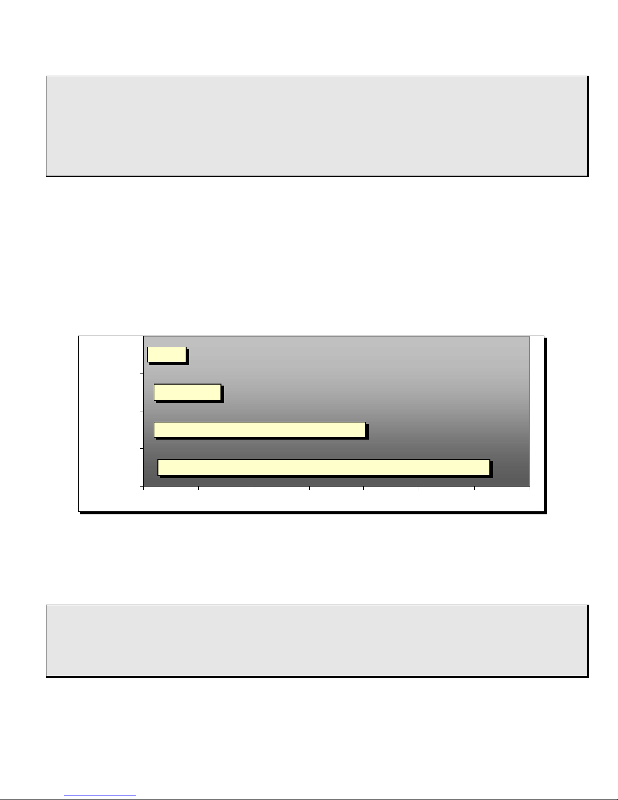
Chart 1
256 Kbps
192 Kbps
192 Kbps
64 Kbps
6016 Kbps
3840 Kbps
1216 Kbps
704 Kbps
0 1000 2000 3000 4000 5000 6000 7000
TCPAM32
TCPAM16
TCPAM8
TCPAM4
The code cccc option of the dsl command provides a way to select a line
coding mode of 4 available (ТСРАМ32, ТСРАМ16, ТСРАМ8 and ТСРАМ4). It
allows to select a proper mode in according to ratings of the line.
: dsl code tcpam8
DSL: CFG=LOCAL Rate=512 Code=TCPAM8 MASTER Annex=A – OFFLINE
:
24
Page 25

As follows from Chart 1, many data rates allows to use multiple
line coding modes. Rule: apply a coding mode with less positions
(ТСРАМ8, ТСРАМ4) on a line exposed to high level of noise;
apply a coding mode with more positions (ТСРАМ32, ТСРАМ16)
if bandwidth is limited.
In the local configuration mode (CFG=LOCAL) all four variations of the line
coding are applicable. In the Preactivation mode (CFG=PREACT), only two
codings can be used: TCPAM16 in the 192 to 3840 kbps range and TCPAM32
in the 768 to 5696 kbps range.
If the data rate is not within the permitted range for an entered line coding
mode, the following message appears: invalid line code for this
rate.
3.3.4 Link statistics
Use the dsl command with the stat option to view link statistics:
: dsl stat
DSL: CFG=LOCAL Rate=512 Code=TCPAM8 SLAVE Annex=A - ONLINE
TX=1341 RX=1231 ERR=1 LOSW=12 CRC6=11 RETRAIN=2 of 5
Loop Loss: 0.0 dB Noise Margin: +22.0 dB
Total online time: 0 days 00:42:19
Total offline time: 0 days 00:18:02
Connect duration: 0 days 00:15:53
:
Legend:
ONLINE – the DSL link is activated;
OFFLINE – the DSL link is not activated;
TX – the number of transmitted packets;
RX – the number of received packets;
ERR – the number of received packets with errors;
LOSW – the number of frame synchronization loss events;
CRC6 – the number of CRC6 checksum errors;
25
Page 26

RETRAIN – the number of successful attempts to establish the link with regard
to the total number of attempts;
Loop Loss – loop loss (attenuation level), dB;
Noise Margin – loop noise margin, dB;
Total online time – total time elapsed when link is on;
Total offline time – total time elapsed when link is off;
Connect duration – duration of the last successful session;
Use the dsl command with the stаt reset option to clear the statistics
counters:
: dsl stat reset
DSL: CFG=LOCAL Rate=512 Code=TCPAM8 SLAVE Annex=A - ONLINE
TX=0 RX=0 ERR=0 LOSW=0 CRC6=0 RETRAIN=0 of 0
Loop Loss: 0.0 dB Noise Margin: +22.0 dB
Total online time: 0 days 00:00:00
Total offline time: 0 days 00:00:00
Connect duration: 0 days 00:00:00
:
3.3.5 How to force a retrain
Retraining of the DSL interface is performed by the dsl command with the
retrain option:
: dsl retrain
DSL: CFG=LOCAL Rate=512 Code=TCPAM8 SLAVE Annex=A – OFFLINE
:
3.4 Ethernet interfaces management
The Sigrand SG-16B modem features two Ethernet 10Base-T/100Base-T
ports with Auto MDI/MDI-X.
26
Page 27

The following commands allow to manage the ports:
: help eth
ETHx - show current ETHx settings, ETHx=1,2
ETHx RATE [10|100]|FULL|HALF|[/]AUTO|[/]FLOW - set mode for
ETHx
ETHx STAT [RESET] - show statistics for ETHx (or clear it)
:
The eth command allows to view statistics, to enter or to change Ethernet
interface settings.
The command requires to specify interface index – eth1 stands for the
Ethernet1 interface and eth2 the Ethernet2 interface. The command entered
with no arguments allows to view current settings of the interfaces:
: eth1
ETH1: Rate=10 Mbit/s Duplex=HALF Auto-Neg FlowCont – ONLINE
:
3.4.1 Rate and duplex type
The modem Ethernet interfaces have Auto-Negotiation and flow control
settings enabled by default.
Transmission rate and duplex type are detected automatically in AutoNegotiation mode. The priority of operation mode detection descends from
100Base-TX Full Duplex (the highest priority), 100Base-TX Half Duplex,
10Base-T Full Duplex down to 10Base-TX Half Duplex (the lowest priority).
To disable the Auto-Negotiation mode use the eth1 or the eth2 commands
with the /auto option:
27
Page 28

: eth1
ETH1: Rate=100 Mbit/s Duplex=FULL Auto-Neg FlowCont – ONLINE
: eth1 /auto
ETH1: Rate=100 Mbit/s Duplex=FULL FlowCont – ONLINE
:
If Auto-Negotiation mode is off, use either the eth1 or the eth2 commands
respectively with the rate 10 or the rate 100 options to set the Ethernet
interface rate manually:
: eth1 rate 100
ETH1: Rate=100 Mbit/s Duplex=FULL FlowCont – ONLINE
: eth1 rate 10
ETH1: Rate=10 Mbit/s Duplex=FULL FlowCont – ONLINE
:
Also the full or the half options of the commands allows to switch
between full and half duplex, use the options on the relevant interface:
: eth1 half
ETH1: Rate=10 Mbit/s Duplex=HALF FlowCont – ONLINE
: eth1 full
ETH1: Rate=10 Mbit/s Duplex=FULL FlowCont – ONLINE
:
Use the eth1 or the eth2 command with the auto option to enable AutoNegotiation mode:
: eth1
ETH1: Rate=10 Mbit/s Duplex=FULL FlowCont – ONLINE
: eth1 auto
ETH1: Rate=100 Mbit/s Duplex=FULL Auto-Neg FlowCont – ONLINE
:
28
Page 29

3.4.2 Flow control
Besides setting of the rate and the transmission mode, the modem features
flow control in compliance with the IEEE 802.3x specifications. It improves
operation, protects packet buffer against overflowing and prevents data loss.
This technique may also improve total network throughput and help to achieve
optimal performance.
Use the eth1 or the eth2 commands with the flow option to enable flow
control feature:
: eth1 flow
ETH1: Rate=100 Mbit/s Duplex=FULL Auto-Neg FlowCont – ONLINE
:
Use the eth1 or the eth2 commands with the /flow option to disable the
feature:
: eth1 /flow
ETH1: Rate=100 Mbit/s Duplex=FULL Auto-Neg – ONLINE
:
29
Page 30
4. Updating built-in modem firmware
Use the update command to update the built-in firmware of the Sigrand SG16B modem in the following order:
: update
Load new image? (y/n) Y
Upon entering procedure acknowledgement Y the memory buffer is clearing
and the prompt to download the image file appears here:
Clearing buffer memory... OK
Loading image...
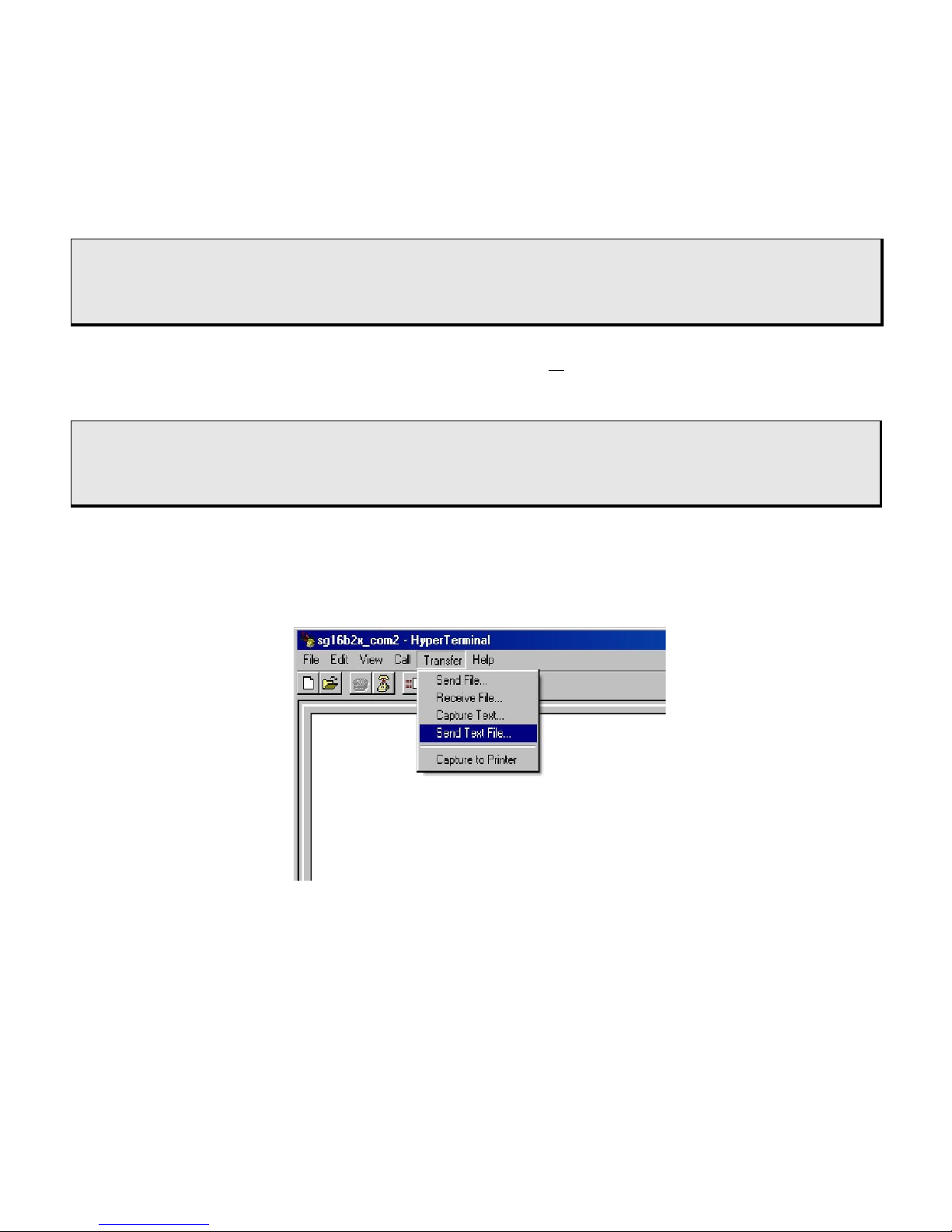
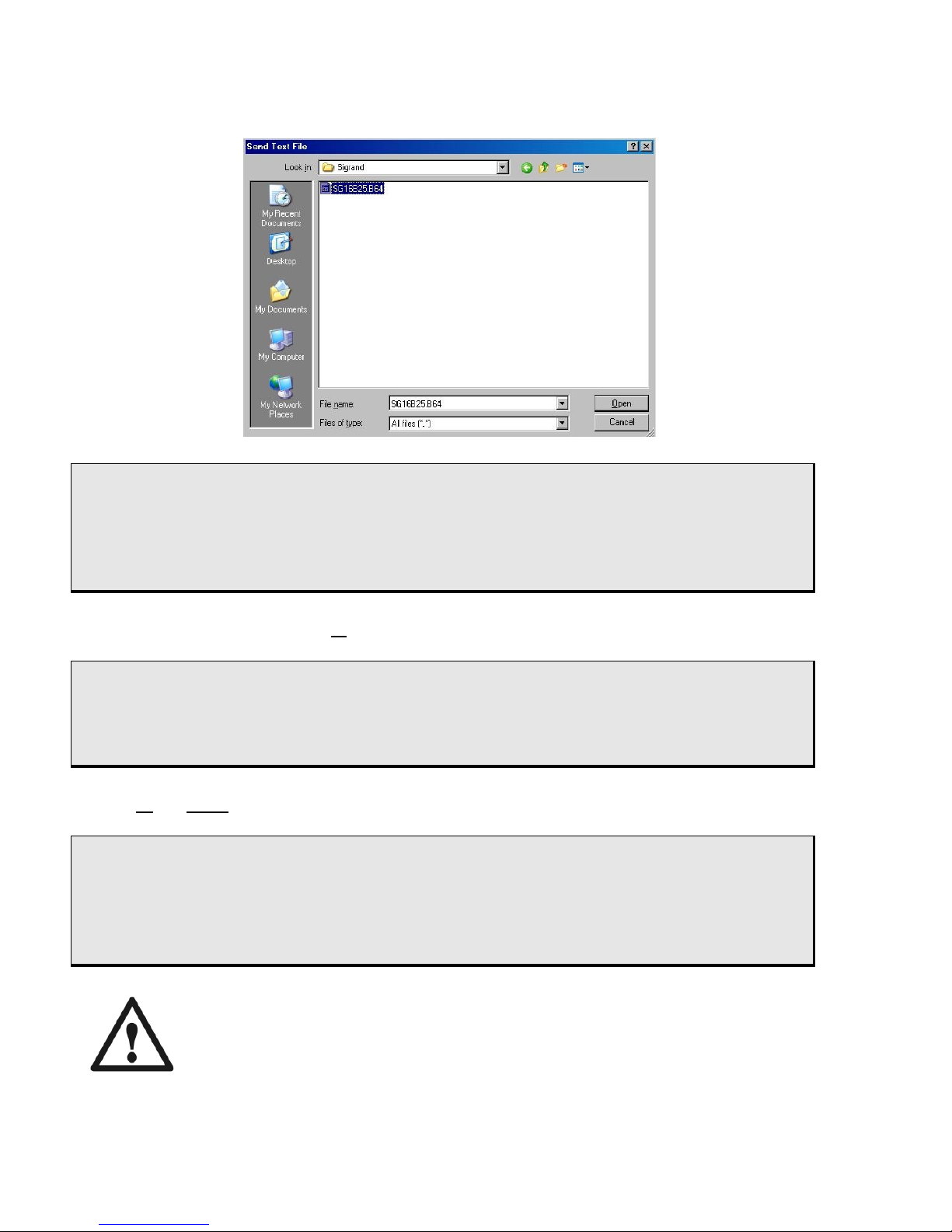
Then select the “Send Text File” option in the Send menu of the terminal
program (here we suppose you are using HyperTerminal from standard
Microsoft Windows shipment),
then specify location of the image file planned to load to the modem. Image
files look like *.b64. Since the firmware can contain a few image files, the
update procedure has to be performed for each file. Order of file updating may
be arbitrary.
30
Page 31
Clearing buffer memory... OK
Loading image... OK
Checking image... OK, Type=SG16HOST V.2.5
Program new image? (y/n) Y
Enter acknowledgement Y to complete the write procedure:
Checking BootLoader... OK
Self-Programming... OK
Rebooting...
press N or Esc as a response to any prompt to cancel the update procedure:
: update
Load new image? (y/n) N
Update canceled!
:
Reboot the modem when the firmware has been
updated!
31
Page 32

Warranty and scope of liability
The Manufacturer warrants its Modem to be free from defects in materials and
workmanship. This warranty applies only if the Purchaser has been used and
maintained the Modem in accordance with the operating and maintenance
directions given in this Guide. This warranty does not apply if the Modem has
been subject to misuse, negligence, accident, fire or other casualty.
This warranty is valid for a period of 5 (five) years from either the purchase
date as marked on the Warranty Coupon or the stated manufacturing date if
the purchase date has not been marked. Subject to conditions and limitations
set forth above and below, the Manufacturer will, at its option, either repair or
replace the Modem that prove defective of improper workmanship or
materials. The Manufacturer shall in no event be liable for any consequential,
indirect or damages or expenses, lost revenues, lost profits, or any other
incidental or consequential damages arising from the purchase, use or
inability to use the modem, even if the Manufacturer has been advised of the
possibility of such damages.
Warranty limitations:
Warranty is void for modems operating on wires having
aerial sections.
MANUFACTURER ADDRESS
Sigrand LLC
pr. Lavrentieva 6,
Novosibirsk,
Russia
Phones +7 (383)-330-02-43, 332-94-37 Fax +7 (383)-332-02-43
www.sigrand.com
32
Page 33

WARRANTY COUPON
For Sigrand SG-16B modem
Serial number _________________________________________
MFG date ____/____/200__
day month year
Quality checker_______________/_____________/
Stamp
Seller
Address
Phone
Sale date
Stamp
Signature
Purchaser
Address
Phone
Purchase date
Stamp
Signature
33
Page 34
Appendix I
General specifications of TPP cable
Table I.1 Frequency response for twisted-pair cabling with copper
conductor and PE-insulation (for reference only)
f,
kHz
Primary ratings
Secondary ratings
R~, Ω/km
L, H/km*10
-4
G,S/km*10
-4
|Z|, Ω α, dB/km
Conductor diameter 0.4 mm (26 AWG)
20 278 5.51 1.13 225.2 6.81
50 280 5.51 4.24 152.6 9.12
100 283 5.50 11.3 125.7 10.3
250 316 5.46 42.2 113.7 12.2
500 394 5.35 120 110.5 15.6
700 455 5.26 188 109.1 18.2
1000 535 5.15 305 107.7 21.7
Conductor diameter 0.5 mm (24 AWG)
20 181 5.50 1.13 185.1 5.15
50 182 5.50 4.24 133.3 6.48
100 189 5.49 11.3 118.0 7.17
250 234 5.40 42.2 111.6 9.21
500 310 5.23 120 108.8 12.4
700 361 5.26 188 107.4 14.6
1000 424 5.04 305 106.3 17.2
Table I.2 Cable loop resistance to conductor diameter ratio:
Conductor diameter
(mm)
Loop resistance
(Ω/km)
0.32 432
0.4 278
0.5 180
0.64 110
34
Page 35

Appendix II.
Configuring SG-16PCI
to interact with SG-16B
Proper operation of a SG-16PCI modem requires to set up the following
settings:
• Line Rate
• Line Code
• Operation mode (Master/Slave)
• HDLC Frame Options
Be guided by the relevant instructions when configuring the SG-16PCI modem
for different operating systems.
1. Line Rate
Use 64 step to change the rate when interact with a SG-16B modem.
Remember that changing the rate may also require to change the line coding
type (see Chart 1).
Set up the same rate on both the SG-16PCI and the SG-16B modems.
Current driver release does not support automatic rate selection (Line Probe)
for the DSL channel.
2. Line Code
To make interact the SG-16 SHDSL modems select line coding according to
the rate, Table 2 and Chart 1.
Set up the same line coding for both the SG-16PCI modem and the SG-16B
modem.
3. Operation mode (Master/Slave)
35
Page 36

Set up one modem as “Master” (or “STU-C”) and
another one as “Slave” (or “STU-R”).
4. HDLC Frame Options
Interaction between the SG-16PCI and the SG-16B SHDSL modems requires
to set up “CRC32/CRC16” to value “CRC32” and “Fill Byte Value” to value “All
bits are 1” on the SG-16PCI card.
36
 Loading...