


Desktop Vinyl Cutter
Users Manual

Bobcat Vinyl Cutter Index
Important Information ..................................................................................................I
Supplied Items ..............................................................................................................I
Chapter 1. Parts Names and Functions .....................................................................1-1
1.1 Front View ...................................................................................................1-1
1.2 Back View ....................................................................................................1-2
1.3 Side View……………………………………………………… .........................1-2
Chapter 2. Installation………………………………………………… ..............................2-1
2.1 Setting Up ....................................................................................................2-1
2.2 Connecting the Power Cable .......................................................................2-1
Chapter 3. Basic Operation .........................................................................................3-1
3.1 Blade Installation .........................................................................................3-1
3.2 Media Loading .............................................................................................3-3
3.3 DIP Switch Setting .......................................................................................3-5
3.4 Control Panel………………………………………………… ..........................3-7
3.5 Power On .....................................................................................................3-8
3.6 On/Off Line Key ...........................................................................................3-8
3.7 Pause Key ...................................................................................................3-8
3.8 Repeat Key ..................................................................................................3-9
3.9 Data Clear Key ............................................................................................3-9
3.10 Origin Setting .............................................................................................3-9
3.11 Tracking Performance ................................................................................3-10
3.12 Cut Test ....................................................................................................3-11
3.13 When Completing the Cutting Job .............................................................3-11
Chapter 4. Connecting the Cutting Plotter .................................................................4-1
Chapter 5. Basic Maintenance ....................................................................................5-1
5.1 Cleaning the Cutting Plotter .........................................................................5-1
5.2 Cleaning the Grid Drum ...............................................................................5-1
5.3 Cleaning the Pinch Rollers ..........................................................................5-1
Chapter 6. Troubleshooting .........................................................................................
6.1 What If the Cutting Plotter Cannot Operate .................................................6-1
6.2 Light Indicators ............................................................................................6-2
6.3 Cutting Plotter Quality Problems .................................................................6-4
Appendix:
A. Specification
B. Blade Specification
C. Quick Menu
D. Blade
Bobcat User’s Guide
6-1

IMPORTANT INFORMATION
Thanks for purchasing a Bobcat sign cutting plotter. For your safety and the optimization of
the machine, please read the following guide completely.
PRECAUTIONS IN USE
• Always hold the machine firmly from the bottom.
(0)
Hold from the bottom
Hold the depression area
(X)
• During the operation, keep your clothes and hair away from any moving parts of the
machine (such as the carriage and the drums).
• Connect the power cable to a grounded outlet.
• Always use the power cable from the accessory kits. Do not wire the power cable to
be bent.
• Do not connect the power cable to a branch outlet or an extension cable. There is
danger of overheating.
• Always put the pinch rollers within position of the white marks.
Checking Supplied Items
AC Power Card
RS-232 Printer
Cable
Cutting Strip
Blade
Error Correct &
Function Sticker
I
Safety Blade
Tweezers
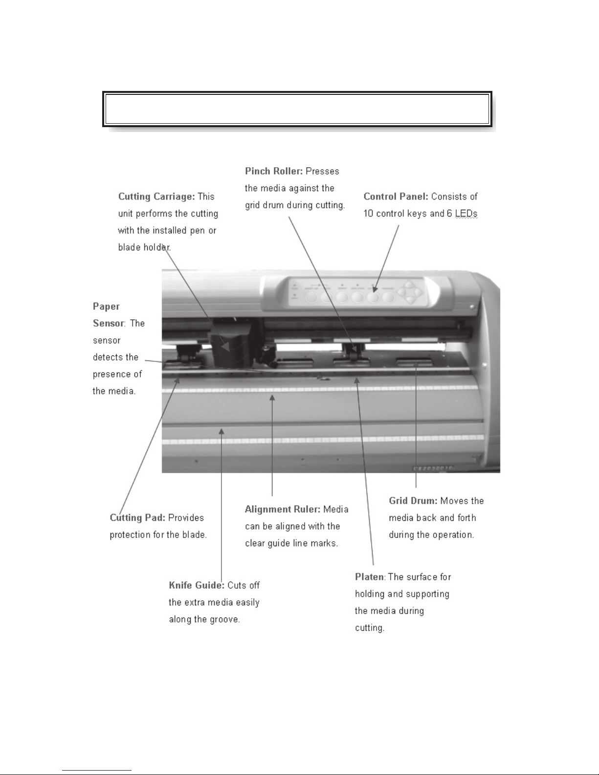
CHAPTER 1 Parts Names and Functions
1.1 Front View and Back View
1-1
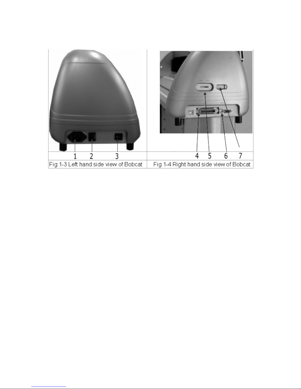
1.2 Side View
Left Hand Side (Figure 1-3)
1. AC Power Connector – Used to insert the AC power cord.
2. Fuse – Up to 3 Amp.
3. Power Switch – On when switches to [I]; Off when switches to [O]
Right Hand Side (Figure 1-4)
4. Parallel Interface Connector (Centronics) – Used to connect the cutting plotter to
a computer through a parallel interface cable.
5. Cutting Force Control Slider – Set the blade force here.
6. Serial Interface Connector (RS-232C) – Used to connect the cutting plotter to a
computer through a serial interface cable.
7. Dip Switch - Used for various parameter settings.
1-2

CHAPTER 2 Installation
2.1 Setting Up
Caution!
• There should be at least two people holding the machine from its left and
right bottom sides while unpacking, installing or relocating the cutting
plotter.
• Make sure the power switch is off before setting up the cutting plotter.
Notice ! Choosing a proper place before setting up the cutting plotter.
Select a proper location, which meets the following conditions:
• Operating Environment ~
Temperature: 5°C to 40°C (41 oF to 104 oF).
Humidity: 30% to 70%.
• Make sure that there is an adequate space around the cutting plotter so that
ventilation is not obstructed.
• Avoid unnecessary vibrations and set up your cutting plotter on a level surface.
• Please protect your machine from moisture, dust, draughts, and direct sun
light.
2.2 Connecting The Power Cable
Notice!
Make sure both the cutting plotter and the computer are turned off.
Plug the other end of the power cable into an electrical outlet of the correct voltage and with
proper grounding.
Step1
Connect one end of the cable to the interface connector on the left side of the cutting
plotter.
Step2
Connect the other end of the cable to your computer.
2-1
CHAPTER 3 Basic Operation
3.1 Blade Installation
Caution!
Do not touch the tip of the blade with your fi ngers.
Notice!
The blade will affect the cutting quality signifi cantly. If any of the following occurs,
which means the blade has reached the end of its life. Please replace with a new
blade.
1. The tip of blade is broken.
2. Cutting traces are not as good as they were.
3. Uncut area remains the same even the blade force has been raised
signifi cantly.
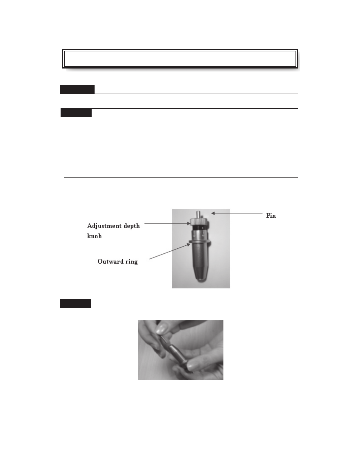
Figure 3.1.1 is the illustrator of the blade holder. Insert a blade into the bottom of
the blade holder and remove the blade by pushing the pin. Be sure to keep your
fi ngers away from the blade tip.
(Figure 3.1)
Step1
Install blade (Figure 3.1.1.1)
3-1
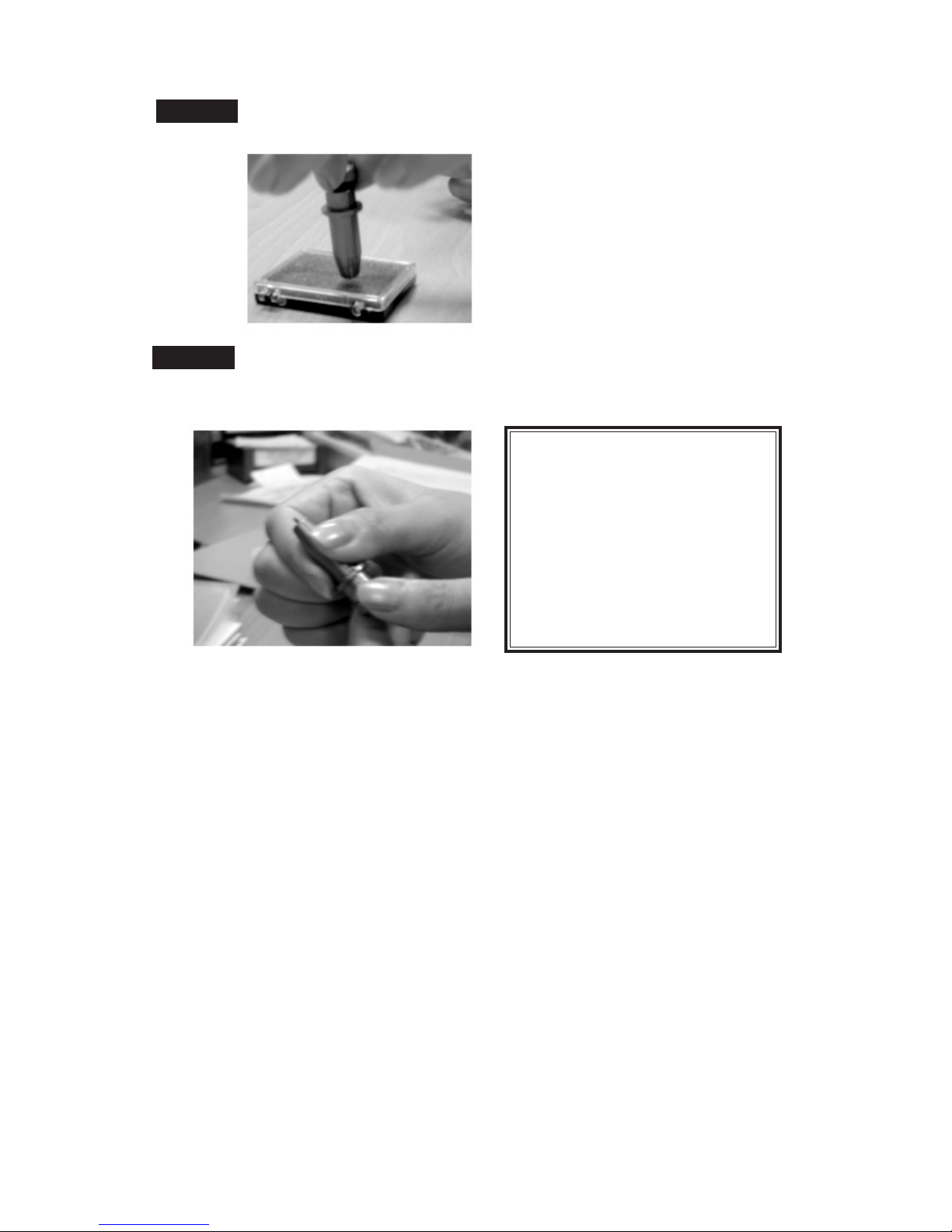
Step 2
Push the blade to the bottom of the blade holder. (Figure 3.1.2.1).
Figure 3.1.2.1
Step 3
Adjust the blade tip to suitable length by screwing “Blade tip adjustment screw”
clockwise or count-clockwise (Figure 3.1.3.1).
Tips:
“The proper length” means the
blade’s length is about 0.1mm more
than film’s thickness. For example, if
the thickness of film is 0.5mm, then
blade’s length is properly adjusted
to 0.6mm and it can completely
cut through the film layer but will
not cut though the paper backing
(See Appendix “D”).
Figure 3.1.3.1
3-2

3.2 Media Loading
3.2.1 Loading The Sheet Media
To load the media properly, please follow these procedures:
Pull the lever forward to raise the pinch rollers (Figure 3.2.1.1).
(Figure 3.2.1.1)
Load your media on the platen and slide it under the pinch rollers from either the front
side or the backside of the cutting plotter. The alignment rulers on the platen extension
will help you to adjust the media precisely.
Note:
Make sure that the media covers at least one of the paper sensors on the platen.
Once the media covers the sensor, the cutting plotter will start sizing the media
automatically.
3-3

3.2.2 Positioning The Pinch Rollers
Move the pinch rollers manually to the proper position. Make sure that the pinch rollers
are positioned above the grid drums. The white marks on the main beam will help you to
position the pinch rollers easily and correctly (Figure 3.2.2.1).
(Figure 3.2.2.1)
Push the lever backward to lower down the pinch rollers.
Turn on the power, and the carriage will measure the size of the media automatically. After
sizing, the cutting plotter will start to work.
Note:
Move the pinch roller by applying force at the rear portion of the pinch
roller support. Do not move it by holding the front rubber roller.
Figure 3.2.2.2 Correct way to move the pinch rollers
3-4

3.3 DIP Switch Setting
To get a perfect cutting job, you need the proper DIP Switch settings. The table below
shows the function list of each DIP Switch. The cutting plotter will act according to the
value settings of the DIP Switch every time when you press the ON/OFF LINE key.
**DIP Switch settings cannot be changed during the operation.
You can change the settings by pressing the PAUSE key or when the cutting plotter is in
the off-line condition. The default value settings are as shown on
Figure 3.3.1
Dip Switch Function Switch Down Switch Up Default Value
SW 1-3 Offset Value (Please refer to SW 1-3) 0.275 mm
SW-4 Media Weight
SW-5
SW-6 Smooth
SW-7 Auto Unroll Enable Disable Enable
SW-8 Media Type
Quality Draft Fine Fine
Light Heavy Light Media
Enable Disable Enable
Edge Single Edge
SW 1-3 : OFFSET SETTING
The first three DIP Switches represent 8 different blade offset value settings as below:
SW-4 : MEDIA WEIGHT (SPEED)
The fourth DIP Switch sets the maximum cutting speed. Heavy media has a smaller upper limit. The value of the cutting speed can be changed from the driver.
SW-5 : QUALITY
There is a trade-off between the cutting quality and the speed, the better the cutting quality,
the slower the cutting speed.
3-5

SW-6 : SMOOTH
Makes the curves smoother during cutting.
**When cutting smaller letters, please set the smooth disabled to cutting quality smooth
setting.
SW-7 : AUTO UNROLL
Unroll the heavy media at least 50 cm when the next point of movement is located beyond
the unrolled position.
If the media type is single, this function will be disabled.
SW-8 : MEDIA TYPE
When using a piece of media, set it to “ON”; and set it to “OFF” when using a roll of
media.
3-6

3.4 Control Panel
3-7

3.5 Power On
• Keep fingers away from the platen when the cutting
plotter is in operation.
• Keep loose clothing, hair, and any other items away from the grid
drum when the cutting plotter is in operation.
Turn on the power on the left side of the cutting plotter and the POWER LED will light up.
Notice: It will take about 10 sec. to initialize the machine; then the cutting plotter will be
ready to receive data from a computer. Refer to the following chart to understand what
represented by each light on the control panel.
3.6 ON/OFF LINE Key
**On line
When the machine is under the “ON LINE ” condition, the ON/OFF LINE LED lights up.
The cutting plotter is ready to receive data from the host computer. At this moment, only
“PAUSE” and “ON/OFF LINE” keys are valid.
**Change the setting value
1. Press the PAUSE key. Then switch the DIP to change the value settings.
2. Press the ON/OFF LINE key to valid the new settings and to continue cutting.
Note :
The parameters of the DIP Switch can not be changed while cutting unless you press
the “PAUSE” key. After pressing the “PAUSE” key, you can change the settings.
**Terminate the cutting & clear the data in the buffer
1. Press the ON/OFF LINE or PAUSE key
2. Then press the DATA CLEAR key
**Off - line
When the machine is in “OFF LINE” mode, the ON/OFF LED doesn’t light up. At this
moment, you can switch the DIP settings, make a plot test to adjust the cutting pressure
and set a new origin. Pressing the button again will let the cutting plotter switch back to
“ON LINE” condition, and resume the suspended operation. However, there might be
some data loss during this interruption.
3.7 PAUSE Key
The purpose of the “PAUSE” key is to temporarily terminate the motion of the cutting
plotter after it starts cutting. At this moment, the ON/OFF LINE LED is flashing; you can
change the DIP Switches settings and the cutting force. It will resume cutting after the
ON/OFF LINE key is pressed, to return the machine back to on-line status.
3-8

3.8 Repeat Key
You can cut your last cutting job at the same position by pressing REPEAT key without
setting a new origin.
** Procedures to repeat a cutting job at different positions:
1. After the cutting job is finished, use the ARROW keys to move the tool
carriage. Move the carriage to your desired position, and then press the
ORIGIN SET key. The ORIGIN SET LED lights, and the new origin point settles down.
2. Press the REPEAT key to repeat the cutting job, and the REPEAT LED lights.
3.9 Data Clear Key
The purpose of the DATA CLEAR key is to clear the data in the buffer memory. The
DATA CLEAR key can only works under the pause or off-line condition. The DATA
CLEAR LED lights during under the condition.
3.10 Origin Setting
Use the ORIGIN SET key to set a new origin at any position in the cutting area where the
tool carriage starts to work. Please note that the new origin setting must be made under
the off-line condition.
** Procedures:
1. After loading the media and lowering down the lever, use the ARROW keys to
move the carriage to the desired location to set a new origin.
2. Press the
ORIGIN SET key and the ORIGIN SET LED lights.
3-9

3.11 Tracking Performance
In order to achieve the best tracking performance for a long plot, we recommend
some significant media loading procedures described as followed:
1. If the media length is less than 4 mm, leave a margin of 0.5mm~15mm on the
left and right edges of the media (see Figure 3.11.1).
3.11.1
2. If the media length is longer than 4mm, leave at least 25mm margin on the left
and right edges of the media (see Figure 3.11.2).
3.11.2
3-10

3.12 Cut Test
Before carrying out an actual cutting, it is necessary to perform a cutting test to determine the
appropriate cutting force for your knife and media.
The cutting test should be repeated until you get an appropriate cutting condition.
Once you finish the cutting test, the new origin is set to the current tool carriage position.
**Procedures:
1. After sizing the media, press the ON/OFF LINE button to switch the condition to the off-line mode.
2. Then press the arrow buttons to move the tool carriage to the position where you want to make
the cut test.
3. Press the
CUT TEST key to make the cutting test. The CUT TEST LED lights up.
3.12.1 Adjust The Cutting Force
First, move the “Cutting Force Control Slider” to the minimum force, then increase the force
gradually by moving the slider, until an optimum force is obtained to cut through the media. When the
cutting test is completed, a square cut out appears. If the square can be easily peeled off from the
media, the setting of the cutting force is appropriate. If not, adjust the force again.
3.12.2 Adjust Offset Value
The square plot out should appear as one of the following figures:
AA BB CC
Appropriate offset value offset too low offset too high
Or Over-speed
If the square appears like the BB or CC layout, adjust the OFFSET setting (please refer to paragraph
SW1-3 OFFSET SETTING.
Note: The new origin will be set at the position of the tool carriage after the cutting test.
3.13 When Completing the Cutting Job
After the cutting is completed, raise the sheet loading lever, then remove the material from the machine. You can also cut off the extra media with the cutting plotter tool along the knife guide (Figure
3.13.1).
Figure 3.13.1
3-11

CHAPTER 4 Connecting the Cutting Plotter
The cutting plotter communicates with a computer through a Parallel port (Centronics) or
a Serial port (RS-232C). This chapter shows you how to connect the cutting plotter to a
host computer and how to set up the computer/cutting plotter interconnection.
4.1 PARALLEL TRANSMISSION
4.1.1 Connecting to the Parallel Port (Centronics)
1. Connect the parallel cable to the cutting plotter and the host computer
(Figure 4-1).
2. Set up the output port LPT1 or LPT2 from your software package
3. Send the data to your cutting plotter directly. Or, use DOS commands like
TYPE or PRINT to output the data.
4.2 SERIAL TRANSMISSION
4.2.1 Connecting to the Serial Port (RS-232C)
1. For PC users, please connect the RS-232C cable to the serial connector of the
assigned serial port (COM1 or COM2) of your host computer.
2. Set up the communication parameters (Baud Rate, Data Bits/Parity and Stop Bits) to
match the settings on the computer.
4-1

CHAPTER 5 Basic Maintenance
This chapter explains the basic maintenance (i.e. cleaning the cutting plotter) required for the cutting
plotter. Except for the steps mentioned below, all the other maintenances must be performed by a
qualifi ed service technician.
5.1 Cleaning the cutting plotter
In order to keep the cutting plotter under good conditions and have the best performance,
you need to clean the machine properly and regularly.
Precaution in Cleaning
• Unplug the cutting plotter before cleaning.
• Never use solvents, abrasive cleaners or strong detergents for cleaning.
They may damage the surface of the cutting plotter and the moving parts.
Recommended Methods
• Gently wipe the cutting plotter surface with a lint-free cloth. If necessary, clean with a water-
rinsed or an alcohol-rinsed cloth. Wipe the cutting plotter to remove any residues on the cutting
plotter. Finally absorb water with a soft, lint-free cloth.
• Wipe all the dust and dirt from the tool carriage rail.
• Use a vacuum cleaner to clean any accumulated dirt and media residue beneath the pinch roller
housing.
• Clean the platen, paper sensors and the pinch rollers with a water-rinsed cloth or alcohol-rinsed
cloth. Finally absorb water with a soft, lint-free cloth.
• Use the same method mentioned above to clean dust and dirt from the stand.
5.2 Cleaning the Grid Drum
• Turn off the cutting plotter, and move the tool carriage away from the area needed to be cleaned.
• Raise the pinch rollers and move them away from the grid drum for cleaning.
• Use a bristle brush (a toothbrush is also acceptable) to remove dust from the drum surface.
Please rotate the drum manually while brushing to clean the drum completely. Refer to Figure
5-1
5.3 Cleaning the Pinch Rollers
If the pinch rollers need a thorough cleaning, use a lint-free cloth or cotton swab to wipe away the
accumulated dust from the rubber portion of the pinch rollers. To prevent the pinch rollers from rotating while cleaning, use your fi ngers to hold the pinch rollers in place.
Please, use a lint-free cloth or cotton swab rinsed with alcohol to remove the embedded or persistent dust.
5-1

CHAPTER 6 Troubleshooting
This chapter helps you to correct some common problems you may come across. Prior to
getting into the details of this chapter, please be sure that your application environment is
compatible with the cutting plotter.
Note:
Before contacting your local dealer, please make sure that the problems are coming from
your cutting plotter, not from the communication between the computer and cutting plotter
or from a malfunction in your computer or software.
6.1 What If The Cutting plotter Cannot Operate?
If your cutting plotter doesn’t plot, please check the following items fi rst:
Is the power cord plugged in properly?
Is the power cord connected to the power connector properly?
Is the power switch turned on properly?
Solutions:
If the POWER LED lights on, the cutting plotter should be in a normal condition. Turn off
the cutting plotter and turn it on again to see if the problem still exists.
If the POWER LED doesn’t light, please call your local dealer to resolve this problem.
6.2 Light Indicators
Some of the operating problems can be identifi ed by the lights on the control
panel.
When your cutting plotter stops operating or the lights are on or fl ashing unexpectedly,
see the following descriptions of the panel light patterns and the actions you should
take.
6-1

6.2.1 Warning Indicators
When the ERROR LED flashes (as shown below), take the necessary actions according to the following
instructions. When the problems are solved, the ERROR LED will turn off automatically. Pressing the
ON/OFF LINE button can also turn off the ERROR LED.
Warning 1 The graph is clipped
This condition indicates that the cutting graph is bigger than the cutting area.
You can solve the problem by:
1. Reload a wider or longer media.
2. Move the pinch rollers to widen the cutting area.
3. Re-scale the graph to a smaller size. Then send the cutting job again from your
computer to the cutting plotter.
Warning 2 HPGL/2 command error
If the cutting plotter cannot recognize the commands from your computer, please check the commands
applied to your cutting plotter in the HP-GL/2 or HPGL commands. Then send the same job to the cutting
plotter again.
If that doesn’t solve the problem, please contact your local dealer.
Warning 3 Lever up or no media
Check that you have lowered the lever down and make sure that you load the media before cutting.
Warning 4 Cannot repeat cutting
There are two possibilities:
1. There is no data in the buffer: please send the job again from your computer;
2. The buffer is full: please send the same job from your computer again.
Under both conditions, press the ON/OFF LINE key to clear the warning message.
Warning 5 Communication error
Check that the serial/USB/parallel cable has been connected to the cutting plotter and computer
properly.
If so, then check whether the interface settings are correct. Check that the communication settings in
your PC are the same as the ones on your cutting plotter (for example – 9600bps, no parity, 8 bits, 1
stop bit. Then, press ON/OFF Line key to switch back to On Line mode.
Warning 6 Width sensor error
Check that the pinch rollers are positioned above the grid drum and reload the media again.
6-2

Note:
In order to identify the warning messages easily, please stick the warning sticker (in
accessory box) on the side cover of your cutting plotter.
6.2.2 Error Indicators
If some mechanical problems occur during the operation, the ERROR LED will turn on.
Please follow the instructions below to solve the problem. If the cutting plotter still cannot
work, please contact your local dealer and tell him or her about the error indicator.
Error 1 and 2
Please contact your local dealer to replace SRAM or DRAM.
Error 3 Check the media, drum or X-motor (Drum driven motor)
This message indicates that there might be a problem on the X-axis. Please check that
the drums are working normally and see that the media is well loaded. Then turn on the
power and reboot the cutting plotter.
Error 4 Check media, or Y motor (carriage driven motor)
This message indicates that there might be an obstruction to the carriage relating to a
problem on the Y-axis. Please clear the obstruction and check that the carriage can move
smoothly. Then turn on the power and reboot the cutting plotter.
6-3

6.3 Cutting plotter Quality Problems
6-4

Appendix A
Bobcat Specifications
Model Name/No. BA-60
Max. Cutting Width 590mm(23.23in)
Max. Media Loading Width 719mm(28.3in)
Min. Media Loading Width 124mm(4.88in)
Acceptable Material Thickness 0.8mm (0.03 in)
Number of Pinch Rollers 2
Motor DC Servo Control
Cutting Force 0~300 g
Max. Cutting Speed Up to 600 mm /sec. (23.62 ips)
Memory 16MB ( 4MB in buffer )
Interfaces USB 1.1 & Parallel (Centronics) & Serial
(RS-232C)
Commands HP-GL, HP-GL/2
Control Panel 10 Control Keys , 6 LED’s
Dimension (HxWxD) 220x 879x258mm
8.67 x34.61x10.16in
Net Weight 11.2kg
Power Supply AC 100-240V, 50~60 Hz (auto switching)
*This specification is subject to change without prior notice.

Appendix B
The Specification for GCC Blade
ZZ00219A
GCB-145S
ZZ00220A
GCB-245R
ZZ00221A
GCB-360SB
For cutting general signage vinyl. Blade with largest angle.
The blade is 45° with Yellow Cap, 0.25 mm blade offset
For cutting thick fluorescent and reflective vinyl. Also for cutting detailed work in standard vinyl.
The blade is 45° with Red Cap, 0.25 mm offset
For cutting reflective vinyl, cardboard, sandblast, flock, and
stencil sharp edge.
The blade is 60° with Green Cap, 0.50 mm blade offset
ZZ00222A
GCB-460SO
ZZ00233A
GCB-500
For cutting reflective vinyl, cardboard, sandblast, flock, and
stencil sharp edge.
The blade is 60° with Blue Cap, 0.25 mm blade offset
For Cutting small text and fine detail. Sharp blade with
smallest offset.
The blade is 0.175 mm blade offset with Black Cap

Appendix C
QUICK MENU
1. Power ON (The POWER LED lights on)
2. Note: Make sure the level is up before placing the media on the cutting plotter. Place
the media and pull the level to lower down the pinch rollers (must be sure the pinch
rollers are position above the grid drums, that is, within the white marks).
3. It will take about 10 sec. to initialize the machine. Then it will size the media
automatically according to the settings of the dip switch (usually the presetting is
EDGE media type).
4. Off-line condition – The cutting plotter is not ready to receive data from the computer.
Press ON/OFF LINE key, the LED above the key turns off.
5. On-line condition – The cutting plotter is ready to receive data from computer. Press
ON/OFF LINE key, the LED above the key lights.
6. Change the value settings during the cutting. Press PAUSE key, the LED above the
key flashes. Press ON/OFF LINE key to continue the cutting.
7. Terminate the cutting and clear the data in the buffer. Press ON/OFF LINE key or
PAUSE key and then press DATA CLEAR key.
Appendix D
About the Blade
Offset
OFFSET is the distance that the blade tip is displaced from the center line of the blade.
Protrusion Length of the Blade
Length of protrusion = t1 + t 2/ 2, but for your convenience you may just make it about
0.3~ 0.5 mm beyond the blade holder tip.
 Loading...