

Signtex Lighting Moonlite LED MHE-AC Series Installation Instructions & User Manual
Moonlite LED™
High Output Emergency Light
Installation Instructions & Users Manual
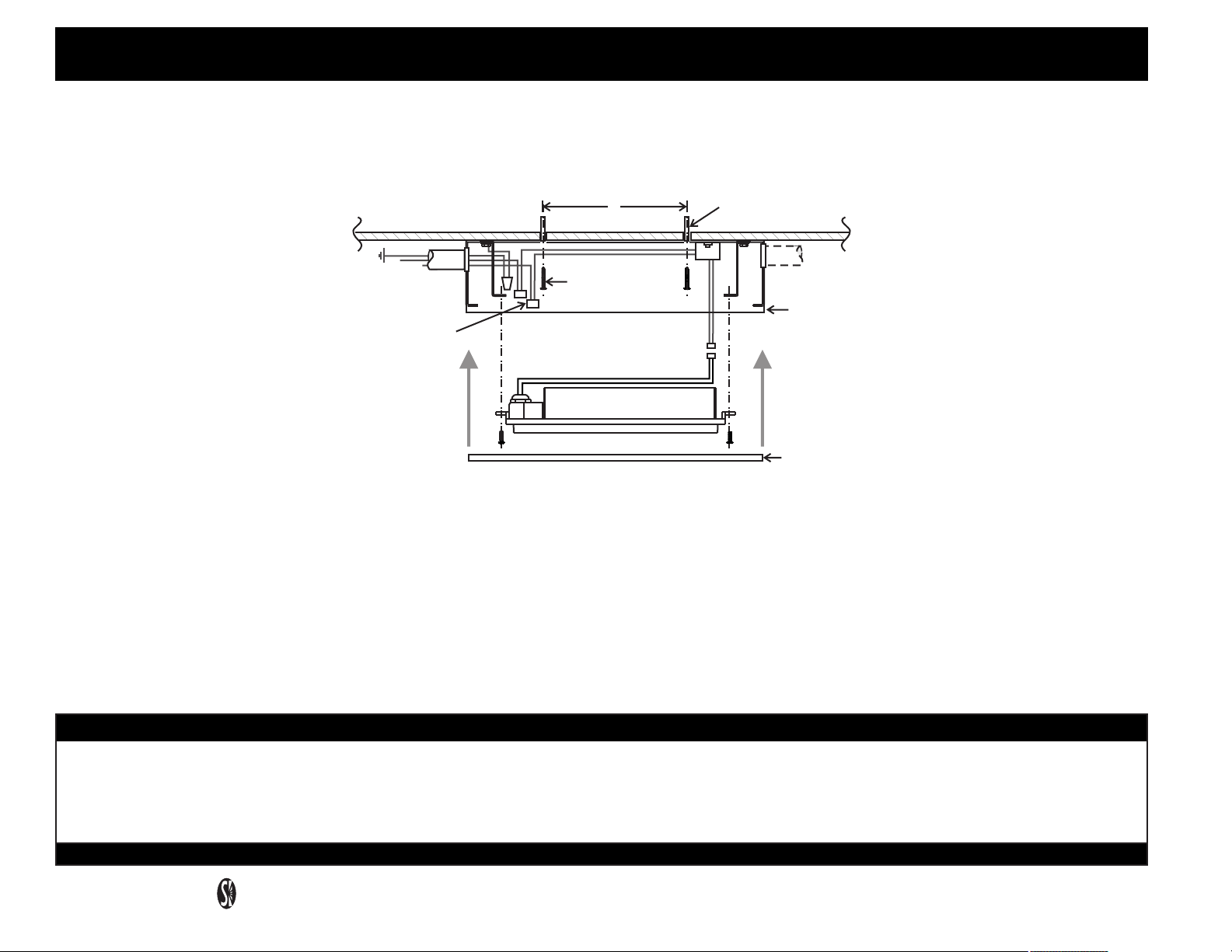
Fig. 1. DIRECT SURFACE MOUNT
Series MHE-AC
04.15.01
SCREW ANCHOR
(2 PLCS)
LAMP
HOUSING
COVER
120/ 277
VAC IN
CEILING
G
L
N
PUSH- IN
CONNECTORS
(SUPPLIED)
#12-22 AWG
8”
MOUNT SCREWS
(BY OTHERS)
LAMP
CONNECTOR
LAMP
ASSBY
1. See Fig 1. Identify mounting position on ceiling in accordance with fixture layout specifications, and install (2) screw anchors, minimum size
#10, at 8” between centers.
2. Insert small flat blade screwdriver or similar tool under notch at either end of cover, twist gently to release snap and lift cover. Unscrew (4) #8
lamp assembly screws, lift lamp assembly from Housing and disconnect lamp plug.
3. Mount housing to ceiling with (2) mount screws. Route 120/ 277 VAC IN/OUT wiring.
4. Connect wiring: BLACK- 120 VAC LINE
WHITE- NEUTRAL
ORANGE- 277 VAC LINE
GREEN- GROUND
5. Reconnect lamp plug and reinstall lamp assembly with (4) #8 screws, and replace cover. Supply power to check lamp operation.
IMPORTANT SAFEGUARDS READ AND FOLLOW ALL SAFETY INSTRUCTIONS
1. Disconnect AC power before servicing.
2. Refer to wiring diagram for proper connections.
3. All servicing should be performed by qualified personnel.
4. Consult your local building code for approved wiring and installation.
5. Do not use outdoors.
Signtex Lighting
220 VFW Avenue, Grasonville, MD 21638 P (410)827- 8300 F(410)827- 8866
6. Do not use this equipment for other than intended use.
7. Do not let power cords touch hot surfaces.
8. Mount and secure the fixture at a location and height to avoid ready access and tampering by unauthorized persons.
9. The use of accessory equipment is not recommended by the manufacturer and may cause an unsafe condition.
SAVE THESE INSTRUCTIONS
Moonlite LED™
High Output Emergency Light
Series MHE-AC
04.15.01
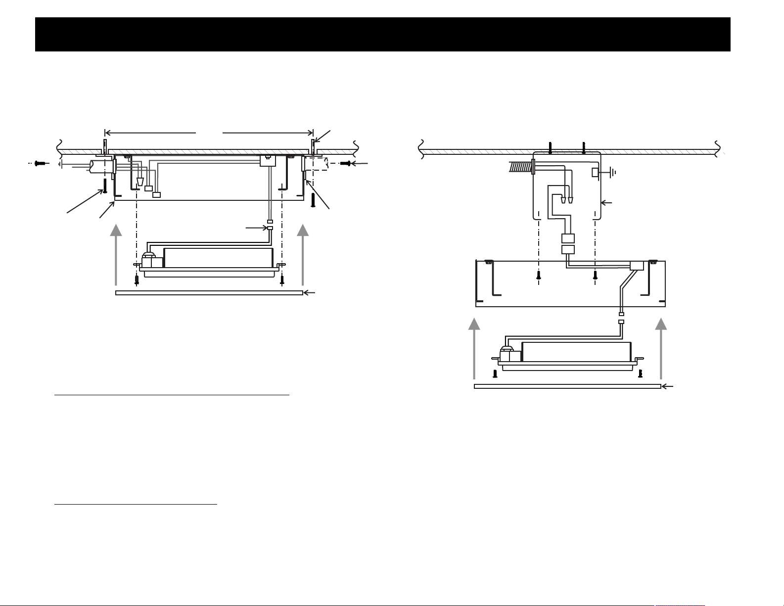
Fig. 2. SURFACE MOUNT WITH END BRACKETS Fig. 3. SURFACE MOUNT TO J-BOX
SCREW
ANCHOR
(4) SUPPLIED
BRACKET
SCREW
CEILING
120/ 277 VAC
IN/ OUT
GND
G
CEILING
L
N
15 1/2”
MOUNT
SCREWS
(2) REQ'D
LAMP
HOUSING
POLARIZED LAMP
CONNECTOR
LAMP
ASSBY
END BRACKET
(2) SUPPLIED
COVER
WB
POLARIZED LAMP
CONNECTOR
LAMP
ASSBY
J- BOX
4” x 4”
SURFACE MOUNT WITH END BRACKETS
1. See Fig 2. Install (2) screw anchors at 15 ½” centers.
2. Insert flat blade screwdriver under notch at end of cover, twist gently to release cover plate. Unscrew (4) #8 lamp assembly screws, lift lamp
assembly from Housing and disconnect lamp plug.
3. Attach end brackets with (4) #8 screws and nuts as shown, mount housing assembly to ceiling and route 120/77 VAC IN/OUT wiring into
housing.
4. Proceed as for STANDARD SURFACE MOUNT steps 4 - 5
COVER
SURFACE MOUNT TO J-BOX
1. See Fig 3. Install standard 4” J-box centrally above installation point as shown and secure to ceiling using appropriate screw anchors.
2. Route 120/ 277 VAC IN/OUT wiring into j-box.
3. Proceed as for STANDARD SURFACE MOUNT steps 4 - 5.
-2-
 Loading...