

Coverlite
Series CVRAC
Recessed Emergency Light
INSTALLATION INSTRUCTIONS
Series CVRAC
Recessed Emergency Light
INSTALLATION INSTRUCTIONS
Series CVRAC
Recessed Emergency Light
INSTALLATION INSTRUCTIONS
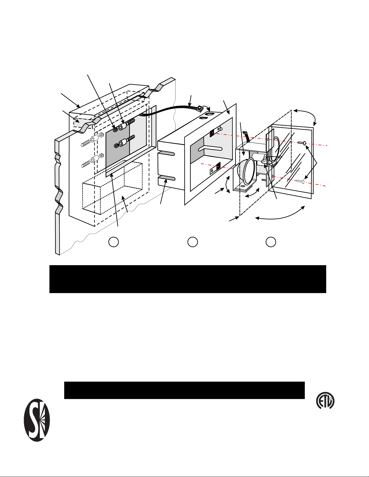
INSTALLATION INSTRUCTIONS
LAMP HOUSING NUTS (4 REQD.)
NYLON SPACERS (4 REQD.)
BACKBOX
CONTROL BOARD
Recessed Emergency Light
Series CVRAC
2 SNAP- IN
POLARIZED
CONNECTORS
LAMP HOUSING
SOLENOID
HIDDEN
MOUNT
SCREWS
2 REQD
FULLY ADJUSTABLE
ADJUSTABLE FOR
POWER
SUPPLY
PANEL CUTOUT 9" X 6"
PANEL THICKNESS
¼- 1½"
MR16 LAMP
ASSEMBLY
HINGED REFLECTIVE
DOOR ASSEMBLY
1 2 3
3 -STEP INSTALLATION
IMPORTANT SAFEGUARDS
READ AND FOLLOW ALL SAFETY INSTRUCTIONS
Before connecting to power supply, TURN OFF ELECTRICAL
POWER AT CIRCUIT BREAKER OR FUSE
Disconnect generator line AC power before servicing.
Refer to wiring diagram for proper connections.
All servicing should be performed by qualified personnel.
Consult your local building code for approved wiring and installation.
Do not use outdoors.
Do not use this equipment for other than intended use.
Suitable for indoor damp locations.
Do not let power cords touch hot surfaces.
Do not mount near gas or electric heaters.
Mount and secure the fixture at a location and height
to avoid ready access and tampering by unauthorized
persons.
The use of accessory equipment is not recommended by
the manufacturer and may cause an unsafe condition.
FLEXIBLE
DOOR LINK
DOORS
ADJUSTABLE
THRU 90°
SAVE THESE INSTRUCTIONS
Signtex Inc
LIGHTING
220 VFW Avenue, Grasonville, MD 21638
TEL: (410) 827-- 8300 Fax:(410)827- 8866
sales@signtexinc.com www.signtexinc.com
R
L
I
D
S
E
T
2003529
REV 03.11.1

TOP MOUNT
MOUNT BRACKET 4 SUPPLIED
Backbox Installation
Series CVRAC
BAR HANGER
(SUPPLIED
BY OTHERS)
CEILING
LAMP HSG
4 DROPWIRES
(MIN 20 lb LOAD)
MOUNT BRACKET
SCREW: 8 SUPPLIED
CEILING
15"-23"
B
PANEL CUTOUT
10"
B-CLIP
A
PANEL CUTOUT
CENTERED CUTOUT
12-48"
CENTER
HANGER
ALTERNATE
POSITION
10 1/2"
B-CLIP 4 SUPPLIED
MOUNT BRACKET
SCREW 8 REQD
7/8" K.O. 2 PLCS
LINE POWER 120 VAC
GENERATOR FEED 120 VAC
ROTATE B-CLIPS
90° TO FIT BAR
HANGERS AS
REQUIRED
1. For T-Bar installations, rotate side
bracket clips as required to fit T-Bar
hangers. For masonry ceilings, attach
side brackets to beam.
Refer to table on Page 2 and make
2.
cutout in ceiling panel.
PANEL THICKNESS
RANGE 3/8" - 1 3/8"
BACKBOX MUST BE FLUSH WITH
TOP (INSIDE) SURFACE. IN MASONRY
CEILINGS, SUPPORT WITH DROP
WIRES AND FRAMING AS REQUIRED
11 3/4"
15"-23"
CONTROL BOARD
24"-48"
B
BEAM CENTER
A
POWER SUPPLY
B-CLIP 4 REQD.
MOUNT BRACKET 4 REQD.
REV 03.11.1
-2-

Fig. 1
16" CRS
POWER SUPPLY
LAMP
1
LAMP
2
STUD OR
FRAME
CONTROL BOARD
Backbox Installation
Series CVRAC
3 3/8”
15 1/2"
LAMP HOUSING
TOP OR SIDE LINE
POWER 120 VAC
B
A
GENERATOR
FEED 120 VAC
WALL MOUNT
Backbox Installation
Series CVRAC
16" CRS
UPPER
MOUNT
BRACKET
PANEL
CUTOUT
LOWER
MOUNT
BRACKET
STUD OR
FRAME
UPPER
BRACKET
CONTROL
BOARD
CEILING
CONTROL BOARD
A
LAMP
1
POWER SUPPLY
B
LAMP
2
10"
STUD MT SCREWS 4 REQD.
(SUPPLIED BY OTHERS)
3 3/8”
B
TOP OR SIDE LINE
POWER 120 VAC
FEED 120 VAC
Fig. 1
LAMP HOUSING
11 3/4"
GENERATOR
15 1/2"
STUD OR
FRAME
BACKBOX
LENGTH
Backbox mounts to stud on either left or
1.
right side.
upper and lower mount brackets with (4)
#6-32 sheet metal screws provided.
2. See Table 1 below. Determine panel
cutout location desired. Place backbox into
position with face flush or just below stud
face. Mark mount bracket hole locations.
NOTE: Upper bracket holes should be a
minimum of 3" from upper joist or ceiling
panel.
3. Drill pilot holes in stud at marked
locations, and mount backbox in position
with (4) mount screws installed firmly.
Both upper and lower mount brackets
must be used. Fixture weight may be up
to 15 lbs.
Select side to mount and attach
Table 1
PANEL CUTOUT
BA
POWER SUPPLY
(2) TRANSFORMERS
(OPTION 277V)
Fig. 2
LOWER
BRACKET
15 1/2"
15 1/2"
-3-
9" 6"
REV 03.11.1
 Loading...