

Page 1
Rapier Accessible Exit Sign
Series RAE-REC
Remote From Central Battery System Series CBS
Installation Instructions & Users Manual
12.13.00
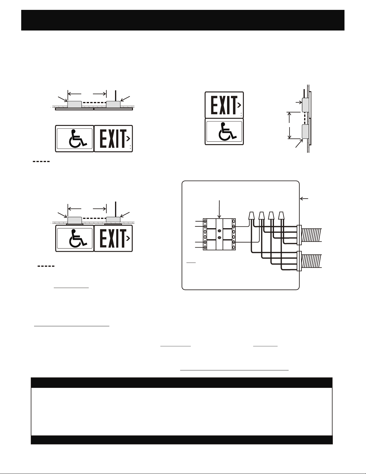
HORIZONTAL MOUNT SINGLE FACE
24 VDC
STANDARD
4" x 4" J- BOX
12 1/8"
REMOTE
INPUT
MASTER
STANDARD
4" x 4" J- BOX
Fig. 1
CLASS 2 LOW VOLTAGE WIRING 18-22 AWG
DOUBLE FACE
24 VDC
INPUT
STANDARD
4" x 4" J- BOX
ALL MODELS
EMERGENCY POWER RATING (EPR):
SINGLE FACE- 4 WATTS
DOUBLE FACE- 8 WATTS
12 1/8"
REMOTE
CLASS 2 LOW VOLTAGE WIRING 18-22 AWG
MASTER
STANDARD
4" x 4" J- BOX
VERTICAL MOUNT SINGLE FACE
STANDARD
4" x 4" J-BOX
8 1/4"
STANDARD
4" x 4" J-BOX
MASTER SIGN ASSEMBLY
PUSH- WIRE
TERMINAL BLOCK
G
W
KEY
G- GREEN: COMMON GND: 24 VDC NEG
W- WHITE: EXITS AND CVRE: 12-24 VDC POS
R- RED: EMERGENCY: 24VDC POS
B- BLACK: SECURITY / NIGHT OPS: 24 VDC POS
G
W
24 VDC
INPUT
Fig. 2
G
W
R
B
G
W
R
B
J-BOX
24 VDC
INPUT
CIRCUIT
24 VDC
OUTPUT
CIRCUIT
J-BOX INSTALLATION
1. See Fig 1: Install a 4” x 4" J-box for Master sign and a 4” x 4" J-box for Remote sign. Position J-boxes approx ¼”
below finished panel surface and set in line, 12 1/8” apart for horizontal mount, and 8 ¼” apart for vertical mount.
NOTE- Location of J- boxes must be accurate to position the two signs correctly.
2. See Fig 2: Attach low voltage input and output wiring to Terminal Block mounted on Master power supply assembly
(some fixtures may be shipped with wiring in place). Maintain color codes and polarities as shown.
IMPORTANT SAFEGUARDS READ AND FOLLOW ALL SAFETY INSTRUCTIONS
1. Disconnect AC power before servicing. 7. Do not let power cords touch hot surfaces.
2. Refer to wiring diagram for proper connections. 8. Mount and secure the fixture at a location and height
3. All servicing should be performed by qualified personnel. to avoid ready access and tampering by unauthorized
4. Consult your local building code for approved wiring and persons.
installation. 9. The use of accessory equipment is not recommended by
5. Do not use outdoors. the manufacturer and may cause an unsafe condition.
6. Do not use this equipment for other than intended use.
SAVE THESE INSTRUCTIONS
Page 2
Rapier Accessible Exit Sign
Remote From Central Battery System Series CBS
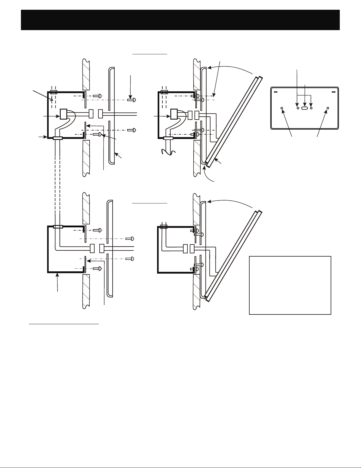
Single Face Wall Mount
Series RAE-REC
12.13.00
SEE FIG. 2
WIRING
DETAIL
PUSH- WIRE
TERMINAL
BLOCK
4" x 4" J- BOX
BY OTHERS
OUTPUT TO
REMOTE
MASTER
24 VDC
CIRCUIT
22 AWG
24 VDC
FROM
MASTER
#8-32 X 3/4"
BASE MOUNT
SCREWS
2 REQD
WHITE
GREEN
ADAPTOR PLATE
SCREWS
#8-32 (2 REQD)
CEILING OR
WALL PANEL
4" ADAPTOR
GREEN
WHITE
BASE
PLATE
REMOTE
BACKPLATE
MT. SCREWS #8-32
SIGN
ASSEMBLY
LOCATOR TAB
DRILL OUT 3/16" DIA
IN TWO PLACES TO
MATCH
ADAPTOR PLATE
REMOVE K.O.
FOR WIRING
BACKPLATE
RECOMMENDED:
DRILL 3/16" IN TWO PLACES
FOR ADDITIONAL WALL MT.
SUPPORTS
USING SCREW ANCHORS
(BY OTHERS)
WHITE
GREEN
HARDWARE KIT SUPPLIED
4" X 4"
J-BOX
CEILING OR
WALL PANEL
4" ADAPTOR
PLATE
(1) Two 4” ADAPTOR
(2) Four #8-32 x ¾”
(3) Wiring #22 AWG
(4) Push- In Terminal Block
PLATE
Machine Screws
GREEN and WHITE
SIGN INSTALLATION
1. Remove Base from Master and Remote signs and knock out or drill center wire access hole, and two holes 3/16” dia to match
2. Route GREEN and WHITE LED wiring through center hole of Base and attach to J-box adaptor plate with two #8-32 screws
3. If arrows are required, remove two lens clips in upper corners of sign assembly and loosen two #8 flat-head screws on lower
4. Raise sign assembly into position and insert two locator tabs on base of sign into slots provided in Base. With sign in open
5. Insert lamp plugs wire nuts into J-box cavity, ensure wiring is clear of sign housing, hinge faceplate into position and snap closed.
Adaptor Plate in J-box. It is recommended to drill two additional holes 3/16: dia for additional support using screw anchors in wall
surface.
supplied- do not over- tighten. Install optional screws as shown.
bracket. Lift out lens to access chevron arrow knockouts. Place housing face down on RAISED SCRATCH FREE SURFACE and
knock chevrons out with punch and light hammer. Slide lens under lower bracket and replace screws and clips.
position, connect GREEN and WHITE leads together with lamp plugs provided: MAINTAIN COLOR CODES.
-2-
Page 3
Rapier Accessible Exit Sign
Remote From Central Battery System Series CBS
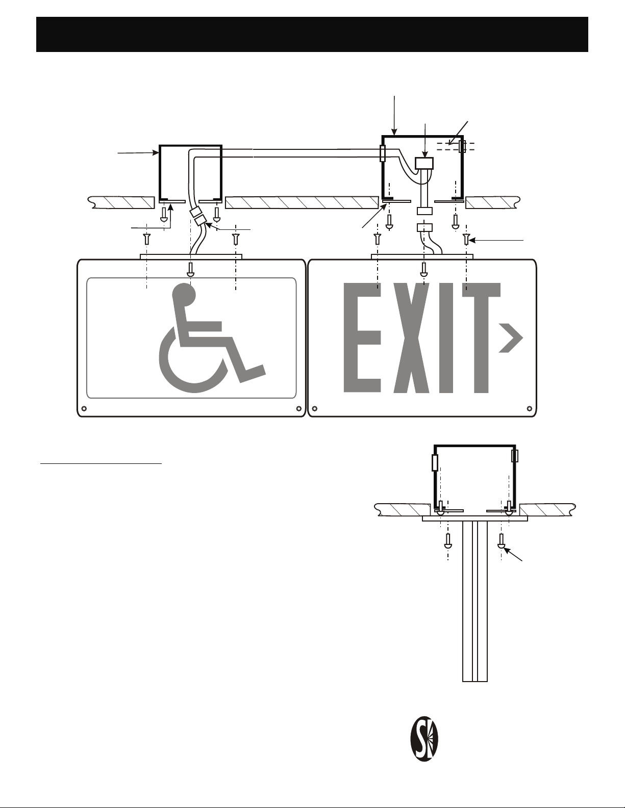
Double Face Top Mount
Fig. 3
FROM
4" x 4" J-BOX
BY OTHERS
MASTER
GREEN
WHITE
OUTPUT TO
REMOTE
18-22 AWG
12-24 VDC
4" X 4" J- BOX
BY OTHERS
PUSH- WIRE
TERMINAL
BLOCK
Series RAE-REC
12.13.00
SEE FIG. 2
WIRING
DETAIL
24 VDC
4" ADAPTOR
PLATE
LAMP PLUG
POLARIZED
3- PIN
4" ADAPTOR
REMOTE
SIGN INSTALLATION
1. Route low voltage output wires to remote J-box and install
push- wire terminal block and adaptor plate in Master J-box with
(2) #8-32 screws supplied.
PLATE
MASTER
CEILING
CANOPY SIGN
MOUNT SCREW
#8-32 X 3/8”
FLAT HD
2 REQ’D
PER SIGN
CEILING
2. Route lamp wiring through center hole in Canopy Plate and
attach Canopy to housings with (4) #8-32 x 3/8” Flat Head
screws supplied.
3. Raise sign assembly into position, maintain color codes and
connect GREEN and WHITE lamp wiring with 2- pin connectors
provided.
4. Insert lamp plug into J-box cavity, and secure sign assembly in
position with two color matched #8-32 x ¾” screws through
Canopy Plate into Adaptor Plate as shown.
-3-
CANOPY MOUNT
SCREW
#8-32 X 3/4”
COLOR MATCHED
2 REQ'D PER SIGN
Signtex Inc
LIGHTING
220 VFW Avenue, Grasonville, MD 21638
TEL: (410) 827-- 8300 Fax:(410)827- 8866
[email protected] www.signtexinc.com
 Loading...