

Page 1
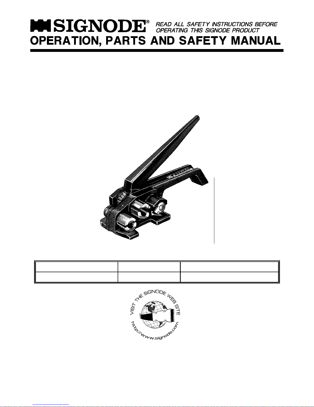
WTD-2 MANUAL STRAP TENSIONER
FOR USE WITH PLASTIC STRAPPING ONLY
Part No. 260060
STRAP TYPE WIDTH THICKNESS
Dymax, Contrax, Tenax 1/2"(12mm) .015"(0.38mm) to .030"(0.76mm)
IMPORTANT - DO NOT DESTROY THIS MANUAL. It is the customer's responsibility to have all operators
and service personnel read and understand this manual. Contact your local Signode representative for
additional copies of this manual.
© Copyright 2003, Signode 186125 Rev. 3/2003
TOOL SPECIFICATIONS
Page 2
READ THESE INSTRUCTIONS CAREFULLY. FAILURE TO FOLLOW THESE INSTRUCTIONS CAN RESULT
IN SERIOUS PERSONAL INJURY.
STRAP BREAKAGE HAZARD
Improper operation of the tool or sharp corners on the load
can result in strap breakage during tensioning, which could
result in the following:
!! A sudden loss of balance causing you to fall.
!! Both tool and strap flying violently towards your face.
Failure to place the strap properly around the load or an
unstable or shifted load could result in a sudden loss os strap
tension during tensioning. This could result in a sudden loss
of balance causing you to fall.
Use correct Signode products for your application. If you
need help contact your Signode Representative.
Signode tools and machines are designed and warranted
to work together with Signode strapping and seals. Use
of non-Signode strap and seals and/or manufactured or
specified replacement parts may result in strap breakage
or joint separation while applying strapping to a load or
during normal shipping and handling. This could result
in serious personal injury.
!! If the load corners are sharp use edge protectors.
!! Positioning yourself in-line with the strap, during
tensioning and sealing, can result in severe personal
injury from flying strap or tool. When tensioning or
sealing, position yourself to one side of the strap and
keep all bystanders away.
TRAINING
This tool must not be used by persons not properly trained in
its use. Be certain that you receive proper training from your
employer. If you have any questions contact your Signode
Representative.
EYE INJURY HAZARD
Failure to wear safety glasses with side shields
can result in severe eye injury or blindness.
Always wear safety glasses with side shields
which conform to American National Safety
Institute standard Z87.1 or Euro Norm 166.
FALL HAZARD
Maintaining improper footing and/or balance when operating
the tool can cause you to fall. Do not use the tool when you
are in an awkward position.
CUT HAZARD
Handling strap or sharp parts could result in cut
hands or fingers. Wear protective gloves.
SAFETY PROCEDURES FOR TOOL OPERATION
!! Before using this tool, read its Operation and Safety
Instructions contains in this manual.
!! Tuck strap end back into the dispenser when not in use.
JOINT FORMATION
Never handle or ship any load with improperly formed joints.
Misformed joints may not secure the load and could cause
serious injury. Follow the joint inspection procedures in each
sealers manual.
MOVING AND STACKING STRAPPED LOADS
Before moving or stacking any strapped load, follow all
standard industry practices regarding safe material handling
procedures.
CUTTING TENSIONED STRAP
Using claw hammers, crowbars, chisels, axes or simialr tools
will cause tensioned strap to fly apart with hazardous force.
Use only cutters designed for cutting strap. Read the
instructions in the cutter's manual for proper procedures in
cutting strap. Before using any Signode product read its
Operation and Safety Manual.
TOOL CARE
!! Inspect and clean the tool daily. Replace all worn or
broken parts.
!! Lubricate all moving parts weekly unless otherwise
specified.
WORK AREAS
Keep work areas uncluttered and well lighted.
Page 3
OPERATING INSTRUCTIONS
!! Wear safety glasses which conform to American National Safety Institute Standard Z87.1 or Euro Norm 166.
!! Stand to one side of the strap while tensioning. Make sure all bystanders are clear before proceeding.
!! Do not pull the tension handle to the rear while tensioning so as to contact the gripper cam. Doing so will cause the tensioned
strap to release.
!! Failure to follow the above could result in serious personal injury.
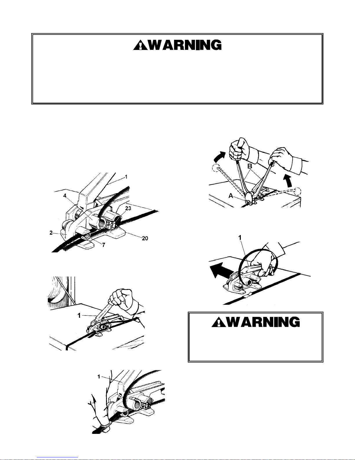
1. Place the strap around the package. Squeeze the tension
handle (1) against the tensioner frame (2), thus raising the
gripper (23). Insert the bottom strap between the
tensioner frame and under the cutter sleeve (7), also
between the gripper plug (20), and the gripper. Leave
approximately 3 inches of strap protruding from the front
end of the tool and release the tension handle (1).
2. Slide the top strap through the strap slots in the cutter
sleeve (7), and windlass (4). The strap is ready to be
tensioned.
3.
Stand to one side of the strap line and, while guiding the
strap and tool, operate the tension handle (1), back and
forth until the desired tension level is achieved.
5. Using the D-504 or D-506 sealer (A), with the handles (B),
in the fully open position, crimp the seal by placing the
jaws of the sealer over the seal and pushing the handles
together.
6. Fully squeeze the tension handle against the tensioner
frame, thus cutting the strap at the seal. While squeezing
the handle, slide the tool away from the completed tie.
4. When the desired tension is achieved, place the tension
handle in a rest position and
fit an open seal over
the top and bottom
straps.
NEVER HANDLE OR SHIP ANY LOAD WITH
IMPROPERLY FORMED JOINTS. Misformed joints may
not secure the load could cause serious personal injury.
Follow the joint inspection procedures in each sealer’s
manual.
Page 4
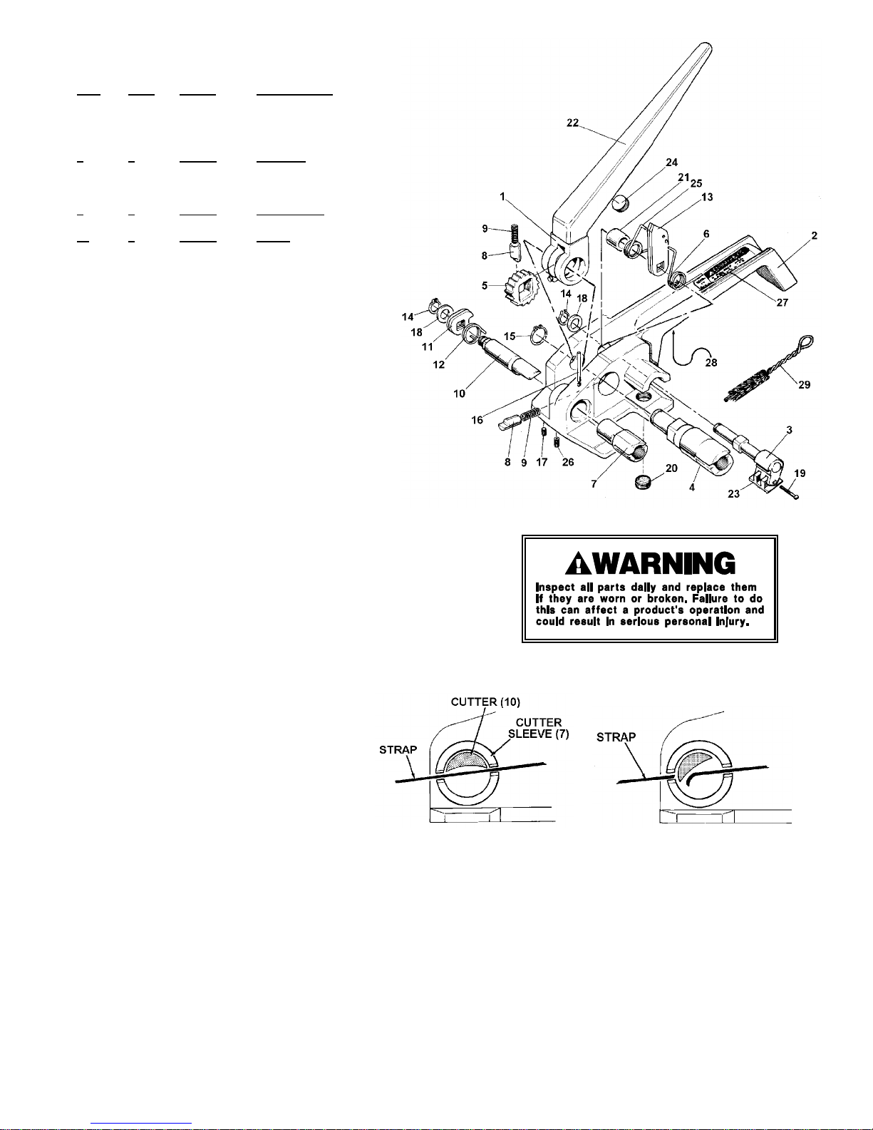
PARTS LIST, WTD-2 (260060)
KEY QTY. PART# DESCRIPTION
1 1 260058 Handle
2 1 424266 Housing base
3 1 260062 Gripper shaft assy.
4 1 260063 Windlass
5 1 260064 Ratchet wheel
6 1 260066 Gripper spring, LH
7 1 424267 Cutter sleeve
8 2 260068 Ratchet stop
9 2 260069 Ratchet spring
10 1 424268 Cutter
11 2 260071 Cutter cam
12 1 260072 Cutter spring
13 2 260073 Gripper cam
14 2 171676 Retaining ring
15 1 074189 Retaining ring
16 1 171678 Roll pin
17 1 260077 Soc. head set screw
18 2 260078 Washer support
19 1 260079 Gripper screw
20 1 260080 Gripper plug
21 1 260081 Spacer
22 1 260082 Plastic sleeve
23 1 260083 Gripper
24 1 260084 Lever stud
25 1 260085 Gripper spring, RH
26 1 260086 Set screw
27 1 260087 Caution sign
28 1 260088 Information sign
29 1 023963 Brush
NOTES:
1. When ordering parts, please show tool model, part number and name.
2. All recommended spare parts are underlined and should be stocked.
3. Standard hardware parts may be obtained from local hardware suppliers.
CUTTER CAM
The cutter (10), must be properly adjusted if the strap
is to be cut from the supply when sealing is
complete. Note the views to right. The cutter rotates
within the cutter sleeve. When properly adjusted, the
cutter is parallel to the slot in the cutter sleeve when
the tension handle is in a rest position. Fully
squeeze the tension handle against the tensioner
frame. The cutter must rotate about 30 degrees and
cover the left hand slot.
Cutter position, with tension handle
is rest position.
Tension handle full closed against
tensioner frame. Cutter rotated about
30 degrees, strap severed.
GRIPPER PLUG
Rotate the gripper plug (20), in or out, as needed, until the teeth of the plug are either flush with the base surface of the tensioner
frame or .005" above the base surface. Once adjusted, stake the plug into position.
MAINTENANCE
Clean and apply a light weight machine oil to all moving parts on a weekly basis. Clean the gripper (23) and gripper plug (20) daily with
a wire brush (29). Debris accumulated in the teeth of either the gripper or the gripper plug must be removed with a small wire brush. A
need to clean the teeth will become apparent when the lower straps slips through the gripper during tensioning.
 Loading...