

Page 1
VT-16/19
TENSION-WELD®
STRAPPING TOOL
Page 2
READ THESE INSTRUCTIONS CAREFULLY.
FAILURE TO FOLLOW THESE INSTRUCTIONS CAN RESULT IN SEVERE PERSONAL INJURY.
GENERAL SAFETY CONSIDERATIONS
1. STRAP BREAKAGE HAZARD.
Improper operation of the tool or sharp corners on the load can result in strap breakage during
tensioning, which could result in the following:
! A sudden loss of balance causing you to fall.
! Both tool and strap flying violently towards your face.
Failure to place the strap properly around the load or an unstable or shifted load could result
in a sudden loss of strap tension during tensioning. This could result in a sudden loss of
balance causing you to fall.
Read the tool's operating instructions. If the load corners are sharp use edge protectors.
Place the strap correctly around a properly positioned load.
! Positioning yourself in-line with the strap, during tensioning and sealing, can result in
severe personal injury from flying strap or tool. When tensioning or sealing, position
yourself to one side of the strap and keep all bystanders away.
! Using strap not recommended for this tensioner can result in strap breakage during
tensioning. Use the correct Signode products for your application.
2. TRAINING.
This tool must not be used by persons not properly trained in its use. Be certain that you
receive proper training from your employer. If you have any questions contact your Signode
Representative.
3. EYE INJURY HAZARD.
Failure to wear safety glasses with side shields can result in severe eye injury or
blindness. Always wear safety glasses with side shields which conform to ANSI
Standard Z87.1 or EN 166.
4. FALL HAZARD.
Maintaining improper footing and/or balance when operating the tool can cause you to fall. Do
not use the tool when you are in an awkward position.
5. CUT HAZARD.
Handling strap or sharp parts could result in cut hands or fingers. Wear protective
gloves.
2
Page 3
6. TOOL CARE.
Take good care of the tool. Inspect and clean it daily, lubricate it weekly and adjust when
necessary. Replace any worn or broken parts.
7. WORK AREA.
Keep work areas uncluttered and well lighted.
Several types of strap can be used with this tool. Use the correct Signode products for your
application. If you need help contact your Signode Representative.
SAFETY PROCEDURES FOR TOOL OPERATION
Before using this tool, read its Operation and Safety instructions.
! Do not exceed the operating air pressures stated elsewhere in the manual.
! Use Signode's approved filter-regulator-lubricator unit (P-008559).
! Never operate a pneumatic tool with a bottled air or gas source.
! For tension adjustments, follow instructions in this manual. For all other adjustments,
repairs or cleaning of the tool, disconnect air supply.
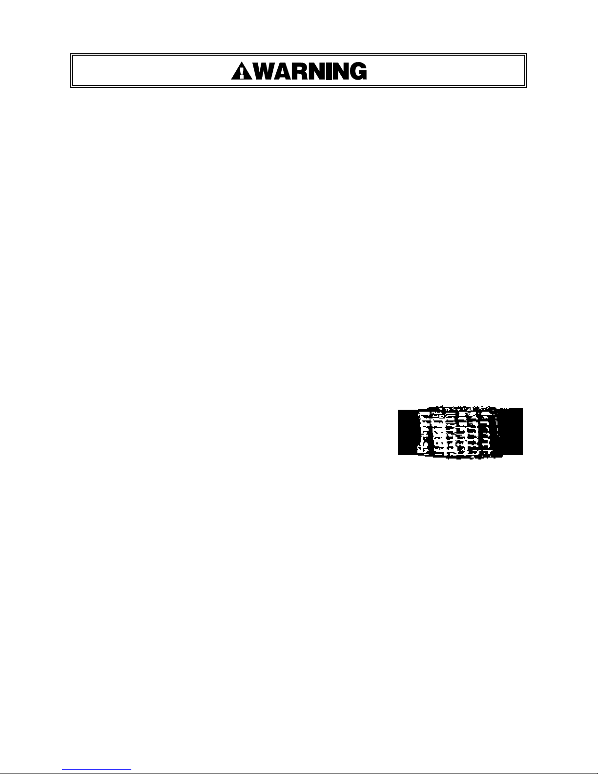
! This tool is a Tension Weld® type sealer. A properly made
joint will appear as shown in the illustration. If the joint does
not appear as shown, then the operator must proceed as
follows:
A. Insure that the tools operating instructions are
being followed before applying another strap.
B. Cut the strap off and apply another.
If the joint still does not appear as shown, then inspect the tool for worn and/or damaged parts.
Replace tool parts as needed. NEVER HANDLE OR SHIP ANY LOAD WITH IMPROPERLY FORMED
JOINTS. Misformed joints may not secure the load and could cause serious injury.
! Tuck strap end back into the dispenser when not in use.
CUTTING TENSIONED STRAP
Use only cutters designed for cutting strap; never use claw hammers, crowbars, chisels, axes or
similar tools. Such tools will cause the strap to fly apart with hazardous force. Before using any
Signode product, read its Operation and Safety Manual.
3
Page 4
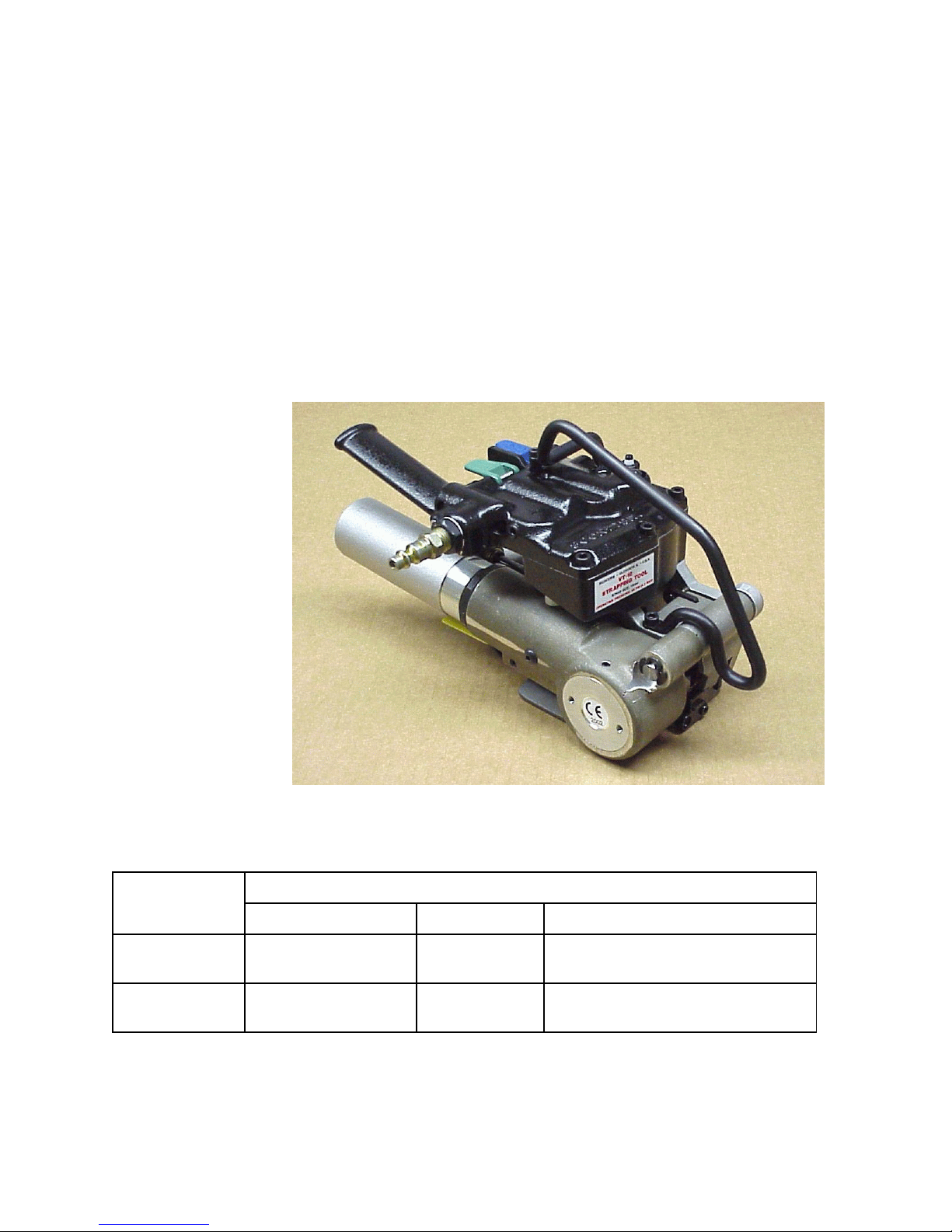
TABLE OF CONTENTS
Page
Page
General Safety Instructions 2
Specifications 4
Major Components 5
Pneumatic Information 6
Strap Size Conversion 11
Operating Instructions 12
Adjustments 16
VT-16 Strapping Tool
Part No. 423990
Parts List, Tool 20
Parts List, Air Motors 24
Troubleshooting 27
Maintenance 31
Overhead Suspension 32
Tool Options 33
VT-19 Strapping Tool
Part No. 423991
SPECIFICATIONS
STRAP
MODEL
VT-16 High Strength
VT-19 High Strength
NOTE: VT-16 tools are factory configured for use with 16mm Tenax Strapping.
VT-19 tools are factory configured for use with 19mm Tenax Strapping.
TYPE WIDTH THICKNESS
16mm Up to 0.055" (1.4mm)
Tenax
19mm Up to 0.055" (1.4mm)
Tenax
4
Page 5
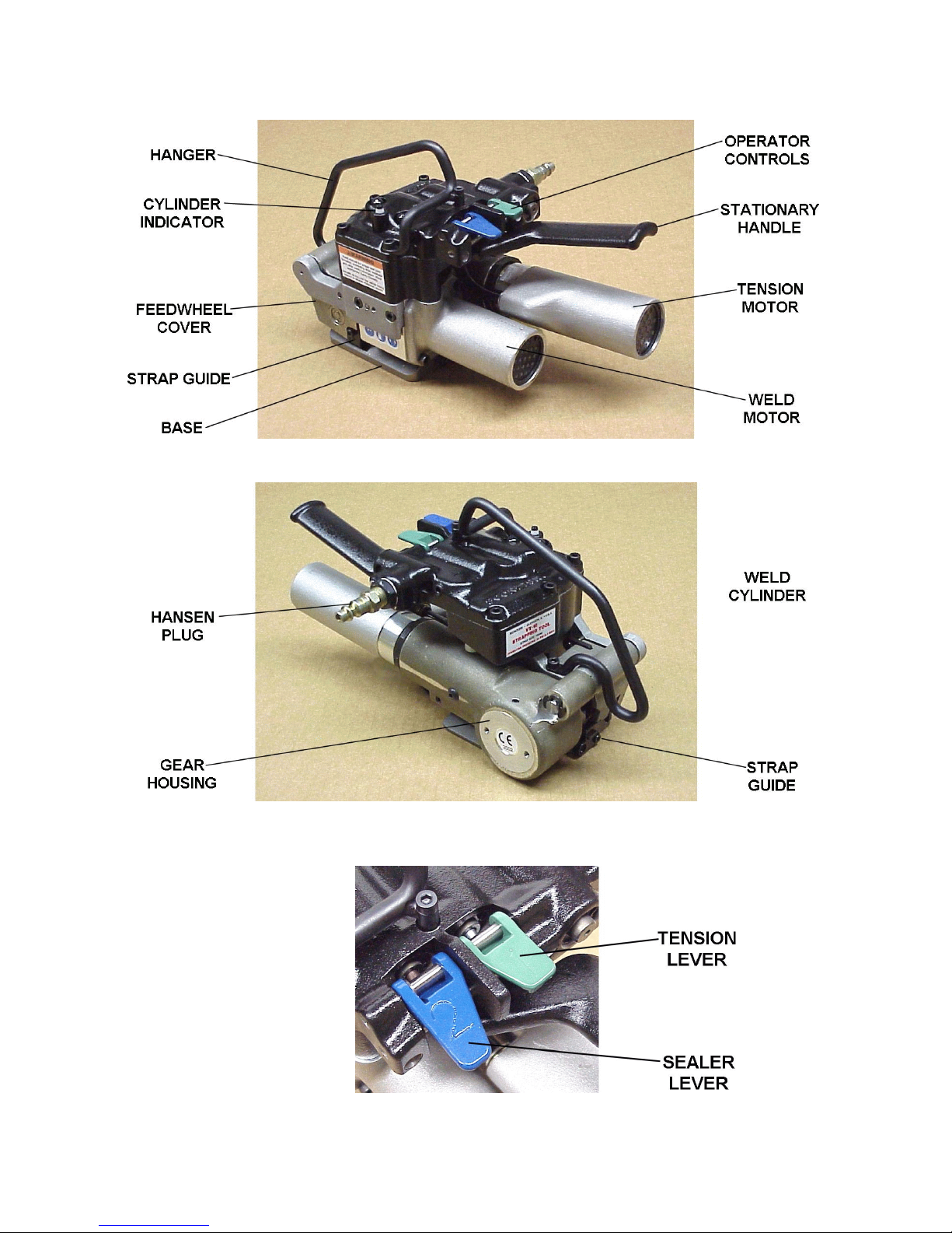
MAJOR COMPONENTS
5
Page 6
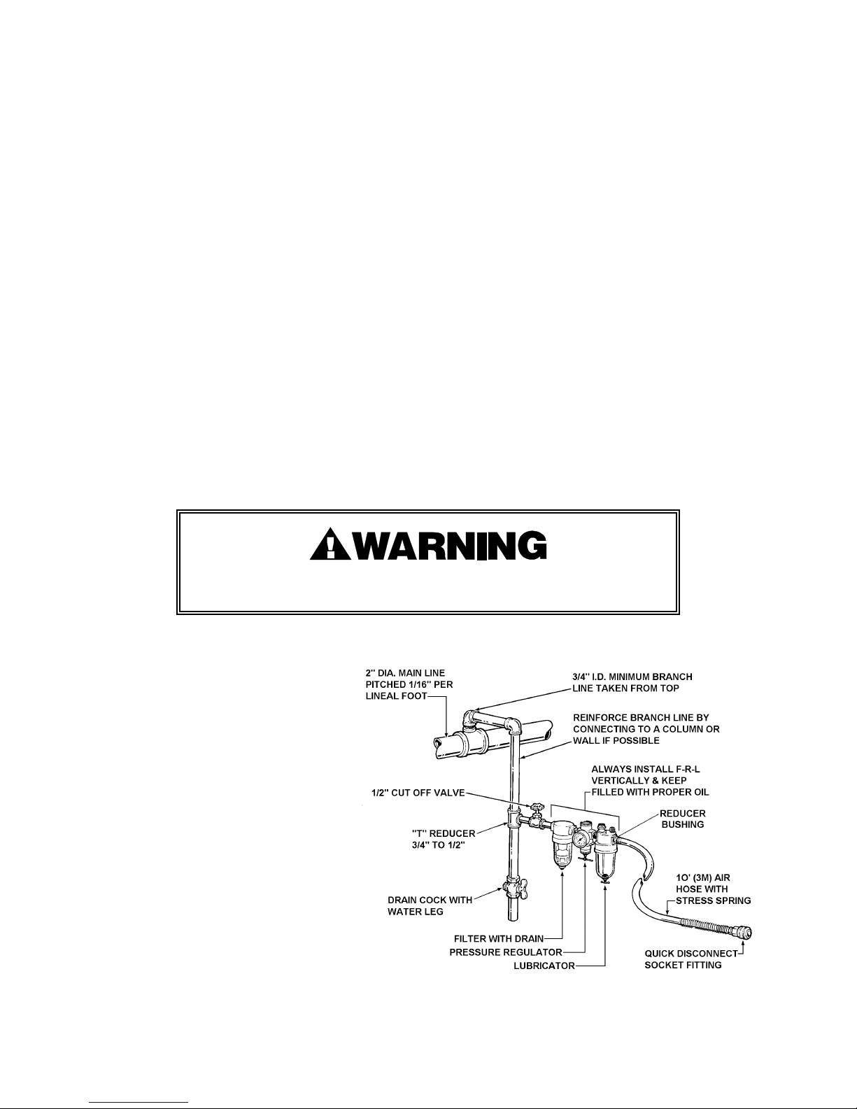
PNEUMATIC INFORMATION
AIR PRESSURE REQUIREMENTS
The VT tools are designed to operate at an air pressure of 90 psig (6.2 Bar).
AIR PRESSURE VS. PERFORMANCE
The air pressure supplied to the VT tool must be a minimum of 85 psig (5.7 Bar) If the air supply
pressure can be adjusted within a range from 85 psi to 90 psi (5.7 - 6.2 Bar) the VT tool's
performance can be fine tuned to a particular application or operation preferences. Changing the
VT air supply pressure to the tool will directly alter the rate at which the tool will take-up the strap
slack and the strap tension. Increasing or decreasing the VT air supply within the suggested 85 to
90 psig (5.7-6.2 Bar) range will not seriously affect the actual welding portion of the strap cycle.
After an initial "Break-In" period, the air motor may become more powerful. If the tool's
performance is effected by this increase in performance, reduce the air motor output by turning
the adjustment screw (Key 98) clockwise as required.
AIR SUPPLY INSTALLATION
If compressor has a good dryer unit, use black pickled pipe. When a dryer unit is not installed,
use galvanized or copper pipe. To perform reliably, a pneumatic tool requires a continuous source
of clean, water-free air at adequate pressure.
Never operate this tool using a bottled air or gas source.
Bottled air/gas sources do not provide consistent operating pressure.
A filter-regulator-lubricator (FRL) unit
must be installed as close to the air
tool as possible, preferably within 10
feet. It should be placed in a
convenient location where it can
easily be drained, adjusted, and filled
with oil. The air hose must have at
least a 1/2" I.D. A quick disconnect
socket fitting is installed on the
stress spring end of the hose for
convenient hookup to the air tool.
Filter-Regulator-Lubricator Unit, 1/2" NPT
(Signode Part No. 424773)
FRL Mounting Bracket
(Signode Part No. 071982)
Air Hose, 1/2" ID, 3/8" Fittings
(Signode Part No. 424774)
Quick Disconnect, 3/8" Fitting
(Signode Part No. 008569)
Reducer Bushing, 1/2" to 3/8"
(Signode Part No. 426767)
6
Page 7

Filter and lubricator bowls are made of polycarbonate material. Do not install where bowls may be
exposed to materials incompatible with polycarbonate. Certain oils, solvents, and chemicals or
their fumes can weaken these bowls and possibly cause them to burst. Clean only with warm
water. A cut-off valve placed ahead of the filter will be useful when cleaning the filter or
replenishing the lubricator.
MOISTURE
Moisture is always present in air lines due to condensation within the lines as the air cools. Steps
must be taken to remove this moisture and to keep it from the air tool. This is because water
tends to wash away lubricants and cause corrosion, sticking and failure of internal parts.
The main line should be pitched so the far end terminates in a water leg. Branch lines are taken
from the top of the main, never off the bottom. Every branch should have a water leg at its lowest
point, with a drain cock which is drained daily.
If these precautions are taken and water is still present, an after cooler and a moisture separator
are required between the compressor and the air receiver tank. A large air line separator can be
installed in the air tool line, but precautions must be taken to insure that it will be drained daily,
before the air tool is operated.
Water in air lines is a constant threat to the proper operation of air tool. Even near freezing
operating conditions, a good refrigerant type dryer is essential. A good dryer will remove 95% or
more of water right at the compressor. The remaining moisture is removed at the water leg in the
piping system or in the filter (Part No. 008559).
NOTE: Additional information is available in the Signode publication, "Air Supply Manual" (Part
No. 186038). If you have any questions, contact your local Signode Representative.
LUBRICATION
The air motor must be properly lubricated. This is achieved by keeping the air line lubricator filled
with oil and correctly adjusted. Without proper lubrication, the motor will become sticky and the
tool will give low and erratic tension and be difficult to release from the strap.
Install the lubricator as close to the air tool as possible. The arrow on the lubricator's top surface
must point in the direction of air flow. For proper operation, oil must drop through the lubricator
sight glass at a rate of 1 to 4 drops per minute. This rate is checked while the air tool is running
free. Only 20% of this oil is actually delivered to the tool. The remaining oil drops back into the oil
reservoir. The unit is factory set and should require no adjustment. If an adjustment is required,
the adjusting screw on top of the lubricator may be turned as marked to reduce or increase the
flow of oil.
The correct grade of oil must be used in the lubricator; too heavy an oil will not provide sufficient
lubrication and will cause sticking and sluggish operation of the air tool. Recommended oils are
any good grade of rust and oxidation inhibiting oil with a viscosity of 80-120 S.U.S. at 100 degrees
Fahrenheit. (0.15 to 0.25 cm2 /sec. at 38 degrees Celsius), such as:
Non Fluid Oil Co., grade #LS-1236 Signode oil - Part No. 008556
NOTE: Some oils contain anti-wear additives which may disable the air motor. Be certain to use
recommended oil.
7
Page 8
PNEUMATIC INFORMATION, Continued
Several drops of lubricator oil added to the inlet of the air motor or into the air line each day will
help insure good operation. A noticeable reduction of air motor performance can usually be
corrected by squirting a few drops of oil into the air line.
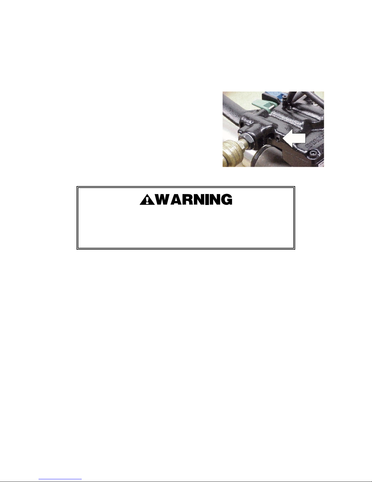
STRAP TENSION
Strap tension is controlled by turning the adjustment screw
(Key 98) as shown by arrow, in 1/4 increment turns counterclockwise to increase strap tension and clockwise to reduce
strap tension.
NOTE: Operating air pressure must be set between 85 and 90
psi (5.7-6.2 Bar). With accurately controlled air pressure the
tension will be uniform on all straps, provided the operator
allows the air motor to stall.
Strap breakage hazard.
Strap can break if inlet air pressure to tool exceeds 90 psig (6.2 bar).
Strap breakage can result in severe personal injury.
Maximum operating air pressure is 90 psig (6.2 bar).
AIR CONSUMPTION
Air consumption in cubic feet per minute (cfm) for the VT can be calculated as follows: cfm = (a) x
(b) x (0.40)
a = Number of straps applied per minute.
b = Number of seconds motor is on per strap during tensioning, from start to deceleration
to stall including stall time while making joint.
0.40 = VT efficiency ratio.
Example Calculation: Peak strapping load is 4 straps/min. so a = 4
Air motor is on 5 seconds/strap, so b = 5
VT efficiency ratio is 0.40
(a)x(b)x(0.40) 6 4x5x0.40=8 cubic ft/min.
4x5x0.67=13.4 cubic meters/hr. (13.4M3/hr.)
Air pressure is assumed to be 90 psig (6.2 Bar) with recommended size and length of air hose.
Volume of air is at room temperature and sea level pressure, or so-called "free air" conditions. For
more detailed information about air supply systems refer to Signode manual Part No. 186038.
8
Page 9

COLD WEATHER OPERATION
Signode pneumatic powered tools operate reliably in a wide range of operating temperatures.
However, operating conditions below an ambient temperate of 41°F (5°C) may require the
compressed air to be dried. Dried air typically avoids any moisture and freezing tool issues.
Air motors typically use air compressed from 70 psi to 90 psi (4.8 to 6.2 Bar) and exhaust the
compressed air approximately at 15 psi (1 Bar). The highly compressed air cycled through the
tool, then exhausted to atmospheric pressure, may result in the discharged air freezing. Freezing
air will contribute to reduced motor and tool performance.
Freezing air (icing) is a problem to all compressed air driven motors. Factors which can
contribute to icing are:
• Compressed air vs. ambient air temperatures.
• Compressed air vs. ambient air dew points.
• Compressed air pressure.
• Flow rate of the compressed air exhausted through tool.
• Contaminated air quality.
• Cycle rate of tool.
If a tool does not operate satisfactorily in freezing temperatures, certain steps can correct the
problem. The following steps can be taken to improve cold weather operation of the tool:
a. Use of an air line dryer adjacent to the compressor.
b. Use lubricant recommended by Signode. Signode has tested the use of anti-freezes, none
work well in air tool; the tool will gum up when anti-freezes are introduced and will not
function properly.
c. If possible, run the air supply line to a indoor located Filter-Regulator-Lubricator or relocate
the F-R-L to a warmer operating area.
d. Eliminate any air line restrictions (review “Air Supply Installation” in this manual).
9
Page 10
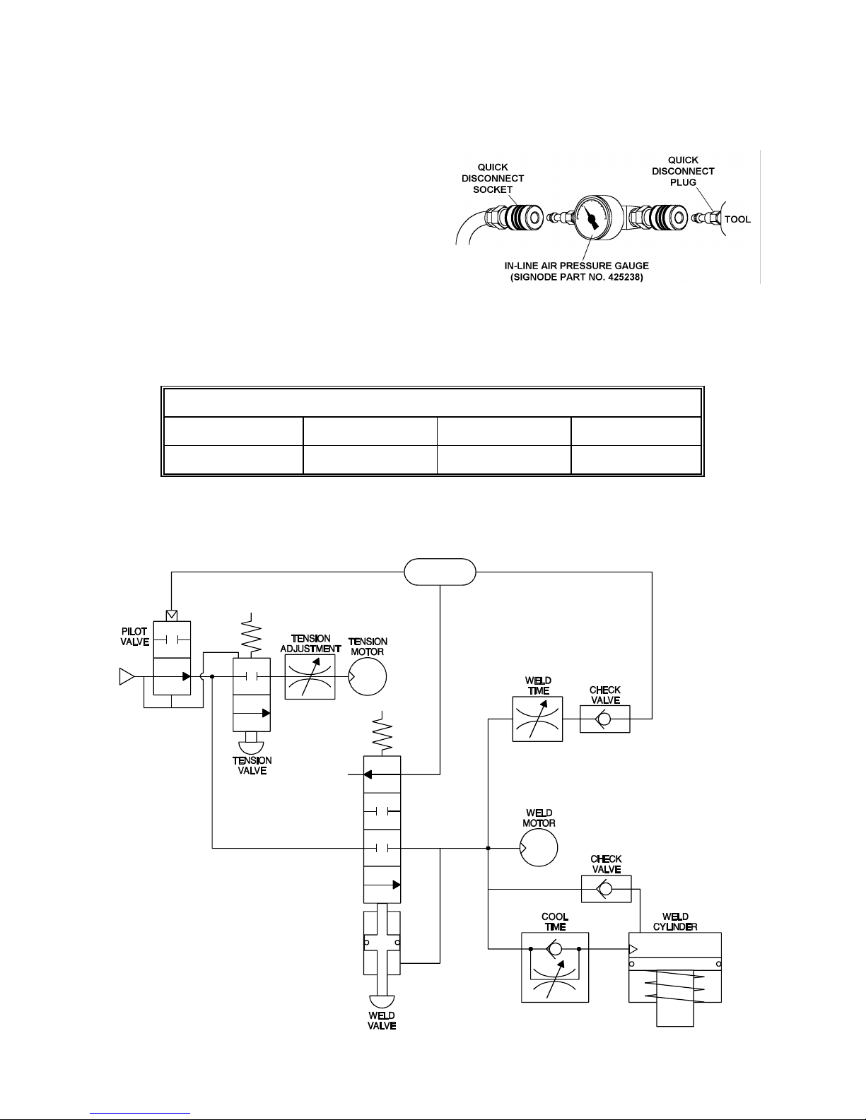
PNEUMATIC INFORMATION, Continued
AIR PRESSURE DROP
Confirm air pressure calibration by comparing it to a
master gauge placed in-line where the quick
disconnect fitting attaches to the tool.
Air pressure at the tool can then be monitored as
the tool cycles. Use the following information
shown on the chart below for comparing the various
minimum air pressures while the VT tool cycles.
If pressure readings fall below the minimums, inspect your air supply system as well as the tool
for worn and/or broken parts. Contact your Signode representative if you have any questions.
AIR LINE PRESSURE MINIMUMS FOR CYCLING TOOL
IN-LINE GAUGE READING PSI (BAR)
SUPPLY/STATIC TAKE-UP STALL WELDING
90 (6.2) 61 (4.1) 80 (5.4) 75 (5.2)
PNEUMATIC CIRCUIT DIAGRAM
10
Page 11
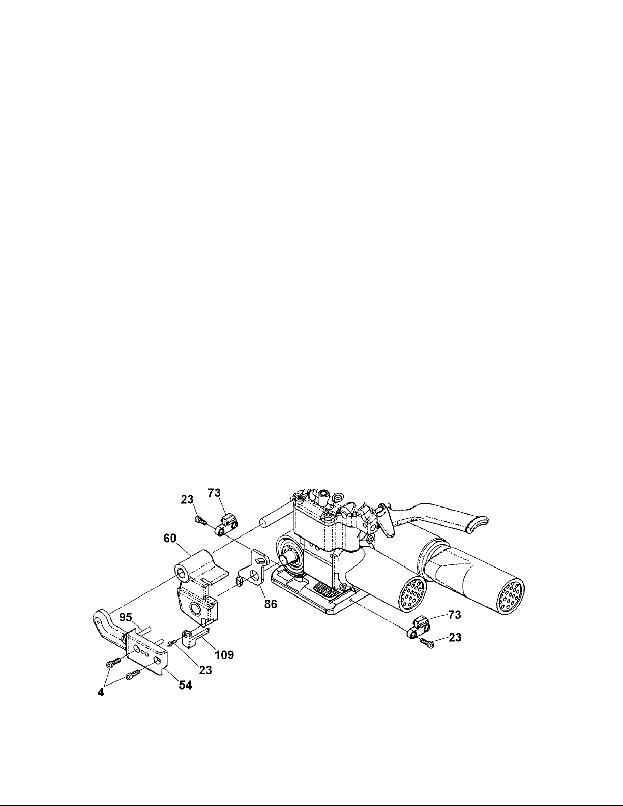
VT STRAP SIZE CONVERSION
NOTE: All parts named below to convert a VT tool can be found in the original shipping box.
Use th following instructions to convert (or reconfigure) a tool from 16mm strap to 19mm or vice
versa.
1. The two inner guides (Key 73) must be reversed. Remove the mounting screw (Key 23) and
reposition the guide so that the strap contact surface marked “16" or “19" is facing the strap
path. Use Loctite #242 (or equivalent) when reinstalling the mounting screws.
2. The outer guide (Key 109) must be exchanged with the appropriate guide for the strap size
(Signode P/N 423956 for 16mm and P/N 423957 for 19mm). Guides can be identified by the
outer surface being marked “16" or “19". Remove the guide’s mounting screw (Key 23) and
install the proper guide. Use Loctite #242 (or equivalent) when reinstalling the mounting
screw.
3. The guide plate (Key 86) must be exchanged with the appropriate guide plate for the strap size
(Signode P/N 423978 for 16mm and P/N 423979 for 19mm). Guide plates can be identified by
the outer surface being marked “16" or “19". Replace the guide plate by first removing support
bar (Key 54) which is secured by two mounting screws (Key 4).
NOTE: The support bar fits tightly into the tool. Exercise care when removing so as not to
cause any binding from end to end as it is removed.
Continue to remove the outer link (Key 60) and the existing guide plate (Key 86) at the same
time.
4. Install the appropriate guide plate and outer link together as the parts are positioned on the
tool. Reinstall the support bar making sure that the alignment pin (Key 95) installs into the slot
of the new guide plate.
5. If desired, the tool nameplate may also now be exchanged to display the appropriate strap size
(Signode P/N 423987 for VT-16 and P/N 423988 for VT-19).
11
Page 12
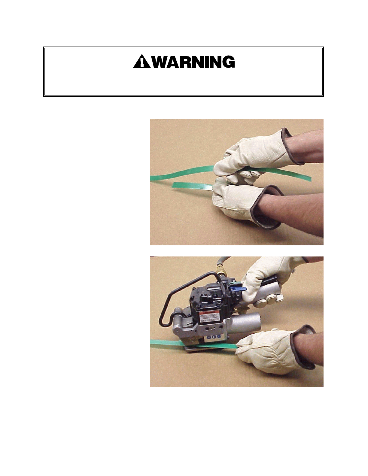
OPERATING INSTRUCTIONS
Wear safety glasses. Stand to one side of the strap when tensioning.
Make sure all bystanders are clear before proceeding.
PLEASE NOTE: Do not operate tool without strap, as damage to the tool may occur.
1. With the dispenser placed
behind you, bring the strap over
the top and around the package,
place the straps together and
remove any excess slack.
2. Using your right hand, squeeze
the tension motor and stationary
handle together to open the
feedwheel and strap path. Using
your left hand, insert the
overlapped straps under the
feedwheel and through the
welding mechanism.
Leave only a short tail ahead of
the feedwheel and make sure
straps are aligned behind the
tool. Do not make a joint over a
void area of the package.
12
Page 13
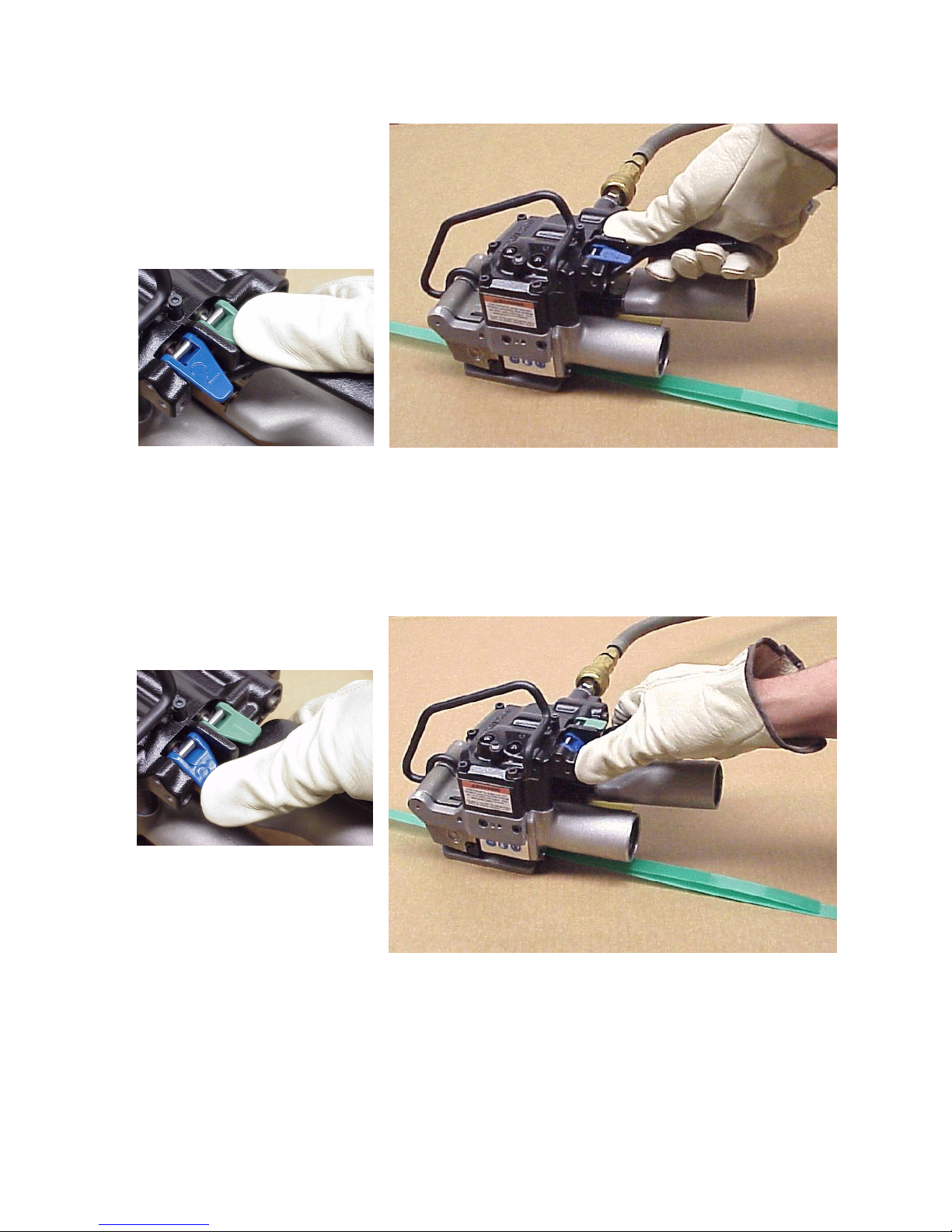
3. Recheck the strap alignment at
the rear of the tool and realign if
necessary. Release the tension
motor.
Press down the Green Tension
Control Lever to begin
tensioning the strap.
When the tension motor stalls, indicating completion of tension, release the control lever. The
strap will remain tensioned around the package.
NOTE: If the strap alignment is unsatisfactory or the tool needs to be removed before sealing.
Remove the tool as described in Step 5 of these instructions.
4. Press the Blue Sealer Control
lever to begin the sealing cycle.
It is not necessary to continue
holding the lever down once
the weld cycle has started.
13
Page 14
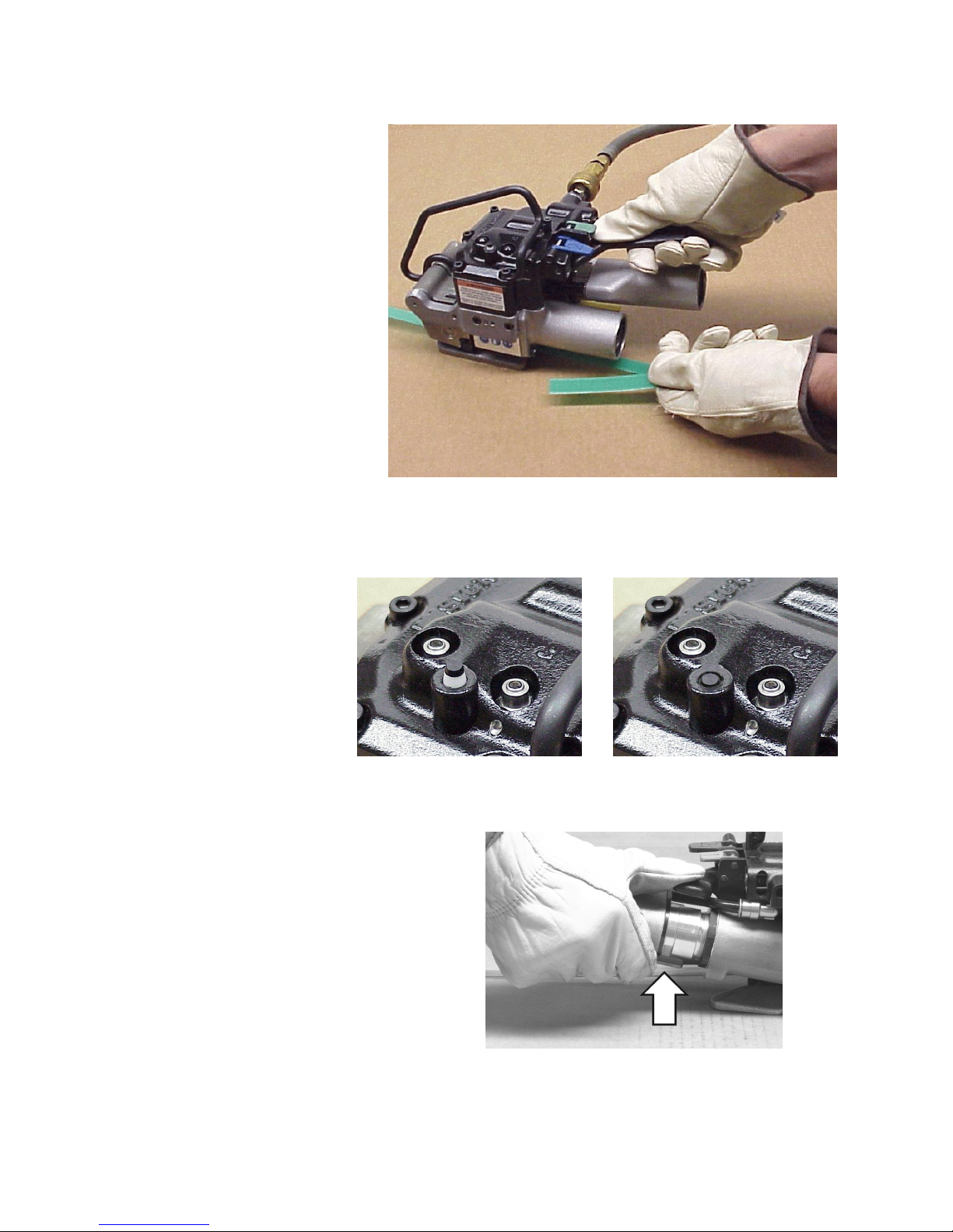
OPERATING INSTRUCTIONS, Continued
5. The internal weld timer is
energized. The main piston
brings the welding pads
together and the strap is
welded.
The supply end of the strap is
then cut off. Pull the cut strap
away from the tool during
welding. The tool will continue
through the weld cycle and stop
automatically.
5. When the weld cycle has completed the weld mechanism slowly returns to the neutral
position. This allows the newly welded strap joint to cool down properly. The tool can be
easily removed once the weld mechanism has completely returned to the neutral position.
NOTE: The weld
mechanism’s return to the
neutral position can be
identified by the indicator
located on the top of the
tool. When the indicator is
in the down position the
weld mechanism is still
engaging the strap. When
the indicator is in the up
position the weld
mechanism has returned to
the neutral position. The
INDICATOR IN THE UP POSITION
(NEUTRAL)
tool can then be easily
removed from the strap.
Remove the tool from the strap by first lifting
up the tension release lever found on the
bottom of the gear housing while squeezing
the tension motor and stationary handle
together to open the strap path.
INDICATOR IN THE DOWN POSITION
(ENGAGED)
NOTE: Failure to wait for the weld mechanism to return to the neutral position may lead to an
improperly formed joint which may lead to joint separation and make tool removal difficult.
14
Page 15
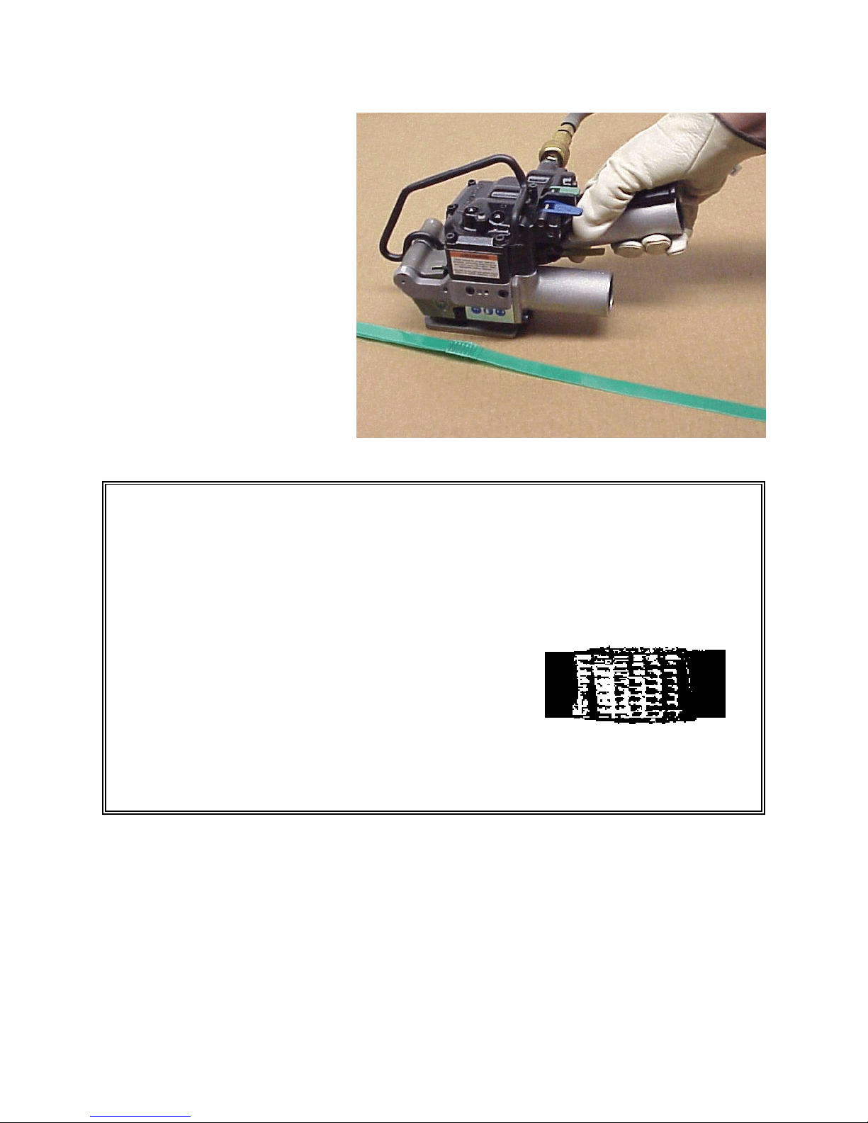
6. Swing the tool out from the
completed strap joint. Inspect
the joint to make sure the straps
have been properly welded.
STRAP JOINT INSPECTION
This tool is a Tension Weld® type sealer. A properly made joint will appear as shown in the
illustration. If the joint does not appear as shown, then the operator must proceed as
follows:
1. Insure that the tool operating instructions are being followed before applying another
strap.
2. Cut the strap off and apply another.
A good weld will show some material displacement along
the edges. The welded area should extend the full length
and width of the gripper impression.
If the joint still does not appear as shown, then inspect the tool for worn and/or damaged
parts. Replace tool parts as needed. NEVER HANDLE OR SHIP ANY LOAD WITH
IMPROPERLY FORMED JOINTS. Misformed joints may not secure the load and could cause
serious injury.
15
Page 16
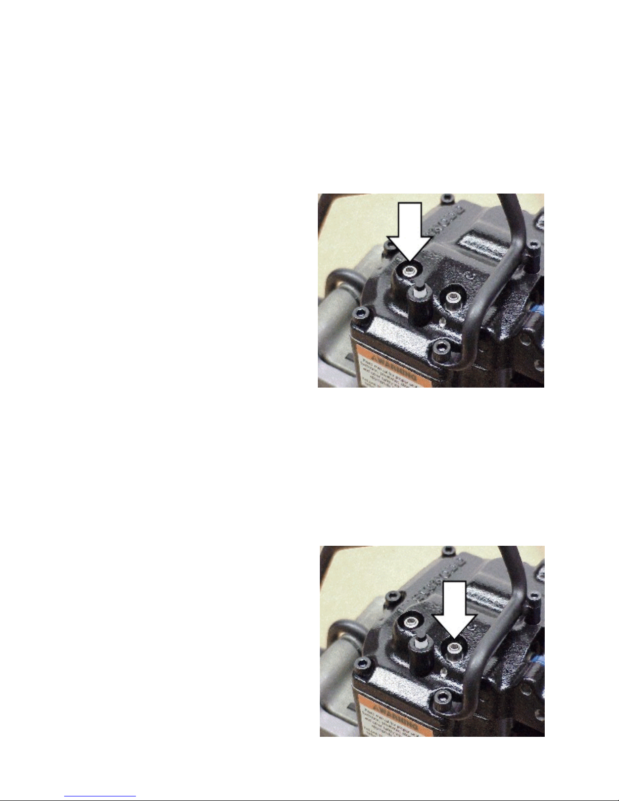
TOOL ADJUSTMENTS
WELDING TIME
Weld time has been factory adjusted to provide acceptable weld strength when using High
Strength Tenax (polyester) type strap. Weld time may need to be adjusted due to air supply
differences, tool wear, etc. Adjustments are made by turning the adjustment screw, located on the
cover plate, using a small screwdriver. Turn the screw clockwise to increase weld time and
counterclockwise to decrease weld time.
Establishing the correct weld time is a matter of trial and error and should be conducted as
follows.
1. Remove the cap which protects the
adjustment screw. Adjust the screw in 1/8 to
1/4 turn increments only.
2. Apply a strap and make a weld.
3. Compare the weld made with the illustrations
shown on page 13 of this manual. A good
weld will displace some material along the
outer edges of the joint.
4. If you are unable to produce an acceptable
joint or if you have any questions as to
whether your tool is producing good weld
strength, contact your Signode Sales
Representative.
5. Replace the cap over the screw.
LOCATION OF WELD TIME ADJUSTMENT
WELD COOLING TIME
Cool time has been factory adjusted to allow the proper time for a weld to properly cool. The cool
time adjust controls how fast or slow the main piston bleeds off air pressure allowing the weld
pads to separate from one another.
Cool time may also need to be adjusted due to air supply differences, tool wear, etc. Adjustments
are made similar to weld time. Turning the screw clockwise increases cool time and
counterclockwise to decrease cooling time.
Establishing the correct cool time is a matter of trial and error and should be conducted as
follows.
1. Remove the cap which protects the
adjustment screw. Adjust the screw in 1/8 to
1/4 turn increments only.
2. Apply a strap and make a weld.
3. A properly adjusted cool time should allow the
strap joint to cool for approximately two to
three seconds.
NOTE: Cool time which is too short may lead
to strap joint separation.
4. Replace the cap over the screw.
LOCATION OF COOL TIME ADJUSTMENT
16
Page 17
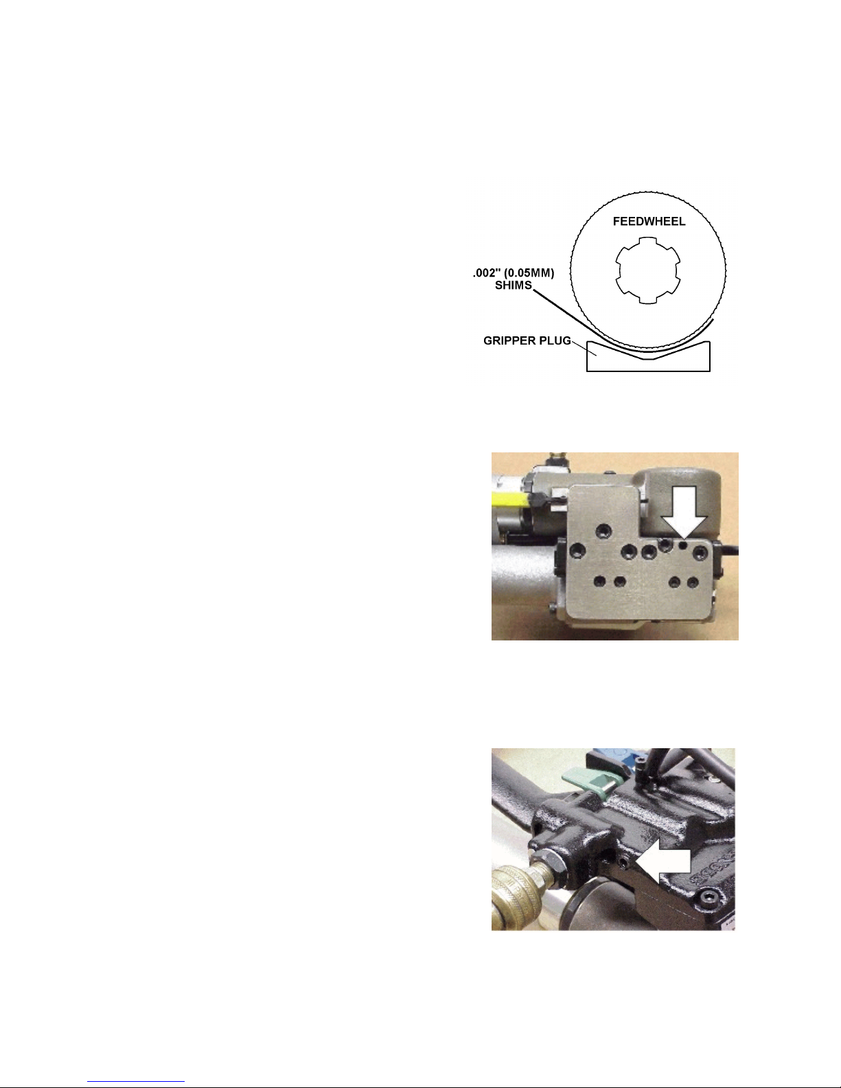
FEEDWHEEL TO GRIPPER PLUG
The feedwheel to gripper plug clearance may require readjustment if the feedwheel or gripper plug
has been replaced. The feedwheel clearance should also be inspected during routine tool
maintenance procedures. Adjust the feedwheel clearance as follows:
1. Squeeze the tension motor and stationary handle
together to open the feedwheel gap. Place multiple
(4 to 8) layers of .002", 1/2" wide (.05 x 12mm) shim
stock between the feedwheel and the gripper plug.
NOTE: Do not use a single shim such as .008"
(.20mm) as thicker shims may not conform to the
feedwheel shape, resulting in inaccurate clearance
measurements.
2. Release the tensioner motor to pinch the shims
between the feedwheel and the gripper plug.
Holding the shims with one hand, jog the tension
motor on and off to rotate the feedwheel at least one
full revolution. If properly adjusted the tool should
lightly tug at the shims while rotating. Clearance between the feedwheel and gripper plug at
this point should fall between .008" to .016 (.20mm to .40mm).
3. If the feedwheel needs to be adjusted, use a 3mm hex
wrench to turn the adjustment screw which can be
accessed through the bottom of the tool base.
Turn the adjustment screw clockwise for greater
clearance and counter-clockwise for less clearance.
Turn the adjustment screw only in 1/8 turn increments.
After each 1/8 turn, repeat the adjustment testing as
described in step 2.
4. Once the proper clearance has been found the tool
can be returned to service.
NOTE: Never turn out the adjustment screw more than
1/8 turn at a time without testing or completely remove
the adjustment screw. These actions will severely
damage both the feedwheel and gripper plug.
STRAP TENSION
Strap tension is controlled by turning the adjustment
screw (Key 98) as shown by arrow, in 1/4 increment turns
counter-clockwise to increase strap tension and clockwise
to reduce strap tension. Use the 4mm hexwrench (Signode
Part No. 274467) included with every new tool.
NOTE: Operating air pressure must be set between 85 and
90 psi (5.7-6.2 Bar). With accurately controlled air pressure
the tension will be uniform on all straps, provided the
operator allows the air motor to stall.
FEEDWHEEL ADJUSTMENT
SCREW LOCATION (ARROW)
17
Page 18
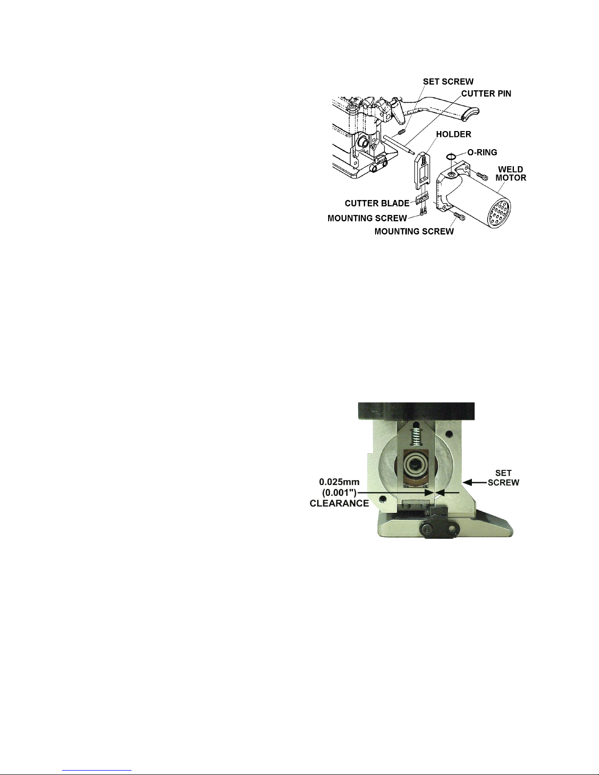
TOOL ADJUSTMENTS, Continued
STRAP CUTTER
The VT strap cutter has two serrated cutting edges.
After the first edge has become dull or strap cut-off
becomes difficult the blade can be remounted to use
the second cutting edge. Once both edges have
become worn the blade should be replaced. Use the
instructions below to remount, install and adjust a
new cutter blade.
1. Remove the two mounting screws which secure
the air motor to the tool body. Remove the weld
motor from the tool by turning the motor counterclockwise to release the O-ring which seats on
the top of the motor.
NOTE: The small spring contained in the holder does not need to be removed to change
the cutter blade.
2. The cutter blade group of parts can now be removed from the tool. Continue to also remove
the cutter pin from the tool.
3. Remove the two smaller screws which mount the cutter blade to the holder. Rotate the cutter
blade to the new cutting edge and reinstall the mounting screws.
NOTE: If both cutting edges are worn replace the cutter blade at this point.
4. Reinstall the cutter group of parts back into the tool. Before installing the cutter pin inspect
the cutter holder movement within the tool.
A. The holder should move freely up and
down in the tool body. If the holder does
not move freely inspect the tool for debris
or damage.
NOTE: If the holder has been replaced
it may be necessary to adjust the set
screw which controls the side clearance.
B. The holder should not be able to move
from side to side. Excessive side to side
clearance will result in poor strap cut-off. If
the holder does move side to side, tighten
the set screw until it just touches the side
of the holder, approximately a 0.025mm
(0.001") clearance.
5. Once the cutter holder has been inspected and adjusted, continue to reinstall the remaining
parts in the order that they were removed.
6. Run a few test cycles on the tool to confirm that the strap cut-off performs properly.
18
Page 19

BLANK
19
Page 20

PARTS LIST
KEY QTY PART NO DESCRIPTION
1 1 008552 OIL SEAL
2 1 008734 BEARING FAFNIR B-542
3 6 010035 SHCS M6 X 18 LG
4 13 170304 SHCS M5 X 16 LG
5 1 014527 BEARING FAFNIR 7202W
6 1 020704 HANSEN PLUG
7 1 020728 O-RING SAE # 007
8 8 022789 O-RING SAE # 016
9 1 023096 O-RING SAE # 131
10 1 023097 BEARING FAFNIR 9101K
11 5 023446 O-RING SAE # 012
12 1 024631 FILTER ASSEMBLY
13 1 069177 O-RING SAE # 038
14 1 091354 O-RING SAE # 330
15 2 091624 O-RING SAE # 010
16 2 092747 O-RING SAE # 018
17 1 092772 O-RING SAE # 014
18 1 094295 O-RING SAE # 008
19 3 177721 SHSS M6 X 16 LG W / LG LCK
20 2 181261 DOWEL PIN 5 X 10 LG
21 2 259935 SHCS M3 X 12 LG
23 3 276191 SHCS M4 X 10 LG
24 1 278994 SHCS M4 X 45 LG
25 1 NA CE LABEL
26 1 286373 3 ICON SAFETY LABEL
27 2 292467 BHCS M5 X 8
28 4 424555 BEARING GARLOCK MB 1012 DU
29 1 306335 RETAINING RING TRUARC N5000-37
30 1 423493 DOWEL PIN 5 X 16 LG
31 1 423582 CAMOZZI CARTRIDGE 6700-5
32 2 423889 BEARING GENERAL 6001-2RS
33 1 426887 TENSION MOTOR (20.25 : 1)
34 1 426151 BEARING SLEEVE
35 1 423894 SPIROID PINION
36 1 423895 FEEDWHEEL SHAFT
37 1 423896 BEARING CAP
38 1 426894 GEAR HOUSING
39 1 426886 O-RING SAE # 027
46 1 423908 SPRING LEE # LC-018B-7
47 1 423909 FEEDWHEEL
48 1 423910 TENSION GRIPPER (MACH)
49 1 426885 O-RING SAE # 015
50 1 423912 LOWER WELD GRIPPER (MACH)
51 1 423915 FRAME (MACH)
52 1 423916 BASE, MACHINED (STANDARD)
1 424763 BASE, MACHINED (OPTIONAL)
53 1 424560 CUTTER HOLDER
54 1 423920 SUPPORT BAR
55 1 423921 HANDLE
56 1 423922 CUTTER PIN
57 1 423923 PISTON
58 1 423924 SPRING (O & G)
59 1 423925 VIBRATOR ARM
60 1 423927 OUTER LINK
61 1 423932 SPRING LEE # LC-036G-1
62 1 423933 UPPER WELD GRIPPER
63 1 423934 ECCENTRIC SHAFT
20
Page 21
KEY QTY PART NO DESCRIPTION
64 1 427067 CYLINDER HOUSING
65 1 423937 PIVOT PIN
66 1 423938 SPACER
67 1 423940 BEARING TORRINGTON # M881
68 3 423942 RETAINING RING KLIPRING # 5304-43
69 1 423943 SPRING # LC-040C-6
70 1 423944 SPRING # LC-038D-17 ! When ordering parts please indicate
71 1 423945 SPRING # LC-042D-17 tool model, part number and description.
72 1 423947 SEAL VALVE STEM
73 2 423950 INNER GUIDE 16 / 19 ! Recommended spare parts are
74 1 423958 SUPPORT SHAFT underlined and should be stocked.
75 1 423960 TENSION LEVER
76 1 423961 SEAL LEVER ! Common hardware parts can be
77 1 423962 PISTON obtained at any local hardware supply.
78 1 424567 TENSION VALVE STEM
79 1 423964 SEAL VALVE SLEEVE
80 2 423965 LEVER PIN
81 1 423966 TUBE
82 1 423967 DOWEL PIN 8 X 32 LG
84 2 423969 SHSS M5 X 10 LG CUP POINT
85 4 423970 SHCS M4 X 5 LG
86 1 423978 GUIDE PLATE (VT-16)
1 423979 GUIDE PLATE (VT-19)
87 1 423980 WELD MOTOR ASSEMBLY
88 2 423981 FLOW CONTROL CAMOZZI SCU-602-M5
89 1 423982 PILOT VALVE COVER
90 1 423987 NAMEPLATE (VT-16)
1 423988 NAMEPLATE (VT-19)
91 1 423994 BEARING INA NK 16/16
92 1 423995 O-RING SAE # 124
93 2 086190 RETAINING RING KLIPRING # 5304-37
94 2 423997 BEARING INA HK0808
95 1 423999 DOWEL PIN 5 X 22 LG
96 3 424375 RETAINING RING 19 X 1.0 DIN 472
97 1 424376 CHECK VALVE ASSEMBLY
98 1 424380 ADJUSTMENT SCREW
99 1 424381 SPIROID GEAR 9.25:1
100 1 424566 TENSION VALVE SLEEVE
101 1 424383 HANGER ASSEM. HORIZ/VERT
102 2 424392 RETAINING RING CIRCLIP 4 X 0.7
103 1 424490 INDICATOR
104 1 424492 COVER ASSEMBLY
105 1 424493 SPRING # LC-040E-13
106 1 424550 PILOT VALVE ASSEMBLY ___
107 2 424552 CAP
108 1 423953 WARNING LABEL
109 1 423956 OUTER GUIDE (VT-16)
1 423957 OUTER GUIDE (VT-19)
110 1 424557 CUTTER INSERT
112 1 036414 1/4, 90° STREET ELBOW
113 2 004164 O-RING, SAE #011
114 2 010031 SHCS, M5 x 25 LG
117 1 424762 O-RING, SAE #106
123 1 425225 MOTOR GUARD (OPTIONAL)
Only use valve cartridge (Key 106),
Signode Part No. 424550. Cartridges can
be identified by the OEM code “D2073"
marked on the back surface of the part.
21
Page 22
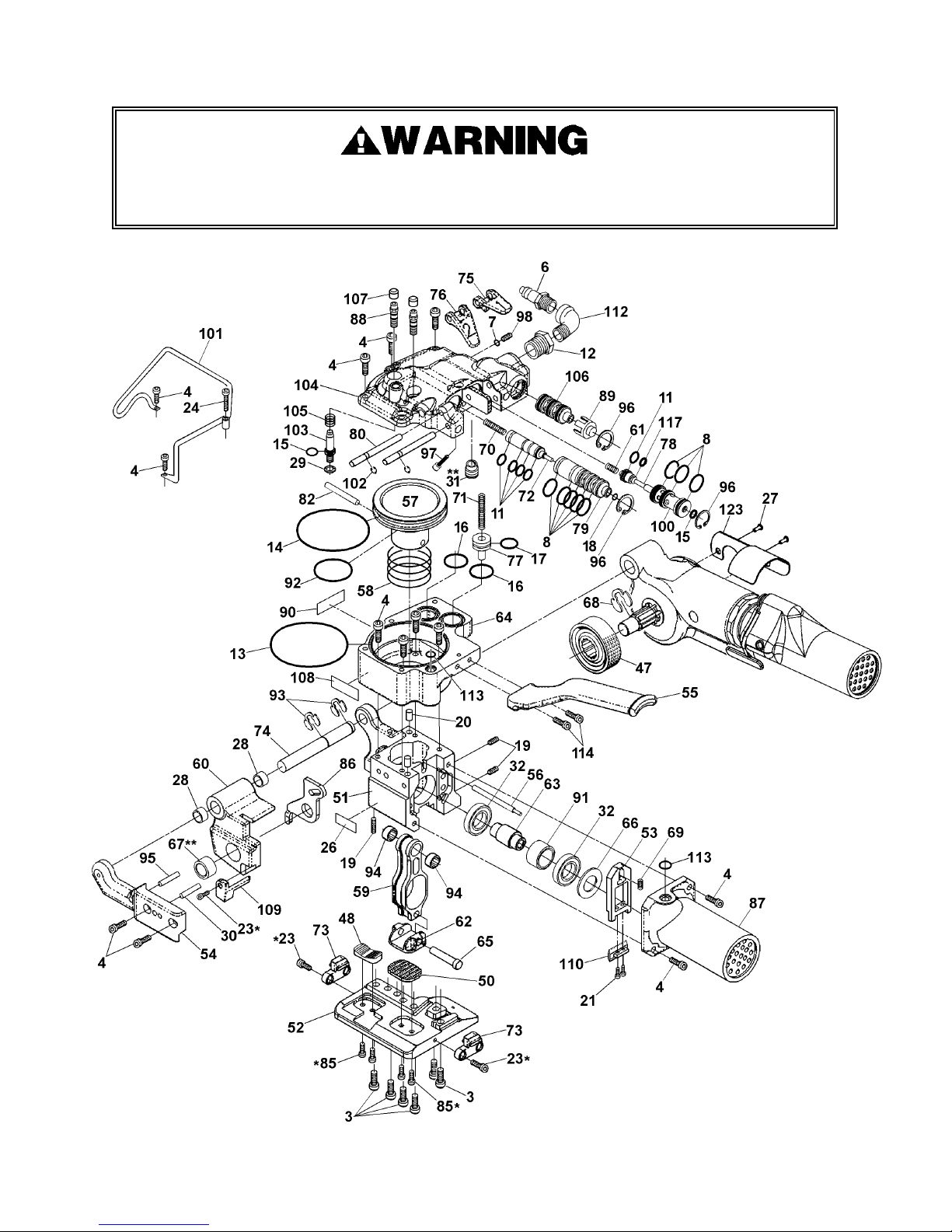
NEVER remove the air valves (Key 79, 100 & 106) when air is connected to the tool. Removing
an valve with air to the tool will cause the valve to violently release from the tool.
22
Page 23
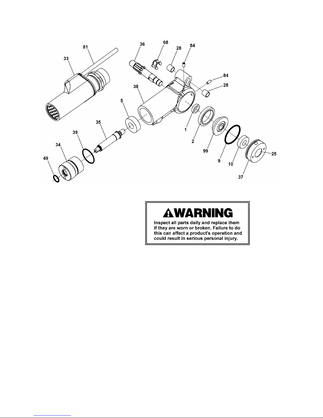
* Use Loctite #242 or equivalent.
** Use Loctite #609 or equivalent.
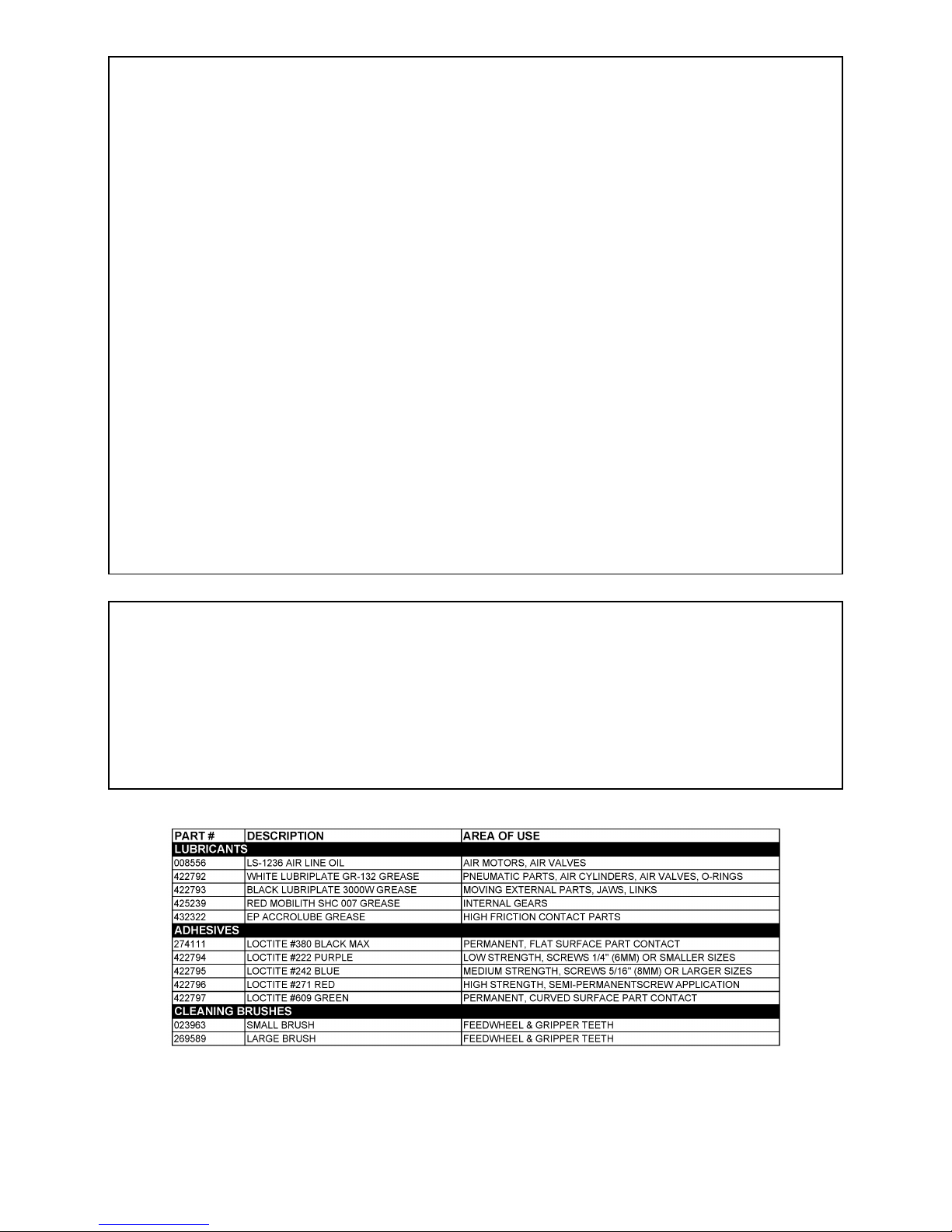
NOTE: For optimum tool performance, fill gear housing (Key 38) one-third full of Red Mobilith SHC
007 Grease (Signode Part No. 425239).
23
Page 24
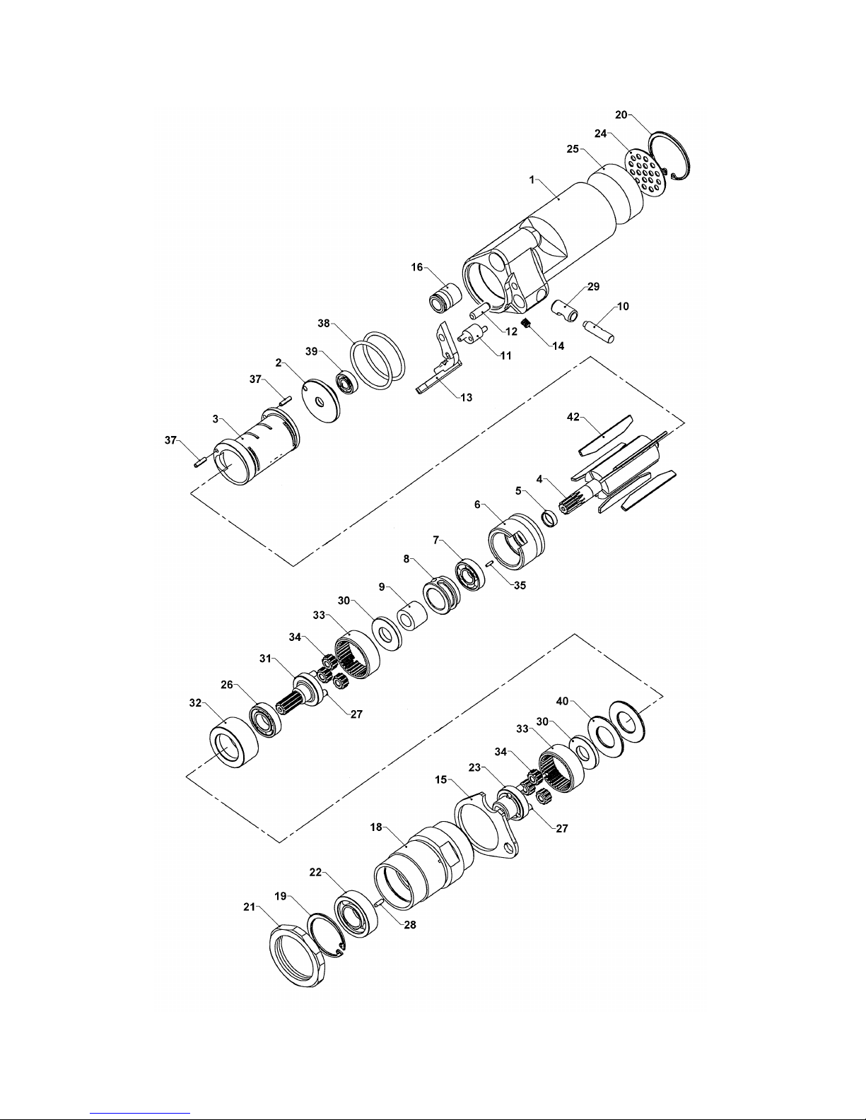
PARTS LIST, TENSION MOTOR 426887
KEY QTY PART NO DESCRIPTION
1 1 426124 MOTOR HOUSING
2 1 424154 BACK END PLATE
3 1 422815 CYLINDER
4 1 426136 ROTOR
5 1 024602 SPACER
6 1 425469 FRONT END PLATE
7 1 023481 BALL BEARING
8 1 426602 BRAKE
9 1 426145 ROLLER CLUTCH
10 1 426128 RELEASE PIN
11 1 426127 ECCENTRIC
12 1 423493 Ø5 X 16 DOWEL PIN
13 1 426611 LEVER
14 1 426138 LEVER SPRING
15 1 426126 COVER PLATE
16 1 423582 CAMOZZI CARTRIDGE
18 1 426137 MOTOR GEAR HOUSING
19 1 080315 32mm INT. RET. RING (TA# N5000-125)
20 1 424162 RETAINING RING
21 1 424166 LOCK NUT
22 1 023547 BALL BEARING
23 1 425159 IDLER CARRIER (2ND)
24 1 424165 MUFFLER PLATE
25 1 424167 MUFFLER INSERT
26 1 306396 BALL BEARING
27 6 251299 Ø4 X 12 DOWEL PIN
28 1 090065 LOCK PIN
29 1 426610 SLEEVE
30 2 423151 WASHER
31 1 423892 IDLER CARRIER (1ST)
32 1 424157 SPACER
33 2 422870 RING GEAR
34 6 422869 IDLER
35 1 090079 Ø1/16" X 1/4" DOWEL PIN
37 2 424164 Ø2.5 X 10 ROLL PIN
38 2 424172 O-RING SAE# 125
39 1 424161 BALL BEARING
40 2 014541 BELLEVILLE SPRING
42 5 422818 VANE
24
Page 25
25
Page 26
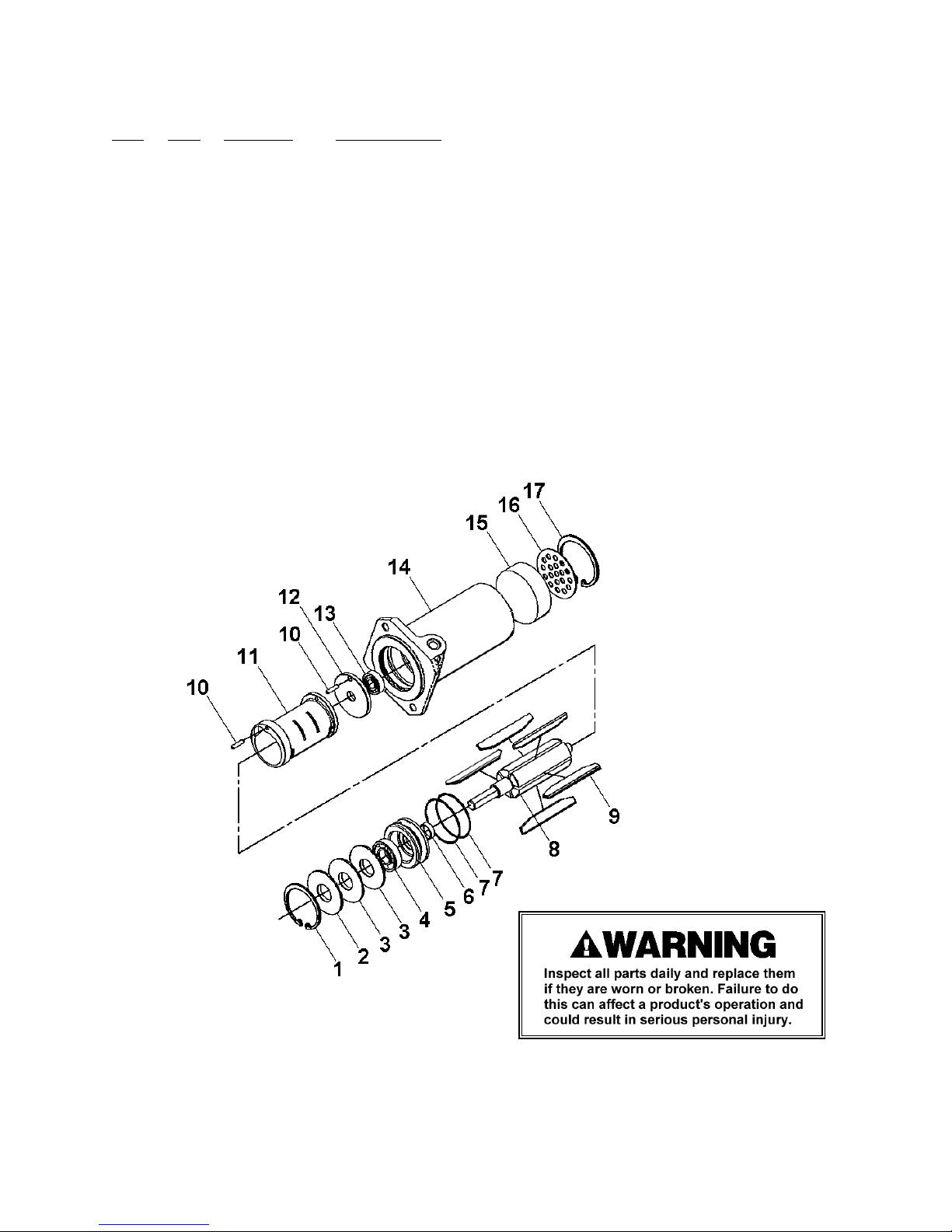
PARTS LIST, WELD MOTOR 423980
KEY QTY PART NO DESCRIPTION
1 1 080315 RETAINING RING
2 1 424181 FLAT WASHER
3 2 014541 BELLEVILLE WASHER
4 4 090118 BALL BEARING
5 1 423973 FRONT END PLATE
6 1 024602 SPACER
7 2 424172 O-RING
8 1 424174 ROTOR
9 5 422818 VANE
10 2 424164 LOCK PIN
11 1 422815 CYLINDER
12 1 424154 BACK END PLATE
13 1 424161 BALL BEARING
14 1 423919 MOTOR HOUSING
15 1 424759 MUFFLER INSERT
16 1 424165 MUFFLER PLATE
17 1 424162 RETAINING RING
26
Page 27
TROUBLESHOOTING
The following items are the most common types of tool malfunctions. For symptoms or remedies
not shown, contact your Signode service representative for additional information and details. The
following tool conditions are shown in this manual:
AIR SUPPLY
#1 - The air motor is frozen.
#2 - A leaking or sticking air valve.
#3 - The tool runs sluggishly.
TENSIONING
#4 - Feedwheel milling on strap and/or strap breaking.
#5 - The top strap is being properly tensioned but the tool does not hold the bottom strap.
WELDING
#6 - A poor weld identified by an incomplete area of weld.
#7 - Incomplete or no weld.
#8 - Strap is over welded.
#9 - Motor shut-off is sluggish.
#10 - Strap weld time is erratic.
#11 - Weld time is too long.
CUT-OFF ACTION
#12 - The cut-off has become difficult.
#13 - Weld strap is misaligned.
#1 CONDITION: The air motor is frozen.
CAUSE REMEDY
The motor is dry, hindering it from providing
maximum performance.
Add several drops of oil into the motor through the
air inlet. Hook the tool up to air, depress and hold the
operating lever while gently tapping the motor with a
rubber mallet. Repeat this procedure several times if
necessary.
#2 CONDITION: Air valve leaking or sticking.
CAUSE REMEDY
Worn, damaged or dirty O-rings on valve assemblies. Clean and lubricate the valve assemblies and the
valve sleeve assembly. Replace the O-rings on the
valve assemblies if necessary.
27
Page 28
TROUBLESHOOTING, Continued
#3 CONDITION: The tool runs sluggishly.
CAUSE REMEDY
1. The air filter-regulator-lubricator is
malfunctioning or is not properly maintained.
2. The tool may run sluggishly due to a clogged or
dirty motor filter screen due to a lack of properly
filtered air supply.
3. The tool may run sluggishly due to an improper
air motor adjustment or a clogged or dirty
vibrator assembly.
4. The end plates, pinion teeth on the rotor and the
rotor blades are worn, dirty or rusted.
1A. Check the regulator to see that the correct air
pressure is getting to the tool.
1B. Check to see the filter unit is clean and
functioning properly.
1C. Examine the lubricator to see there is oil in the
bowl and that oil is seen dripping from the sight
dome as the tool operates. This assures the air
motor is being properly lubricated.
2. Remove the Hansen plug at the inlet to the air
motor and examine the filter screen in the filter
assembly and clean it if necessary.
3. Clean vibrator parts as needed. Inspect vibrator
eccentric for wear or damage. Replace as
required.
4. Carefully remove the air motor from the tool and
disassemble it. If these parts are only dirty,
clean, thoroughly oil and reassemble. If they
are worn or rusted, replace them.
#4 CONDITION: Feedwheel milling on strap and/or strap breaking.
CAUSE REMEDY
1. Feedwheel is clogged with dirt or strap residue.
1. Clean teeth on feedwheel with the cleaning
brush (Signode Part No. 023963) provided.
2. Worn teeth on the feedwheel.
3. Excessive or improperly set feedwheel to gripper
plug clearance.
2. Replace the feedwheel.
3. Adjust feedwheel gap as required.
#5 CONDITION: The top strap is being properly tensioned but the tool does not hold the
bottom strap.
CAUSE REMEDY
1. The gripper plug may be packed with dirt or strap
residue preventing the teeth from penetrating the
strap.
2. Worn teeth on the gripper plug.
3. The tension release lever is being held while
operating the tool.
1. Clean teeth on gripper plug with the cleaning
brush (Signode Part No. 023963) provided.
2. Replace the worn plug. Since the feedwheel and
gripper plug are prevented from contacting one
another by an inside shoulder on each part, it is
not often these parts have to be replaced.
3. Review the operating instruction shown in this
manual.
28
Page 29
#6 CONDITION: A poor weld identified by an incomplete area of weld.
CAUSE REMEDY
Welding is achieved by a combination of vibration and
downward pressure of the upper gripper. Either a
restriction of motion or a reduction of downward
pressure will cause a poor weld.
#7 CONDITION: Incomplete or no weld.
CAUSE REMEDY
1. Improperly set weld time adjustment.
2. Worn teeth on upper or lower weld pads.
3. Insufficient air supply pressure.
4. Worn o-ring on main piston.
#8 CONDITION: Strap is over welded.
CAUSE REMEDY
Dismantle and clean the weld mechanism by brushing
away the strap residue or washing the entire unit in a
solvent. When a solvent is used it is imperative the
assembly be blown dry to remove all solvent. Check
for dry or worn bearings. Replace or lubricate as
required. If the tool has been used extensively,
examine the teeth on the upper and lower weld pads
for wear. Replace if worn.
1. Adjust weld time as required per instruction in
this manual.
2. Replace as required.
3. Remedy as required.
4. Replace as required.
Improper weld timing adjustment. Decrease weld timing as needed.
#9 CONDITION: Motor shutoff appears sluggish.
CAUSE REMEDY
1. Air leakage in timing circuit.
2. Dirty or very dry pilot valve (Key 106).
3. Dirty or very dry sealer valve stem (key 72).
1. Check o-rings and pneumatic components for
leaks. Replace parts as required.
2. Remove, clean and lubricate the pilot valve
using air line oil or replace if needed.
3. Remove valve stem and inspect o-rings for
damage. Replace o-rings as needed. Clean part
and lubricate with EP Accrolube grease.
29
Page 30
TROUBLESHOOTING, Continued
#10 CONDITION: Strap weld time is erratic.
CAUSE REMEDY
1. Air leakage in timing circuit.
2. Dirty or very dry pilot valve (Key 106).
3. Weld time flow control (Key 88) is contaminated
with debris or oil.
1. Check o-rings and pneumatic components for
leaks. Replace parts as required.
2. Remove, clean and lubricate the pilot valve
using air line oil or replace if needed.
3. Remove part and clean using dry compressed
air.
#11 CONDITION: Weld time is too long.
CAUSE REMEDY
Too much oil in the air supply system of the tool. Purge the tool of all excess oil.
#12 CONDITION: The cut-off has become difficult.
CAUSE REMEDY
1. Strap residue jamming cutter mechanism.
2. Cutter blade worn or damaged adjustability.
1. Clean parts as required.
2. Replace as required.
#13 CONDITION: Welded strap is misaligned.
CAUSE REMEDY
1. The tool is not being operated properly.
2. Teeth of upper weld gripper (Key 62) or lower
weld gripper (Key 50) are damaged.
3. Teeth of feedwheel (Key 47) or tension gripper
(Key 48) are damaged.
1. Review operating instruction shown in this
manual for proper operation of tool.
2. Replace damaged parts as needed.
3. Replace damaged parts as needed.
30
Page 31

MAINTENANCE
TOOL
1. Clean the teeth on the feedwheel and the gripper plug with the special brush provided.
3. Periodically clean the tool with compressed air.
4. Disassemble, clean and lubricate the welding mechanism.
GEAR HOUSING
Periodically check the gear housing portion of the tool:
1. Remove the end cap from the front of the gear housing by removing the set screw and pulling
the end cap off.
2. Check for adequate lubrication and wear of the Spiroid worm gear and ring gear.
3. This portion of the tool should be one-third full of gear grease.
4. Reinstall the end cap.
31
Page 32
OVERHEAD SUSPENSION
To work effectively, your VT tool must be properly installed. This installation includes, in some
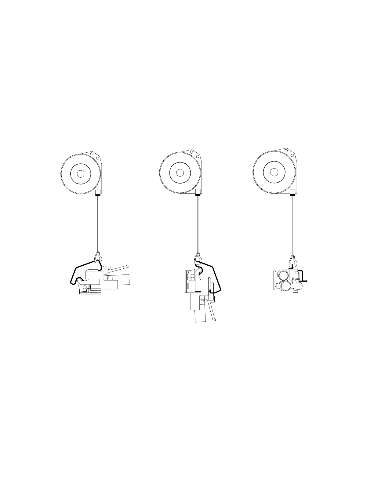
cases, proper suspension of the tool over the container to be strapped, and the proper placement
of a strapping dispenser to provide a continuous easy supply of strapping for the application. The
VT can be suspended in various operating positions by using the proper tool hanger and
hardware.
Review the illustrations below for the appropriate configuration for the tool application.
Applications are recommended to use an Overhead Tool Balancer as shown (Signode Part No.
306809).
HORIZONTAL SEALING
(USING OPTIONAL
3-WAY HANGER
TOP SEALING
VERTICAL SEALING
P/N 425235)
32
Page 33
TOOL OPTIONS
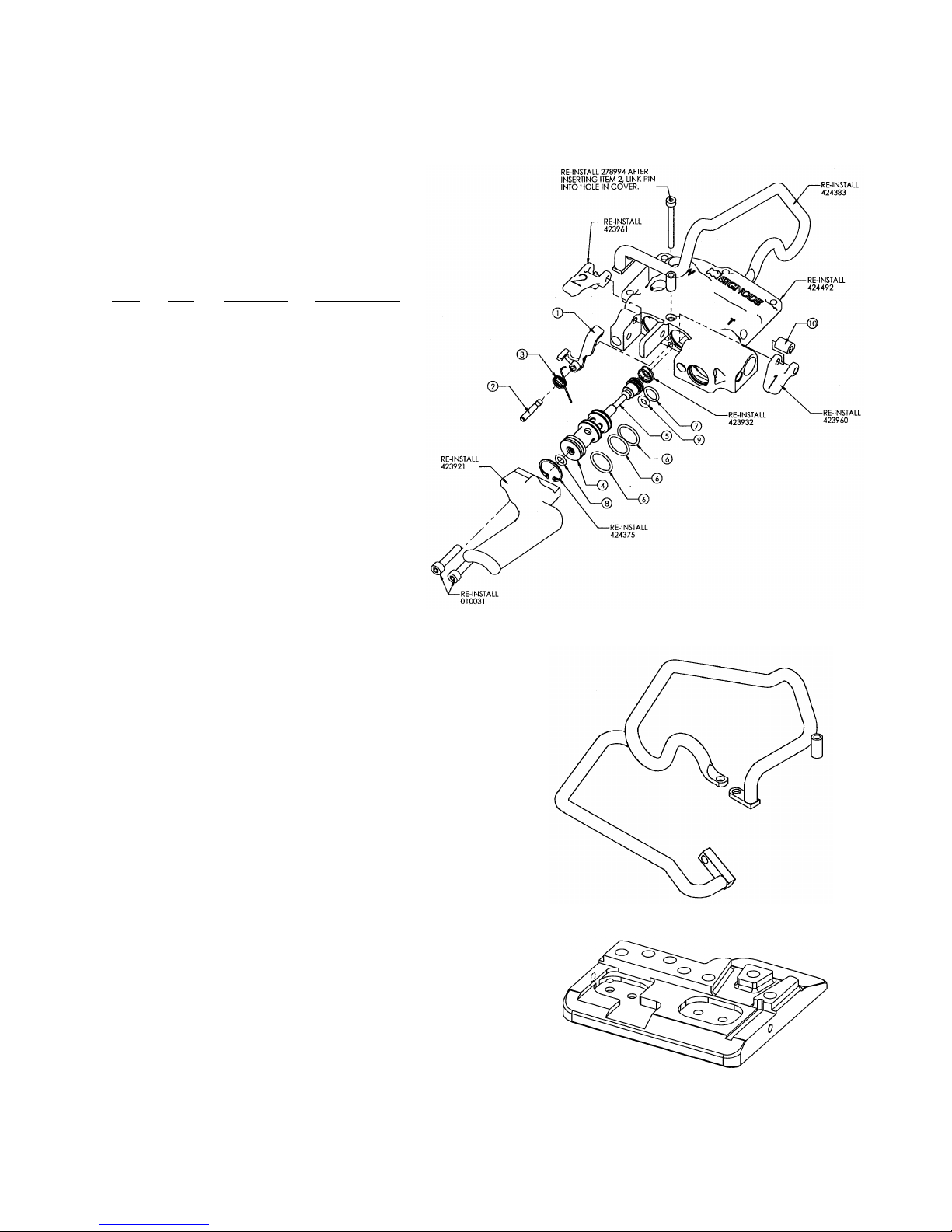
TENSION LATCH KIT, 424760
This option makes the VT tool easier for the operator to
use. The tension control lever only needs to be pressed
one time to fully tension a load. This option eliminates the
need to hold down the tension control for the entire tension
cycle. Once the tool’s sealer control in engaged the tension
latch automatically releases and resets.
Key Qty Part No. Description
1 1 424568 Catch link
2 1 424564 Link pin
3 1 424570 Link spring
4 1 424566 Tension valve sleeve
5 1 424567 Tension valve stem
6 3 022789 O-Ring, #016
7 1 023446 O-Ring, #012
8 1 091624 O-Ring, #010
9 1 424762 O-Ring, #106
10 1 424563 Link cylinder
3-WAY TOOL HANGER, 425235
This option allows the operator to suspend the VT tool
from its side to allow for easier horizontal strapping
applications as well as top and side sealing applications.
The hanger replaces the standard VT tool hanger.
NOTE: Hanger is supplied with additional M5x16 socket
head cap screws (Part No. 170304) for mounting the
hanger to the tool.
HEAVY DUTY TOOL BASE, 424763
This optional tool base replaces the standard base of the
VT tool. The heavy duty base is recommended for
increasing tool life in rough operating conditions. This part
is replaced using the existing mounting hardware of the
standard tool base.
33
Page 34
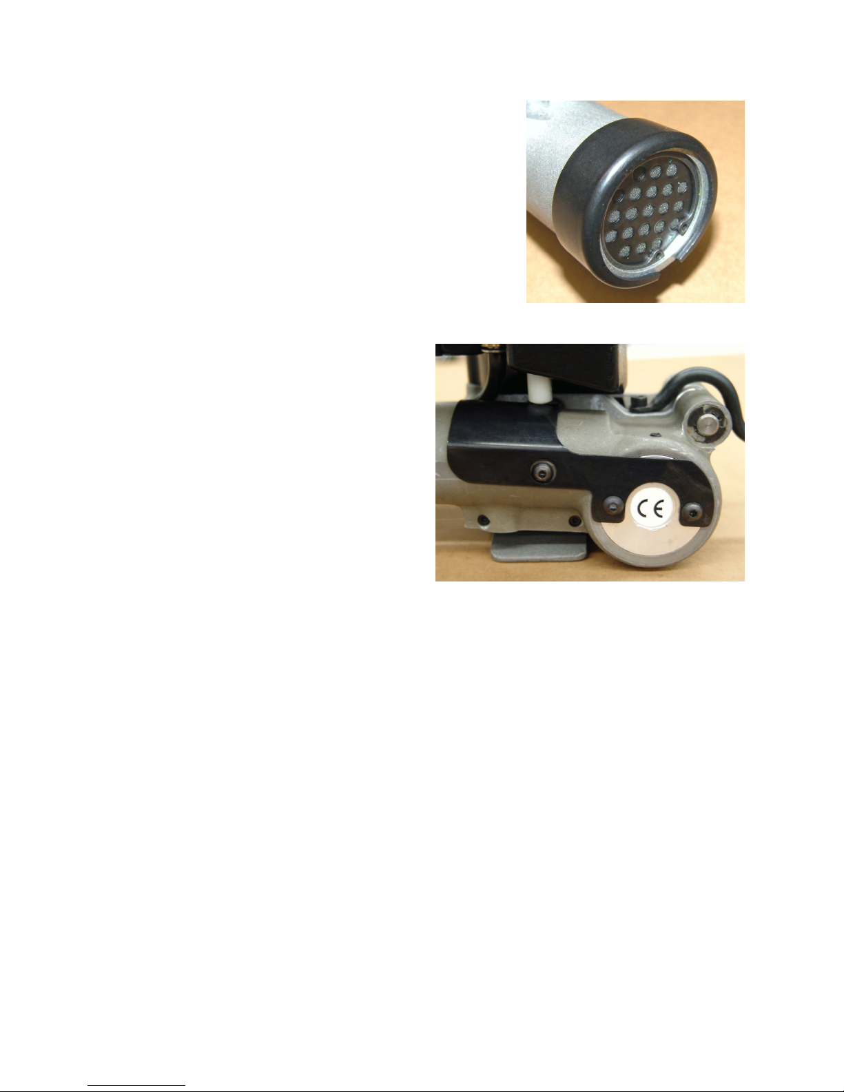
OPTIONAL WEAR RING, 424756
An optional wear ring is available to protect the tension motor
from harsh operating environments. This wear ring can be used
with either the VT-16 or the VT-19 tools. To install the wear ring
spread open the ring gap using an appropriate spreading tool.
Begin to slip the ring over the end of the tension motor. Using a
rubber mallet, gently tap the wear ring down onto the end of the
air motor.
OPTIONAL MOTOR GUARD, 425225
An optional motor guard is available to protect the
motor gear housing from harsh operating
environments. This motor guard can be used with
either the VT-16 or the VT-19 tools. Install the
motor guard to the bearing cap using two M5 x 8
button head cap screws. The white tension piston
must be raised by hand to install the guard under
piston. Once properly installed, the tension piston
should contact the motor guard.
34
Page 35

EU Declaration of Conformity
The Supply of Machinery (safety) Regulations
1992 (S.I. 1992/3073)
It is hereby declared that the undermentioned machinery has been designed and
constructed to comply with the health and safety requirements defined in EC Directive
89/392/EEC
Machine Supplier: Signode, Division of ITW Ltd.
Queensway, Fforestfach
Swansea SA5 4ED
Machine Description: VT Series
Machine Type: Pneumatic Combination Hand Strapping tool.
Provisions with which machine complies:
89/392/EEC, 91/368/EEC
Harmonized EuroNorms with which machine complies:
EN 292:1, EN 292:2, EN 294, EN 349
Technical Standards with which machine complies:
NA
Signature: Date: 4 June 2003
(Peter Oseland)
35
Page 36
SIGNODE
NEW TOOL WARRANTY
Signode Engineered Products Warrants that a new Signode strapping tool will operate per functional
specifications for a period of sixty (60) days after the date of shipment to the owner's place of business.
Normal wearing parts, as outlined in the Operation, Parts & Safety manual, are covered by a thirty (30) day
warranty unless, in Signode's judgement, these parts have been subjected to abnormal or extreme usage.
Signode's sole liability hereunder will be to repair or replace, without charge, F.O.B. Signode's Glenview,
Illinois plant, any tool which proves to not operate per functional specifications within the stated period.
Signode reserves the right to replace any tool which proves not to operate per functional specifications
with a new or like-new tool of the same model if in Signode's judgement such replacement is appropriate.
Any new replacement tool provided to an owner will carry a full sixty (60) day warranty. Any warranty
repaired tool or like-new replacement tool will carry a warranty for the balance of the time remaining on the
initial sixty (60) day warranty. This warranty will be extended to compensate for the time the tool is in
Signode's possession for warranty repairs.
This warranty is void as to any tool which has been: (I) subjected to mis-use, misapplication, accident,
damage, or repaired with other than genuine Signode replacement parts, (II) improperly maintained, or
adjusted, or damaged in transit or handling; (III) used with improperly filtered, unlubricated air or improper
strapping material, (IV) in Signode's opinion, altered or repaired in a way that affects or detracts from the
performance of the tool.
SIGNODE MAKES NO WARRANTY, EXPRESSED OR IMPLIED, RELATING TO MERCHANTABILITY,
FITNESS OR OTHERWISE EXCEPT AS STATED ABOVE AND SIGNODE'S LIABILITY AS ASSUMED ABOVE
IS IN LIEU OF ALL OTHERS ARISING OUT OF OR IN CONNECTION WITH THE USE AND PERFORMANCE
OF THE TOOL. IT IS EXPRESSLY UNDERSTOOD THAT SIGNODE SHALL IN NO EVENT BE LIABLE FOR
ANY INDIRECT OR CONSEQUENTIAL DAMAGES INCLUDING, BUT NOT LIMITED TO, DAMAGES WHICH
MAY ARISE FROM LOSS OF ANTICIPATED PROFITS OR PRODUCTION, SPOILAGE OF MATERIALS,
INCREASED COSTS OF OPERATION OR OTHERWISE.
Considerable effort has be made to ensure that this product conforms to our high quality standards.
However, should you experience any difficulties, please contact your Sales Representative providing
samples and the manufacturing code specified on the tool.
Thank you for your help.
SIGNODE ENGINEERED PRODUCTS
Hand Tool Division
3620 W. Lake Avenue, Glenview, Illinois 60025
© Copyright 2006, Signode 439992 Rev. 9/2006
 Loading...