

Signode TENSION-WELD VXL-2000-Z, TENSION-WELD VXM-2000-Z Operation, Parts And Safety Manual

VXL-2000-Z and VXM-2000-Z
TENSION-WELD®
STRAPPING TOOLS
READ THESE INSTRUCTIONS CAREFULLY.
FAILURE TO FOLLOW THESE INSTRUCTIONS CAN RESULT IN SEVERE PERSONAL INJURY.
GENERAL SAFETY CONSIDERATIONS
1. STRAP BREAKAGE HAZARD.
Improper operation of the tool or sharp corners on the load can result in strap
breakage during tensioning, which could result in the following:
! A sudden loss of balance causing you to fall.
! Both tool and strap flying violently towards your face.
Failure to place the strap properly around the load or an unstable or shifted load could result in
a sudden loss of strap tension during tensioning. This could result in a sudden loss of
balance causing you to fall.
Read the tool's operating instructions. If the load corners are sharp use edge protectors.
Place the strap correctly around a properly positioned load.
! Positioning yourself in-line with the strap, during tensioning and sealing, can result in
severe personal injury from flying strap or tool. When tensioning or sealing, position
yourself to one side of the strap and keep all bystanders away.
! Using strap not recommended for this tensioner can result in strap breakage during
tensioning. Use the correct Signode products for your application.
2. TRAINING.
This tool must not be used by persons not properly trained in its use. Be certain that you
receive proper training from your employer. If you have any questions contact your Signode
Representative.
3. EYE INJURY HAZARD.
Failure to wear safety glasses with side shields can result in severe eye injury or
blindness. Always wear safety glasses with side shields which conform to ANSI
Standard Z87.1 or EN 166.
4. FALL HAZARD.
Maintaining improper footing and/or balance when operating the tool can cause you to fall. Do
not use the tool when you are in an awkward position.
5. CUT HAZARD.
Handling strap or sharp parts could result in cut hands or fingers. Wear protective
gloves.
6. TOOL CARE, MAINTENANCE & PARTS REPLACEMENT.
! Take good care of the tool. Inspect and clean it daily, lubricate it weekly and adjust when
necessary. Replace any worn or broken parts.
! ALWAYS disconnect the pneumatic connection to the tool when performing part removal
and replacement procedures. NEVER connect a pneumatic source to a disassembled tool
unless otherwise specified.
7. WORK AREA.
Keep work areas uncluttered and well lighted.
2
Several types of strap can be used with this tool. Use the correct Signode products for your
application. If you need help contact your Signode Representative.
Signode tools and machines are designed and warranted to work together with Signode
strapping and seals. Use of non-Signode strap, seals and/or manufactured or specified
replacement parts may result in strap breakage or joint separation while applying strapping
to a load or during normal shipping and handling. This could result in severe personal injury.
SAFETY PROCEDURES FOR TOOL OPERATION
1. Before using this tool, read its Operation and Safety instructions.
! Do not exceed the operating air pressures stated elsewhere in the manual.
! Use Signode's approved filter-regulator-lubricator unit (P-008559).
! Never operate a pneumatic tool with a bottled air or gas source.
! For tension adjustments, follow instructions in this manual. For all other adjustments,
repairs or cleaning of the tool, disconnect air supply.
! This tool is a Tension Weld® type sealer. A properly made joint
will appear as shown in the illustration. If the joint does not
appear as shown, then the operator must proceed as follows:
A. Insure that the tools operating instructions are
being followed before applying another strap.
B. Cut the strap off and apply another.
If the joint still does not appear as shown, then inspect the tool for worn and/or damaged parts.
Replace tool parts as needed. NEVER HANDLE OR SHIP ANY LOAD WITH IMPROPERLY FORMED
JOINTS. Misformed joints may not secure the load and could cause serious injury.
! Tuck strap end back into the dispenser when not in use.
CUTTING TENSIONED STRAP
Use only cutters designed for cutting strap; never use claw hammers, crowbars, chisels, axes or
similar tools. Such tools will cause the strap to fly apart with hazardous force. Before using any
Signode product, read its Operation and Safety Manual.
3
TABLE OF CONTENTS
General Safety Instructions 2
Specifications 4
Air Line Piping Installation 5
Operating Instructions 8
Adjustments 10
Parts Removal and Replacement 12
Air Logic and Diagram 20
Air Motor Identification 21
Parts List, Air Motors 22
Parts List, Tool 28
Troubleshooting 30
Maintenance 34
Tool Options 35
EU Declaration of Conformity 39
Maximum operating air pressure is 90
psig (6.2 bar).
Strap could possibly break at less than
90 psig (6.2 bar) depending on strap
size and type of package.
VXL-2000-Z VXM-2000-Z
Part No. 306540NT Part No. 306541NT
SPECIFICATIONS
MODEL
TYPE WIDTH THICKNESS
VXL-2000-Z {302}, {304}, 306 Dymax
{502}, {504}, 506, 508 Dymax
{714}, {716}, 718 Contrax
{814}, {816}, 818 Contrax
{1716}, 1718 Tenax
{1816}, 1818, 1822 Tenax
VXM-2000-Z {304}, 306 Dymax
{504}, 506, 508 Dymax
{716}, 718 Contrax
{816}, 818 Contrax
{1716}, 1718 Tenax
{1816}, 1818, 1822 Tenax
NOTE: Strap sizes shown in brackets { } indicates strap sizes that (due to tension capabilities) may
require use of the VXL model only or the use of Tension Control Kit (Signode Part No. 422540
shown on page 33). Successful use of these strap sizes depends upon air pressure, tool condition
and package characteristics.
STRAP
7/16"(10.5mm)
1/2"(12.7mm)
7/16"(10.5mm)
1/2"(12.7mm)
7/16"(10.5mm)
1/2"(12.7mm)
7/16"(10.5mm)
1/2"(12.7mm)
7/16"(10.5mm)
1/2"(12.7mm)
7/16"(10.5mm)
1/2"(12.7mm)
0.017" to 0.029" (.43-.73mm)
0.015" to 0.030" (.38-.76mm)
0.019" to 0.030" (.48-.76mm)
0.017" to 0.026" (.43-.66mm)
0.021" to 0.024" (.53-.60mm)
0.017" to 0.028" (.43-.71mm)
0.023" to 0.029" (.58-.73mm)
0.020" to 0.030" (.50-.76mm)
0.025" to 0.030" (.63-.76mm)
0.022" to 0.026" (.55-.66mm)
0.021" to 0.024" (.53-.60mm)
0.017" to 0.028" (.43-.71mm)
4
PNEUMATIC INFORMATION
AIR PRESSURE REQUIREMENTS
The VXL/VXM tools are designed to operate at air pressures ranging between 70 and 90 psig (4.8 -
6.2 Bar). Operating these tools outside this pressure range could result in strap breakage due to
over tensioning or poor quality welds.
AIR PRESSURE VS. PERFORMANCE
The air pressure supplied to the VXL/VXM tools must be a minimum of 70 psig (4.8 Bar) If the air
supply pressure can be adjusted within a range from 70 psi to 90 psi (4.8 - 6.2 Bar) the tool's
performance can be fine tuned to a particular application or operation preferences. Raising the
VXL/VXM air supply pressure to the tool will directly alter the rate at which the tool will take-up the
strap slack and the strap tension. Increasing or decreasing the VXL/VXM air supply within the
suggested 70 to 90 psig (4.8-6.2 Bar) range will not seriously affect the actual welding portion of
the strap cycle.
After an initial "Break-In" period, the air motor may become more powerful. If the tool's
performance is effected by this increase in performnace, reduce the air pressure at the regulator
as required (but not below 70 psig).
AIR SUPPLY INSTALLATION
If compressor has a good dryer unit, use black pickled pipe. When a dryer unit is not installed, use
galvanized or copper pipe. To perform reliably, a pneumatic tool requires a continuous source of
clean, water-free air at adequate pressure.
Never operate this tool using a bottled air or gas source.
Bottled air/gas sources do not provide consistant operating pressure.
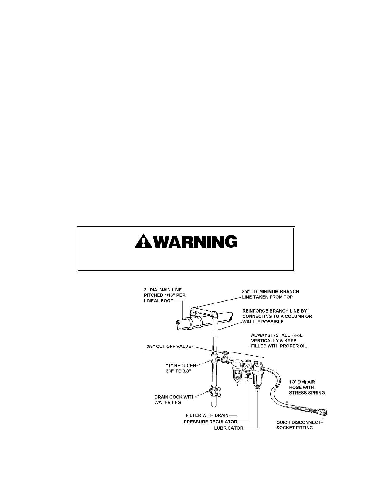
A filter-regulator-lubricator unit
(Signode P/N 008559) must be
installed as close to the air tool as
possible, preferably within 10
feet. It should be placed in a
convenient location where it can
easily be drained, adjusted, and
filled with oil. The air hose
(Signode P/N 008558) must have
at least a 3/8" I.D. A quickconnect press-on socket
(Signode P/N 008569) is installed
on the stress spring end of the
hose for convenient hookup to
the air tool.
5

PNEUMATIC INFORMATION, Continued
Filter and lubricator bowls are made of polycarbonate material. Do not install where bowls may be
exposed to materials incompatible with polycarbonate. Certain oils, solvents, and chemicals or
their fumes can weaken these bowls and possibly cause them to burst. Clean only with warm
water. A cut-off valve placed ahead of the filter will be useful when cleaning the filter or
replenishing the lubricator.
MOISTURE
Moisture is always present in air lines due to condensation within the lines as the air cools. Steps
must be taken to remove this moisture and to keep it from the air tool. This is because water tends
to wash away lubricants and cause corrosion, sticking and failure of internal parts.
The main line should be pitched so the far end terminates in a water leg. Branch lines are taken
from the top of the main, never off the bottom. Every branch should have a water leg at its lowest
point, with a drain cock which is drained daily.
If these precautions are taken and water is still present, an after cooler and a moisture separator
are required between the compressor and the air receiver tank. A large air line separator can be
installed in the air tool line, but precautions must be taken to insure that it will be drained daily,
before the air tool is operated.
Water in air lines is a constant threat to the proper operation of air tools. Even near freezing
operating conditions, a good refrigerant type dryer is essential. A good dryer will remove 95% or
more of water right at the compressor. The remaining moisture is removed at the water leg in the
piping system or in the filter (Signode Part No. 008559).
NOTE: Additional information is available in the Signode publication, "Air Supply Manual" (E-
186038). If you have any questions, contact your local Signode Representative.
LUBRICATION
The air motor must be properly lubricated. This is achieved by keeping the air line lubricator filled
with oil and correctly adjusted. Without proper lubrication, the motor will become sticky and the
tool will give low and erratic tension and be difficult to release from the strap.
Install the lubricator as close to the air tool as possible. The arrow on the lubricator's top surface
must point in the direction of air flow. For proper operation, oil must drop through the lubricator
sight glass at a rate of 1 to 4 drops per minute. This rate is checked while the air tool is running
free. Only 20% of this oil is actually delivered to the tool. The remaining oil drops back into the oil
reservoir. The unit is factory set and should require no adjustment. If an adjustment is required,
the adjusting screw on top of the lubricator may be turned as marked to reduce or increase the
flow of oil.
The correct grade of oil must be used in the lubricator; too heavy an oil will not provide sufficient
lubrication and will cause sticking and sluggish operation of the air tool. Recommended oils are
any good grade of rust and oxidation inhibiting oil with a viscosity of 80-120 S.U.S. at 100 degrees
Fahrenheit. (0.15 to 0.25 cm
2
/sec. at 38 degrees Celsius), such as:
Non Fluid Oil Co., grade #LS-1236 Signode oil - Part No. 008556
If necessary, use SAE #5 or SAE #10 non-detergent, cut 1 to 1 with kerosene.
NOTE: Some oils contain anti-wear additives which may disable the air motor. Be certain to use
recommended oil.
Several drops of lubricator oil added to the inlet of the air motor or into the air line each day will
help insure good operation. A noticeable reduction of air motor performance can usually be
corrected by squirting a few drops of oil into the air line.
6

STRAP TENSION
Strap tension is controlled by air pressure. Adjust the pressure regulator, within a range of 70 - 90
psig (4.8-6.2 bar), to provide the desired tension. Once the regulator is set the tension will be
uniform on all straps, provided the operator allows the air motor to stall. The air pressure gauge
must be accurate. Confirm calibration by comparing it to a master gauge.
The VXL-2000Z tool is factory tested to ensure that at least 90 lbs. (400N) of tension is drawn at 90
psig (6.2 bar) and the VXM-2000Z tool is factory tested to ensure that at least 140 lbs. (621 N) of
tension is drawn at 90 psig (6.2 bar).
Review the instructions on page 10 of this manual for information on how to adjust strap tension.
Strap breakage hazard.
Strap can break if inlet air pressure to tool exceeds 90 psig (6.2 bar).
Strap breakage can result in severe personal injury.
Maximum operating air pressure is 90 psig (6.2 bar).
AIR CONSUMPTION - Air consumption in cubic feet per minute (cfm) for the VXL/M can be
calculated as follows: cfm = (a) x (b) x (0.17)
a = Number of straps applied per minute.
b = Number of seconds motor is on per strap during tensioning, from start to deceleration
to stall including stall time while making joint.
0.17 = VXL/M efficiency ratio.
Example Calculation: Peak strapping load is 4 straps/min. so a = 4
Air motor is on 5 seconds/strap, so b = 5
VXL/M efficiency ratio is 0.17
(a)x(b)x(0.17)
4x5x0.28=5.6 cubic meters/hr. (5.6M
6 4x5x0.17=3.4 cubic ft/min.
3
/hr.)
Air pressure is assumed to be 90 psig (6.2 Bar) with recommended size and length of air hose.
Volume of air is at room temperature and sea level pressure, or so-called "free air" conditions. For
more detailed information about air supply systems refer to Signode manual Part No. 186038.
COLD WEATHER OPERATION
If a tool does not operate satisfactorily in freezing temperatures, certain steps can correct the
problem. The following steps can be taken to improve cold weather operation of the tool:
a. An air line dryer adjacent to the compressor.
b. Use lubricant recommended by Signode. Signode has tested the use of anti-freezes, none
work well in air tools; the tool will gum up when anti-freezes are introduced and will not
function properly. The best lubricant for freezing weather is the 1 to 1 oil and kerosene
combination.
c. If possible, run the air supply line to a indoor located Filter-Regulator-Lubricator or relocate the
F-L-R to a warmer operating area.
7
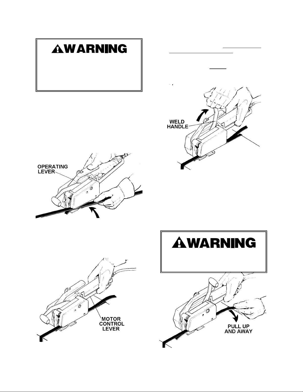
OPERATING INSTRUCTIONS
Wear safety glasses.
Stand to one side of the strap when
tensioning. Make sure all bystanders
are clear before proceeding.
1. With the dispenser placed behind you,
bring the strap over the top and around
the package, pulling out excess slack.
Press the operating lever with your right
hand and, with your left hand, insert the
overlapped straps under the feedwheel
and welding mechanism. Leave only a
short tail ahead of the feedwheel and
make sure straps are aligned behind the
tool. Do not make a joint over a void area
of the package.
3. When the motor stalls, indicating
completion of tension, continue to hold
the motor lever fully closed against the
motor housing and pull back the weld
handle with your left hand. The handle
should be pulled quickly
without hesitation. When the weld lever is
pulled back it traps the motor lever in the
ON position.
all the way back
2. Recheck the strap alignment at the rear
of the tool and realign if necessary.
Release the operating lever and, while
standing to one side of the strap line,
squeeze the motor control lever to
tension the strap.
4. The internal weld timer is energized. The
strap is welded and the supply end of the
strap is cut-off. Pull the cut strap away
during welding. The tool will continue
through the weld cycle and stop with the
motor lever being held in place. When the
timer times out, the weld action stops.
Allow the tool to remain stationary for at
least 3 seconds to ensure that the weld is
fully cooled.
Failure to wait 3 seconds can result
in an improperly formed joint which
may lead to joint separation.
5. Push the weld handle to the forward
8
position with your left hand. The motor
lever will return to the OFF position as
the weld handle is moved forward.
6. Press the operating lever and swing the
tool off the strap, rear of tool first. Inspect
the joint to make sure the straps have
been properly welded.
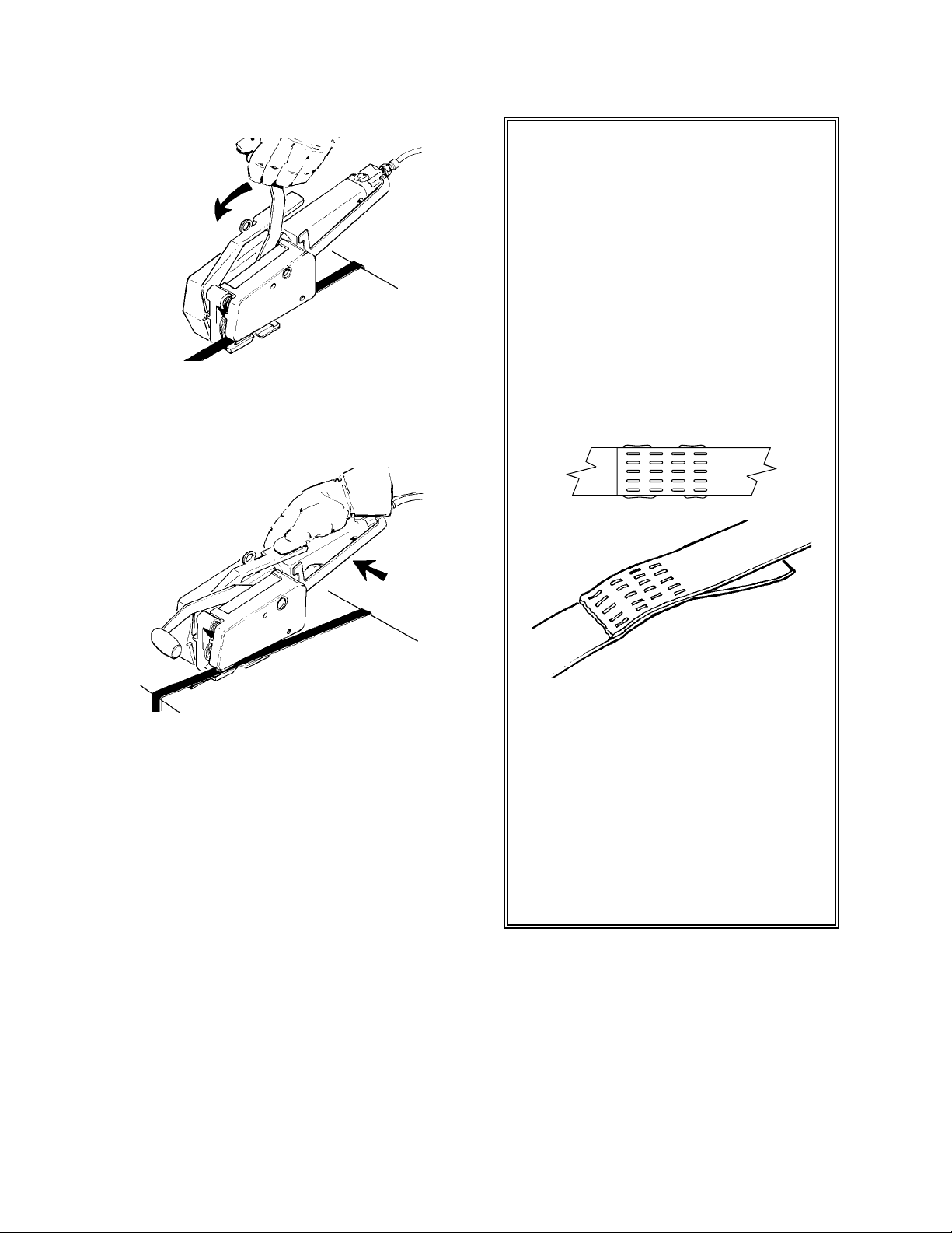
SEALING OPERATION
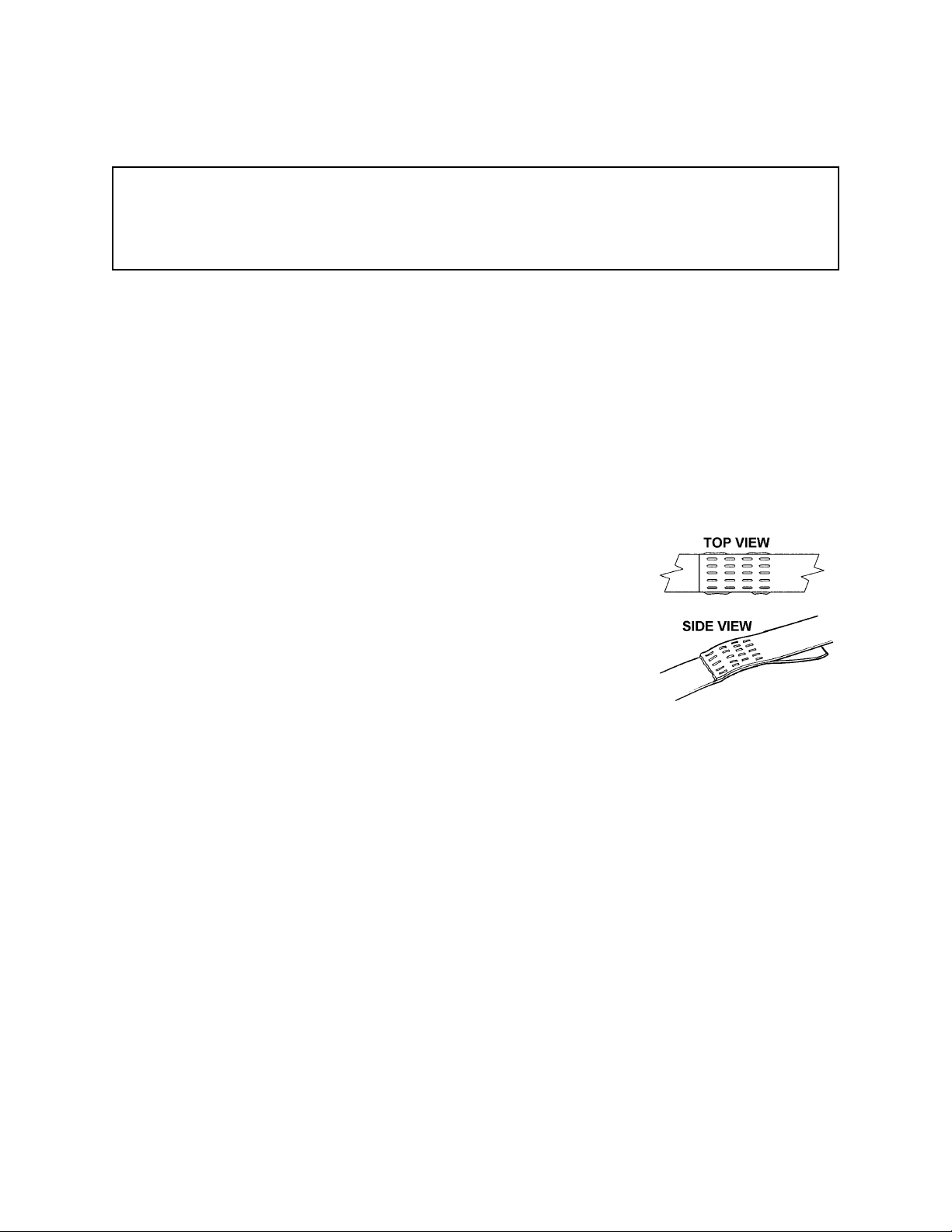
This tool is a Tension Weld® type
sealer. A properly made joint will
appear as shown in the illustration.
If the joint does not appear as shown,
then the operator must proceed as
follows:
1. Insure that the tools operating
instructions are being followed
before applying another strap.
2. Cut the strap off and apply another.
A good weld will show some material
displacement along the edges.
TOP VIEW
SIDE VIEW
The welded area should extend the
full length and width of the gripper
impression.
If the joint still does not appear as
shown, then inspect the tool for worn
and/or damaged parts. Replace tool
parts as needed. NEVER HANDLE OR
SHIP ANY LOAD WITH IMPROPERLY
FORMED JOINTS. Misformed joints
may not secure the load and could
cause serious injury.
9
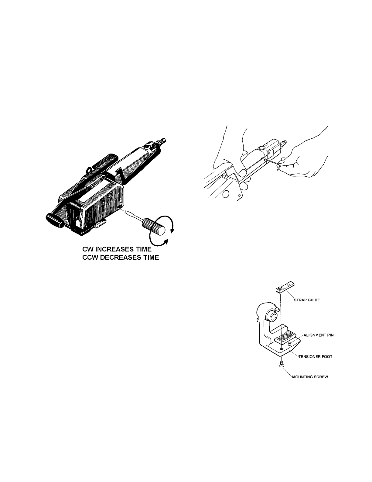
TOOL ADJUSTMENTS
WELD TIME
Weld time has been factory adjusted to
provide acceptable weld strength when using
Tenax (polyester) or Contrax (polypropylene)
type strap. When using Dymax (nylon) strap
the weld time must be increased.
Weld time may need to be adjusted due to air
supply differences, tool wear, etc.
Adjustments are made by turning the small
slotted screw, located beneath the weld
housing at the rear of the tool, using a small
screwdriver.
STRAP TENSION
Strap tension can be accurately controlled by
turning the adjustment screw in 1/4
increment turns counter-clockwise using a
3/32 hex wrench (P/N 422587) to reduce strap
tension and clockwise to increase strap
tension. Operating air pressure must be set
between 85 and 90 psi (5.7-6.2 Bar). With
accurately controlled air pressure the tension
will be uniform on all straps, provided the
operator allows the air motor to stall.
STRAP GUIDES
Establishing the correct weld time is a matter
of trial and error and should be conducted as
follows.
NOTE: Turning the adjustment screw
clockwise increases weld time and
counterclockwise decreases the weld time.
1. Adjust the screw in 1/8 to 1/4 turn
increments only.
2. Apply a strap and make a weld.
3. Compare the weld made with the
illustrations shown on page 9 of this
manual. A good weld will displace some
material along the outer edges of the
joint.
4. If you are unable to produce an
acceptable joint or if you have any
questions as to whether your tool is
producing good weld strength, contact your Signode Sales Representative.
The VXL/VXM tool is manufactured with a
strap guide for 7/16" (10.5mm) strap. When
using 1/2" (12.7mm) strapping material, the
standard strap guide must be replaced with
the 1/2" (12.7mm) strap guide for proper
strap alignment. One 1/2" (12.7mm) strap
guide is packaged with each VXL/VXM tool.
To remove a strap
guide from the tool,
remove the screw
from the bottom of
the tensioner foot.
Once the screw has
been removed the
strap guide can be
lifted over the
alignment pin and
out of the tool.
Replace the new
strap guide in the
same manner in
which the old guide
was removed.
10
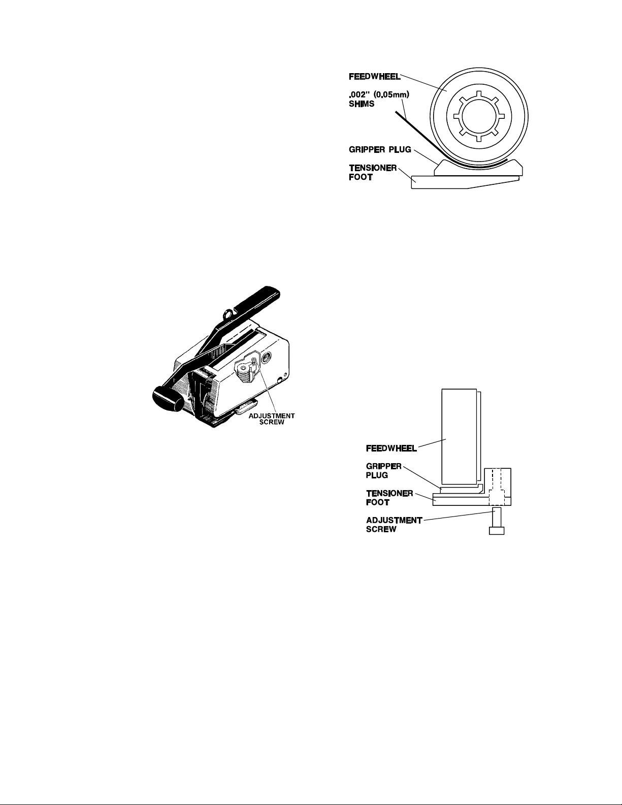
CUTTER ADJUSTMENTS
When the strap cutter begins to wear or
strapping seems difficult to cut off the strap
cutter may need adjustment. Contact the
Signode tool repair center or your Signode
representative for information on accessing
the adjustment screw.
Before attempting to adjust the cutter, first
place a single layer of strapping in the tool
and pull the weld handle to the full back
position.
Adjust the cutter blade position by turning
the adjustment screw inward (clockwise) or
out (counter-clockwise) using 1/8 turn
increments. Adjust the cutter blade so that
the cutting edge of the blade places a slight
impression into the single layer of strap.
Remove the
single layer of
strap. Run one
or more tool
cycles and
continue to
adjust the
cutter as
necessary until
proper strap
cut-off has
been obtained.
NOTE: Do not over tighten cutter mechanism
as lower strap damage or poor strap cut-off
will occur.
FEEDWHEEL TO GRIPPER PLUG
2. Release the tensioner foot to pinch the
shims between the feedwheel and the
gripper plug. Holding the shims with one
hand, jog the air motor on and off to
rotate the feedwheel at least one full
revolution. If properly adjusted the tool
should lightly tug at the shims while
rotating. Clearance between the
feedwheel and gripper plug at this point
should fall between .002"-.004" (.05.10mm).
3. If the feedwheel needs to be adjusted,
use a 3/32" hex wrench to rotate the
adjustment screw located in the
tensioner foot.
The feedwheel to gripper plug clearance may
require readjustment if the feedwheel,
tensioner foot or gripper plug has been
replaced. The feedwheel clearance should
also be inspected during routine tool
maintenance procedures. Adjust the
feedwheel clearance as follows:
1. Open the tensioner foot and place 1 to 2
layers of .002", 1/2" wide (.05 x 12mm)
shim stock between the feedwheel and
the gripper plug.
NOTE: Using a single .004" (.10mm) shim is
not recommended because a single thicker
shim may not conform to the feedwheel
shape, resulting in inaccurate clearance
measurements.
Turn the adjustment screw clockwise for
greater clearance and counter-clockwise
for less clearance. Turn the adjustment
screw only in 1/8 turn increments. After
each 1/8 turn, repeat the adjustment
testing as described in step 2.
4. Once the proper clearance has been
found the tool can be returned to service.
NOTE: Never turn out the adjustment screw
more than 1/8 turn at a time without testing
or completely removing the adjustment
screw. These actions will severely damage
both the feedwheel and gripper plug.
11
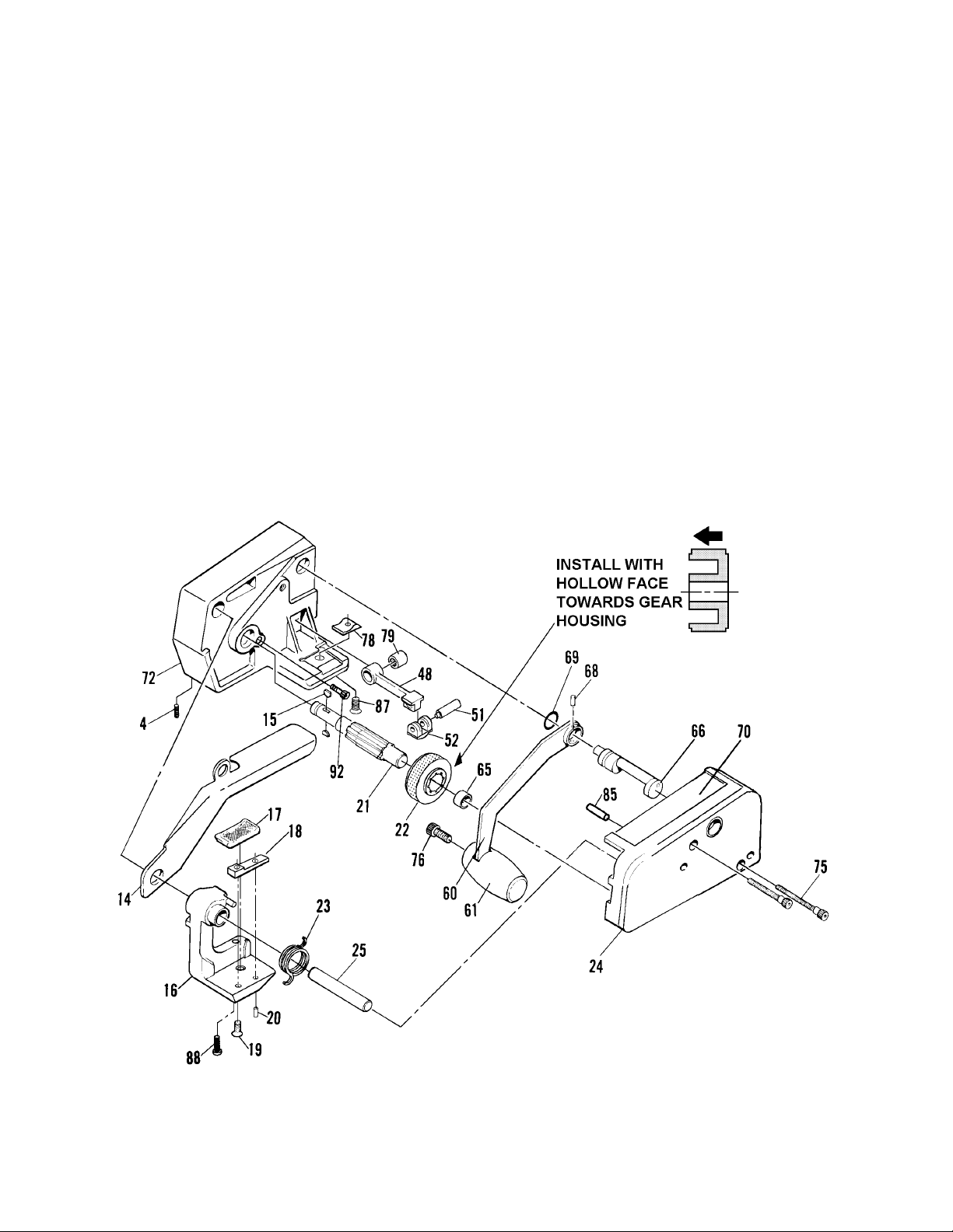
PARTS REMOVAL & REPLACEMENT
FEEDWHEEL AND GRIPPER PLUG
1. Place the tool on its side and remove the
two socket head cap screws (75) from the
weld housing (24).
2. Pull upward on the weld housing and
raise it slightly.
3. Insert a thin rod or screwdriver and
disengage the torsion spring (23) from
the tab on the weld housing (24).
4. Pull the weld housing off the tool.
5. Lift the feedwheel (22) from the feedwheel
shaft (21).
6. Lift the torsion spring (23) and the
tensioner foot (16) off the support pin
(25). This allows the gripper plug (17) to
be replaced if necessary. Turn the
tensioner foot over, remove the flat head
cap screw (19) and with a small punch,
drive the roll pin (20) upward to remove
the gripper plug and strap guide, (18).
7. Replace the feedwheel if necessary,
making sure the hollow face of the
feedwheel faces inward.
8. Lubricate the support pin and the end of
the feedwheel shaft with Mo-Lith No. 2
lubricant to allow the tensioner foot to
pivot freely.
9. Reassemble the parts in reverse order if
further parts removal and replacement
are not needed.
12
 Loading...