

Signode Tension-Weld BTS-16, Tension-Weld BTS-19, Tension-Weld BTS-25, Tension-Weld BTS-32 Operation, Parts And Safety Manual
Page 1
BTS-16/19/25/32
ENSION-WELD® STRAPPING TOOL
T
NOTE: Fully charge battery before first use of tool.
Page 2
READ THESE INSTRUCTIONS CAREFULLY. FAILURE TO FOLLOW THESE INSTRUCTIONS CAN RESULT IN
S
EVERE PERSONAL INJURY.
GENERAL SAFETY CONSIDERATIONS
1. STRAP BREAKAGE HAZARD
Improper operation of the tool or sharp corners on the load can result in strap breakage during
tensioning, which could result in the following:
! A sudden loss of balance causing you to fall.
! Both tool and strap flying violently towards your face.
Failure to place the strap properly around the load or an unstable or shifted load could result in a
sudden loss of strap tension during tensioning. This could result in a sudden loss of balance causing
you to fall.
Read the tool's operating instructions. If the load corners are sharp use edge protectors. Place the
strap correctly around a properly positioned load.
! Positioning yourself in-line with the strap, during tensioning and sealing, can result in severe
personal injury from flying strap or tool. When tensioning or sealing, position yourself to one side
of the strap and keep all bystanders away.
! Using strap not recommended for this tensioner can result in strap breakage during tensioning.
Use the correct Signode products for your application.
2. TRAINING
This tool must not be used by persons not properly trained in its use. Be certain that you receive
proper training from your employer. If you have any questions contact your Signode Representative.
3. EYE INJURY HAZARD
Failure to wear safety glasses with side shields can result in severe eye injury or
blindness. Always wear safety glasses with side shields which conform to ANSI Standard
Z87.1 or EN 166.
4. FALL HAZARD
Maintaining improper footing and/or balance when operating the tool can cause you to fall. Do not use
the tool when you are in an awkward position.
5. CUT HAZARD
Handling strap or sharp parts could result in cut hands or fingers. Wear protective gloves.
6. TOOL CARE
Take good care of the tool. Inspect and clean it daily, lubricate it weekly and adjust when
necessary. Replace any worn or broken parts.
7. WORK AREA
Keep work areas uncluttered and well lighted.
Several types of strap can be used with this tool. Use the correct Signode products for your application. If
you need help contact your Signode Representative.
CUTTING TENSIONED STRAP
Use only cutters designed for cutting strap; never use claw hammers, crowbars, chisels, axes or similar
tools. Such tools will cause the strap to fly apart with hazardous force. Before using any Signode product,
read its Operation and Safety Manual.
2
Page 3

SAFETY PROCEDURES FOR ELECTRIC TOOLS
1
. GUARD AGAINST ELECTRIC SHOCK
2. CONSIDER WORK AREA ENVIRONMENT
!!!! T
ry not to operate tool in damp or wet locations.
!!!! Prevent body contact with grounded surfaces, such as pipes, radiators, ranges, refrigerator
enclosures.
!!!! When tool is used outdoors, use only extension cords intended for outdoors and so marked.
!!!! Wear rubber gloves and non-skid footwear when working outdoors.
!!!! Do not expose power tools directly to rain.
!!!! Never operate tool in presence of gases or flammable liquids.
3. Never allow visitors to contact tool or extension cords. All visitors should be kept away from work
area.
4. DO NOT ABUSE TOOL
!!!! K
eep handle dry, clean and free from oil and grease.
!!!! Never carry tool by cord or yank it to disconnect from receptacle.
!!!! Always keep cord from heat, oil and sharp edges.
!!!! Always store idle tool in dry, high or locked-up place.
!!!! Always disconnect tool when not in use or before servicing.
!!!! To avoid unintentional starting, never carry plugged-in tool with finger on switch. Be sure switch
is off when plugging in.
5. MAINTAIN TOOL WITH CARE
Check Damaged Parts. Before further use of the tool, a guard or other part that is damaged should be
carefully checked to determine that it will operate properly and perform its intended function. Check
for alignment of moving parts, binding of moving parts, breakage of parts, mounting, and any other
condition that may affect its operation. A guard or other part that is damaged should be properly
repaired or replaced by an authorized service center unless otherwise indicated elsewhere in this
instruction manual. Have defective switches replaced by authorized service center. Do not use tool if
switch does not turn it on and off.
!!!! W
hen servicing double insulated tool, use identical replacement parts.
!!!! Keep tool clean for better and safer performance.
!!!! Inspect tool cord periodically and, if damaged, have repaired by authorized service facility.
!!!! Inspect extension cord periodically and replace if damaged.
SAFETY PROCEDURES FOR TOOL OPERATION
Before using this tool, read its Operation and Safety instructions. This tool is a Tension Weld® type sealer.
A properly made joint will appear as shown in the illustration. If the joint does not appear as shown, then
the operator must proceed as follows:
A. Ensure that the tools operating instructions are
being followed before applying another strap.
B. Cut the strap off and apply another.
If the joint still does not appear as shown, then inspect the tool for worn and/or damaged parts. Replace
tool parts as needed. NEVER HANDLE OR SHIP ANY LOAD WITH IMPROPERLY FORMED JOINTS.
Misformed joints may not secure the load and could cause serious injury. Tuck strap end back into the
dispenser when not in use.
3
Page 4
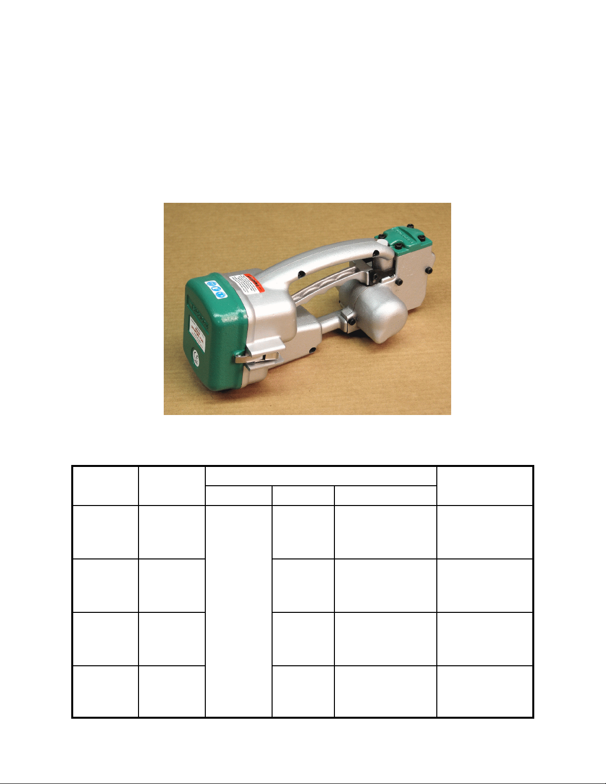
TABLE OF CONTENTS
Pa
ge
Page
General Safety Instructions 2
Specifications 4
Major Components 5
Battery Information 5
Operating Instructions 7
Weld Time Adjustments 9
Parts List 10
Troubleshooting 12
Tool Maintenance 13
SPECIFICATIONS
MODEL
(110 Volt)
BTS-16
(426500)
BTS-19
(426501)
BTS-25
(426502)
BTS-32
(427140)
MODEL
(220 Volt)
BTS-16
(429516)
BTS-19
(429519)
BTS-25
(429525)
BTS-32
(429532)
STRAP
TYPE WIDTH THICKNESS
16mm
(.629")
19mm
(.748")
High
Strength
Tenax
25mm
(1.000")
32mm
(1.250")
0.030" to 0.044"
(0.76-1.11mm)
0.045" to 0.055"
(1.14-1.40mm)
0.045" to 0.055"
(1.14-1.40mm)
0.040" to 0.050"
(1.00-1.30mm)
RECOMMENDED
TENSIONER
Signode PT-16
Signode PT-19
Signode PT-25
Signode PT-32
4
Page 5
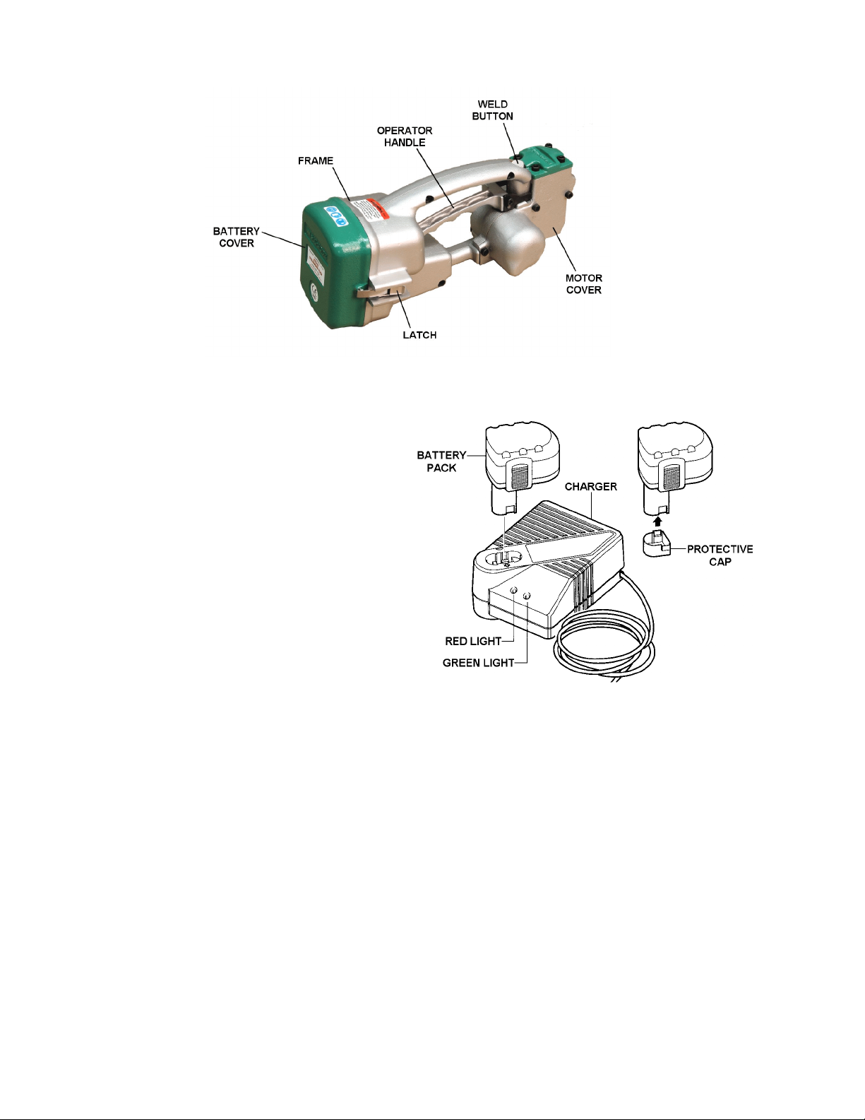
MAJOR COMPONENTS
B
ATTERY INFORMATION
Before attempting to us this tool make sure the
batteries are properly charged. A discharged
battery may result in a poor weld or no weld
condition.
1. The battery pack accepts only about 80% of
its maximum capacity with its first few
charge cycles. However, after the first few
charge cycles, the battery will charge to full
capacity.
2. The charger was designed to fast charge the
battery only when the battery temperature is
between 40/F (4/C) and 105/F (41 OC).
3. A substantial drop in operating time per charge may mean that the battery pack is nearing the end of
its life and should be replaced.
4. If you anticipate long periods (i.e. a month or more) of non-use of your tool, it is best to run your tool
down until it is fully discharged before storing your battery pack. After a long period of storage, the
capacity at first recharge will be lower. Normal capacity will be restored in two or three
charge/discharge cycles. Remember to unplug charger during storage period.
5. If battery does not charge properly:
A. Check for voltage at outlet by plugging in some other electrical device.
B. Check to see if outlet is connected to a light switch which turns power "off"when lights are turned
off.
C. Check battery pack terminals for dirt. Clean with cotton swab and alcohol if necessary.
5
Page 6
BATTERY INFORMATION, Continued
I
NDICATORS, SYMBOLS AND MEANING
If the indicator lights are "OFF", the charger is not receiving power from power supply outlet.
If the green indicator light is "ON", the charger is plugged in but the battery pack is not
inserted, o the battery pack is fully charged and is being trickle charged
If the green indicator light is "BLINKING", the battery pack is being fast-charged. Fastcharging will automatically stop when the battery pack is fully charged.
If the red indicator light is "ON", the battery pack is too hot or cold for fast-charging. The
charger wi I switch to trickle charge, until a suitable temperature is reached, at which time the charger will
switch automatically to fast-charging.
If the red indicator light is "BLINKING", the battery pack cannot accept a charge or the
contacts o the charger or battery pack are contaminated. Clean the contacts of the charger or battery pack
only as directed in these operating instructions or those supplied with your tool or battery pack.
Plug charger cord into your standard power outlet. Before inserting battery pack, remove protective cap,
then insert battery pack into charger. The charger's green indicator light will begin to "BLINK". This
indicates that the battery is receiving a fast charge. Fast-charging will automatically stop when the battery
pack is fully charged.
When the indicator light stops "BLINKING" (and becomes a steady green light) fast charging is complete.
The battery pack may be used even though the light may still be blinking. The light may require more time
to stop blinking depending on temperature. When you begin the charging process of the battery pack, a
steady red light could also mean the battery pack is too hot or too cold.
The purpose of the green light is to indicate that the battery pack is fast-charging. It does not indicate the
exact point of full charge. The light will stop blinking in less time if the battery pack was not completely
discharged.
When charging several batteries in sequence, the charge time may slightly increase.
When the battery pack is fully charged, unplug the charger (unless you're charging another battery pack)
and slip the battery pack back into the tool.
To prevent fire or injury when batteries are not in tool or charger, always place protective cap onto end of
battery pack.
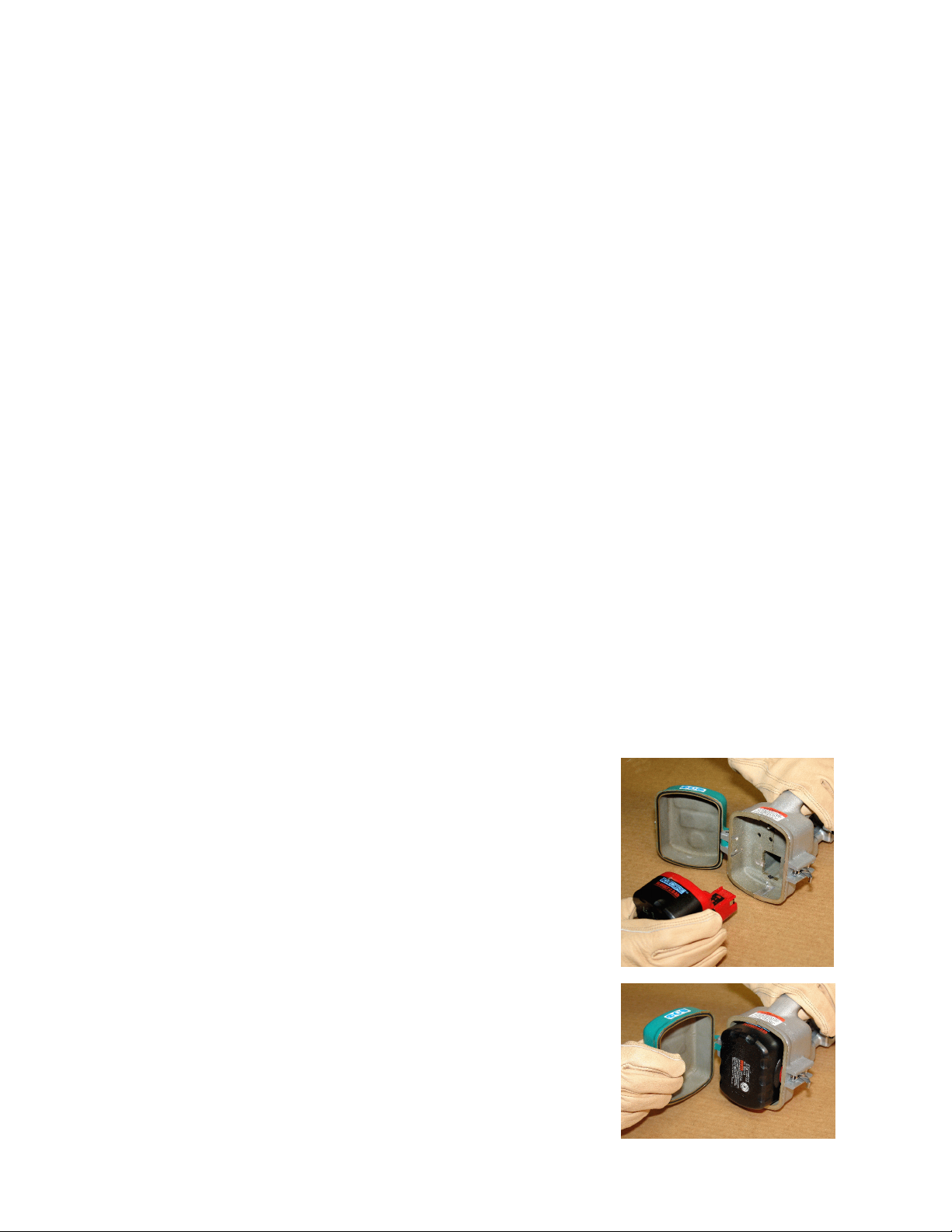
INSTALLING A BATTERY
1. Release the latch that secures the battery cover. Open the
battery cover.
2. Insert the battery into the BTS. Firmly push the battery in until
fully seated.
3. Close and latch the cover.
NOTE: Do not operate tool with battery cover open.
Occasionally inspect the battery compartment for moisture.
Inspect the battery cover gasket for wear, replace if needed.
6
Page 7
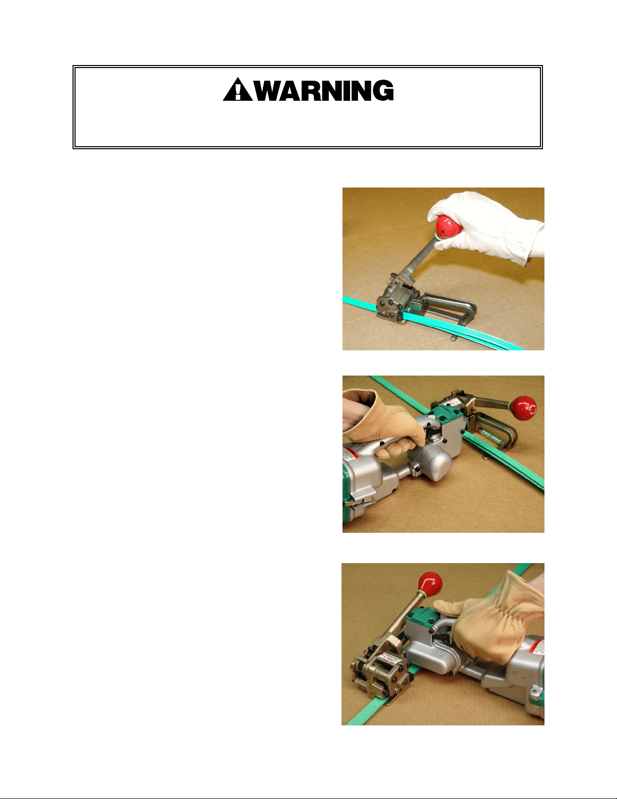
OPERATING INSTRUCTIONS
Wear safety glasses. Stand to one side of the strap when tensioning.
ke sure all bystanders are clear before proceeding.
Ma
PLEASE NOTE: Do not operate tool without strap, as damage to the tool may occur.
1. Using a Signode PT manual strap tensioner tool,
encircle the package with strap and tension the
strap as required.
Refer to the Signode PT tool’s operation, parts and
safety manual for proper use of the tool.
2. Squeeze the operator handle of the BTS to open
the upper welding gripper.
3. While holding the operator handle, align the BTS
with the tensioner as shown, slide the nose of the
BTS tool over the upper and lower straps.
7
Page 8
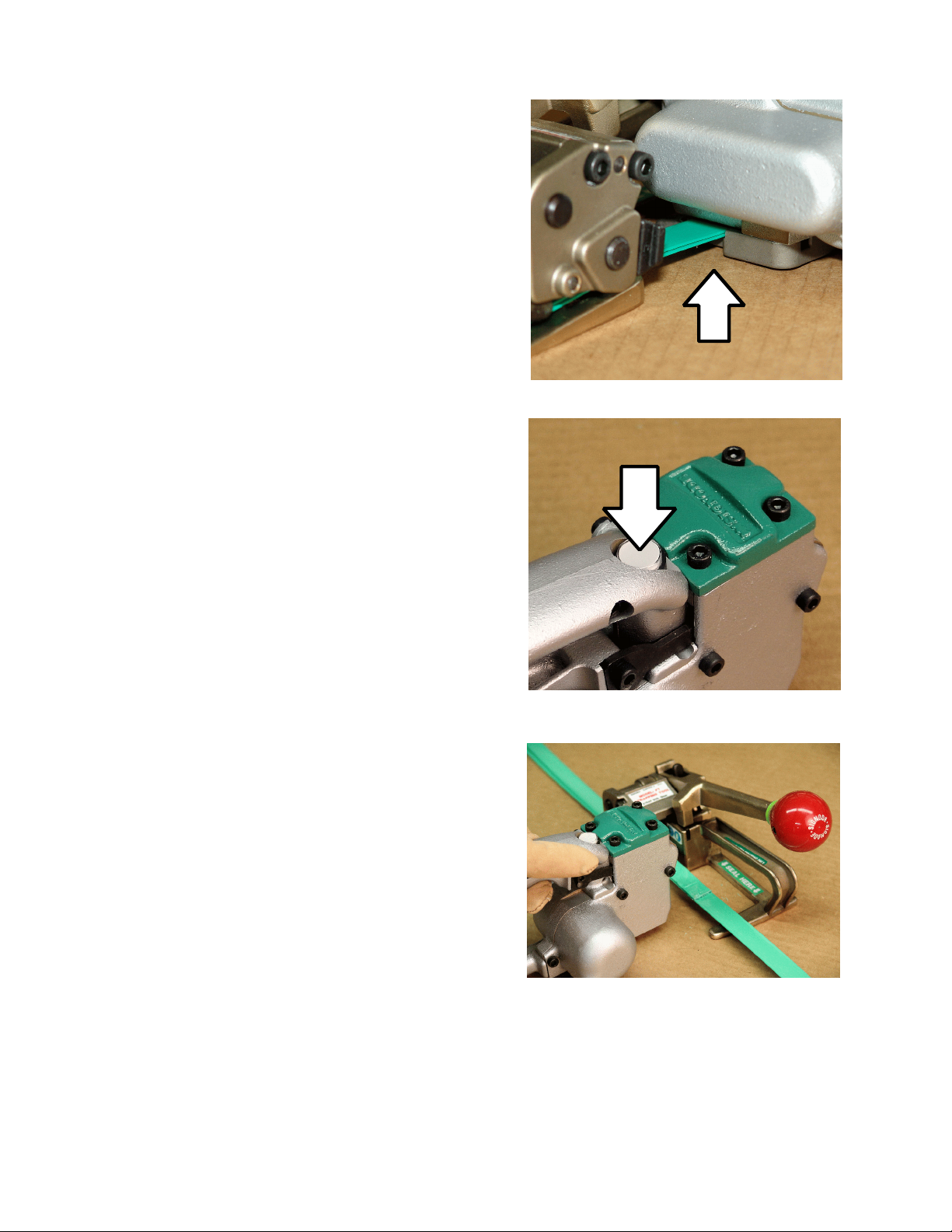
OPERATING INSTRUCTIONS, Continued
4
. Push the BTS tool all the forward so that the straps
are fully seated into the base of the tool as shown.
5. Release the operator handle to secure the strap in
the tool. Press the weld button on the top of the
tool.
The BTS will then weld the strap together. As the
straps are welded together the BTS will also cut off
the top strap.
While operating, the weld button will glow the
color Red. Once the welding process has been
completed the weld button will continue to glow
Red indicating the wait period before removing the
tool.
NOTE: If the weld button immediately flashes Red
and the tool does not function the battery cell
needs to be charged.
6. Once the weld button begins to flash Green in
color, squeeze the operator handle to open the
tool and remove the tool from the strap.
Continue to remove the strap tensioner from the
strap.
Inspect the strap joint for proper formation using
the information found on the next page of this
manual
8
Page 9
STRAP JOINT INSPECTION
T
his tool is a Tension Weld® type sealer. A properly made joint will appear as shown in the
illustration. If the joint does not appear as shown, then the operator must proceed as
follows:
1. Ensure that the tool operating instructions are being followed before applying another
strap.
2. Cut the strap off and apply another.
A good weld will show some material displacement along
the edges. The welded area should extend the full length
and width of the gripper impression.
If the joint still does not appear as shown, then inspect the tool for worn and/or damaged
parts. Replace tool parts as needed. NEVER HANDLE OR SHIP ANY LOAD WITH
IMPROPERLY FORMED JOINTS. Misformed joints may not secure the load and could cause
serious injury.
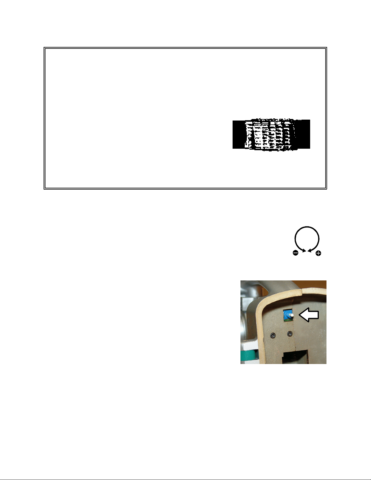
WELD TIME ADJUSTMENT
Weld time duration has been factory adjusted to provide acceptable weld strength
when using High Strength Tenax (polyester) type strap. Weld time may need to be
adjusted due to the application, environment, tool wear, etc. Adjustments are made
by turning the adjustment screw, located inside the battery compartment. Turn the
screw clockwise to increase weld time and counterclockwise to decrease weld time.
Establishing the correct weld time is a matter of trial and error and should be conducted as
follows.
1. Remove the tool battery to access the adjustment screw.
Adjust the screw in 1/8 to 1/4 turn increments only.
2. Reinstall the battery, apply a strap and make a weld.
3. Compare the weld made with the illustration shown above. A
good weld will displace some material along the outer edges
of the joint.
4. If you are unable to produce an acceptable joint or if you have
any questions as to whether your tool is producing good weld
strength, contact your Signode Sales Representative.
9
Page 10

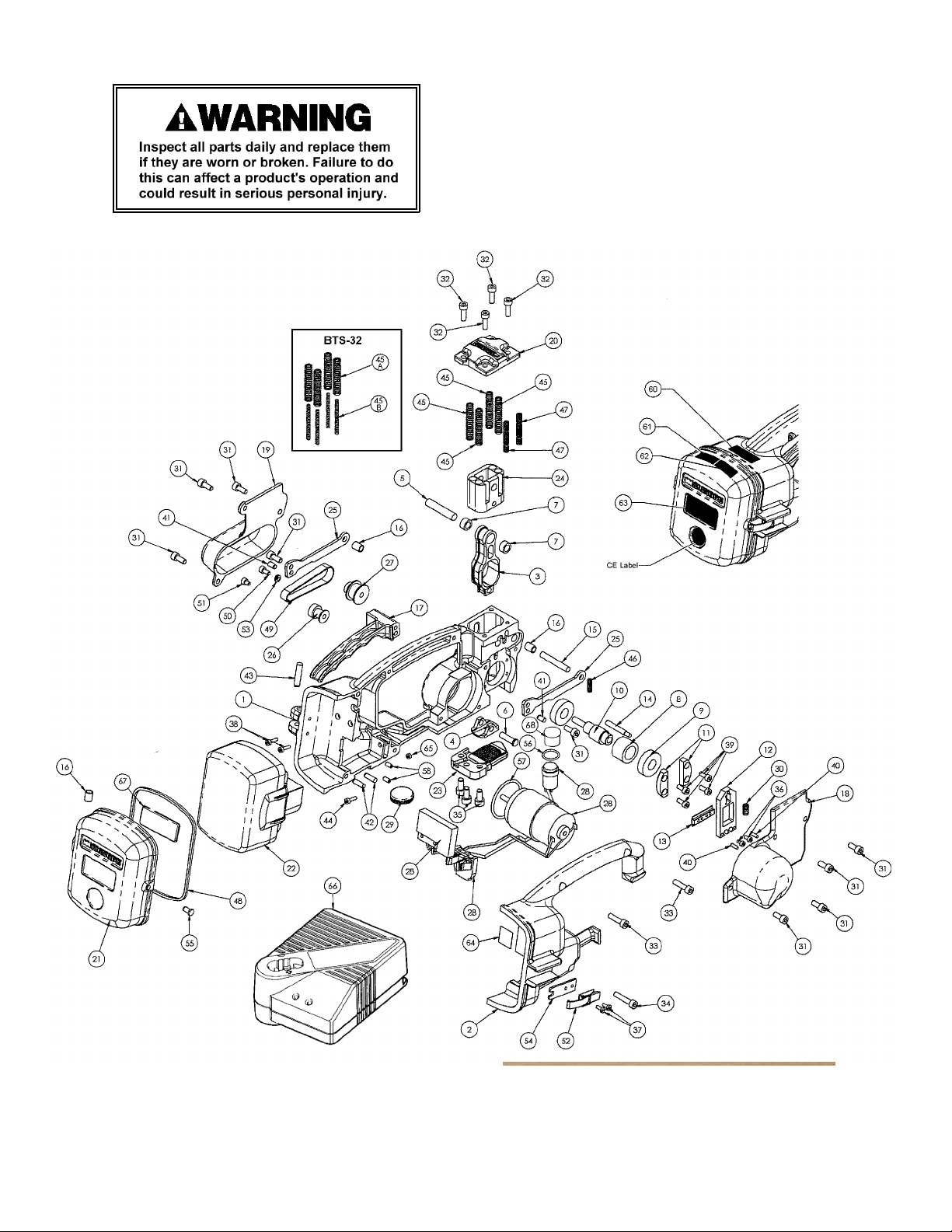
PARTS LIST
Qty Part No. Description
Key
1 1 426583 Frame (16/19/25)
1
427139 Frame (32)
2 1 426586 Frame Cover
3 1 426508 Vibrator Arm
4
1 426577 Weld Gripper (16/19/25)
1 427138 Weld Gripper (32)
5 1 427074 Piston Pin
6
1 426511 Pivot Pin (16/19/25)
1 427134 Pivot Pin (32)
7 2 423997 Bearing INA HK0808
8 1 423994 Bearing INA NK 16/16
9 2 423889 Bearing
10 1 426576 Eccentric Shaft 0.9mm
11 2 426901 Cutter Guide
12 1 426512 Cutter Insert Holder
13
1 426581 Cutter Insert (16/19/25)
1 427136 Cutter Insert (32)
14 1 426884 Cutter Pin
5 1 427075 Handle Pin
1
16 3 427076 Garlock 0610DU Bushing
17 1 426596 Handle
18 1 426588 Motor Cover
19 1 426592 Belt Cover
20 1 426590 Cover
21 1 426594 Battery Cover
22
1 427087 14.4 V Battery Cell
23 1 427079 Base (16mm)
1 426906 Base (19mm)
1 426907 Base (25mm)
1 427141 Base (32mm)
24 1 426575 Piston
5 2 426897 Lift Arm
2
26* 1 426578 Gates Pulley 16 Teeth
27* 1 426579 Gates Pulley 28 Teeth
28 1 427085 Electrical Assy
1 427089 PC Board
1 427084 Battery Connector
1 427077 Lighted Switch
1 427078 Mabuchi Motor
29 1 427081 Wear Pad
30 1 423943 Spring
31 9 423288 M5 X 12 SHCS
32 4 170304 M5 X 16 SHCS
33 2 166063 M5 X 20 SHCS
34 1 010031 M5 X 25 SHCS
35 3 280848 M6 X 12 SHCS
36 2 262456 M3 X 6 SHCS (16/19/25)
2 428492 M3 X 4 SHCS (32)
37 2 427104 M3 X 8 SPHMS
38 2 259935 M3 X 12 SHCS
39 4 420216 M4 X 10 SHCS
40 2 274451 3 X 10 Dowel Pin (16/19/25)
2 299975 3 X 8 Dowel Pin (32)
41 2 181261 5 X 10 Dowel Pin
42 2 423493 5 X 16 Dowel Pin
43 1 162404 6 X 28 Dowel Pin
44 1 428229 M4 x 14 SLHSS
45 4 427080 Lee Spring LC-047D-16M
45A 4 428264 Lee Spring LC-032BB-19M
45B 4 428265 Lee Spring LC-49D-17M
Qty Part No. Description
Key
46 1 427082 Lee Spring LC-020B-8M
4
7 2 427083 Lee Spring LC-035C-15M
48 1 427086 O-Ring SAE -157
1 426580 Gates Belt
49
50 2 162383 M4 X 8 SHCS
1 1 423591 M4 X 5 SHCS
5
1 426665 Draw Latch
52
53 1 427096 Nord-Lock M4
4 1 427099 Door Catch
5
55 1 427098 Button Keeper
56 1 022789 O-Ring SAE-16
57 1 427103 O-Ring SAE-130
60 1 003132 Warning Sign
61 1 024727 Information Sign
62 1 286383 Information Sign
63 1 436396 Nameplate (BTS-16)
1 436397 Nameplate (BTS-19)
1 436398 Nameplate (BTS-25)
1 510455 Nameplate (BTS-32)
64 1 510450 Information Sign
65 1 252230 M4 Hex Locknut
66 1 427091 Battery Charger (110V)
1 429510 Battery Charger (220V)
67 1 428224 Bumper
68 1 428138 Push Button Cover
! When ordering parts please indicate tool
model, part number and description.
! Recommended spare parts are underlined
and should be stocked.
! Common hardware parts can be obtained at
any local hardware supply.
* Includes mounting screws.
NOTE:
When installing the electrical assembly (Key 28),
fill the wire channel with hot-melt glue as
indicated below to secure the wire harness.
10
Page 11
11
Page 12
TROUBLE SHOOTING
T
he following items are the most common types of tool malfunctions. For symptoms or remedies
not shown, contact your Signode service representative for additional information and details.
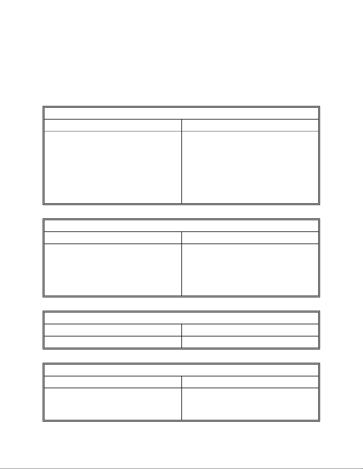
The following tool conditions are shown in this manual:
#1 - A poor weld identified by an incomplete area of weld.
#2 - Incomplete or no weld.
#3 - Strap is over welded.
#4 - The cut-off has become difficult.
#1 CONDITION: A poor weld identified by an incomplete area of weld.
CAUSE REMEDY
Welding is achieved by a combination of
vibration and downward pressure of the
upper gripper. Either a restriction of motion
or a reduction of downward pressure will
cause a poor weld.
#2 CONDITION: Incomplete or no weld.
CAUSE REMEDY
1. Improperly set weld time adjustment.
2. Worn teeth on upper or lower weld pads.
3. Low battery voltage.
Dismantle and clean the weld mechanism by
brushing away the strap residue or washing
the entire unit in a solvent. When a solvent
is used it is imperative the assembly be
blown dry to remove all solvent. Check for
dry or worn bearings. Replace or lubricate
as required. If the tool has been used
extensively, examine the teeth on the upper
and lower weld pads for wear. Replace if
worn.
1. Adjust weld time as required per
instruction in this manual.
2. Replace as required.
3. Recharge battery as required.
#3 CONDITION: Strap is over welded.
CAUSE REMEDY
Improper weld timing adjustment. Decrease weld timing as needed.
#4 CONDITION: The cut-off has become difficult.
CAUSE REMEDY
1. Strap residue jamming cutter mechanism.
2. Cutter blade worn or damaged
adjustability.
1. Clean parts as required.
2. Replace as required.
12
Page 13
TOOL MAINTENANCE
G
ENERAL
1. Clean the teeth on the upper welding gripper and welding base with the special brush
provided.
2. Periodically clean the tool with compressed air.
3. Disassemble, clean and lubricate the welding and cutting mechanisms.
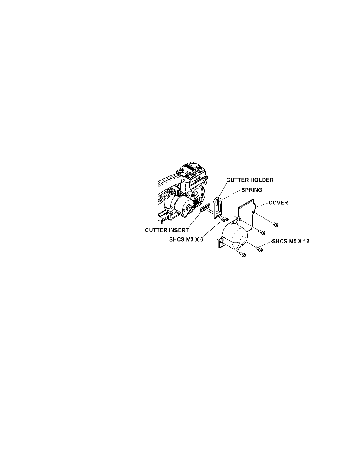
CUTTER INSERT SERVICE
The cutter insert of the BTS has two serrated cutting edges. Over time the cutter blade insert may
become worn. Use the instructions below to reverse the insert to use the other cutting edge. If
the blade has been previously reversed, it should be replaced with a new part. These instructions
can also be used for installing a new cutter insert.
! Remove the battery cell from
the tool.
! Remove the four M5x12 socket
head cap screws which secure
the front cover to the tool.
! Remove the cutter holder from
the tool. The small
compression spring should
remain with the cutter holder as
it is removed.
! Remove the two M3x6 socket
head cap screws which secure
the cutter insert. Rotate the
cutter insert 180B and reinstall
(or replace if new).
! Clean any debris from the tool and apply a light coating of grease to the cutter holder.
! Reinstall the cutter holder into the tool. Continue to reinstall the from cover.
13
Page 14

14
Page 15

EU Declaration of Conformity
T
he Supply of Machinery (safety) Regulations
19
92 (S.I. 1992/3073)
It is hereby declared that the undermentioned machinery has been designed and
constructed to comply with the health and safety requirements defined in EC Directive
89/392/EEC
Machine Supplier: Signode, Division of ITW Ltd.
Queensway, Fforestfach
Swansea SA5 4ED
Machine Description: BTS Series
Machine Type: Electric Combination Hand Strapping tool.
Provisions with which machine complies:
89/392/EEC, 91/368/EEC
Harmonized EuroNorms with which machine complies:
EN 292:1, EN 292:2, EN 294, EN 349
Technical Standards with which machine complies:
NA
Signature: Date: 12 July 2007
(Peter Oseland)
15
Page 16
SIGNODE
NEW TOOL WARRANTY
Signode Engineered Products Warrants that a new Signode strapping tool will operate per functional
specifications for a period of sixty (60) days after the date of shipment to the owner's place of business.
Normal wearing parts, as outlined in the Operation, Parts & Safety manual, are covered by a thirty (30)
day warranty unless, in Signode's judgment, these parts have been subjected to abnormal or extreme
usage. Signode's sole liability hereunder will be to repair or replace, without charge, F.O.B. Signode's
Glenview, Illinois plant, any tool which proves to not operate per functional specifications within the
stated period. Signode reserves the right to replace any tool which proves not to operate per functional
specifications with a new or like-new tool of the same model if in Signode's judgment such replacement
is appropriate. Any new replacement tool provided to an owner will carry a full sixty (60) day warranty.
Any warranty repaired tool or like-new replacement tool will carry a warranty for the balance of the time
remaining on the initial sixty (60) day warranty. This warranty will be extended to compensate for the
time the tool is in Signode's possession for warranty repairs.
This warranty is void as to any tool which has been: (I) subjected to mis-use, misapplication, accident,
damage, or repaired with other than genuine Signode replacement parts, (II) improperly maintained, or
adjusted, or damaged in transit or handling; (III) used with improperly filtered, unlubricated air or
improper strapping material, (IV) in Signode's opinion, altered or repaired in a way that affects or
detracts from the performance of the tool.
SIGNODE MAKES NO WARRANTY, EXPRESSED OR IMPLIED, RELATING TO MERCHANTABILITY,
FITNESS OR OTHERWISE EXCEPT AS STATED ABOVE AND SIGNODE'S LIABILITY AS ASSUMED ABOVE
IS IN LIEU OF ALL OTHERS ARISING OUT OF OR IN CONNECTION WITH THE USE AND PERFORMANCE
OF THE TOOL. IT IS EXPRESSLY UNDERSTOOD THAT SIGNODE SHALL IN NO EVENT BE LIABLE FOR
ANY INDIRECT OR CONSEQUENTIAL DAMAGES INCLUDING, BUT NOT LIMITED TO, DAMAGES WHICH
MAY ARISE FROM LOSS OF ANTICIPATED PROFITS OR PRODUCTION, SPOILAGE OF MATERIALS,
INCREASED COSTS OF OPERATION OR OTHERWISE.
Considerable effort has be made to ensure that this product conforms to our high quality standards.
owever, should you experience any difficulties, please contact your Sales Representative providing
H
samples and the manufacturing code specified on the tool.
Thank you for your help.
SIGNODE ENGINEERED PRODUCTS
Hand Tool Division
3620 W. Lake Avenue, Glenview, Illinois 60025
© Copyright 2011, Signode 512183 12/2011
 Loading...