

Page 1
SCM-12/58/34
MANUAL COMBINATION STRAPPING TOOL
Page 2
2
READ THESE INSTRUCTIONS CAREFULLY.
FAILURE TO FOLLOW THESE INSTRUCTIONS CAN RESULT IN SEVERE PERSONAL INJURY.
GENERAL SAFETY CONSIDERATIONS
1.
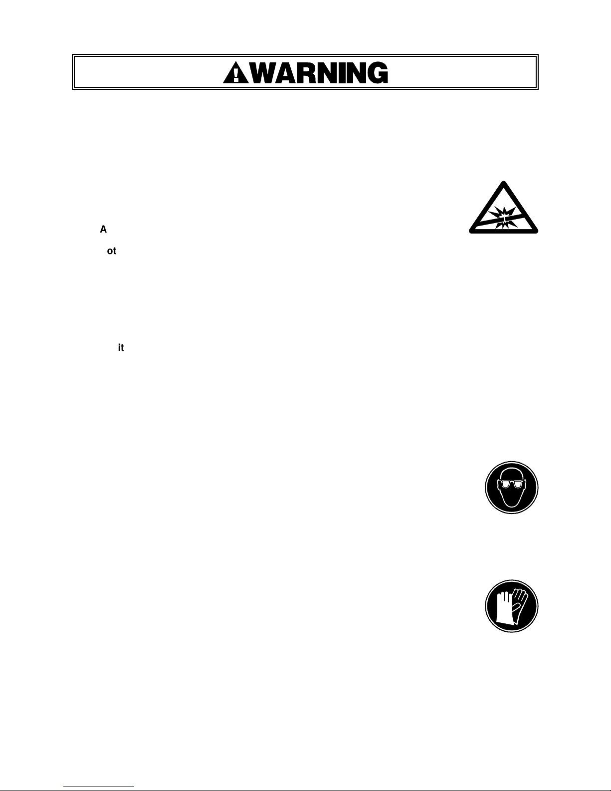
STRAP BREAKAGE HAZARD.
Improper operation of the tool or sharp corners on the load can result in
strap breakage during tensioning, which could result in the following:
A sudden loss of balance causing you to fall.
Both tool and strap flying violently towards your face.
Failure to place the strap properly around the load or an unstable or shifted load could result
in a sudden loss of strap tension during tensioning. This could result in a sudden loss of
balance causing you to fall.
Read the tool's operating instructions. If the load corners are sharp use edge protectors.
Place the strap correctly around a properly positioned load.
Positioning yourself in-line with the strap, during tensioning and sealing, can result in
severe personal injury from flying strap or tool. When tensioning or sealing, position
yourself to one side of the strap and keep all bystanders away.
2.
TRAINING.
This tool must not be used by persons not properly trained in its use. Be certain that you
receive proper training from your employer. If you have any questions contact your Signode
Representative.
3.
EYE INJURY HAZARD.
Failure to wear safety glasses with side shields can result in severe eye injury
or blindness. Always wear safety glasses with side shields which conform to
ANSI Standard Z87.1 or EN 166.
4.
FALL HAZARD.
Maintaining improper footing and/or balance when operating the tool can cause you to fall. Do
not use the tool when you are in an awkward position.
5.
CUT HAZARD.
Handling strap or sharp parts could result in cut hands or fingers. Wear protective
gloves.
6.
TOOL CARE.
Take good care of the tool. Inspect and clean it daily, lubricate it weekly and adjust
when necessary. Replace any worn or broken parts.
7.
WORK AREA.
Keep work areas uncluttered and well lighted.
Page 3
3
8.
OPERATING SEQUENCE.
Use the correct Signode products for your application. If you need help contact your Signode
Representative. Before using this sealless tool, read the Operation and Safety Instructions
contained in this manual.
9.
JOINT FORMATION
Sealless joints are formed when overlapping straps are punched simultaneously creating
interlocking keys. However, the integrity of the joint is obtained when the keys punched in the
upper strap move in relation to the keys on the bottom strap, allowing the straps to interlock.
The movement necessary to create the interlock comes from the strap tension release where
the top strap moves one direction and the bottom strap moves in the other direction.
Therefore, never attempt to make a sealless joint without having the straps under tension.
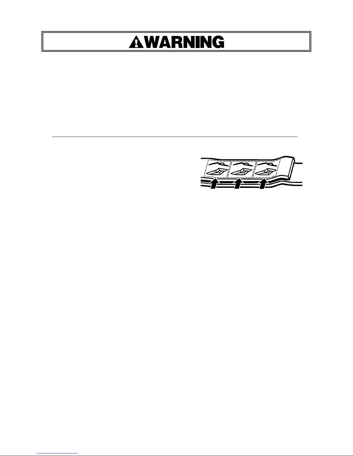
This tool is a punch type sealer. A properly formed joint will appear as shown in the
illustration. If the joint does not appear as shown,
then the operator must proceed as follows:
A.
Ensure that the tool's operating instructions are
being followed before applying another strap.
B.
Ensure that tension has been applied to the
straps before the sealer handle is activated.
Tension is necessary to ensure that the keys fully interlock.
C.
After confirming the above cut the strap off and apply another.
If the joint still does not appear as shown, then inspect the tool for worn and/or damaged
parts. Replace tool parts as needed. NEVER HANDLE OR SHIP ANY LOAD WITH
IMPROPERLY FORMED JOINTS. Misformed joints may not secure the load and could cause
serious injury.
Always tuck the strap end back into the dispenser when not in use.
10.
CUTTING TENSIONED STRAP
Using claw hammers, crowbars, chisels, axes or similar tools can cause tensioned strap to fly
apart with hazardous force. Use only Signode cutters designed for cutting strap such as the
Model CU-30. Read the instructions in the cutter's manual for proper procedure in cutting
strap. Before using any Signode product read its Operation and Safety Manual.
Page 4
4
Signode
tools
and machines
are designed
and warranted
to
work
toget
her
with
Signode strapping and seals. Use of non-
Signode
strap,
seals
and/or
manufactured
or specified
repla
c
ement
parts
may result
in strap
breakage
or
joint
separation
while
applying
strapping
to a
load
or
during
normal shipping
and handling. This could
result in severe personal injury.
TABLE OF CONTENTS
Page
General Safety Instructions
2
Introduction
4
Specifications
5
Major Components
5
Operating Instructions
6
Strap Joint Formation & Appearance
8
Adjustments
9
Parts List
10
Troubleshooting
13
Changing Strap Sizes
16
Tool Options
18
Declaration Of Conformity
19
INTRODUCTION
The SCM is a light weight, manually operated hand tool intended for use with Apex and Magnus
strapping. The tool is easy to load, tension and seal.
Once the strap has been placed around the package, the operator puts both layers of strap into
the tool, lowers the feed wheel, removes any strap slack and tensions the strap. The keyed
sealless joint is then created and the strap is cut free of the supply.
This manual provides the information necessary for the operation of the SCM hand tool and lists
all of the parts in the event maintenance is needed. Therefore, it is valuable and should be saved.
Extra care should be taken in performing maintenance on the SCM since fasteners and other small
components used on this tool are a combination of SAE and metric sizes.
Page 5
5
SPECIFICATIONS
TOOL MODEL
STRAP
TYPE
WIDTH
THICKNESS
SCM-12
P/N 424350
Apex
&
Magnus
1/2" (12.7mm)
0.015 - 0.025"
(0.38 - 0.64mm)
SCM-58
P/N 424358
5/8" (15.9mm)
SCM-34
P/N 424334
3/4" (19.1mm)
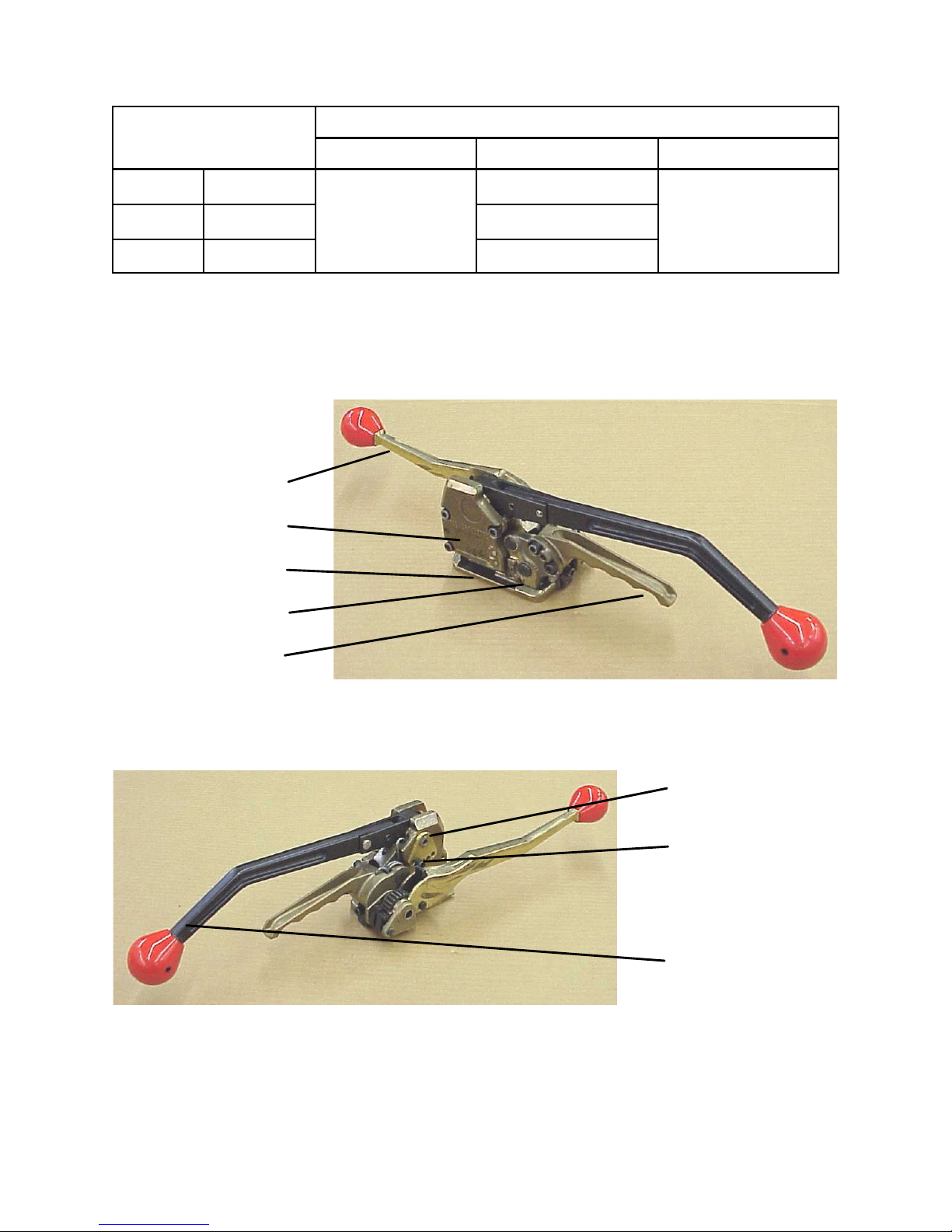
MAJOR COMPONENTS
TENSION HANDLE
SEALER COVER
BASE
FEEDWHEEL COVER
FEEDWHEEL
SUPPORT HANDLE
CUTTER ADJUSTMENT
TENSION RELEASE
SEALER HANDLE
Page 6
6
OPERATING INSTRUCTIONS
Wear safety glasses. Stand to one side of the strap while tensioning.
Make sure all bystanders are clear before proceeding.
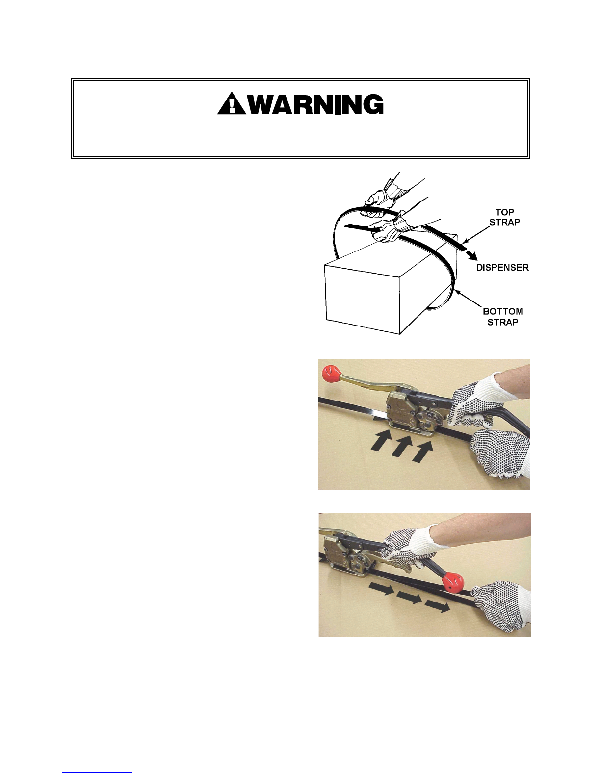
1.
STRAP PREPARATION.
Encircle the package with strap by passing the
loose end over the top and bringing it back
around. This will result in a top strap and a
bottom strap.
2.
TOP AND BOTTOM STRAP INSERTION. Squeeze
the sealer handle and the feedwheel support
handle together with the right hand. With the left
hand, align the top and bottom straps. Then,
with a sideways motion, insert them into the tool,
making sure both straps are fully seated in and
against the front and back strap guides. Note
that both straps must be placed between the
feed wheel and the clutch plug. Make sure the
lead end of the bottom strap extends about 1" to
1 1/2" (25 - 40mm) beyond the front of the tool.
3.
REMOVING SLACK STRAP. After the straps
have been inserted into the tool, release the
feedwheel support handle. With the left hand,
grasp the top strap and pull back on it to
remove slack strap. Pull it snug around the
package. The feed wheel will rotate as the strap
is being pulled back.
Page 7
7
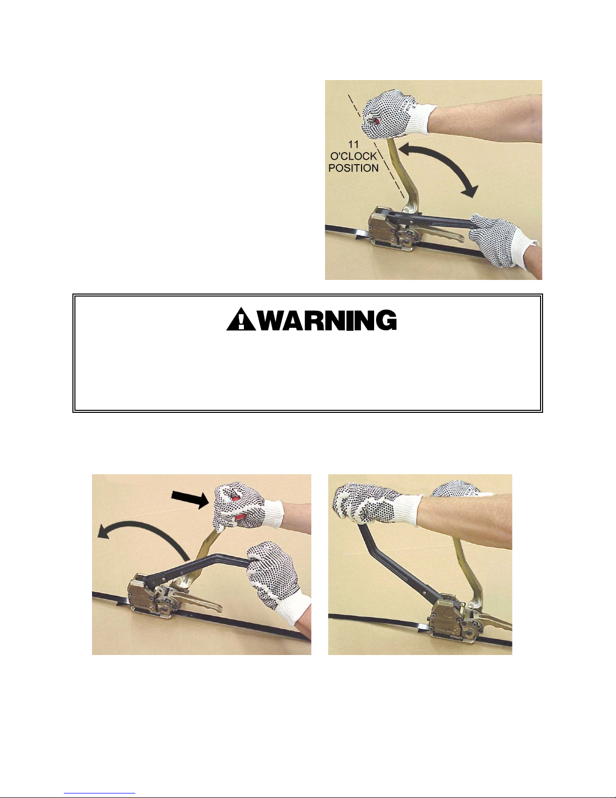
4.
APPLYING TENSION. While standing to one side
of the strap line, grasp the tension handle with
the right hand and the sealer handle with the left
hand. Move the tension handle forward and
back between the 11 o'clock and 2 o'clock
positions repeatedly, until the strap is tensioned
around the package.
Never push the tension handle all the way forward past the 11 o'clock position as the
feedwheel will lift and the tensioned strap will release from the tool.
Never squeeze the feedwheel support handle and sealer handle together while
tensioning strap.
5.
SEALING THE STRAPS. After the strap has been tensioned, grasp the sealer handle with the
left hand. Move the sealer handle fully forward while pulling back on the tension handle to
punch completely through both layers of strap.
NOTE: If the sealer handle is not cycled fully forward the strap will not be completely punched
or cut off. If this occurs the tool cannot be removed from the tensioned strap. To remove the
tool cycle the sealer handle completely forward a second time. If the tool still fails to
completely cut or punch the straps, cut the straps and tool from the package. Check the tool
for worn or broken parts. Inspect the strap joint for proper formation of interlocking keys.
Page 8
8
OPERATING INSTRUCTIONS, Continued
6.
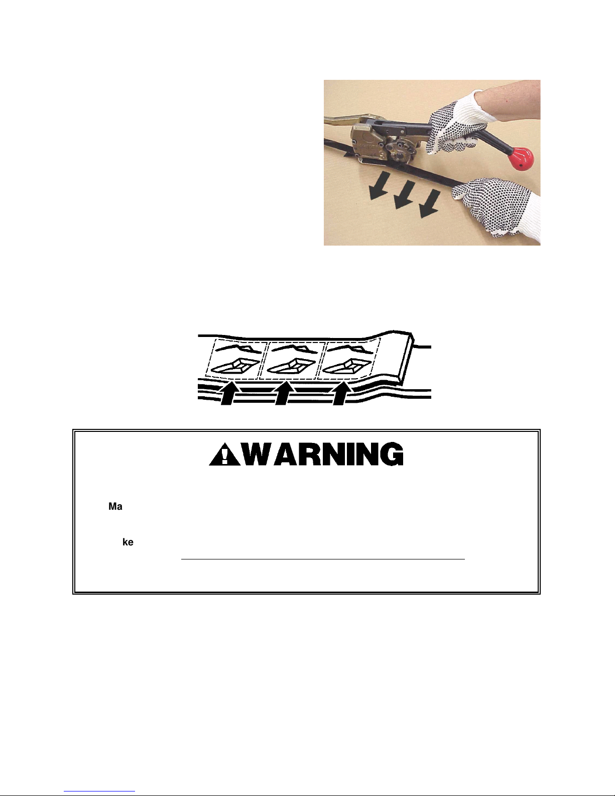
REMOVING THE TOOL. Hold the cut-off end of
the top strap with the left hand and squeeze the
feedwheel support handle and the sealer handle
together with the right hand. Swing the rear end
of the tool to the right to remove it from the
tensioned tie. The strapping cycle is now
complete. Inspect the strap joint for proper
formation by reviewing Joint Appearance and
Formation below.
STRAP JOINT APPEARANCE & FORMATION
A properly formed joint will appear as shown in the following illustration.
If the joint does not appear as shown, then the operator must proceed as follows:
Make sure that the tool's operating instructions are being followed
before applying
another strap.
Make sure that tension has been applied to the straps before the sealer handle has
been actuated.
Tension is necessary to ensure that the keys fully interlock.
After confirming the above, cut off the strap and apply another.
If the joint still does not appear as shown, then inspect the tool for worn and/or damaged parts.
Replace tool parts as needed.
NEVER HANDLE OR SHIP ANY LOAD WITH IMPROPERLY FORMED JOINTS.
Misformed joints may not secure the load and could cause serious injury.
Page 9
9
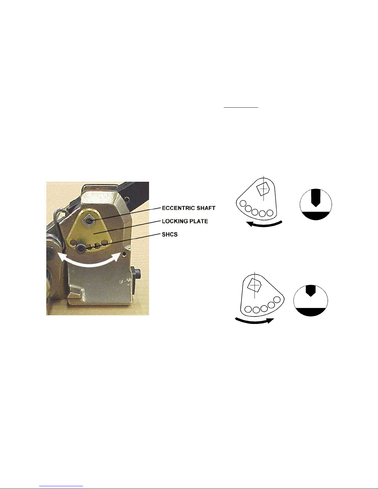
ROTATE THE LOCKING PLATE
CLOCKWISE TO LOWER THE CUTTER
FOR THINNER GAUGE STRAPPING.
ROTATE THE LOCKING PLATE
COUNTERCLOCKWISE TO RAISE THE
CUTTER FOR HEAVIER GAUGE
STRAPPING.
ADJUSTMENTS
CUTTER
The cutter may have to be adjusted if the tool has been altered to accept a different width or
thickness of strap or an adjustment may be needed if the cutter has been replaced due to wear or
damage.
Run a cycle with strap of the size to be used. A properly adjusted cutter will sever the top strap
completely but the lower strap will have minimal impression,
at the most.
Excessive scoring of
the lower strap is an indication of over cutting and this is not acceptable.
Lay the tool with the strap loading side down, remove the socket head cap screw (SHCS) that
attaches the locking plate to the base (it is not necessary to remove the locking plate). Insert a 5.0
mm hex wrench into the end of the eccentric shaft. Rotate the shaft clockwise a few degrees for
thinner strap or counterclockwise for heavier strap. There are two mounting holes available for
the locking plate. Align the “nearest” hole in the plate to the mounting hole in the base and
reinstall the socket head cap screw.
FEEDWHEEL AND CLUTCH PLUG
There is no adjustment for feedwheel/clutch plug clearance. The clearance should be .001" to
.010" (0.025 to 0.25mm). The most important issue is that the feedwheel does not interfere with
the clutch plug.
Page 10
13
TROUBLESHOOTING
The following items are the most common tool symptoms if problems should occur. For
symptoms or remedies not shown, contact your Signode service representative for additional
information and details. The following tool symptoms are shown in this manual:
#1 SYMPTOM: Difficult strap slack removal.
#2 SYMPTOM: Poor tensioning
#3 SYMPTOM: Joint fails after tool is removed or joint not made properly.
#4 SYMPTOM: Excessive effort needed to seal straps together.
#5 SYMPTOM: Tool will cut-off strap after sealing , or bottom strap cut too deep.
#6 SYMPTOM: Tool cannot be removed from strap after cycle is completed.
#7 SYMPTOM: Feedwheel slips during tensioning.
#1 SYMPTOM: Difficult strap slack removal.
CAUSE
REMEDY
1.
Strap not lubricated or not waxed
adequately.
2.
Strap not inserted properly (strap
caught by outer guide)
3.
Damaged parts in tension sub-
assembly.
1.
Purchase only lubicated (waxed)
strapping.
2.
Insert and align straps in tool properly.
3.
Inspect the tension assembly’s ratchet
wheel and pawls for damage or broken
parts.
#2 SYMPTOM: Poor tensioning.
CAUSE
REMEDY
1.
Feedwheel or clutch plug packed with
dirt or grit.
2.
Feedwheel or clutch plug teeth are
worn.
3.
Strap not properly aligned when
inserted into tool.
1.
If top strap is slipping, clean dirt from
the feedwheel or replace worn
feedwheel if necessary.
2.
If bottom strap is slipping, clean dirt
from the clutch plug or replace worn
clutch plug if necessary.
3.
Insert strap into tool carefully aligning
strap.
NOTE: Carefully inspect strap applied to determine if top or bottom strap is slipping.
Page 11
14
TROUBLESHOOTING, Continued
#3 SYMPTOM: Joint fails after tool is removed or joint does not appear to have been made
properly.
CAUSE
REMEDY
1.
Low joint strength caused by chipped or
worn sealer parts.
2.
Strap not strong enough to contain load
or force exerted by load.
3.
Joint made on strap that had not been
tensioned to a proper level.
4.
Strap not inserted properly- 3 punches
must penetrate both straps.
5.
Bottom strap being cut by the cutter.
1.
Inspect sealing parts for wear or
chipped edges.
2.
Review application to determine proper
strapping to use. If necessary contact
your Signode sales representative.
3.
Make sure that tension is applied to the
straps before the sealer handle is
operated.
4.
Insert straps with bottom strap
extending 1" to 1 1/2" (25-40mm) past
the front of the tool.
5.
Adjust cutter as required.
#4 SYMPTOM: Excessive effort needed to seal straps together.
CAUSE
REMEDY
1.
Broken needles within the sealer handle
assembly.
2.
Worn dies, punch or cutter.
3.
Poor tool lubrication.
1.
Carefully inspect sealer drive for worn or
broken parts.
2.
Replace appropriate dies, punch or
cutter.
3.
Lubricate eccentric shaft, bearing
needles, sealer cam and cam roller.
#5 SYMPTOM: Tool will not cut-off strap after sealing (cannot remove tool) or bottom strap cut
too deeply.
CAUSE
REMEDY
1.
Cutter blade damaged or worn. Cut
strap manually from package too
release tension and de-energize
feedwheel.
2.
Different gauge (thinner) strap requires
cutter adjustment.
1.
Inspect cutter for wear or damage, replace
as necessary.
2.
Adjust cutter blade for gauge of strap
being used.
Page 12
15
#6 SYMPTOM: Tool cannot be removed from strap after cycle is completed.
CAUSE
REMEDY
1.
Upper strap was not cut off.
2.
Chipped or worn parts (punches and
dies).
1.
Inspect both the cutter for damage or
adjustment. Cut strap manually from
package to release tension and de-
energize feedwheel.
2.
Inspect and replace worn sealer parts.
#7 SYMPTOM: Feedwheel slips during tensioning.
CAUSE
REMEDY
Flat spot on feedwheel.
Replace feedwheel.
Page 13
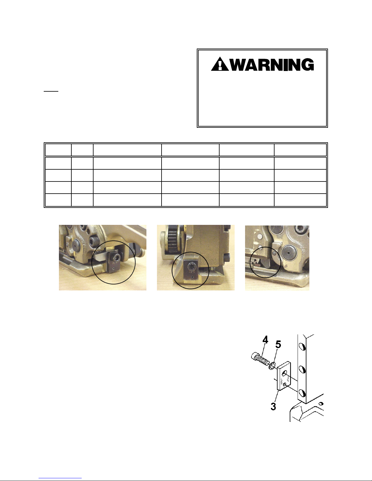
16
BACK GUIDE
FRONT GUIDE
OUTER GUIDE
CHANGING SCM STRAP SIZE
The following table illustrates the unique
parts to a particular strap size for the SCM
tool. If the strap size of the tool is to be
changed, this table must be used to
coordinate all the respective parts which
must
be reconfigured or replaced.
Follow all specified parts removal,
replacement & adjustment procedures found
in this manual when changing any of the
strap conversion parts.
Do not attempt to convert a tool’s strap
size without replacing/reconfiguring all
of the specified parts for the conversion.
Failure to replace/reconfigure all
required parts may cause severe
personal injury.
UNIQUE PARTS & CONFIGURATION TO SCM STRAP SIZES
KEY
QTY
DESCRIPTION
1/2" (12mm)
5/8" (16mm)
3/4" (19mm)
31Front Guide
424244, Note-1
424244, Note-2
424244, Note-2
21Back Guide
424245, Note-3
424245, Note-4
424245, Note-4
261Outer Guide
424121, Note-5
424121, Note-5
424121, Note-6
631Nameplate
424312
424314
424316
NOTES:
1.
Install guide (Key 3) with text “1/2" facing outward from tool.
Page 14
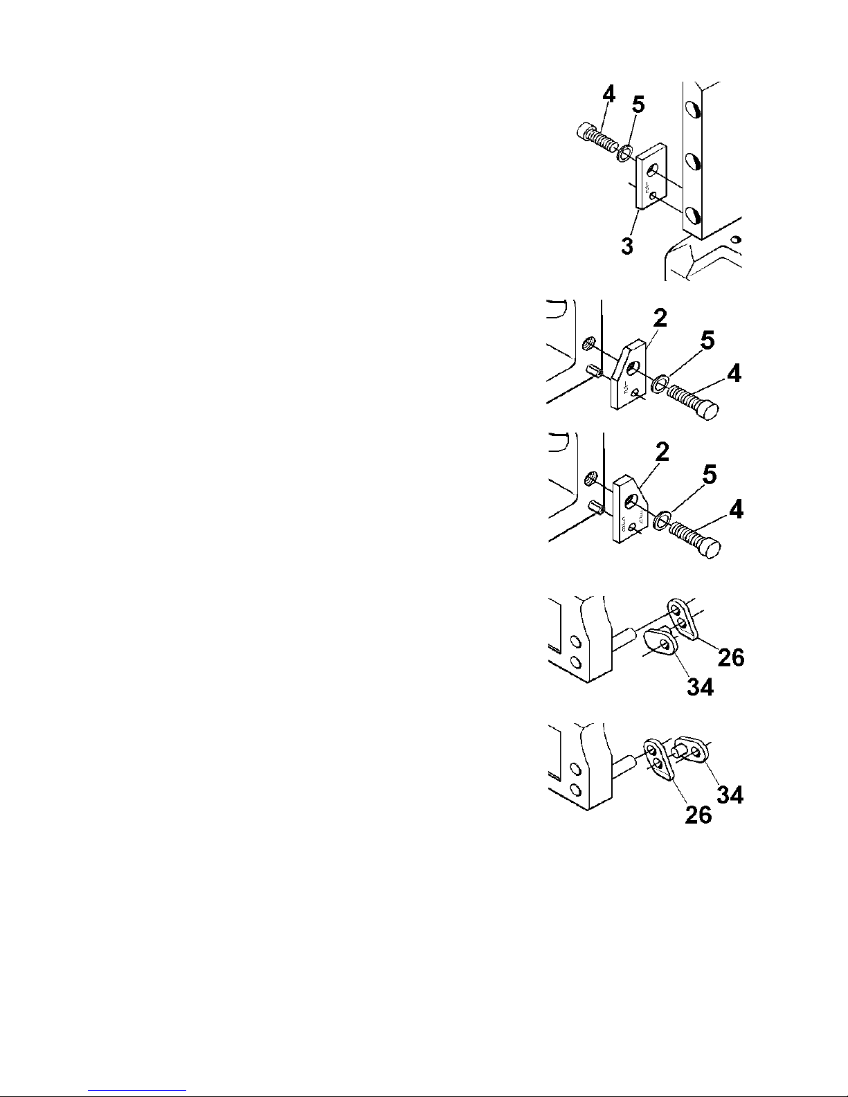
17
2.
Install guide (Key 3) with text “5/8 3/4" facing outward from tool.
3.
Install guide (Key 2) with text “1/2" facing outward from tool.
4.
Install guide (Key 2) with text “5/8 3/4" facing outward from
tool.
5.
Install the guide (Key 26) in the inward position. Install the link
(Key 34) in the outer position with the stem facing inwards.
NOTE: Always install guide (Key 26) with the
chamfer facing out.
6.
Install the guide (Key 26) in the outer position. Install the link
(Key 34) in the inner position with the stem facing outwards.
NOTE: Always install guide (Key 26) with the
chamfer facing out.
Page 15
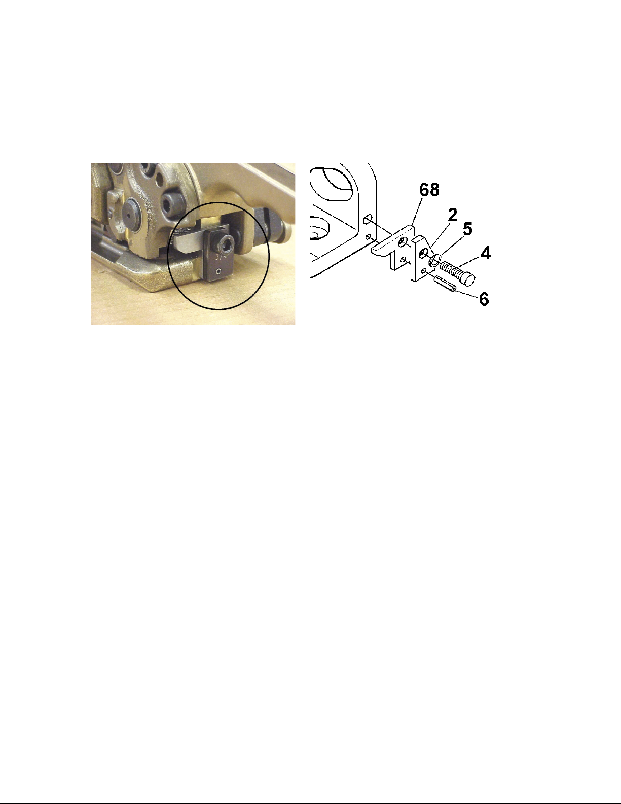
18
THE STRAP DEFLECTOR IS INSTALLED BEHIND
THE BACK GUIDE.
INSTALL THE DEFLECTOR USING THE EXISTING
MOUNTING HARDWARE.
TOOL OPTIONS
STRAP DEFLECTOR (Part No. 424321)
The strap deflector (Key 68) is an optional part which is used to prevent the strap from curling
around the feedwheel from severe high tension applications. The deflector is installed on the tool
behind the back guide (Key 2) as shown using the existing hardware.
Page 16

19
EU Declaration of Conformity
The Supply of Machinery (safety) Regulations
1992 (S.I. 1992/3073)
It is hereby declared that the undermentioned machinery has been designed and
constructed to comply with the health and safety requirements defined in EC
Directive 89/392/EEC
Machine Supplier:
Signode, Division of ITW Ltd.
Queensway, Fforestfach
Swansea SA5 4ED
Machine Description:
SCM
Machine Type:
Manual Combination Hand Strapping tool.
Provisions with which machine complies:
89/393/EEC, 91/368/EEC,
92/c 252/03, SI 1992/3703
Harmonized EuroNorms with which machine complies:
EN 292:1, EN 292:2, EN 294,
Pr EN 614, Pr EN 979, Pr EN 1005
Technical Standards with which machine complies:
NA
Signature:
Date:
1 AUG 2001
(Peter Oseland)
Page 17
© Copyright 2006, Signode 439960 Rev. 7/2006
SIGNODE
NEW TOOL WARRANTY
Signod
e Engineered Products Warrants that a new Signode strapping tool will operate per functional
specifications
for a period
of
sixty
(60) days
after the dat
e of shipment to the owner's place of business.
Normal
wearing
parts,
as
outlined
in
the Op
eration, Parts & Safety manual, are covered by a thirty (30) day
warranty
unless,
in
Signode's
judgement,
these
parts
hav
e been subjected to abnormal or extreme usage.
Signode's
sole liability hereunder will be to repair or replace, without charge, F.O.B. Signode's Glenview,
Illinois
plant,
any tool which
proves
to
not operate
per functional
specifications
within
the stated period.
Signode
reserves
the right
to
replace
any tool which
proves
not to operate
per functional
specifications
witha
new or like-new
tool of the same
model
if in
Signode's
judgement
such
replacement
is
appropriate.
Any new
replacement tool provided
to an
owner
will carry
a
full sixty
(60) day warranty.
Any warranty repaired tool or
like-new replacement tool
will carry
a
warranty
for the balance
of
the time remaining on the initial sixty (60)
day warranty.
This warranty
will be extended
to
compensate
for the time the tool is in Signode's
possession
for warranty repairs.
This war
ranty is void as to any tool which has been: (I) subjected to mis-use, misapplication, accident,
damage,
or
repaired
with other
than genuin
e Signode replacement parts, (II) improperly maintained, or
adjusted,
or
damaged
in
transit
or
handling;
(III) used
with improperly
filtered,
unlubricated
air
or improper
strapping
material,
(IV) in Signode's
opinion,
altered
or
repaired
in a
way that affects
or detracts from the
performance of the tool.
SIGNODE
MAKES
NO
WARRANTY,
EXPRESSED
OR
IMPLIED,
RELATING TO
MERCHANTABILITY,
FITNESS
OR OTHERWISE
EXCEPT
AS
STATED
ABOVE AND SIGNODE'S LIABILITY AS ASSUMED ABOVE IS IN LIEU
OF ALL OTHERS
ARISING
OUT OF OR IN CONNECTION
WITH
THE USE AND PERFORMANCE
OF
THE TOOL.
IT IS EXPRESSLY UNDERSTOOD THAT SIGNODE SHALL IN NO
EVENT
BE
LIABLE FOR ANY INDIRECT OR
CONSEQUENTIAL
DAMAGES
INCLUDING,
BUT NOT LIMITED
TO, DAMAGES
WHICH
MAY ARISE
FROM
LOSS
OF ANTICIPATED
PROFITS
OR
PROD
UCTION, SPOILAGE OF MATERIALS, INCREASED COSTS OF
OPERATION OR OTHERWISE.
Considerable
effort
has be made
to
ensure
that this product
conforms
to
our high quality
standards.
However,
should
you experience
any difficulties,
please
contact
your Sales
Representative
providing
samples
and the
manufacturing code specified on the tool.
Thank you for your help.
SIGNODE ENGINEERED PRODUCTS
Hand Tool Division
3620 W. Lake Avenue, Glenview, Illinois 60025
 Loading...