

Page 1
PRHM-34
PUSH TYPE POWER COMBINATION
STRAPPING TOOL
Page 2
READ THESE INSTRUCTIONS CAREFULLY. FAILURE TO FOLLOW THESE INSTRUCTIONS CAN
RESULT IN SERIOUS PERSONAL INJURY.
STRAP BREAKAGE HAZARD
Improper operation of the tool or sharp corners on the load can result in strap breakage during
tensioning, which could result in the following:
! A sudden loss of balance causing you to fall.
! Both tool and strap flying violently towards your face.
Failure to place the strap properly around the load or an unstable or shifted load could result in a
sudden loss os strap tension during tensioning. This could result in a sudden loss of balance
causing you to fall.
! If the load corners are sharp use edge protectors.
! Positioning yourself in-line with the strap, during tensioning and sealing, can result in
serious personal injury from flying strap or tool. When tensioning or sealing, position
yourself to one side of the strap and keep all bystanders away.
TRAINING
This tool must not be used by persons not properly trained in its use. Be certain that you receive
proper training from your employer. If you have any questions contact your Signode
Representative.
EYE INJURY HAZARD
Failure to wear safety glasses with side shields can result in serious eye injury or
blindness. Always wear safety glasses with side shields which conform to American
National Safety Institute standard Z87.1 or Euro Norm 166.
FALL HAZARD
Maintaining improper footing and/or balance when operating the tool can cause you to fall. Do
not use the tool when you are in an awkward position.
CUT HAZARD
Handling strap or sharp parts could result in cut hands or fingers. Wear protective
gloves.
TOOL CARE
! Inspect and clean the tool daily. Replace all worn or broken parts.
! Lubricate all moving parts weekly unless otherwise specified.
! On air powered tools, always disconnect the pneumatic connection to the tool when
performing part removal and replacement procedures. NEVER connect a pneumatic source to
a disassembled tool unless otherwise specified.
WORK AREAS
Keep work areas uncluttered and well lighted.
2
Page 3
READ THESE INSTRUCTIONS CAREFULLY. FAILURE TO FOLLOW THESE INSTRUCTIONS CAN
RESULT IN SERIOUS PERSONAL INJURY.
! Use correct Signode products for your application. If you need help contact your Signode
Representative.
! Signode tools and machines are designed and warranted to work together with Signode
strapping and seals. Use of non-Signode strap and seals and/or manufactured or
specified replacement parts may result in strap breakage or joint separation while
applying strapping to a load or during normal shipping and handling. This could result in
serious personal injury.
JOINT FORMATION
! Before using this tool, read its Operation and Safety instructions
contained in this manual.
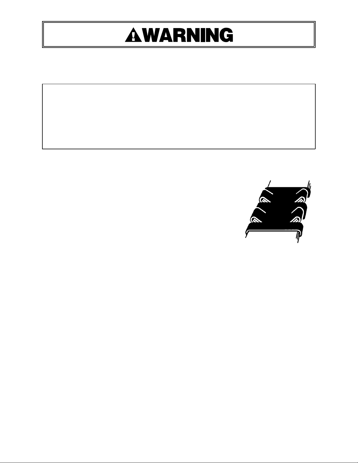
! This tool is a double reverse notch-joint sealers. Each notch-joint
must be inspected to make certain it has four (4) good notches. A
properly formed notch-joint will appear as shown in the
illustration. If the notch-joint does not appear as shown, then the
operator must proceed as follows.
1. Make certain that the tool's operating instructions are being
followed before applying another strap.
2. Cut the strap off and apply a new strap and seal.
3. An improper formed seal which does not have four (4) good notches, could result in strap
separation. Before moving any package be certain that the seal is formed as shown.
Inspect the joint to make certain it appears as shown in the illustration. If not, remove the
broken strap and check the tool for worn or broken parts. Repair the tool for worn or
broken parts. Repair the tool before applying another strap.
MOVING AND STACKING STRAPPED LOADS
Before moving or stacking any strapped load, follow all standard industry practices regarding
safe material handling procedures.
CUTTING TENSIONED STRAP
Using claw hammers, crowbars, chisels, axes or simialr tools will cause tensioned strap to fly
apart with hazardous force. Use only cutters designed for cutting strap. Read the instructions in
the cutter's manual for proper procedures in cutting strap. Before using any Signode product
read its Operation and Safety Manual.
3
Page 4
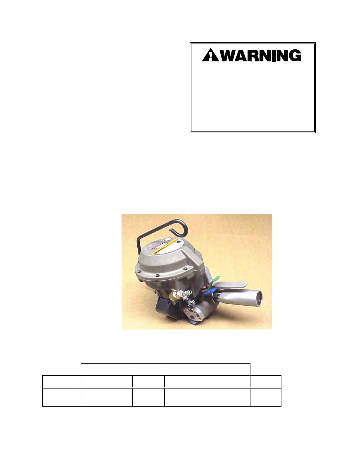
TABLE OF CONTENTS Page
General Safety Instructions 2
Specifications 4
Major Components 5
Recommended Air Line Piping 6
Maintenance 8
Set-Up for Tool Operation 9
Operating Instructions 10
Tool Parts Removal, Replacement
and Adjustments 14
Tool Parts List 20
Air Motor Parts List 28
Troubleshooting 34
Tool Options 37
Declaration Of Conformity 39
Signode tools and machines are designed
and warranted to work together with
Signode strapping and seals. Use of non Signode strap and seals and/or
manufactured or specified replacement
parts may result in strap breakage or joint
separation while applying strapping to a
load or during normal shipping and
handling. This could result in serious
personal injury.
PRHM-34
Part No. 306700
SPECIFICATIONS
STRAP
MODEL TYPE WIDTH THICKNESS SEALS
PRHM-34 MAGNUS,
PAINT & WAX
3/4"
(19mm)
0.025" (0.64mm) Minimum
0.031" (0.79mm) Maximum
34HOC
4
Page 5
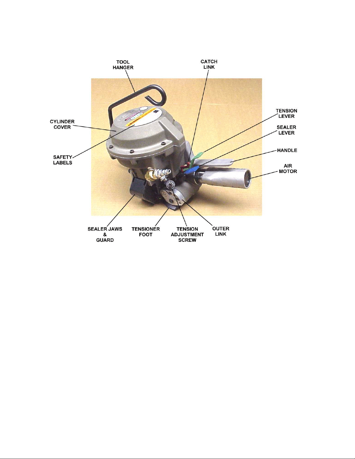
MAJOR TOOL COMPONENTS
5
Page 6
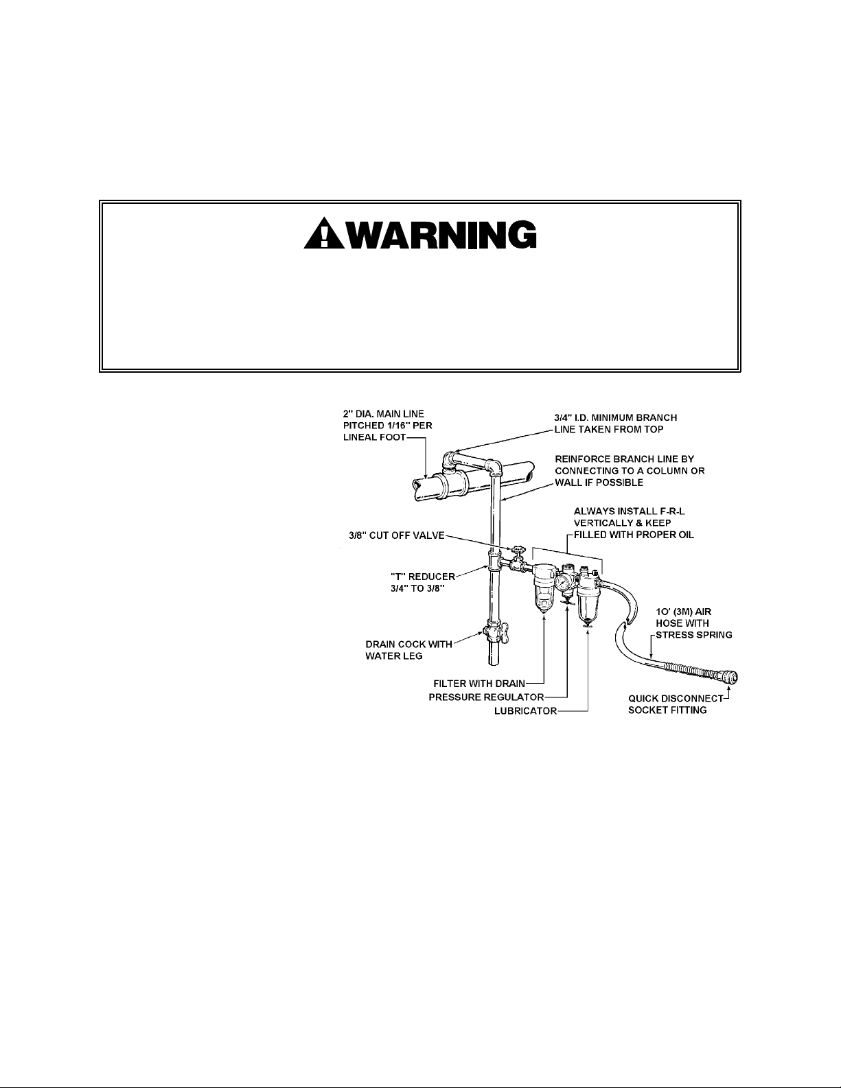
PNEUMATIC INFORMATION
AIR SUPPLY INSTALLATION
If compressor has a good dryer unit, use black pickled pipe. When a dryer unit is not installed,
use galvanized or copper pipe.
To perform reliably, a pneumatic tool requires a continuous source of clean, water-free air at
adequate pressure.
! Never operate this tool using a bottled air or gas source.
! Bottled air/gas sources do not provide consistent operating pressure and could result in
air pressures that exceed the maximum allowed for this tool.
! Exceeding the maximum allowable air pressure could result in serious personal injury.
A filter-regulator-lubricator unit
(Signode Part No. 173111) must
be installed as close to the air
tool as possible, preferably
within 10 feet (3M). It should be
placed in a convenient location
where it can easily be drained,
adjusted, and filled with oil. The
air hose must have at least a 1/4"
(6.3mm) I.D. A quick-connect
press-on socket is installed on
the stress spring end of the hose
for convenient hookup to the air
tool.
Filter and lubricator bowls are made of polycarbonate material. Do not install where bowls may
be exposed to materials incompatible with polycarbonate. Certain oils, solvents, and chemicals
or their fumes can weaken these bowls and possibly cause them to burst. Clean only with warm
water. A cut-off valve placed ahead of the filter will be useful when cleaning the filter or
replenishing the lubricator.
MOISTURE
Moisture is always present in air lines due to condensation within the lines as the air cools.
Steps must be taken to remove this moisture and to keep it from the air tool. This is because
water tends to wash away lubricants and cause corrosion, sticking and failure of internal parts.
The main line should be pitched so the far end terminates in a water leg. Branch lines are taken
from the top of the main, never off the bottom. Every branch should have a water leg at its
lowest point, with a drain cock which is drained daily.
6
Page 7

If these precautions are taken and water is still present, an after cooler and a moisture separator
are required between the compressor and the air receiver tank. A large air line separator can be
installed in the air tool line, but precautions must be taken to insure that it will be drained daily,
before the air tool is operated.
Water in air lines is a constant threat to the proper operation of air tools. Even near
freezing operating conditions, a good refrigerant type dryer is essential. A good dryer will
remove 95% or more of water right at the compressor. The remaining moisture is removed at the
water leg in the piping system or in the filter, Signode Part No. 173111. Additional information is
available in the Signode publication, "Air Supply Manual" p. 25, E-186038. If you have any
questions, contact your local Signode Representative.
LUBRICATION
The air motor must be properly lubricated. This is achieved by keeping the air line lubricator
filled with oil and correctly adjusted. Without proper lubrication, the motor will become sticky
and the tool will give low and erratic tension.
Install the lubricator as close to the air tool as possible. The arrow on the lubricator's top
surface must point in the direction of air flow.
For proper operation, oil must drop through the lubricator sight glass at a rate of 4 to 10 drops
per minute. This rate is to be checked while the air tool is running free. Only 20% of this oil is
actually delivered to the tool. The remaining oil drops back into the oil reservoir. The unit is
factory set and should require no adjustment. If an adjustment is required, the adjusting screw
on top of the lubricator may be turned as marked to reduce or increase the flow of oil.
The correct grade of oil must be used in the lubricator; too heavy an oil will not provide sufficient
lubrication and will cause sticking and sluggish operation of the air tool. Recommended oils are
any good grade of rust and oxidation inhibiting oil with a viscosity of 80-120 S.U.S. at 100
degrees Fahrenheit. (0.15 to 0.25 cm
2
/sec. at 38 degrees Celsius), such as:
Non Fluid Oil Co., grade #LS-1236
Signode oil - Part No. 008556
If necessary, use SAE #5 or SAE #10, non-detergent, cut 1:1 with kerosene. Some oils contain
anti-wear additives which may disable the air motor. Be certain to use recommended oil.
Several drops of lubricator oil added to the inlet of the air motor or into the air line each day will
help insure good operation. A noticeable reduction of air motor performance can usually be
corrected by squirting a few drops of oil into the air line.
AIR CONSUMPTION
Air consumption in cubic feet per minute
(cfm) for the PRHM-34 can be calculated as
follows: cfm = (a)x(b)x(0.23)
Example calculation:
Peak strapping load is 4 straps/minute, so
a = 4. Air motor is on 5 seconds/strap, so
b = 5. PRHM-34 efficiency ratio is 0.23.
a = Number of straps applied per minute.
b = Number of seconds air motor is on
per strap during tensioning, from
start to deceleration to stall.
(a)x(b)x(0.23)=4x5x0.23=4.6 cubic ft/min.
4x5x0.39=7.8 cubic meters/hr. (7.8M
3
/hr.)
0.23 = PRHM-34 efficiency ratio.
Air pressure is assumed to be 90 psig (6.2 bar) with the recommended size and length of air
hose. Volume of air at room temperature and sea level pressure, or so-called `free air'
conditions. For more detailed information about air supply systems, refer to Signode manual
Part No. 186038.
7
Page 8
PNEUMATIC INFORMATION, Continued
AIR PRESSURE vs. STRAP TENSION
Strap tension is controlled by air pressure. Use the proper air line piping and lubrication as
specified in this manual. Your air pressure gauge must be accurate, therefore, confirm its
accuracy by comparing it to a calibrated master gauge.
Strap breakage hazard. 3/4" (19mm) strap can break during tensioning if inlet air pressure to
the tool exceeds 70 psig. Strap breakage can result in serious personal injury. Maximum
operating pressure is 90 psig.
COLD WEATHER OPERATION
If a tool does not operate satisfactorily in freezing temperatures, certain steps can correct the
problem. The following steps can be taken to improve cold weather operation of the tool:
a. An air line dryer adjacent to the compressor.
b. Use lubricant recommended by Signode. Signode has tested the use of anti-freezes, none
work well in air tools; the tool will gum up when anti-freezes are introduced and will not
function properly. The best lubricant for freezing weather is the 1 to 1 oil and kerosene
combination.
c. If possible, run the air supply line to a indoor located Filter-Regulator-Lubricator or relocate
the F-L-R to a warmer operating area.
TOOL MAINTENANCE, CLEANING & LUBRICATION
Clean and apply a light weight machine oil to all moving parts on a weekly basis. Clean the
feedwheel daily with a wire brush. Refer to the Pneumatic Instructions for lubricant
recommendations with regard to the air motor.
Inspect all parts daily and replace them if they are worn or broken. Failure to do this can affect
a product's operation and could result in serious personal injury.
8
Page 9
SET-UP FOR TOOL OPERATION
STRAP TENSION
The PRHM-34 has been factory adjusted to
draw at least 1400 lbs. (6230N) of tension at
90 psig (6.2 bar). A minimum of 70 psig (4.8
bar) is required to ensure that the tool will
seal properly.
Strap tension is accurately controlled by air
pressure to the tool and the setting of the
adjusting screw. Use proper air line piping
and lubricant as specified in this manual.
Air pressure gauge must be accurate.
Confirm calibration at tool gauge by
comparing it to a master gauge.
Adjust strap tension as follows:
1. Make sure the air pressure is set
between 70 and 90 psig (4.8 - 6.2 bar).
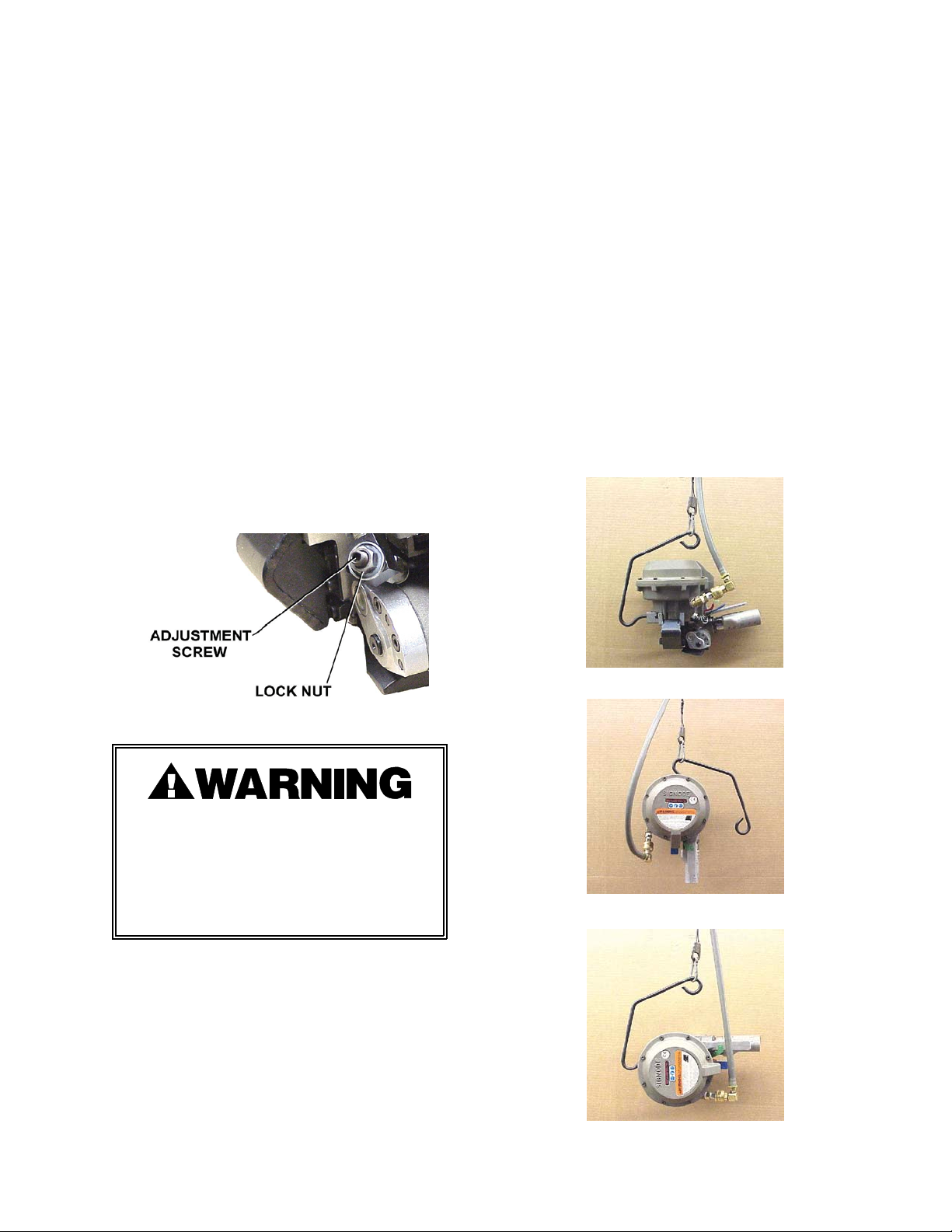
2. Loosen the lock nut and turn the
adjusting screw clockwise to decrease
tension and counterclockwise to
increase tension.
OPERATION POSITIONS
To work effectively, the PRHM-34 must be
properly oriented to the package. This
installation includes, in some cases, proper
suspension of the tool over the container to
be strapped and the proper placement of a
strapping dispenser to provide a continuous
easy supply of strapping for the application.
A spring loaded detent in the tool hanger
allows the tool to be rotated into several
different operating positions shown below.
To adjust the tool position, apply a steady
amount of force to the end of the hanger
bracket. The spring lock will then release
allowing the bracket to be moved to the next
position.
Three of the PRHM's most popular operating
positions are shown below:
Strap breakage hazard. Increasing the
tension can result in strap breakage and
could cause personal injury.
Never remove the adjusting screw from
the tool with the air connected. The
screw could become a flying projectile.
TOP SEALING
VERTICAL SEALING
HORIZONTAL SEALING
9
Page 10
OPERATING INSTRUCTIONS
! Wear safety glasses which conform to ANSI Standard Z87.1 or EN 166.
! Stand to one side of the strap while tensioning. Make sure all bystanders are clear before
proceeding.
! Failure to follow the above could result in serious personal injury.
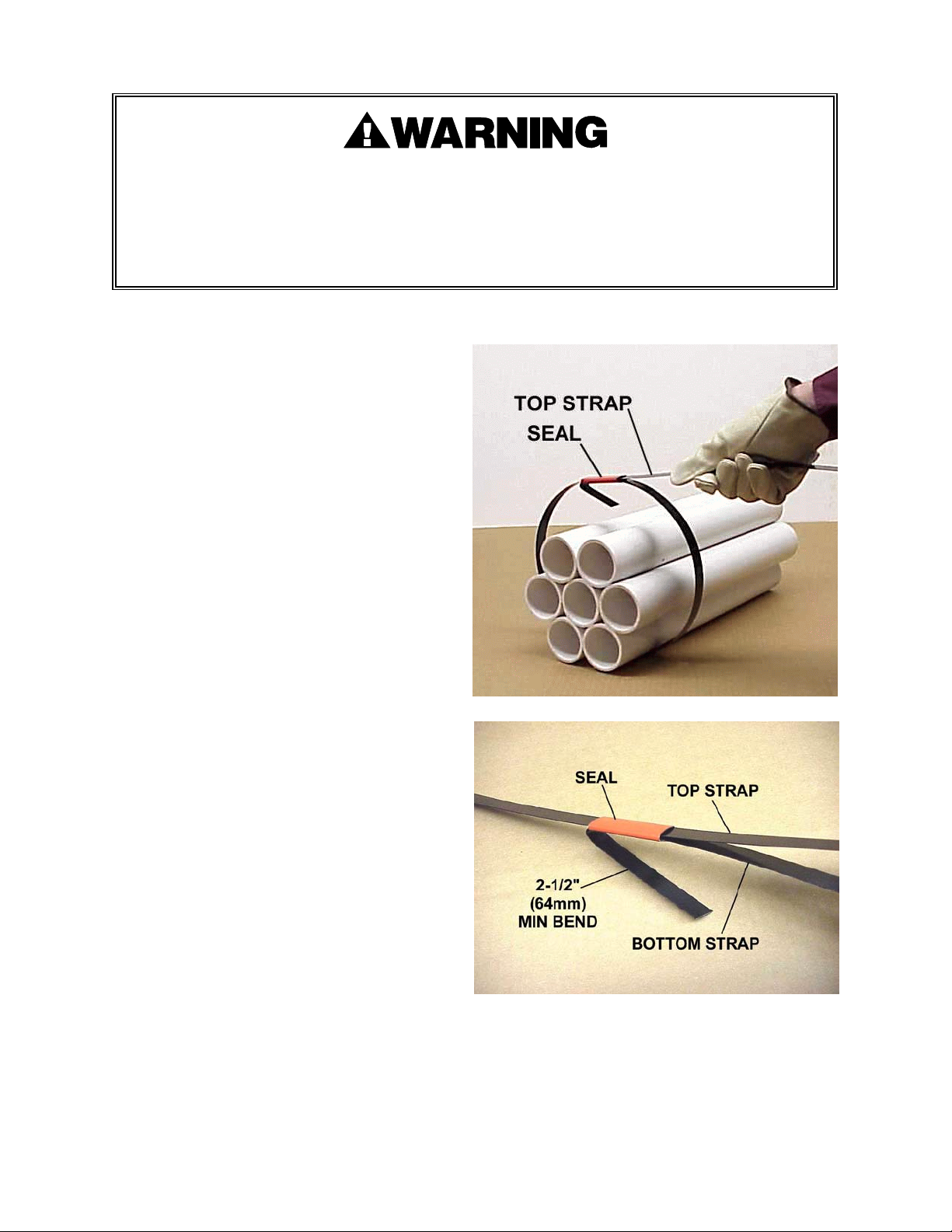
1. STRAP AND SEAL LOADING
Refer to the Specifications section on
page 4 to make sure the correct strap and
seal have been chosen. Insert the lead
end of the strap into the seal.
Pass the strap over the top of the package
then bring the lead end around and up
and rethread it into the seal. This will
result in creating a TOP STRAP and a
BOTTOM STRAP. They will be referred to
later in these instructions.
Bend a minimum of 2 1/2" (64mm) of the
lead end of the BOTTOM STRAP back
beneath the seal to maintain the loop.
Refer to Figure 1 to make sure the loop
has been properly formed. Hold the
BOTTOM STRAP and pull back on the
TOP STRAP to draw the loop loosely
around the package. A gentle upward
bend on the TOP STRAP will hold the loop
in place while the PRHM-34 tool is being
positioned.
10
Page 11
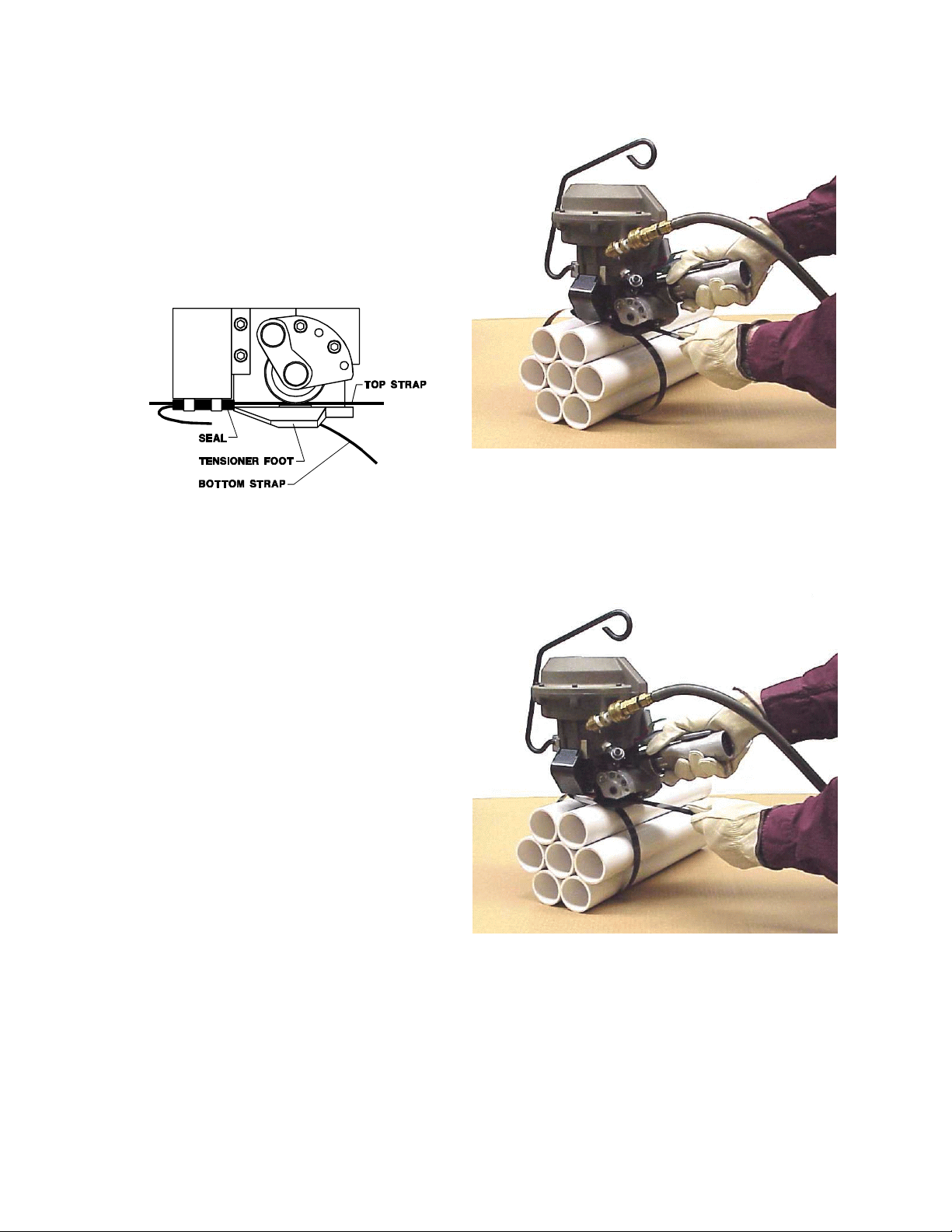
2. POSITIONING THE TOOL
Squeeze the handle and the air motor
together to create an opening between the
feedwheel and the tensioner foot. Grasp
the TOP STRAP and insert it sideways
into the tool between the feedwheel and
the tensioner foot. Make sure the strap
end is in contact with the inside surface of
the tensioner foot. When the TOP STRAP
is properly loaded, the sealing mechanism
will be in line with the seal.
Push the tool forward until the nose of the tensioner foot contacts the end of the seal.
3. REMOVING THE STRAP SLACK
Pull back on the TOP STRAP to eliminate
additional slack strap around the package.
NOTE: Before continuing, make sure the
TOP STRAP and the seal are still in
position, as described above. Note that
the BOTTOM STRAP will be positioned in
the channel on the bottom surface of the
breaker foot. This too, is necessary to
maintain strap alignment during tension.
Continued . . .
11
Page 12
OPERATING INSTRUCTIONS, Continued
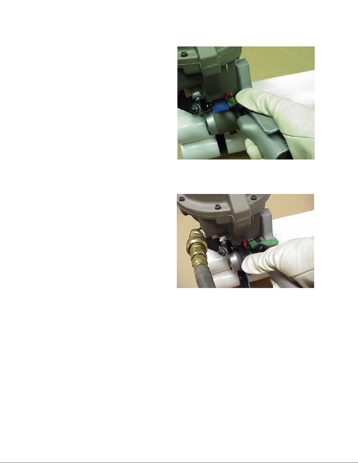
4. TENSIONING THE STRAP
While standing to one side of the strap,
press the tension lever (Green lever) all
the way down. The catch link will then
engage the tension lever holding it in the
down position.
The strap will tension around the package
until the proper tension level has been
reached, at which time the air motor will
stall. Refer to page 9 for detailed
information about adjusting strap tension.
NOTE: If strap alignment is unsatisfactory
and it becomes necessary to shut off the
tool during the tensioning portion of the
cycle, push the catch link (Red lever) over
to the left, releasing the tension lever. Cut
off the strap and apply a new strap in a
more favorable position.
5. FORMING THE STRAP JOINT
Press down and hold the sealer lever
(Blue lever). Air will be then routed to the
top of the cylinder enabling the sealer
mechanism to notch the seal/strap and
cut-off the TOP STRAP. The tool will
disengage from the seal and strapped
package leaving the cut off end of the
strap clamped under the feedwheel.
12
Page 13
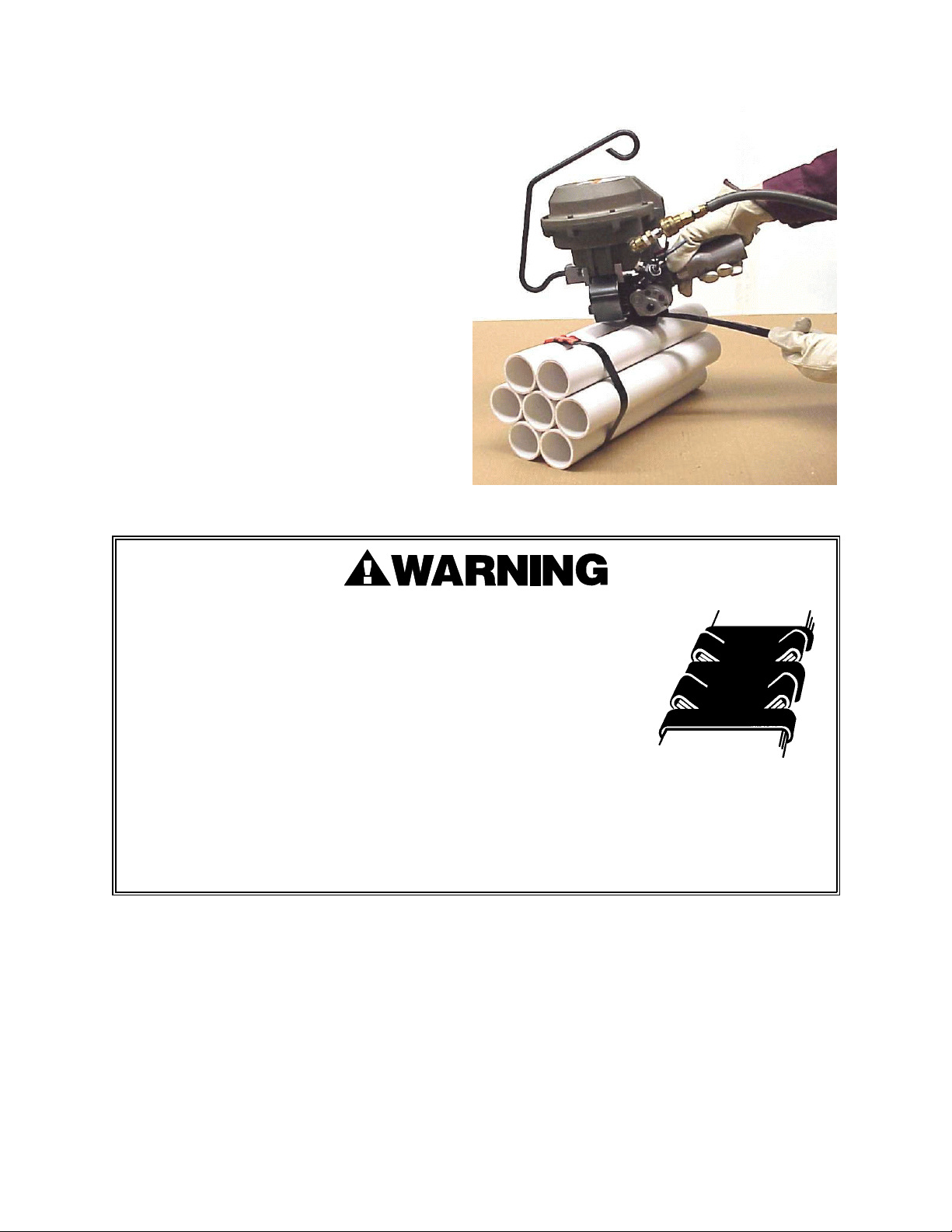
6. TOOL REMOVAL & JOINT INSPECTION
Squeeze the handle and the air motor
together to release the cut off strap end.
Lift the PRHM-34 tool from the tie and
closely inspect the joint to make sure the
tool has properly notched the seal. Refer
to Sealing Operation on the following
page for details regarding an acceptably
notched joint.
This tool is a double reverse notch-joint sealers. Each notch-joint
must be inspected to make certain it has four (4) good notches. A
properly formed notch-joint will appear as shown in the
illustration. If the notch-joint does not appear as shown, then the
operator must proceed as follows.
1. Make certain that the tool's operating instructions are being
followed before applying another strap.
2. Cut the strap off and apply a new strap and seal.
3. An improper formed seal which does not have four (4) good notches, could result in strap
separation. Before moving any package be certain that the seal is formed as shown.
Inspect the joint to make certain it appears as shown in the illustration. If not, remove the
broken strap and check the tool for worn or broken parts. Repair the tool for worn or
broken parts. Repair the tool before applying another strap.
13
Page 14
PART REMOVAL, REPLACEMENT & TOOL ADJUSTMENTS
The following procedure fully describes the disassembly of the PRHM-34. The instructions can
be reversed to assemble the tool. Please note that areas of the tool which require specific
adjustments for reassembly will be explained as well.
The disassembly instructions begin at a logical point for fully disassembling the tool, yet this is
not always necessary. Some disassembly procedures may be appropriately skipped in order to
avoid unnecessary labor.
Use the following instructions to disassemble the PRHM-34:
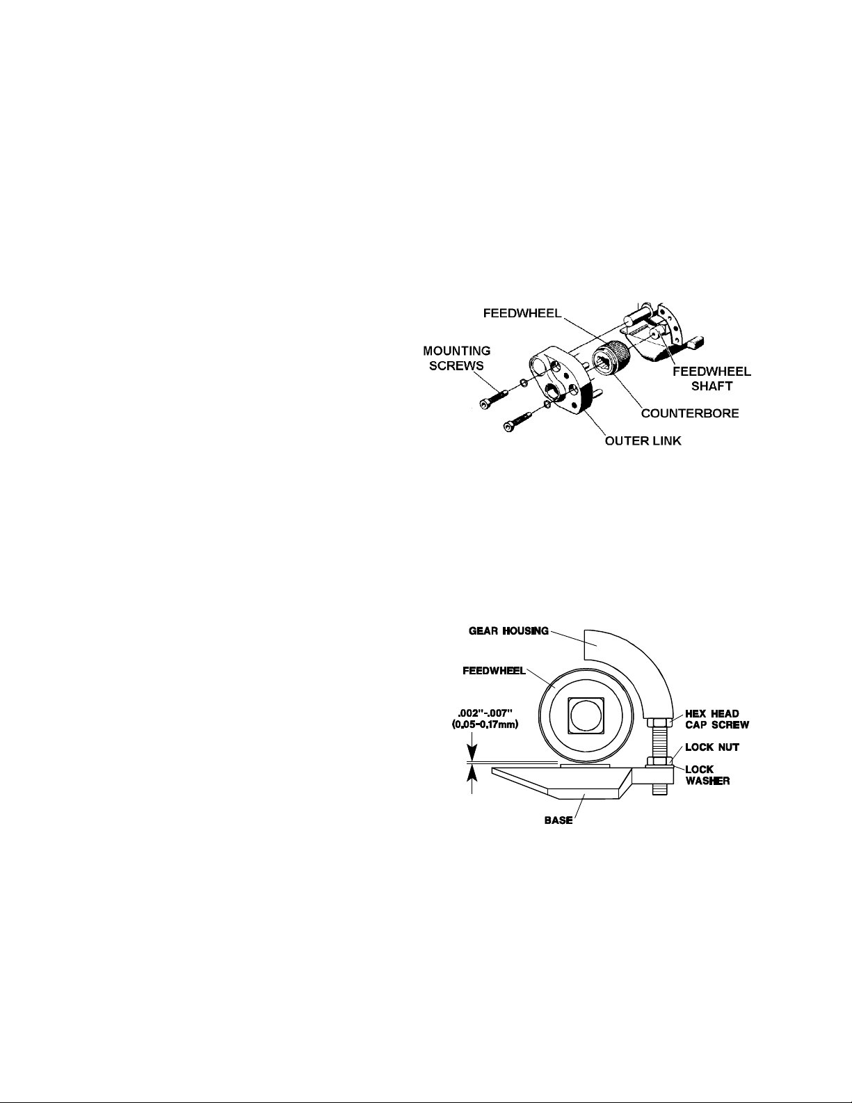
STEP 1 - FEEDWHEEL (For additional part information see pages 22 & 23)
1. To replace the feedwheel, remove the two
socket head cap screws which secure the
outer link. Remove the outer link from
the gear housing. Slide the feedwheel off
the feedwheel shaft. The counterbore
face of the feedwheel must face the outer
link in order to match up with the flange
bushing in the outer link.
2. Replace the feedwheel in the same manner in which it was removed. Feedwheel clearance
should be checked after replacing any parts associated with the tensioning system. This
clearance should be maintained to prevent the feedwheel from touching the wear pad and
encouraging early failure of these parts.
Feedwheel clearance can be set as follows:
a. Loosen the lock nut which secures the hex head adjustment screw which controls
feedwheel clearance.
b. Feedwheel clearance should be adjusted to
.002"-.007" (0.05mm-0.17mm) clearance.
Place an appropriate feeler gauge between
the feedwheel and the wear plug, turn the
hex head screw until the proper feedwheel
clearance has been reached.
c. When the clearance has been set, secure the hex head screw with the lock nut. Recheck
feedwheel clearance and adjust if necessary.
14
Page 15
PART REMOVAL, REPLACEMENT & TOOL ADJUSTMENTS, Continued
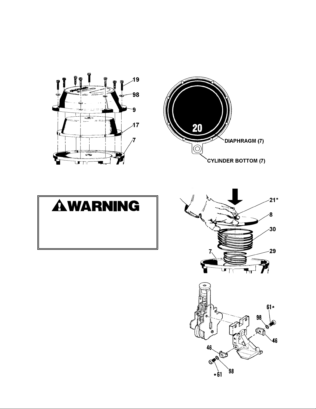
STEP 5 - SEALER MECHANISM (For additional part information see pages 22, 23, 24, 25)
1. With the hanger and guard assembly removed from the tool, turn the tool upright and remove
the eight cap screws (19) and washers (98) from the cover (9). Remove the cover and note
the position of the diaphragm (17) with the number "20" centered at the rear of the tool. This
positioning matches the screw holes in the cover and cylinder bottom with the cutouts in the
diaphragm.
2. Grip the cylinder bottom (7) and loosen the cap screw (21) that attaches the piston (8) to the
piston rod (39). Grip the piston firmly with one hand while removing the cap screw because
the two large springs (29,30) are compressed.
Compression springs (Keys 29 & 30) are
compressed and under tension. Use care
when removing the piston (Key 8). Failure to
follow the above could result in serious
injury to avoid personal injury.
3. Once the piston and springs have been removed,
the sealer mechanism along with the tensioner
foot, support plate, and cutter will drop out
from the bottom of cylinder. The tensioner
foot and cutter assembly will also separate
from the sealer assembly at this time. Set
these aside for later inspection.
* Secure with Loctite #242.
17
Page 16
TROUBLESHOOTING
The following items are the most common
tool symptoms if problems should occur.
For symptoms or remedies not shown,
contact your Signode service representative
for additional information and details. The
following tool symptoms are shown in this
manual:
#1 SYMPTOM: INADEQUATE STRAP TENSION
CAUSE REMEDY
1. Improper strap being used.
2. Incorrect tool operating pressure.
3. Tension regulator set too low.
4. Clogged air supply components.
#1 SYMPTOM: Inadequate strap tension.
#2 SYMPTOM: Feedwheel milling or slipping.
#3 SYMPTOM: Sealing & cut-off incomplete.
#4 SYMPTOM: Strap slips through seal.
#5 SYMPTOM: Low joint strength.
#6 SYMPTOM: Seal buckles w/ strap slipping.
#7 SYMPTOM: Seal slipping into nose of tool.
1. Check that Signode lubricated strap is
used.
2. Check that air pressure is set between
70-90 psig (4.8-6.2 bar).
3. Adjust tension regulator of tool.
4. Check for particles restricting air flow
in the regulator and filter (6).
5. Tool operating too dry.
6. Poor air delivery supply.
7. Wear plug interfeering with strap.
#2 SYMPTOM: FEEDWHEEL MILLING OR SLIPPING
CAUSE REMEDY
1. Feedwheel teeth packed with dirt or
grit.
2. Feedwheel teeth worn or chipped.
3. Feedwheel clearance is excessive.
4. Inspect feedwheel shaft DU bearing
(106) for extreme elongation.
5. Feedwheel mechanism does not pivot
freely.
5. Check lubricator operation and pour
6. Check for restrictions or deterioration
7. Check that wear plug (111) is not
1. Clean feedwheel teeth.
2. Check feedwheel (88). Replace if teeth
3. Check feedwheel clearance.
4. Replace DU bearing if necessary.
5. Check feedwheel pivoting for freedom
one tablespoon of lubricating oil into
tool inlet.
of supply hose.
gouging strap.
are broken or blunt.
of movement by squeezing the handle
and air motor together.
34
Page 17
#3 SYMPTOM: SEALING AND CUT-OFF IS INCOMPLETE
CAUSE REMEDY
1. Improper seals being used.
2. Incorrect tool operation pressure or
tension regulator set too low.
3. Worn or broken sealer mechanism.
4. Worn or broken diaphragm (17).
#4 SYMPTOM: LOWER STRAP SLIPPING THROUGH SEAL
CAUSE REMEDY
1. Check that the proper Signode seals
are being used (See page 4 of this
manual).
2. A minimum of 70 psig (4.8 bar) is
required to complete the sealing and
cut off cycle. See the illustration on
page 3 for the appearance of a
properly notched seal.
3. Check jaws (47), side plates (53, 56),
notcher (48), cutter (57), or leading
edge of tensioner foot (83). They
should be reasonably sharp. Replace
as required.
4. Check diaphragm (17) for holes or
tears. Replace if damaged.
1. Improper seals being used.
2. Incorrect tool operating pressure or
tension regulator set too high.
3. Strap tail is too short.
#5 SYMPTOM: LOW JOINT STRENGTH
CAUSE REMEDY
1. Improper seals being used.
2. Worn or broken sealer mechanism.
1. Check that the proper Signode seals
are being used (See page 4 of this
manual).
2. Decrease tension by adjusting
regulator of air motor.
3. Increase length of tail strap under
seal.
1. Check that the proper Signode seals
are being used (See page 4 of this
manual).
2. Replace worn or broken jaws,
notchers, side plates or pins.
35
Page 18
TROUBLESHOOTING, Continued
#6 SYMPTOM: LOWER STRAP SLIPPING THROUGH SEAL AND SEAL BUCKLES
CAUSE REMEDY
1. Improper seals being used.
2. Incorrect tool operating pressure or
tension regulator set too high.
#7 SYMPTOM: SEAL SLIPPING INTO THE NOSE OF TOOL.
CAUSE REMEDY
1. Improper seals being used.
2. Worn tensioner foot.
1. Check that the proper Signode seals
are being used (See page 4 of this
manual).
2. Decrease tension by adjusting
regulator on the air motor.
1. Check that the proper Signode seals
are being used (See page 4 of this
manual).
2. Check slot in tensioner foot (83). Slot
width should be .045" to .053"
(1.15mm - 1.35mm). If opening
exceeds this, check and replace if
necessary.
36
Page 19
EU Declaration of Conformity
The Supply of Machinery (safety) Regulations
1992 (S.I. 1992/3073)
It is hereby declared that the undermentioned machinery has been designed and
constructed to comply with the health and safety requirements defined in EC
Directive 89/292/EEC
Machine Supplier: Signode, Division of ITW Ltd.
Queensway, Fforestfach
Swansea SA5 4ED
Machine Description: PRHM-34
Machine Type: Pneumatic Combination Hand Strapping tool.
Provisions with which machine complies:
89/392/EEC, 91/368/EEC
Harmonized EuroNorms with which machine complies:
EN 292:1, EN 292:2, EN 294, EN 349
Technical Standards with which machine complies:
NA
Signature: Date: 8 NOV 1994
(Peter Oseland)
39
Page 20
SIGNODE
NEW TOOL WARRANTY
Signode Engineered Products Warrants that a new Signode strapping tool will operate per functional
specifications for a period of sixty (60) days after the date of shipment to the owner's place of business.
Normal wearing parts, as outlined in the Operation, Parts & Safety manual, are covered by a thirty (30)
day warranty unless, in Signode's judgement, these parts have been subjected to abnormal or extreme
usage. Signode's sole liability hereunder will be to repair or replace, without charge, F.O.B. Signode's
Glenview, Illinois plant, any tool which proves to not operate per functional specifications within the
stated period. Signode reserves the right to replace any tool which proves not to operate per functional
specifications with a new or like-new tool of the same model if in Signode's judgement such replacement
is appropriate. Any new replacement tool provided to an owner will carry a full sixty (60) day warranty.
Any warranty repaired tool or like-new replacement tool will carry a warranty for the balance of the time
remaining on the initial sixty (60) day warranty. This warranty will be extended to compensate for the
time the tool is in Signode's possession for warranty repairs.
This warranty is void as to any tool which has been: (I) subjected to mis-use, misapplication, accident,
damage, or repaired with other than genuine Signode replacement parts, (II) improperly maintained, or
adjusted, or damaged in transit or handling; (III) used with improperly filtered, unlubricated air or
improper strapping material, (IV) in Signode's opinion, altered or repaired in a way that affects or
detracts from the performance of the tool.
SIGNODE MAKES NO WARRANTY, EXPRESSED OR IMPLIED, RELATING TO MERCHANTABILITY,
FITNESS OR OTHERWISE EXCEPT AS STATED ABOVE AND SIGNODE'S LIABILITY AS ASSUMED ABOVE
IS IN LIEU OF ALL OTHERS ARISING OUT OF OR IN CONNECTION WITH THE USE AND PERFORMANCE
OF THE TOOL. IT IS EXPRESSLY UNDERSTOOD THAT SIGNODE SHALL IN NO EVENT BE LIABLE FOR
ANY INDIRECT OR CONSEQUENTIAL DAMAGES INCLUDING, BUT NOT LIMITED TO, DAMAGES WHICH
MAY ARISE FROM LOSS OF ANTICIPATED PROFITS OR PRODUCTION, SPOILAGE OF M ATERIALS,
INCREASED COSTS OF OPERATION OR OTHERWISE.
Considerable effort has be made to ensure that this product conforms to our high quality standards.
However, should you experience any difficulties, please contact your Sales Representative providing
samples and the manufacturing code specified on the tool.
Thank you for your help.
SIGNODE ENGINEERED PRODUCTS
Hand Tool Division
3620 W. Lake Avenue, Glenview, Illinois 60025
© Copyright 2002, Signode 286147 Rev. 10/2002
 Loading...