

Page 1
PN2-114 & PN2-2
IR POWERED TENSIONERS
A
SIGNODE !
3620 WEST LAKE AVENUE !
!
!!
! GLENVIEW, ILLINOIS 60026 U.S.A.
!!
Page 2

READ THESE INSTRUCTIONS CAREFULLY. FAILURE TO FOLLOW THESE INSTRUCTIONS CAN
R
ESULT IN SERIOUS PERSONAL INJURY.
STRAP BREAKAGE HAZARD
Improper operation of the tool or sharp corners on the load can result in strap
breakage during tensioning, which could result in the following:
! A sudden loss of balance causing you to fall.
! Both tool and strap flying violently towards your face.
Failure to place the strap properly around the load or an unstable or shifted load could result in a
sudden loss os strap tension during tensioning. This could result in a sudden loss of balance
causing you to fall.
! If the load corners are sharp use edge protectors.
! Positioning yourself in-line with the strap, during tensioning and sealing, can result in severe
personal injury from flying strap or tool. When tensioning or sealing, position yourself to one
side of the strap and keep all bystanders away.
TRAINING
This tool must not be used by persons not properly trained in its use. Be certain that you receive
proper training from your employer. If you have any questions contact your Signode
Representative.
EYE INJURY HAZARD
Failure to wear safety glasses with side shields can result in severe eye injury or
blindness. Always wear safety glasses with side shields which conform to ANSI
Standard Z87.1 or EN 166.
FALL HAZARD
Maintaining improper footing and/or balance when operating the tool can cause you to fall. Do
not use the tool when you are in an awkward position.
CUT HAZARD
Handling strap or sharp parts could result in cut hands or fingers. Wear protective
gloves.
TOOL CARE
! Inspect and clean the tool daily. Replace all worn or broken parts.
! Lubricate all moving parts weekly unless otherwise specified.
! On air powered tools, always disconnect the pneumatic connection to the tool when
performing part removal and replacement procedures. NEVER connect a pneumatic source to
a disassembled tool unless otherwise specified.
WORK AREAS
Keep work areas uncluttered and well lighted.
2
Page 3
READ THESE INSTRUCTIONS CAREFULLY. FAILURE TO FOLLOW THESE INSTRUCTIONS CAN
ESULT IN SERIOUS PERSONAL INJURY.
R
se correct Signode products for your application. If you need help contact your Signode
! U
Representative.
! Signode tools and machines are designed and warranted to work together with Signode
strapping and seals. Use of non-Signode strap and seals and/or manufactured or
specified replacement parts may result in strap breakage or joint separation while
applying strapping to a load or during normal shipping and handling. This could result in
severe personal injury.
JOINT FORMATION
! Before using this tool, read its Operation and Safety Instructions contained in this manual.
1. This tool can be used with a variety of Signode sealer tools. Read the sealer’s manual
thoroughly to inspect a formed seal joint. Each joint must be inspected to make certain it has
been properly made. A properly formed joint is shown in every sealer’s manual. If the joint
does not appear to have been made properly, then the operator must proceed as follows.
A. Make certain that the tool's operating instructions are being followed before applying
another strap.
B. Cut the strap off and apply a new strap and seal.
C. An improper formed seal which does not have good notches or crimps, could result in
strap separation. Before moving any package be certain that the seal is formed as shown
in the sealer’s manual. Inspect the joint to make certain it appears as shown in the
sealer’s manual. If not, remove the broken strap and check the tool for worn or broken
parts. Repair the tool for worn or broken parts. Repair the tool before applying another
strap.
MOVING AND STACKING STRAPPED LOADS
Before moving or stacking any strapped load, follow all standard industry practices regarding
safe material handling procedures.
CUTTING TENSIONED STRAP
Use only cutters designed for cutting strap; never use claw hammers, crowbars, chisels, axes or
similar tools. Such tools will cause the strap to fly apart with hazardous force. Before using any
Signode product read its Operation and Safety Manual.
3
Page 4
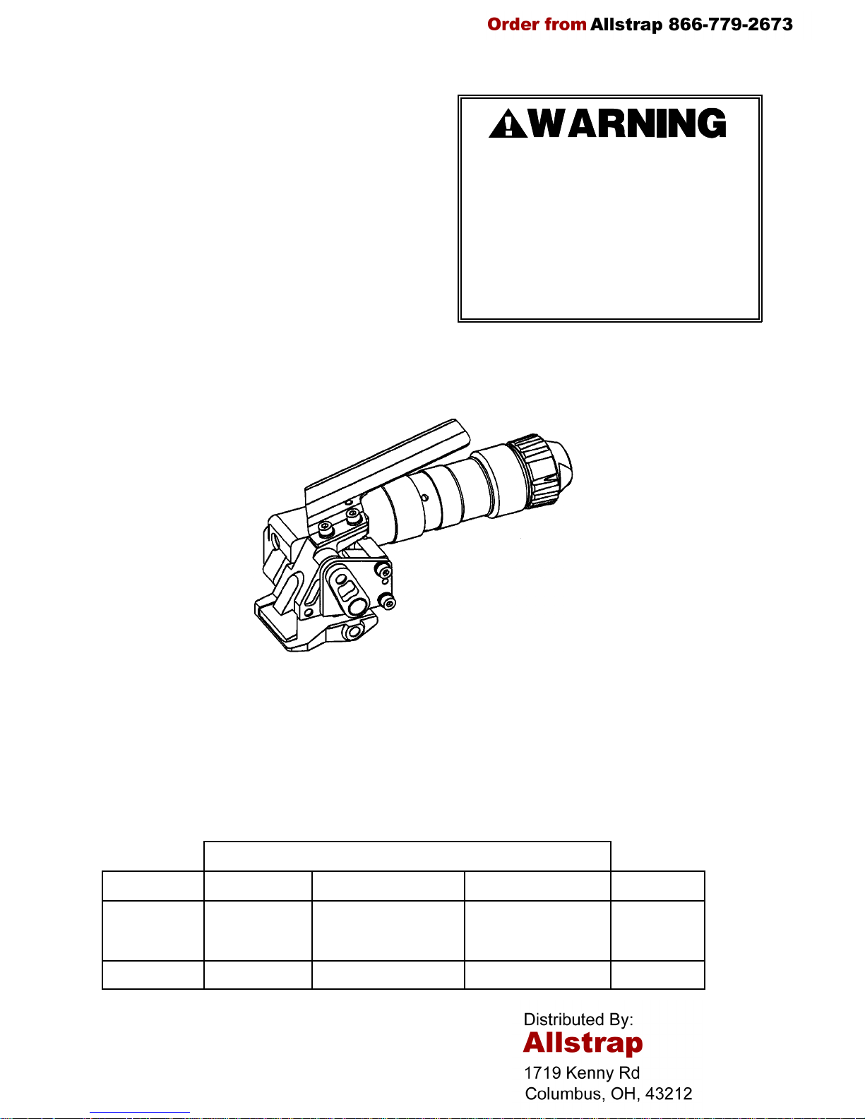
TABLE OF CONTENTS
G
eneral Safety Instructions 2
Specifications 4
Major Components 5
Installation 5
Maintenance 5
Pneumatic Information 6
Strap Tension 8
Operating Instructions 9
Parts List, Tool 12
Parts List, Gear Housing 14
Parts List, Air Motor 16
Declaration Of Conformity 19
Signode tools and machines are
d
esigned and warranted to work together
with Signode strapping and seals. Use of
non-Signode strap, seals and/or
manufactured or specified replacement
parts may result in strap breakage or
joint separation while applying strapping
to a load or during normal shipping and
handling. This could result in severe
personal injury.
PN2-114
Part No. 423500
(Patent No. 6,073,664)
PN2-2
Part No. 428360
(Patent No. 6,073,664)
SPECIFICATIONS
STRAP
MODEL TYPE WIDTH THICKNESS SEALS
PN2-114
Apex
&
Magnus
3/4"(19mm)
to
1-1/4"(31.75mm)
.020"(0.5mm)
to
.044"(1.12mm)
34HOC
114P
PN2-2 Magnus 2" (50mm) .044"(1.12mm) 208DG
4
Page 5
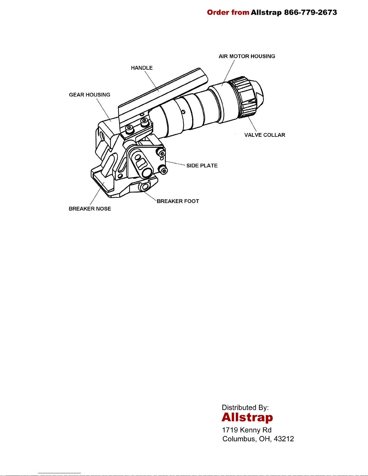
MAJOR COMPONENTS, PN2
T
OOL INSTALLATION
To work effectively, the tool must be properly installed. This installation includes the proper
placement of a strapping dispenser to provide a continuous supply of strap for the application
and a satisfactory air supply.
TOOL MAINTENANCE
Clean the tool daily with a brush and apply light machine oil to all the moving surfaces. The feed
wheel can be cleaned by holding a wire brush parallel to the face of the wheel while the tool is
running.
5
Page 6
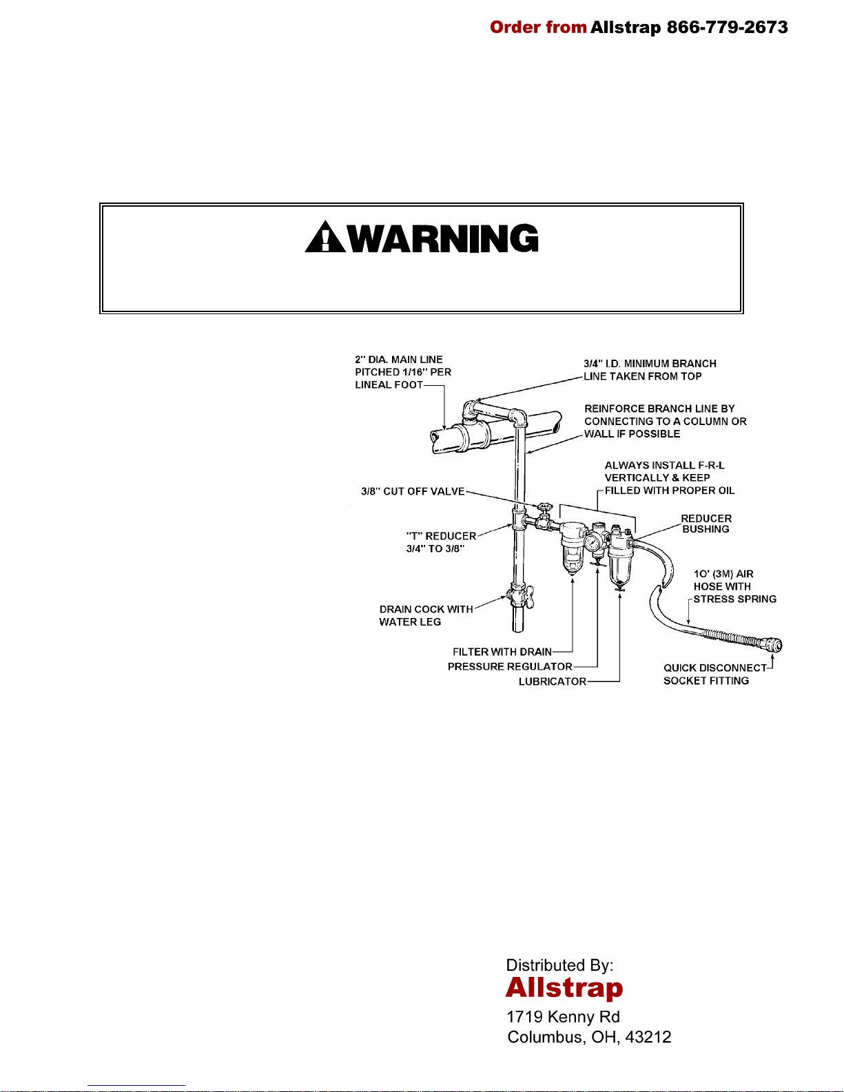
PNEUMATIC INFORMATION
A
IR SUPPLY INSTALLATION
If compressor has a good dryer unit, use black pickled pipe. When a dryer unit is not installed,
use galvanized or copper pipe. To perform reliably, a pneumatic tool requires a continuous
source of clean, water-free air at adequate pressure.
Never operate this tool using a bottled air or gas source.
Bottled air/gas sources do not provide consistent operating pressure
A filter-regulator-lubricator (FRL)
unit must be installed as close to
the air tool as possible, preferably
within 10 feet. It should be placed
in a convenient location where it
can easily be drained, adjusted, and
filled with oil. The air hose must
have at least a 3/8" I.D. A quick
disconnect socket fitting is installed
on the stress spring end of the hose
for convenient hookup to the air
tool.
Filter-Regulator-Lubricator Unit
(Signode Part No. 008559 or 173111)
FRL Mounting Bracket
(Signode Part No. 071982)
Air Hose, 3/8" ID, 1/4" Fittings
(Signode Part No. 008558)
Reducer Bushing, 3/8" to 1/4"
(Signode Part No. 008478)
Quick Disconnect, 1/4" Fitting
(Signode Part No. 020706)
Filter and lubricator bowls are made of polycarbonate material. Do not install where bowls may
be exposed to materials incompatible with polycarbonate. Certain oils, solvents, and chemicals
or their fumes can weaken these bowls and possibly cause them to burst. Clean only with warm
water. A cut-off valve placed ahead of the filter will be useful when cleaning the filter or
replenishing the lubricator.
6
Page 7

MOISTURE
Moisture is always present in air lines due to condensation within the lines as the air cools.
Steps must be taken to remove this moisture and to keep it from the air tool. This is because
water tends to wash away lubricants and cause corrosion, sticking and failure of internal parts.
The main line should be pitched so the far end terminates in a water leg. Branch lines are taken
from the top of the main, never off the bottom. Every branch should have a water leg at its
lowest point, with a drain cock which is drained daily. If these precautions are taken and water is
still present, an after cooler and a moisture separator are required between the compressor and
the air receiver tank. A large air line separator can be installed in the air tool line, but
precautions must be taken to insure that it will be drained daily, before the air tool is operated.
7
Page 8

Water in air lines is a constant threat to the proper operation of air tools. Even near freezing
operating conditions, a good refrigerant type dryer is essential. A good dryer will remove 95%
or more of water right at the compressor. The remaining moisture is removed at the water leg in
the piping system or in the filter (Part No. 008559).
NOTE: Additional information is available in the Signode publication, "Air Supply Manual" (Part
No. 186038). If you have any questions, contact your local Signode Representative.
LUBRICATION
The air tool must be properly lubricated. This is achieved by keeping the air line lubricator filled
with oil and correctly adjusted. Without proper lubrication, the tool will become sticky and will
be difficult to release from the strap.
Install the lubricator as close to the air tool as possible. The arrow on the lubricator's top
surface must point in the direction of air flow.
For proper operation, oil must drop through the lubricator sight glass at a rate of 4 to 10 drops
per minute. This rate is checked while the air tool is running free. Only 20% of this oil is actually
delivered to the tool. The remaining oil drops back into the oil reservoir. The unit is factory set
and should require no adjustment. If an adjustment is required, the adjusting screw on top of
the lubricator may be turned as marked to reduce or increase the flow of oil.
The correct grade of oil must be used in the lubricator; too heavy an oil will not provide sufficient
lubrication and will cause sticking and sluggish operation of the air tool.
Recommended oils are any good grade of rust and oxidation inhibiting oil with a viscosity of 80120 S.U.S. at 100 degrees Fahrenheit. (0.15 to 0.25 cm2 /sec. at 38 degrees Celsius), such as:
Non Fluid Oil Co., grade #LS-1236
Signode oil - Part No. 008556
If necessary, use SAE #5 or SAE #10 non-detergent, cut 1 to 1 with kerosene.
NOTE: Some oils contain anti-wear additives which may disable the tool. Be certain to use
recommended oil.
Several drops of lubricator oil added to the inlet of the air line each day will help insure good
operation. A noticeable reduction of performance can usually be corrected by squirting a few
drops of oil into the air line.
COLD WEATHER OPERATION
If a tool does not operate satisfactorily in freezing temperatures, certain steps can correct the
problem. The following steps can be taken to improve cold weather operation of the tool:
a. An air line dryer adjacent to the compressor.
b. Use lubricant recommended by Signode. Signode has tested the use of anti-freezes, none
work well in air tools; the tool will gum up when anti-freezes are introduced and will not
function properly. The best lubricant for freezing weather is the 1 to 1 oil and kerosene
combination.
c. If possible, run the air supply line to a indoor located Filter-Regulator-Lubricator or relocate
the F-L-R to a warmer operating area.
8
Page 9
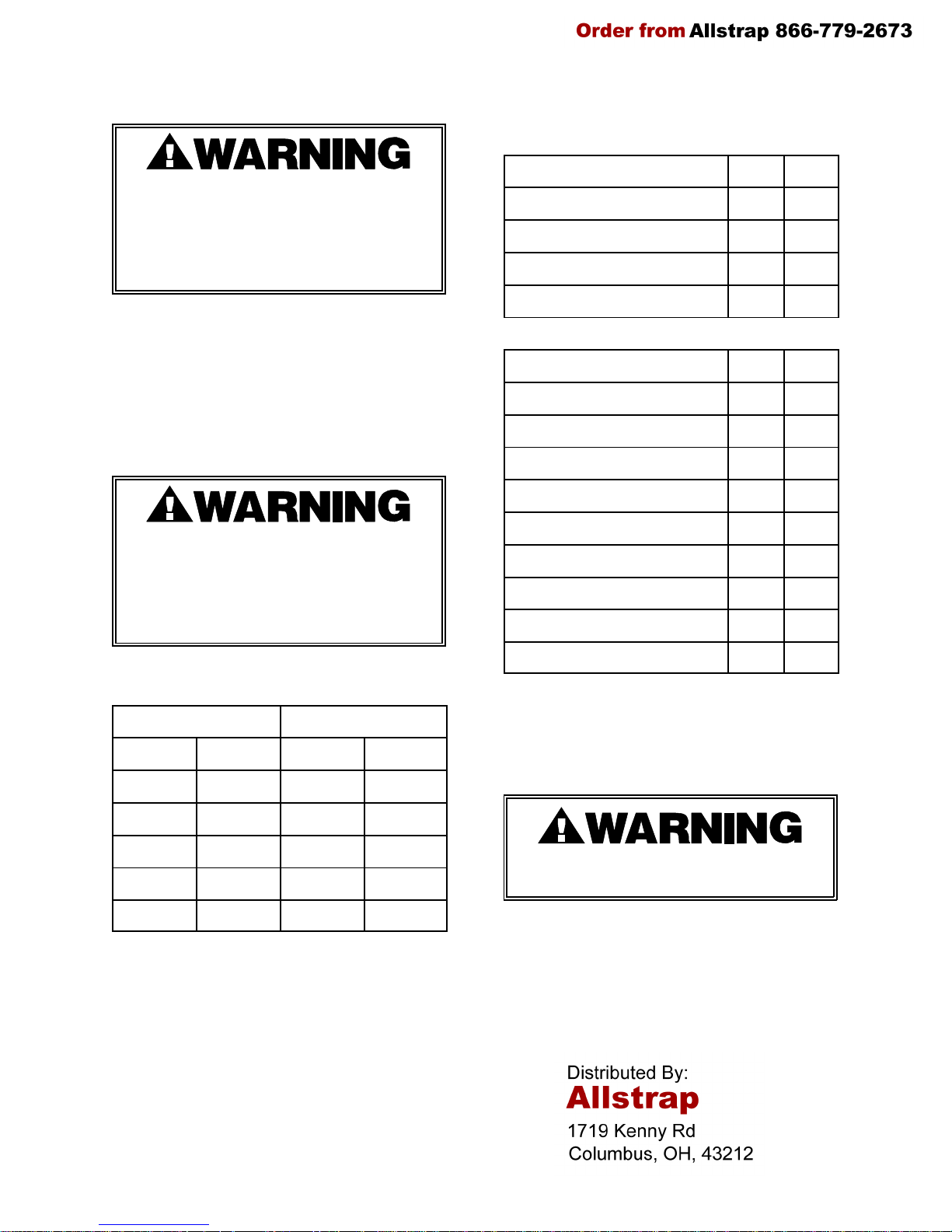
STRAP TENSION
RECOMMENDED AIR PRESSURE
Failure to use the proper strap/seal/tool
combination for the load being strapping
can result in an improperly secured load
which can result in severe personal
injury. If you have any questions, contact
your local Signode Representative.
Strap tension is controlled by air pressure.
Adjust the pressure regulator to give the
desired tension level. Once the regulator is
set, tension will be uniform on all straps
provided the operator allows the air motor to
stall. The air pressure gauge must be
accurate. Confirm calibration by comparing
it to a master gauge.
Strap breakage hazard. Increasing the
tension can result in strap breakage. If a
strap breaks during tensioning, reduce
the air pressure by 5 psi (0.35 Bar)
increments until the strap does not
break.
APEX psig Bar
3/4 x .020 (19 x .51mm) 55 3.7
3/4 x .023 (19 x .58mm) 55 3.7
3/4 x .028 (19 x .71mm) 80 5.5
3/4 x .035 (19 x .89mm) 80 5.4
MAGNUS psig Bar
3/4 x .020 (19 x .51mm) 75 5.1
3/4 x .025 (19 x .64mm) 80 5.5
3/4 x .031 (19 x .79mm) 85 5.8
3/4 x .035 (19 x .89mm) 85 5.8
3/4 x .044 (19 x 1.1mm) 85 5.8
1-1/4x.031 (31.75 x .79mm) 90 6.2
1-1/4x.035 (31.75 x .88mm) 90 6.2
1-1/4x.044 (31.75 x 1.1mm) 90 6.2
APPROXIMATE STRAP TENSIONS
AIR PRESSURE TENSION
psig Bar lbs. Newtons
90 6.2 1600 7104
80 5.5 1425 6327
70 4.8 1200 5328
60 4.1 1050 4662
50 3.4 900 3996
2 x .044 (50 x 1.1mm) 90 6.2
If the above air pressures do not result in
tension levels that satisfy your strapping
needs, then increase the air pressure in
increments of 5 psig (.34 Bar) until desired
tensions are achieved.
Do not exceed 90 psig (6.2 Bar) input air
pressure to the tool.
9
Page 10
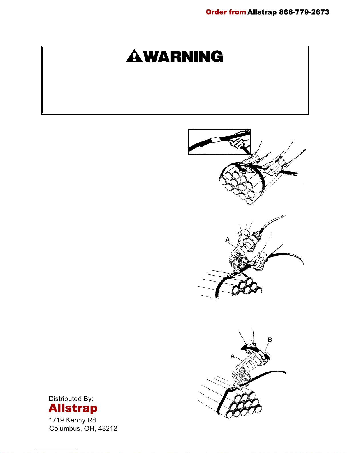
OPERATING INSTRUCTIONS
B
efore operating this tool, make sure it has been properly maintained as noted in the
Maintenance section of this manual.
Wear safety glasses. Always position yourself to one side of the strap. Make sure all
bystanders are clear before proceeding.
Failure to follow the above could result in severe personal injury.
1. Thread the strap through a Signode full overlap
push type seal. Encircle the bundle and
rethread the strap end through the seal as
shown. Bend the strap end back sharply under
the seal, about 2 ½ inches, and pull out the
slack strap.
! For 3/4" strap use #34HOC Seals.
! For 1-1/4" strap use #114P seals.
! For 2" strap use #208DG seals.
2. Press the gripper lever (A) with palm. Place the top strap into
the front nose opening and slide the tool forward until it butts
against the seal.
3. While standing to one side of the strap line, release the gripper
lever (A) and turn the air control ring (B) in the direction of the
arrow with the palm of the hand. The tool will automatically
tension the strap and hold it tight.
10
Page 11
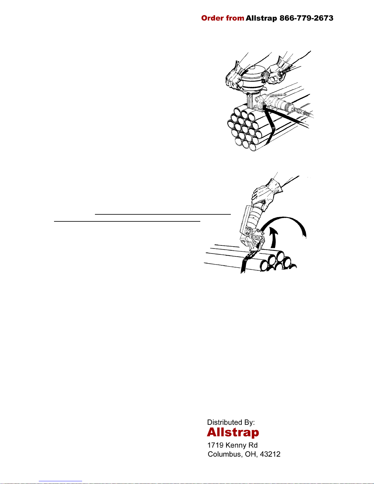
OPERATING INSTRUCTIONS, Continued
4
. Notch the seal with a sealing tool. Note that the
tensioner automatically keeps tension on the strap.
Inspect the seal to make sure the sealing tool has
properly formed a joint.
5. Before shutting of the air , break the strap at the seal by swinging
the tensioner up and down as shown. DO NOT EXCEED 90
o
MOVEMENT. If the tool is swung too far forward, damage to
the seal will occur and the strap will not break off.
11
Page 12
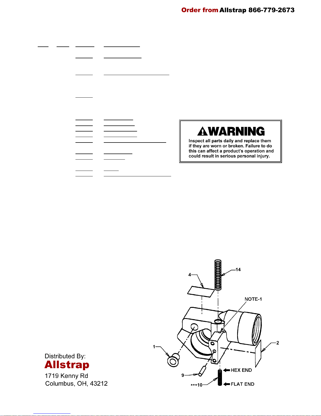
PARTS LIST, TOOL
K
1 1 423518 Flange bearing
2 1 423537 Nameplate (PN2-114)
3 1 423516
4 1 267596 Warning plate
5
6 2 423549 SHCS, M6 x 18
7 1 423532
8
9 1 162391 Pin, k5mm x 24mm
10 1 423791 SHSS, M6 x 25 (flat point)
14 1 423548
16 1 423514 Breaker foot
17 1 423513 Breaker nose (PN2-114)
8 1 252262
1
19 1 423546 Nose spring
0 1 423398
2
21 1 423521 Bushing
22 1 423505 Side plate
6 1 423517
2
28 1 423524 Roller pin,
!
QTY. PART # DESCRIPTION
EY
1
4 005464 Lock washer
2 423790 SHCS, M6 x 25
1
When ordering parts please show tool model, part number and description.
510462 Nameplate (PN2-2)
k
10mm x 60mm
k
8mm x 36mm
k
10mm x 50mm
428486
Pivot pin,
Handle
Foot spring
Breaker nose (PN2-2)
Nose pin,
Feed wheel
Roller
! Recommended spare parts are underlined and should be stocked.
! Common hardware parts can be obtained at any local hardware supply.
* Apply one drop of Loctite #242 (Blue) sealant to cleaned parts. Allow 12 hours to set if possible.
Do not apply to small screws or close to moving parts as liquid spreads easily.
** Apply one drop of Loctite #271 (Red) sealant to cleaned parts. Allow 12 hours to set if
possible. Do not apply to small screws or close to moving parts as liquid spreads easily.
*** Apply one drop of Loctite #222 (Purple) sealant to cleaned parts. Allow 12 hours to set if
possible. Do not apply to small screws or close to moving parts as liquid spreads easily.
NOTES:
1. Allen wrench access hole to socket head set screw
(Key 10) for feedwheel to roller clearance
adjustment.
2. Install feedwheel in noted rotational direction as
shown by arrows.
3. Install roller with the larger diameter (marked
OUT) facing outwards as shown.
12
Page 13
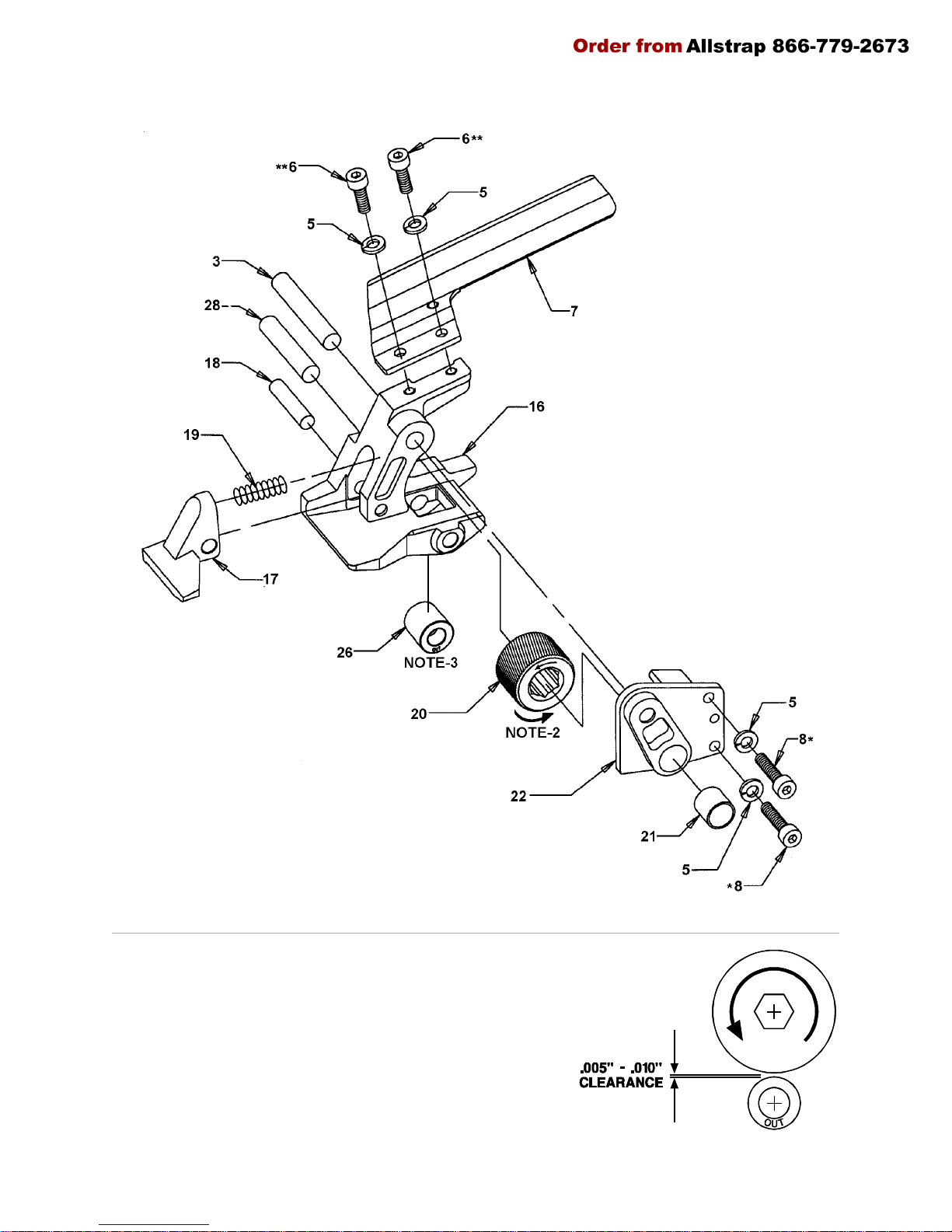
FEEDWHEEL TO ROLLER CLEARANCE:
he feedwheel (Key 20) to roller (Key 26) clearance is set by
T
turning the set screw (Key 10) until there is a .005" - .010"
clearance to be established between the two parts.
NOTE: The feedwheel and roller
should note come together.
13
Page 14
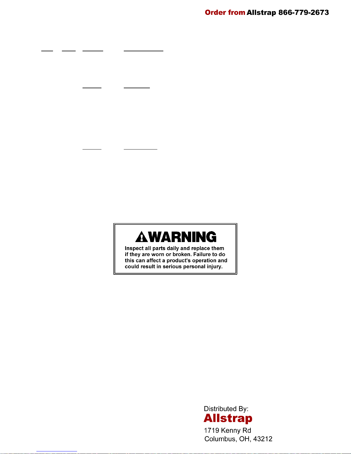
PARTS LIST, GEAR HOUSING ASSEMBLY, PART NO. 423520
K
1 1 008781 Thrust washer
2
3 1 008871 Ring gear
4 1 008769 Spacer
5 3 008766
7 1 306389 Idler gear plate assembly
8
9 1 008774 Key
10 1 423530 Worm
11 1 423511 Gear housing
12 1 008751 Needle bearing, Torr M781
13 1 008752 Truarc, N5000-62
14 1 423515 Bearing, Fafnir B539DD
15 1 024038 Bearing, Fafnir KP10A
16 1 423529
17 1 423501 Feedwheel shaft
8 1 423509 Cover
1
19 1 250731 Truarc ring, N5000-185
20 1 256755 O-Ring, SAE 30
21 1 423531 O-Ring, SAE 18
22 1 423533 Thrust washer
QTY. PART # DESCRIPTION
EY
1 008872 Ring gear key
Idler gear
1 008756 Bearing, Fafnir 7203
Worm - gear
! When ordering parts please show tool model, part number and description.
! Recommended spare parts are underlined and should be stocked.
! Common hardware parts can be obtained at any local hardware supply.
14
Page 15
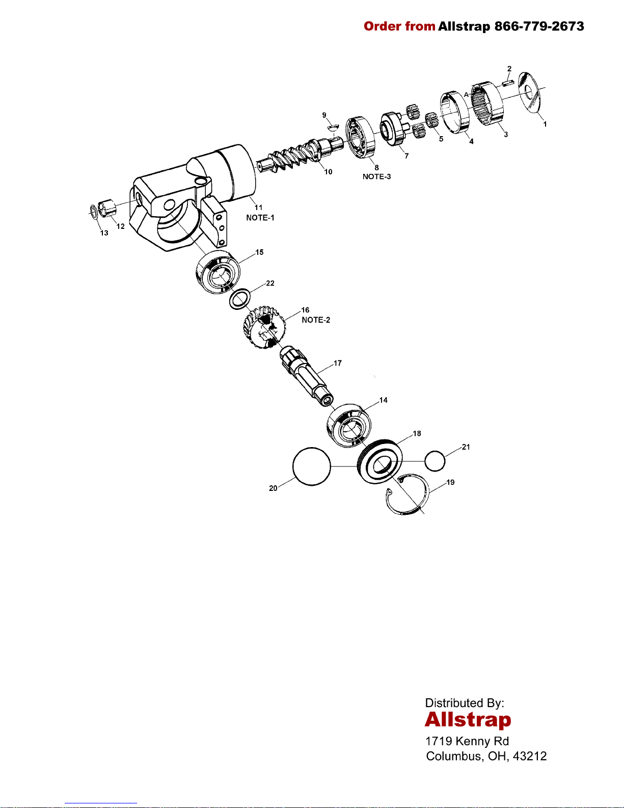
NOTES:
. Pack the gear housing (11) about 1/3 full with Non-Fluid Oil #K55 or equivalent.
1
2. When assembling the worm gear, the side stamped 'T' must face towards the back of the
housing.
3. Bearing must be installed with wide shoulder away from worm.
15
Page 16
PARTS LIST, AIR MOTOR 100L15, PART NO. 423510
KEY QTY. PART NO. DESCRIPTION
1 1 024631 Filter assembly
2
3 1 024676 Valve collar
4 1 024662
5 1 023559 O-ring
6 1 023549 Retainer
7
8 1 004164
9 1 423508 Motor housing
0 1 023372 Roll pin, 3/16 x 3/8
1
11 1 024661 Valve spring
12 1 423534 Deflector assembly
13 1 024633
14 1 024653 Back end plate
15 1 024652 Cylinder
6 1 423423
1
17 5 024651 Vane
8 1 024602 Spacer
1
19 1 023510 Align pin
20 1 423794
1 1 023481 Ball bearing
2
22 1 023547 Ball bearing
24 1 423403 Idler carrier assembly
25 3 423060
26 1 423798 Ring gear
7 1 023558 Seal
2
28 1 423404 Spacer
29 2 423793 Bevel spring washer
30 1 306612 Pin
31 1 423795 Gear housing
33 1 286373 3 symbol safety sign
34 1 280537 On-Off label
1 023557 Retainer, Spirolox, #RS-181
Valve stem
1 024663 Valve sleeve
O-ring
Bearing, Fafnir, #ASIK7-SRI #2
Rotor
Front end plate
Idler
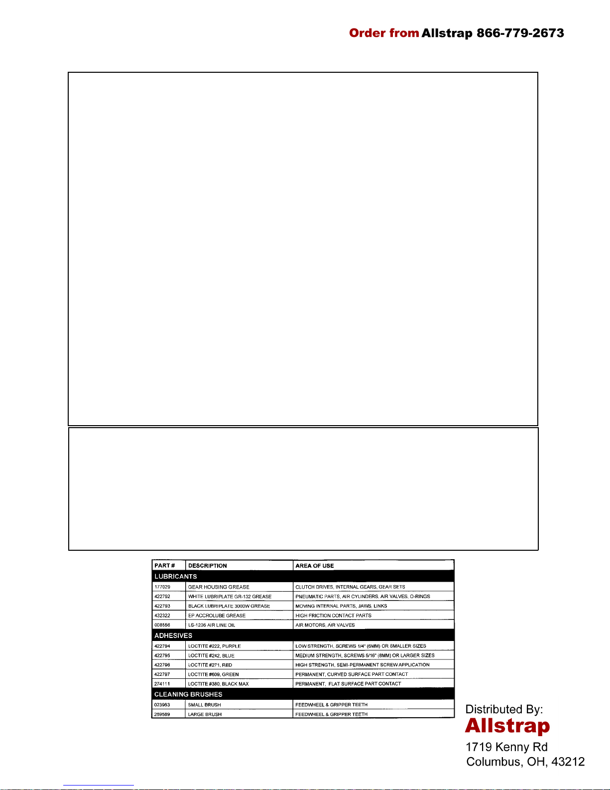
! When ordering parts please indicate air motor model, part number and description.
! Recommended spare parts are underlined and should be stocked.
! Common hardware parts can be obtained at any local hardware supply.
NOTES:
1. Align marks on motor housing as indicated in “View A-A”.
2. Location of air motor number (underside).
3. Idler gears (25) are to be lubricated with Non-Fluid Oil #K55 or equivalent. Vanes (17)
must soak in air line oil overnight before assembling air motor.
4. If the rear motor housing (9) becomes loose, it must be retightened while the motor is
running at 20 to 30 psig (1.6 to 2.0 Bar) air pressure. This will ensure proper alignment
and rotor freedom.
5. Spring washers should be assembled back to back with cup shape facing outwards )( .
6. Apply labels (Key 33 & 34) to motor housing oriented as shown in “View B”.
16
Page 17
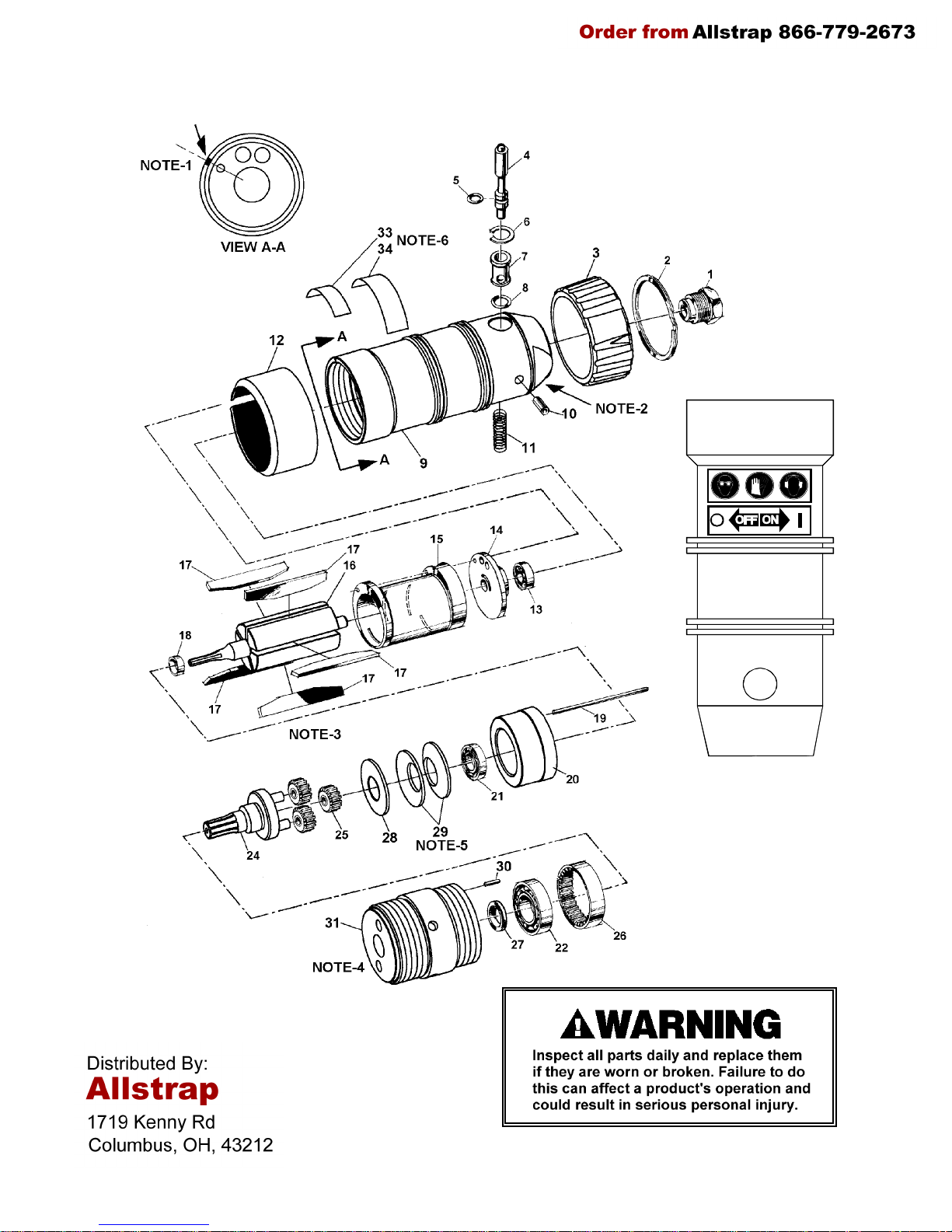
VIEW B
17
Page 18

18
Page 19
EU Declaration of Conformity
he Supply of Machinery (safety) Regulations
T
1992 (S.I. 1992/3073)
It is hereby declared that the undermentioned machinery has been designed and
constructed to comply with the health and safety requirements defined in EC Directive
89/392/EEC
Machine Supplier: Signode, Division of ITW Ltd.
Queensway, Fforestfach
Swansea SA5 4ED
Machine Description: PN2
Machine Type: Pneumatic Tensioner Hand Strapping tool.
Provisions with which machine complies:
89/392/EEC, 91/368/EEC
Harmonized EuroNorms with which machine complies:
EN 292:1, EN 292:2, EN 294, EN 349
Technical Standards with which machine complies:
NA
Signature: Date: 1 MARCH 2000
(Peter Oseland)
19
Page 20
SIGNODE
NEW TOOL WARRANTY
Signode Engineered Products Warrants that a new Signode strapping tool will operate per functional
specifications for a period of sixty (60) days after the date of shipment to the owner's place of business.
Normal wearing parts, as outlined in the Operation, Parts & Safety manual, are covered by a thirty (30)
day warranty unless, in Signode's judgement, these parts have been subjected to abnormal or extreme
usage. Signode's sole liability hereunder will be to repair or replace, without charge, F.O.B. Signode's
Glenview, Illinois plant, any tool which proves to not operate per functional specifications within the
stated period. Signode reserves the right to replace any tool which proves not to operate per functional
specifications with a new or like-new tool of the same model if in Signode's judgement such replacement
is appropriate. Any new replacement tool provided to an owner will carry a full sixty (60) day warranty.
Any warranty repaired tool or like-new replacement tool will carry a warranty for the balance of the time
remaining on the initial sixty (60) day warranty. This warranty will be extended to compensate for the
time the tool is in Signode's possession for warranty repairs.
This warranty is void as to any tool which has been: (I) subjected to mis-use, misapplication, accident,
damage, or repaired with other than genuine Signode replacement parts, (II) improperly maintained, or
adjusted, or damaged in transit or handling; (III) used with improperly filtered, unlubricated air or
improper strapping material, (IV) in Signode's opinion, altered or repaired in a way that affects or
detracts from the performance of the tool.
SIGNODE MAKES NO WARRANTY, EXPRESSED OR IMPLIED, RELATING TO MERCHANTABILITY,
FITNESS OR OTHERWISE EXCEPT AS STATED ABOVE AND SIGNODE'S LIABILITY AS ASSUMED ABOVE
IS IN LIEU OF ALL OTHERS ARISING OUT OF OR IN CONNECTION WITH THE USE AND PERFORMANCE
OF THE TOOL. IT IS EXPRESSLY UNDERSTOOD THAT SIGNODE SHALL IN NO EVENT BE LIABLE FOR
ANY INDIRECT OR CONSEQUENTIAL DAMAGES INCLUDING, BUT NOT LIMITED TO, DAMAGES WHICH
MAY ARISE FROM LOSS OF ANTICIPATED PROFITS OR PRODUCTION, SPOILAGE OF MATERIALS,
INCREASED COSTS OF OPERATION OR OTHERWISE.
Considerable effort has be made to ensure that this product conforms to our high quality standards.
owever, should you experience any difficulties, please contact your Sales Representative providing
H
samples and the manufacturing code specified on the tool.
Thank you for your help.
SIGNODE ENGINEERED PRODUCTS
Hand Tool Division
3620 W. Lake Avenue, Glenview, Illinois 60026
© Copyright 2010, Signode 437129 Rev. 3/2010
 Loading...