

Signode RCN-3435, RCN-1431, N-1435, NS-1457-75L, NS-250-65L Operation, Safety And Parts Manual
...
RCN-3435, RCN-1431, N-1435,
N-1444-50LSH, N-1457LSH,
NS-1457-75L, NS-250-65L
AIR POWERED SEALERS
READ ALL INSTRUCTIONS BEFORE OPERATING THIS SIGNODE PRODUCT
SIGNODE ! 3620 WEST LAKE AVENUE ! GLENVIEW, ILLINOIS 60025
READ THESE INSTRUCTIONS CAREFULLY. FAILURE TO FOLLOW THESE INSTRUCTIONS CAN
RESULT IN SEVERE PERSONAL INJURY.
GENERAL SAFETY CONSIDERATIONS
1. STRAP BREAKAGE HAZARD.
Improper operation of the tool or sharp corners on the load can result in strap breakage during
tensioning, which could result in the following:
!
A sudden loss of balance causing you to fall.
!
Both tool and strap flying violently towards your face.
Failure to place the strap properly around the load or an unstable or shifted load could result in
a sudden loss of strap tension during tensioning. This could result in a sudden loss of
balance causing you to fall.
!
If the load corners are sharp use edge protectors.
!
Positioning yourself in-line with the strap, during tensioning and sealing, can result in
severe personal injury from flying strap or tool. When tensioning or sealing, position
yourself to one side of the strap and keep all bystanders away.
2. TRAINING.
This tool must not be used by persons not properly trained in its use. Be certain that you
receive proper training from your employer. If you have any questions contact your Signode
Representative.
3. EYE INJURY HAZARD.
Failure to wear safety glasses with side shields can result in severe eye injury
or blindness. Always wear safety glasses with side shields which conform to
ANSI Standard Z87.1 or EN 166.
4. FALL HAZARD.
Maintaining improper footing and/or balance when operating the tool can cause you to fall. Do
not use the tool when you are in an awkward position.
5. CUT HAZARD.
Handling strap or sharp parts could result in cut hands or fingers. Wear
protective gloves.
6. TOOL CARE.
!
Inspect and clean the tool daily. Replace all worn or broken parts.
!
Lubricate all moving parts daily.
!
On air powered tools, always disconnect the pneumatic connection to the tool when
performing part removal and replacement procedures. NEVER connect a pneumatic source
to a disassembled tool unless otherwise specified.
7. WORK AREA.
Keep work areas uncluttered and well lighted.
2
Use the correct Signode products for your application. If you need help contact your
Signode Representative.
Signode tools and machines are designed and warranted to work together with Signode
strapping and seals. Use of non-Signode strap, seals and/or manufactured or specified
replacement parts may result in strap breakage or joint separation while applying strapping
to a load or during normal shipping and handling. This could result in severe personal injury.
JOINT FORMATION
1. Before using this tool, read its Operation and Safety Instructions
contained in this manual.
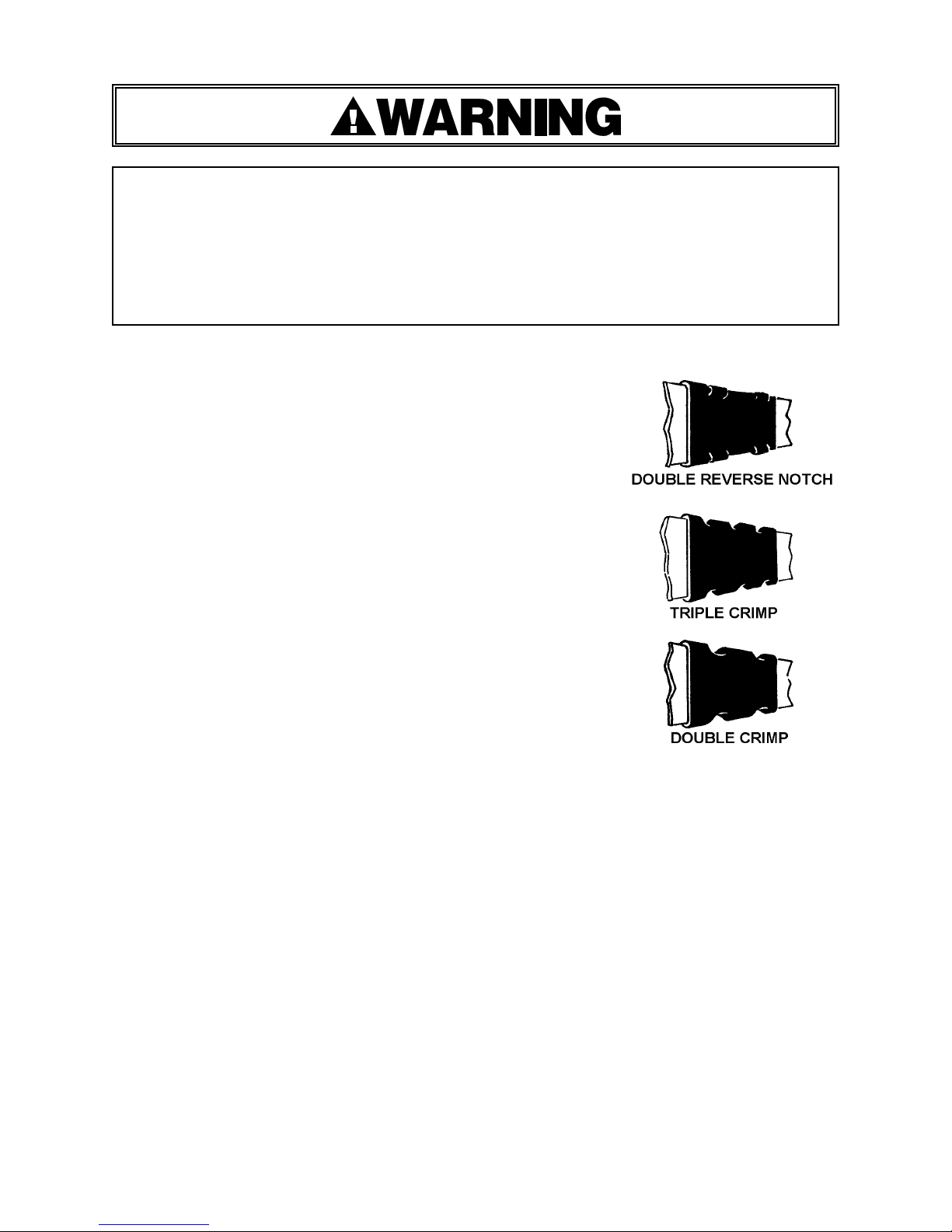
2. The RCN-3435 and the RCN-1435 are double reverse notch
sealers. The N-1435, N-1444-50LSH and N-1457LSH are double
crimp sealers and the NS-1457-75L and the NS-250-65L are single
crimp sealers, although the single crimp sealers are usually
required to place two crimps per seal. If an NS-250-65L tool is
being used to crimp a 203 seal, then three crimps per seal are
required. Refer to the specifications at the back of this manual
for details. Properly notched or crimped seals will appear as
shown in the illustration. If the joint does not appear as shown,
then the operator must proceed as follows:
A. Ensure that the tool's operating instructions are being
followed before applying another strap.
B. Cut the strap off and apply another.
3. An improperly formed seal which does not have good notches or
crimps, could result in strap separation. Before moving any
package be certain that the seal is formed as shown. Inspect the
joint to make certain it appears as shown in the illustration. If
not, remove the strap and check the tool for worn or broken
parts. Repair the tool before applying another strap.
MOVING AND STACKING STRAPPED LOADS
Before moving or stacking any strapped load, follow all standard industry practices regarding safe
material handling procedures.
CUTTING TENSIONED STRAP
Using claw hammers, crowbars, chisels, axes or similar tools will cause tensioned strap to fly
apart with hazardous force. Use only cutters designed for cutting strap. Read the instructions in
the cutters manual for proper procedure in cutting strap. Before using any Signode product read
its Operation and Safety Manual.
TOOL CLEANING & LUBRICATION
Clean and apply a light weight machine oil to all moving parts on a weekly basis. Refer to the
Pneumatic Information shown in this manual for lubricant recommendations with regard to tool
operation.
3
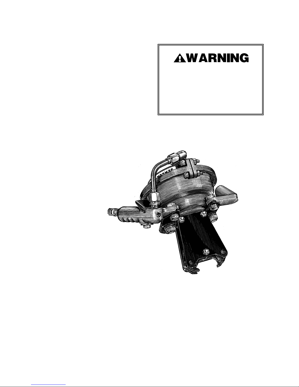
TABLE OF CONTENTS
General Safety Information 2
Tool Installation 4
Specifications 5
Pneumatic Information 6
Operating Instructions 9
Joint Formation 10
Parts List & Exploded Views 11
Declaration of Conformity 19
RCN-3435
Part No. 009030
RCN-1435
Part No. 008500
Page
Signode tools and machines are designed
and warranted to work together with
Signode strapping and seals. Use of nonSignode strap, seals and/or manufactured
or specified replacement parts may result
in strap breakage or joint separation
while applying strapping to a load or
during
N-1435
Part No. 008505
N-1444-50LSH
Part No. 024271
N-1457LSH
Part No. 183022 (0X1015)
NS-1457-75L
Part No. 014390
NS-250-65L
Part No. 014360
TOOL INSTALLATION
To work effectively, these sealers must be properly installed. This installation includes, in some
cases, proper suspension of the tool over the container to be strapped and the proper placement
of the strapping dispenser to provide a continuous easy supply of strapping for the application.
The sealers may be suspended for sealing on top of a package by means of an optional eye bolt
(35A) located on top of the tool. If desired, the sealers can be suspended for sealing on the side of
a package by attaching a bracket (Part No. 010749) which can be obtained on request.
4

SEALER SPECIFICATIONS
SEALS
TOOLS STRAP SIZE
RCN-3435
Double Reverse
Notch
RCN-1435
Double Reverse
Notch
N-1435
Double Crimp
N-1444-50LSH
DoubleCrimp
3/4 x .025-.031 Painted & Waxed Magnus
1-1/4 x .031 Painted & Waxed Magnus
1-1/4 x .035 Painted & Waxed Heavy duty
1-1/4 x .031 Waxed Zinc finish Magnus
1-1/4 x .031 Dry Magnus 127
1-1/4 x .031 Painted & Waxed Magnus
1-1/4 x .031 Waxed Zinc finish Magnus
1-1/4 x .035 Painted & Waxed heavy duty
1-1/4 x .035 Painted Only, heavy duty
1-1/4 x .044 Dry Magnus
1-1/4 x .044 Painted U.S.G.M. Magnus
1-1/4 x .031 Painted & Waxed Magnus
1-1/4 x .044 Painted U.S.G.M. Magnus
1-1/4 x .050 Painted & Waxed U.S.G.M.
Magnus
REQUIRED
(PER
JOINT)
34HC
34HOC
34HC-OF
114
114OF
114P
107DG
107DGOF
117HDGOF 2 80 psig
117HDGOF 3
1 55 psig
1 65 psig
2 70 psig
*MIN. AIR
PRESSUR
ETYPE
80 psig
90 psig
N-1457LSH
Double Crimp
NS-1457-75L
Single Crimp
NS-250-65L
Single Crimp
* For fast and positive sealing, maintain an air line supply pressure at least 10 psig higher than the
minimum air pressure required to seal.
** Requires two seals with two crimps per seal.
*** Three crimps per seal required for packaging applications only.
1-1/4 x .057 Painted & Waxed U.S.G.M.
Magnus 117HDGOF 3 90 psig
1-1/4 x .057 Zinc Finish Magnus
114HL** 1
1-1/4 x .075 Zinc Finish Magnus 90 psig
2 x .044 Painted & Waxed Magnus
2 x .044 Painted Magnus
2 x .050 Painted Heavy Duty
208DG
1 80 psig2 x .044 Dry Finish Magnus 208
208DG
203***
65 psig
5
PNEUMATIC INFORMATION
Air Supply Installation
If the compressor has a good dryer unit, use black pickled pipe. When a dryer unit is not installed,
use galvanized or copper pipe.
To preform reliably, a pneumatic tool requires a continuous source of clean, water-free air at
adequate pressure.
Never operate this tool using a bottled air or gas source.
Bottled air/gas sources do not provide consistent operating pressure and
could result in air pressures that exceed the maximum allowed for the tool.
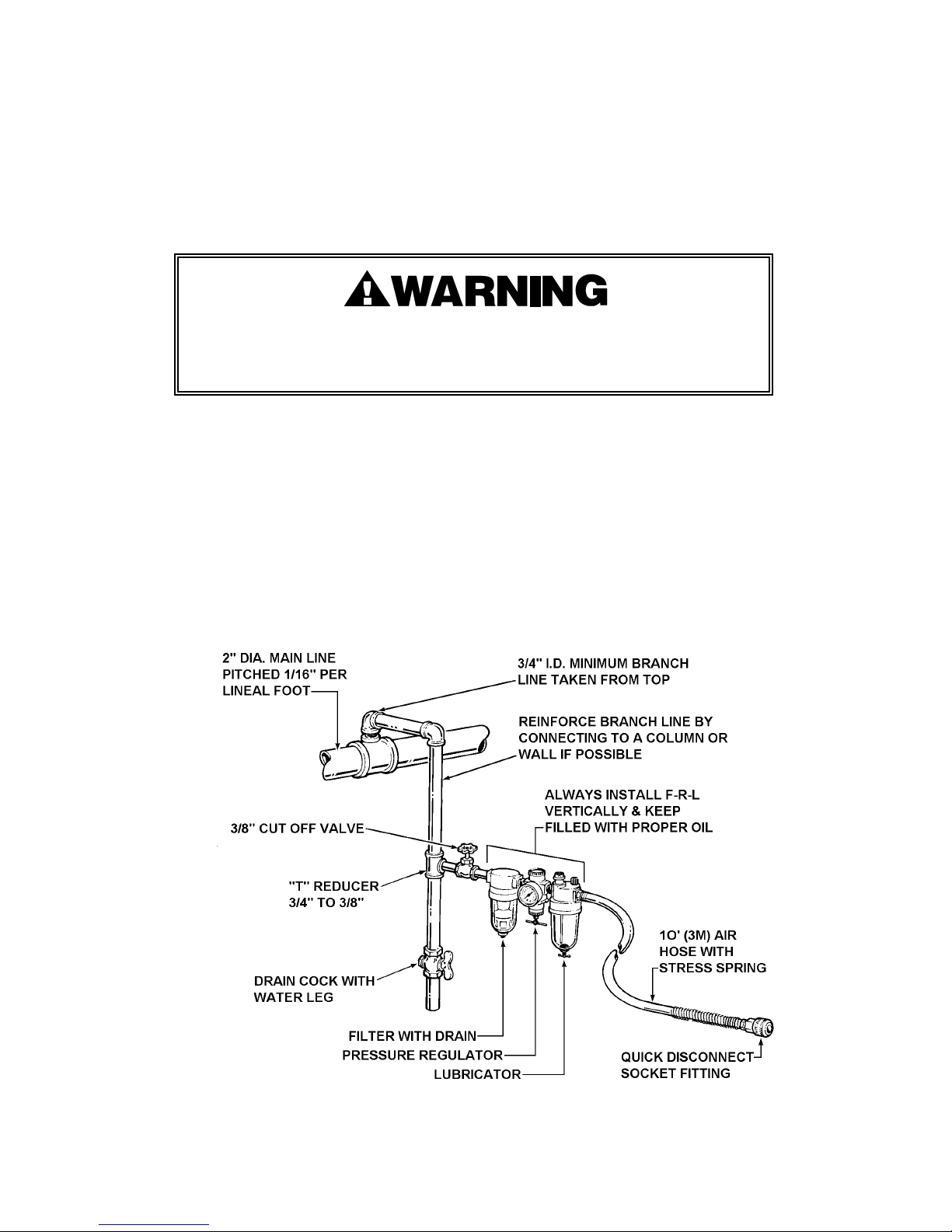
A filter-regulated-lubricator unit (Signode Part No. 008559) must be installed as close to the air tool
as possible, preferably within 10 feet. It should be placed in a convenient location where it can
easily be drained, adjusted, and filled with oil. The air hose must have at least a 3/8" I.D.. A quickconnect press-on socket is installed on the stress spring end of the hose for convenient hookup to
the air tool.
Filter and lubricator bowls are made of polycarbonate material. Do not install where bowls may be
exposed to materials incompatible with poly carbonate. Certain oils, solvents, and chemicals or
their fumes can weaken these bowls and possibly cause them to burst. Clean only with warm
water. A cut-off valve placed ahead of the filter will be useful when cleaning the filter or
replenishing the lubricator.
6

MOISTURE
Moisture is always present in air lines due to condensation within the lines as the air cools. Steps
must be taken to remove this moisture and to keep it from the air tool. This is because water tends
to wash away lubricants and cause corrosion, sticking and failure of internal parts.
The main line should be pitched so the far end terminates in a water leg. Branch lines are taken
from the top of the main, never off the bottom. Every branch should have a water leg at its lowest
point, with a drain cock which is drained daily.
If these precautions are taken and water is still present, an after cooler and a moisture separator
are required between the compressor and the air receiver tank. A large air line separator can be
installed in the air tool line, but precautions must be taken to insure that it will be drained daily,
before the air tool is operated.
Water in air lines is a constant threat to the proper operation of air tools. Even near freezing
operating conditions, a good refrigerant type dryer is essential. A good dryer will remove 95% or
more of water right at the compressor. The remaining moisture is removed at the water leg in the
piping system or in the filter (Part No. 173111).
NOTE: Additional information is available in the Signode publication, "Air Supply Manual" (Part No.
186038). If you have any questions, contact your local Signode Representative.
LUBRICATION
The air motor must be properly lubricated. This is achieved by keeping the air line lubricator filled
with oil and correctly adjusted. Without proper lubrication, the motor will become sticky and the
tool will give low and erratic tension and be difficult to release from the strap.
Install the lubricator as close to the air tool as possible. The arrow on the lubricator's top surface
must point in the direction of air flow. For proper operation, oil must drop through the lubricator
sight glass at a rate of 1 to 4 drops per minute. This rate is checked while the air tool is running
free. Only 20% of this oil is actually delivered to the tool. The remaining oil drops back into the oil
reservoir. The unit is factory set and should require no adjustment. If an adjustment is required,
the adjusting screw on top of the lubricator may be turned as marked to reduce or increase the
flow of oil.
The correct grade of oil must be used in the lubricator; too heavy an oil will not provide sufficient
lubrication and will cause sticking and sluggish operation of the air tool. Recommended oils are
any good grade of rust and oxidation inhibiting oil with a viscosity of 80-120 S.U.S. at 100 degrees
Fahrenheit. (0.15 to 0.25 cm
2
/sec. at 38 degrees Celsius), such as:
Non Fluid Oil Co., grade #LS-1236 Signode oil - Part No. 008556
If necessary, use SAE #5 or SAE #10 non-detergent, cut 1 to 1 with kerosene.
NOTE: Some oils contain anti-wear additives which may disable the air motor. Be certain to use
recommended oil.
Several drops of lubricator oil added to the inlet of the air motor or into the air line each day will
help insure good operation. A noticeable reduction of air motor performance can usually be
corrected by squirting a few drops of oil into the air line.
7

PNEUMATIC INFORMATION, Continued
COLD WEATHER OPERATION
If a tool does not operate satisfactorily in freezing temperatures, certain steps can correct the
problem. The following steps can be taken to improve cold weather operation of the tool:
a. An air line dryer adjacent to the compressor.
b. Use lubricant recommended by Signode. Signode has tested the use of anti-freezes, none
work well in air tools; the tool will gum up when anti-freezes are introduced and will not
function properly. The best lubricant for freezing weather is the 1 to 1 oil and kerosene
combination.
c. If possible, run the air supply line to a indoor located Filter-Regulator-Lubricator or relocate the
F-L-R to a warmer operating area.
AIR PRESSURE REQUIREMENTS
Maximum operating air pressure is 130 psig.
Air line pressures must be maintained within the specified range.
A minimum air pressure setting, as indicated in the Specifications Section, must be maintained to
ensure that the tool will seal properly.
8

OPERATING INSTRUCTIONS
Wear safety glasses which conform to ANSI Standard Z87.1 or EN 166.
Stand to one side of the strap while tensioning.
Make sure all bystanders are clear before proceeding.
Failure to follow the above could result in severe personal injury.
All sealers are compact, well balanced tools which combine the advantages of easy sealing action
with high, uniform joint strength. Their simplicity of design assures continuous service without
mechanical adjustment or maintenance. When used with air pressure at the high side of the range,
the sealing is practically instantaneous. When the pressure is on the low end of the range, care
should be taken to make sure that the sealing stroke is completed before releasing the pressure
valve. This can be determined by the click sound made as the stroke is completed.
SPECIAL INSTRUCTIONS FOR N-1444-50LSH
This model has a unique feature which helps prevent
incomplete notching or crimping of the seal and strapping.
When the air line supply pressure drops below the 70 psig
minimum sealing pressure, the jaw mechanism will lock on
the joint until the air pressure is increased. A manual
release is provided to unlock the jaw mechanism. To
unlock the sealing mechanism, insert a screwdriver into
the slot on the locking link (55) and pry outward, using the
side plate for leverage, until jaws release.
SEALING OPERATION
Sealing is performed by positioning the
sealer jaws on the seal in the desired
location, then pressing the black thumb lever
located on the right handle grip. The lever
must be kept completely depressed until
crimping action is completed. This is
indicated by an audible click.
9

JOINT FORMATION
The RCN-3435 and the RCN-1435 are double reverse notch sealers.
The N-1435, N-1444-50LSH and N-1457LSH are double crimp sealers
and the NS-1457-75L and the NS-250-65L are single crimp sealers,
although the single crimp sealers are usually required to place two
crimps per seal. If an NS-250-65L tool is being used to crimp a 203
seal, then three crimps per seal are required. Refer to the
specifications at the back of this manual for details. Properly
notched or crimped seals will appear as shown in the illustration. If
the joint does not appear as shown, then the operator must proceed
as follows:
A. Ensure that the tool's operating instructions are being followed
before
applying another strap.
B. Cut the strap off and apply another.
An improperly formed seal which does not have good notches or
crimps, could result in strap separation. Before moving any
package be certain that the seal is formed as shown. Inspect the
joint to make certain it appears as shown in the illustration. If not,
remove the strap and check the tool for worn or broken parts.
Repair the tool before applying another strap.
NEVER HANDLE OR SHIP ANY LOAD WITH IMPROPERLY FORMED JOINTS. Misformed
joints may not secure the load and could cause serious injury. Follow the joint inspection
procedures in each sealers’s manual.
MAINTENANCE INSTRUCTIONS
Wear safety glasses which conform to ANSI Standard Z87.1 or EN 166.
Make sure the air has been disconnected from the tool before proceeding.
Use care when working with the compression spring (25).
Closely inspect the tool and replace any parts that are found to be broken.
Periodic cleaning of all external moving parts and the application of a light machine oil will greatly
prolong the serviceability of these tools. In applications where a lubricator is not used, periodic
addition of a light machine oil added directly to the hose connection is recommended. The sealers,
if functioning properly, will not leak air when the control lever is in the “off” position or when
holding the control lever firmly in the “on” position. If leakage is present, the Diaphragm (33)
should be examined for damage or extreme wear. Remove the clamp ring (31) and separate the
pressure plate (34) from the non-pressure plate (27). Remove the diaphragm, and replace if
necessary.
10

PARTS LIST
N-1444 N-1457 NS-1457 NS-250
KEY
1 1 008465 008465 008465 008465 008465 008465 008465 Valve cap
2 2 008134 008134 008134 008134 008134 008134 008134 "O" ring
3 1 008462 008462 008462 008462 008462 008462 008462 Spring
4 1 008468 008468 008468 008468 008468 008468 008468 Valve extension
5 2 008469
6 2 008494 008494 008494 008494 008494 008494 008494 Spacer
7 1 008468 008468 008468 008468 008468 008468 008468 Valve stem
8 1 008463 008463 008463 008463 008463 008463 008463 Stem cap
9 1 008477 008477 008477 008477 008477 008477 008477 SH Pipe plug, 1/4 NPT
10 1 008474 008474 008474 008474 008474 008474 008474 Rd. slot hd. mach.
11 1 008466 008466 008466 008466 008466 008466 008466 Control lever
12 1 004963 004963 004963 004963 004863 004963 004963 Flexloc nut, thin 10-32
13 2 008493 008493 008493 008493 008493 008493 008493 Hex nut, 5/8-18
14 2 008496 008496 008496 008496 008496 008496 008496 Lock washer, 5/8
15 1 008470 008510 008476 030271 030271 014399 008470 Mounting plate
16 2 008497 008497 008497 008497 008497 008497 008497 HHCS 9/16-12x1-1/4
17 1 008473 008473 008473 008473 008473 008473 008473 Left handle
18 2 003449 003449 003449 003449 003449 003449 003449 Washer, 5/8 SAE
19 2 008499 008499 008499 008499 008499 008499 008499 Lock washer, 9/16
20 2 008498 008498 008498 008498 008498 008498 008498 Jam nut, 9/16-12
21 1 008482 008482 008482 008482 008482 008482 008482 Connector
22 1 008480
23 1 008483 008483 008483 008483 008483 008483 008483 Elbow, 90 degree
24 1 009033 008459 008459 014361 014361 014361 014361 Ram
25 1 014366 014366 014366 014366 014366 014366 014366 Spring
26 1 008488 008488 008488 014363 014363 014363 014363 Push plate
27 1 008484 008484 008484 014362 014362 014362 014362 Non-pressure plate
30 2 008492 008492 008492 008492 008492 008492 008492 Hex nut, 5/16-24
31 1 008487 008487 008487 014367 014367 014367 014367 Clamp ring
32 2 008491 008491 008491 008491 008491 008491 008491 Bolt**
33 1 008486 008486 008486 014365 014365 014365 014365 Diaphragm
34 1 008485 008485 008485 014364 014364 014364 014364 Pressure plate
35 1 008477 008477 008477 008477 008477 008477 008477 Pipe plug, 1/4-18
35A 1 009025 009025 009025 009025 009025 009025 009025 Eye bolt (optional)
36 3 008512 -- -- -- -- -- 008512 SHCS 3/8-24 x 2
36A 3 -- -- 008513 008513 008513 -- -- SHCS 3/8-24 x 3
36B 3 -- 006827 -- -- -- 006827 -- SHCS 3/8-24 x 2 1/4
37 1 -- -- 008479 161366 161366 -- -- Stop spacer
38 2 009036
39 2 009029 008458 008458 008458 008458 014395 008458 Spacer
40 2 -- -- 014381
41 2 009028 008506 008514 008514 008514 014396 008455 Jaw pin
42 2 009026
43 1 009027 008508 008515 008515 008515 014398 008557 Ram pin
44 4 -- -- 008518 008518 008518 014393 008453 Link
45 2 -- -- 008495 008495 008495 -- -- Link spacer
46 4 -- -- 008472 008472 008472 -- -- Retaining ring
47 2 009035
48 3 003868 003868 003868 003868 003868 003868 003868 Flexloc nut, thin 3/8-24
QTY. RCN-3435 RCN-1435 N-1435 50LSH LSH 75L 65L DESCRIPTION
008469 008469 008469 008469 008469 008469 Seal
scr., 10-32 x 1 3/4
x 3/8
008480 008480 014368 014368 014369 014368 Tubing assembly
1/2 tube to 1/4 pipe
008501 -- -- -- -- -- Link
031297 031297 014391 008451 Jaw
008507 008516 008516 008516 014397 008456 Link pin
008502 014383 030270 030270 014394 008454 Side plate
11

PARTS LIST, Continued
N-1444 N-1457 NS-1457 NS-250
KEY
49*** 2 -- -- 014371 031296 031296*** -- -- Crimper
50 1 009032
51 4 009031 008511 -- -- -- -- -- Jaw
52 1 -- -- -- -- -- 014392 008452 Crimper
53 1 -- -- -- 017949 017949 -- -- Link retainer
54 1 -- -- -- 030263 030263 -- -- Guide spacer
55 1 -- -- -- 030264 030264 -- -- Locking link
56 1 -- -- -- 030265 030265 -- -- Link spacer
57 1 -- -- -- 030267 030267 -- -- Spring
58 1 -- -- -- 007631 007631 -- -- Roll pin, 1/8 x 3/8
59 1 003132 003132 003132 003132 286305 003132 003132 Caution sign
60 1 008673 008673 008673 008673 286303 008673 008673 Nameplate
* Handle, complete with valve, Part No. 008460, includes keys 1 through 12.
** For field replacement use Soc. hd. cap scr., 5/16-24 x 1 1/2, Part No. 008851.
*** Use (2) crimpers (Part No. 183023) when using .057" U.S.L.M. Magnus strapping.
C
C
C
QTY. RCN-3435 RCN-1435 N-1435 50LSH LSH 75L 65L DESCRIPTION
008503 -- -- -- -- -- Notcher
When ordering parts please show tool model, part number and name.
All recommended spare parts are underlined and should be stocked.
Standard hardware parts may be obtained from local hardware suppliers.
Items furnished with each sealer: 3/8" air hose (10' long) - Part No. 008558
Disconnect plug - Part No. 008568
Disconnect socket - Part No. 008569
NOTE: Special manufacture sealer N-1457LSH is the same as the N-1444-50LSH sealer except for the special crimpers
(Part No. 183023) which must be used when using .057" U.S.L.M. Magnus strapping.
NOTE: Snug hex nut (30) prior to
torquing. Tap periphery and torque to
75-90 inch pounds.
12

13

14

15

16

17

18

EU Declaration of Conformity
The Supply of Machinery (safety) Regulations
1992 (S.I. 1992/3073)
It is hereby declared that the undermentioned machinery has been designed and
constructed to comply with the health and safety requirements defined in EC
Directive 89/392/EEC
Machine Supplier: Signode, Division of ITW Ltd.
Queensway, Fforestfach
Swansea SA5 4ED
Machine Description: RCN Tool Series
N Tool Series
NS Tool Series
Machine Type: Pneumatic Sealer Hand Strapping tool.
Provisions with which machine complies:
89/392/EEC, 91/368/EEC
Harmonized EuroNorms with which machine complies:
EN 292:1, EN 292:2, EN 294, EN 349
Technical Standards with which machine complies:
NA
Signature: Date: 19 DEC 1994
Peter Oseland)
(
19

SIGNODE
NEW TOOL WARRANTY
Signode Engineered Products Warrants that a new Signode strapping tool will operate per functional
specifications for a period of sixty (60) days after the date of shipment to the owner's place of business.
Normal wearing parts, as outlined in the Operation, Parts & Safety manual, are covered by a thirty (30) day
warranty unless, in Signode's judgement, these parts have been subjected to abnormal or extreme usage.
Signode's sole liability hereunder will be to repair or replace, without charge, F.O.B. Signode's Glenview,
Illinois plant, any tool which proves to not operate per functional specifications within the stated period.
Signode reserves the right to replace any tool which proves not to operate per functional specifications
with a new or like-new tool of the same model if in Signode's judgement such replacement is appropriate.
Any new replacement tool provided to an owner will carry a full sixty (60) day warranty. Any warranty
repaired tool or like-new replacement tool will carry a warranty for the balance of the time remaining on the
initial sixty (60) day warranty. This warranty will be extended to compensate for the time the tool is in
Signode's possession for warranty repairs.
This warranty is void as to any tool which has been: (I) subjected to mis-use, misapplication, accident,
damage, or repaired with other than genuine Signode replacement parts, (II) improperly maintained, or
adjusted, or damaged in transit or handling; (III) used with improperly filtered, unlubricated air or improper
strapping material, (IV) in Signode's opinion, altered or repaired in a way that affects or detracts from the
performance of the tool.
SIGNODE MAKES NO WARRANTY, EXPRESSED OR IMPLIED, RELATING TO MERCHANTABILITY,
FITNESS OR OTHERWISE EXCEPT AS STATED ABOVE AND SIGNODE'S LIABILITY AS ASSUMED ABOVE
IS IN LIEU OF ALL OTHERS ARISING OUT OF OR IN CONNECTION WITH THE USE AND PERFORMANCE
OF THE TOOL. IT IS EXPRESSLY UNDERSTOOD THAT SIGNODE SHALL IN NO EVENT BE LIABLE FOR
ANY INDIRECT OR CONSEQUENTIAL DAMAGES INCLUDING, BUT NOT LIMITED TO, DAMAGES WHICH
MAY ARISE FROM LOSS OF ANTICIPATED PROFITS OR PRODUCTION, SPOILAGE OF MATERIALS,
INCREASED COSTS OF OPERATION OR OTHERWISE.
Considerable effort has be made to ensure that this product conforms to our high quality standards.
However, should you experience any difficulties, please contact your Sales Representative providing
samples and the manufacturing code specified on the tool.
Thank you for your help.
SIGNODE ENGINEERED PRODUCTS
Hand Tool Division
3620 W. Lake Avenue, Glenview, Illinois 60025
© Copyright 2000, Signode 186062 Rev. 10/2000
 Loading...