

Page 1

07.09
OPERATION, PARTS AND
SAFETY MANUAL
MANUAL DE OPERACIÓN, PARTES
Y SEGURIDAD
BXT2
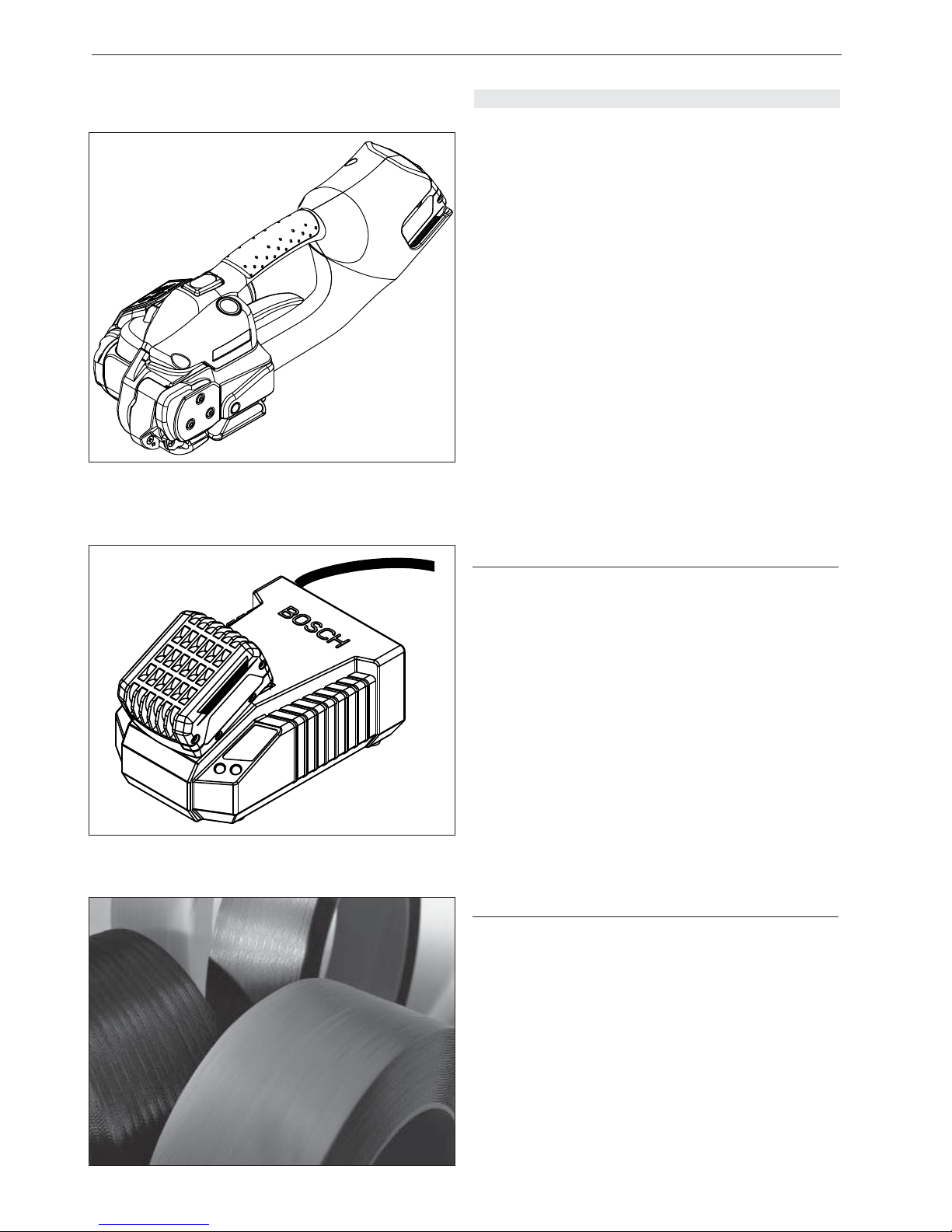
BATTERY-HAND TOOL FOR PLASTIC STRAPPING
APARATO PORTÁTIL CON ACUMULADOR PARA
FLEJADO CON CINTA PLÁSTICA
IMPORTANT!
DO NOT DESTROY
It is the customer’s responsibility to
have all operators and servicemen
read and understand this manual.
Contact your local Signode representative for additional copies of this manual.
READ ALL INSTRUCTIONS BEFORE OPERATING THIS SIGNODE PRODUCT
LEA CUIDADOSAMENTE ESTE INSTRUCTIVO ANTES DE UTILIZAR EL APARATO
SIGNODE • 3610 W. LAKE AVENUE • GLENVIEW, ILLINOIS 60025 U.S.A.
Page 2

2
07.09
SHORT INSTRUCTIONS
+
1st charge > 5 hr / Recharging approx. 20–40 min.
1. cargar > 5 hr / Recargar aprox. 20–40 min.
1. Laden > 5 Std. / Aufl aden ca. 20–40 min.
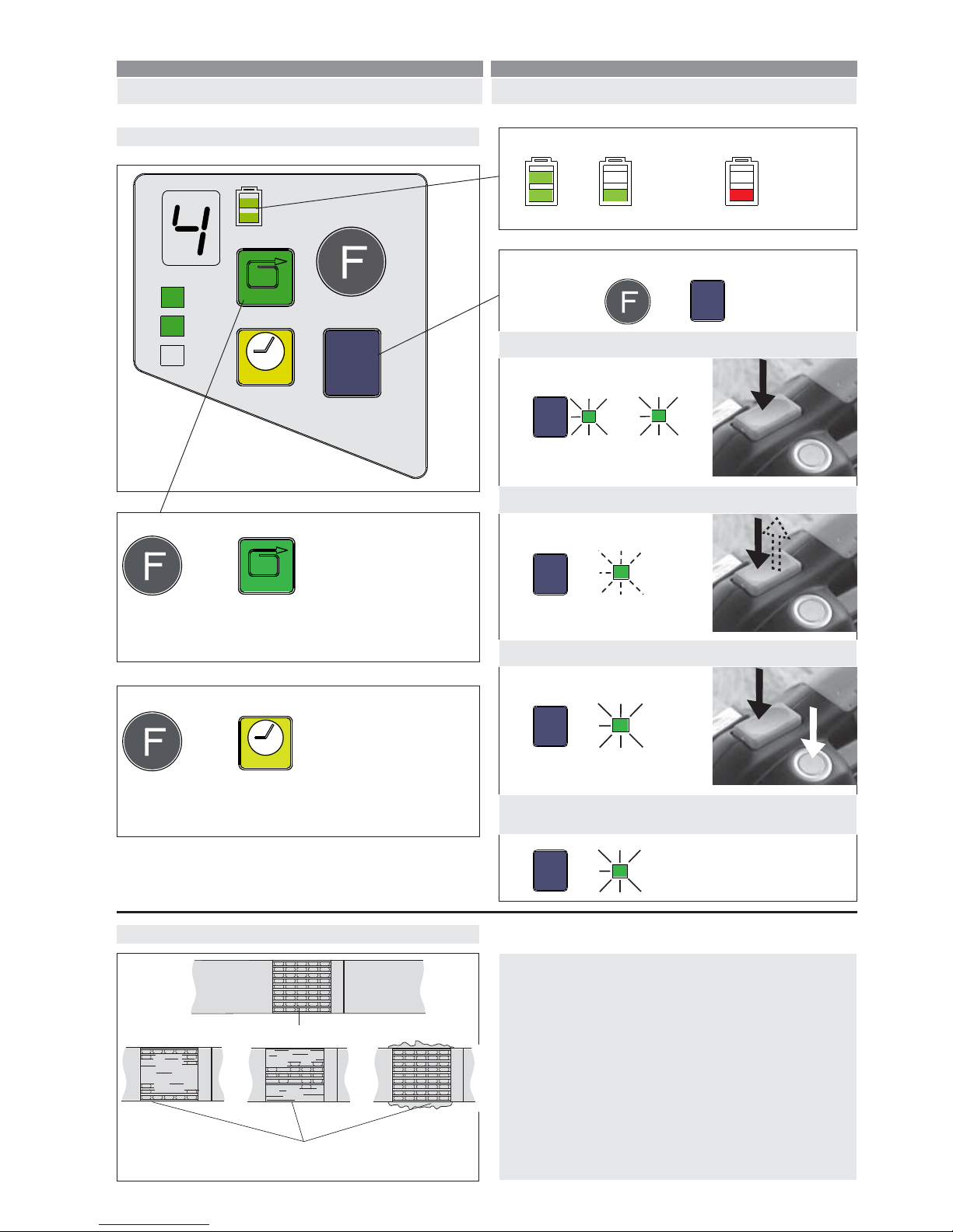
Mode of operation: / Modo operativo: / Betriebsart:
Semi-Auto / Semiautomático / Halbautomatisch
The most important points in brief!
Operation / Operación / Bedienung
Charging battery / Cargar acumulador / Akku laden
➟Tensioning / Tensado / Spannen
➟Welding / Soldadura / Schweissen
2.
3.
4.
1. 3.
2.
green / verde / grün
red / rojo / rot
Error / Defecto / Fehler
AUT
O
MAN.
+
Insert battery / Inserte acumulador / Akku einsetzen
✓
Tool is switched on
Aparato conectado
Gerät ist eingeschaltet
1.
Page 3
3
07.09
KURZANLEITUNG
Das Wichtigste in Kürze!
Mode of operation / Modo operativo / Betriebsart
Semi-Auto / Semiautomático / Halbautomatisch:
Manual / Manual / Manuell:
Fully-Auto / Automático / Vollautomatisch:
AUT
O
MAN.
AUTO
MAN.
SOFT
AUTO
MAN.
SOFT
AUTO
MAN.
SOFT
fl ashing / intermitente /
blinkend
Operating panel / Panel del operación / Bedienpanel
AUTO
MAN.
SOFT
AUTO
MAN.
SOFT
+ / -
+ / -
Checking seal / Inspección / Kontrolle
Good seal / Buena soldadura / Gute Schweissung
Poorly welded seal / Soldadura defectuosa /
Schlechte Schweissung
For detailed description,
see operating instructions from page 4!
Observe descripción detallada,
en el instructivo de operación, página 4!
Für detaillierte Beschreibung,
siehe Betriebsanleitung ab Seite 4!
Battery charge / Carga de la batería / Akku-Ladezustand
Welding time / Tiempo de soldadura / Schweisszeit
LED Display / Indicatores LED / LED Anzeige:
1 = min.
7 = max.
+ / -
AUTO
MAN.
SOFT
+ / -
Tension force / Tensión / Spannkraft
LED Display / Indicatores LED / LED Anzeige:
1 = ca. 900 N (200 lbs.) Soft / Suave 400 N (88 lbs.)
9 = ca. 2500 N (560 lbs.) Soft / Suave 1500 N (335 lbs.)
➟
➟
➟
➟
➟
➟
✓
➟ Recharge
➟ Recargar
➟ Aufl aden
1.
2.
=
=
=
MAN.
+
AUT
O
green / verde / grün
red / rojo / rot
✓
Soft tension / Tensión suave / Softspannung:
(PP straps / Cintas PP / PP Band)
AUTO
MAN.
SOFT
➟
SOF
T
For soft packages
Para los paquetes suaves
Für weiche Packgüter
=
INSTRUCCIÓNES BÁSICAS
¡La mayoría de los aspectos!
Page 4
4
07.09
SIGNODE BXT2
TABLE OF CONTENTS
Page
SHORT INSTRUCTIONS 2
1 T echnical data 4
2 General information 8
2.1 Information on environmental protection 8
3 Safety instructions 10
4 Description 12
4.1 Construction 12
4.2 Operating panel 12
4.3 Function 12
5 Operating instructions 14
5.1 Charging the battery 14
5.2 Operating the tool 14
5.3 Checking the seal 18
5.4 Checking battery charge 18
5.5 Setting mode of operation 18
5.6 Setting strap tension 20
5.7 Setting soft tension 20
5.8 Setting welding time 20
5.9 Setting strap width 20
6 Special functions 22
6.1 Switch touch-pad lock on and off 22
6.2 Sleep mode 22
6.3 T ool reset 22
7 Preventive and corrective maintenance 24
7.1 Cleaning/replacing tension wheel 24
7.2 Cleaning/replacing tooth plate 24
7.3 Replacing knife 24
7.4 Trouble shooting 26
8 Wear parts / Recommended spare parts 28
8.1 Parts list 28
Exploded drawing 32
DECLARATION OF CONFORMITY
www.signode.com
We take sole responsibility for declaring that the tool
BXT2 to which this declaration refers is in full conformi ty with the current requirements of the guidelines laid
down by the council on 22th June 1998 (98/37/ECC),
“Machine Guidelines“.
Furthermore, electrical installations are in conformity
with the guideline laid down by the council on 12.
December 2006 (2006/95/EEC) “Low Voltage Guide lines“ and 15. December 2004 (2004/108/EEC)
“EMV Guidelines“.
Harmonised standards applied:
EN ISO 12100-1, EN ISO 12100-2, EN 349,
EN 1050, EN 61000-6-1, EN 61000-6-3
15.11.2008
General Manager General Manager Prod.
Packaging Technology: Packaging Technology:
U. Schweizer M. Binder
SIGNODE ENGINEERED PRODUCTS
Hand Tool Division
3610 W. Lake Avenue,
Glenview, Illonois 60025
Page 5
5
07.09
SIGNODE BXT2
INHALTSVERZEICHNIS
Seite
KURZANLEITUNG 2
1 T echnische Daten 5
2 Allgemeines 9
2.1 Hinweise zum Umweltschutz 9
3 Sicherheitsvorschriften 11
4 Beschreibung 13
4.1 Aufbau 13
4.2 Bedienpanel 13
4.3 Funktionsprinzip 13
5 Bedienung 15
5.1 Akku aufl aden 15
5.2 Bedienung des Gerätes 15
5.3 Verschlusskontrolle 19
5.4 Akku-Ladezustand prüfen 19
5.5 Betriebsarten einstellen 19
5.6 Spannkraft einstellen 21
5.7 Softspannung einstellen 21
5.8 Schweisszeit einstellen 21
5.9 Bandbreite einstellen 21
6 Sonderfunktionen 23
6.1 Tastensperre ein- und ausschalten 23
6.2 Schlafmodus 23
6.3 Geräte-Reset 23
7 Wartung und Instandsetzung 25
7.1 Spannrad reinigen/ersetzen 25
7.2 Zahnplatte reinigen/ersetzen 25
7.3 Messer ersetzen 25
7.4 Beheben von Störungen 27
8 Verschleissteile / Empfohlene Ersatzteile 28
8.1 T eileliste 28
Explosionszeichnung 32
CONTENIDO
Página
INSTRUCCIÓNES BÁSICAS 2
1 Información técnica 5
2 Generalidades 9
2.1 Indicaciones ecológicas 9
3 Disposiciones de seguridad 11
4 Descripción 13
4.1 Construcción 13
4.2 Panel de operación 13
4.3 Principio de operación 13
5 Operación 15
5.1 Cargado del acumulador 15
5.2 Operación del aparato 15
5.3 Inspección de soldadura 19
5.4 Comprobar carga del acumulador 19
5.5 Ajustar modos de operación 19
5.6 Ajuste de grado de tensado 21
5.7 Ajustar tensión suave 21
5.8 Ajuste del tiempo de soldadura 21
5.9 Ajuste del ancho de la cinta 21
6 Funciones especiales 23
6.1 Bloqueo y desbloqueo del teclado 23
6.2 Modo en guardia durmiente 23
6.3 Restablecer equipo 23
7 Mantenimiento y servicio 25
7.1 Limpieza y reemplazo de la rueda tensora 25
7.2 Limpieza y reemplazo de la placa dentada 25
7.3 Reemplazo de la cuchilla cortadora 25
7.4 Eliminación de averías 27
8 Partes desgastables / Recambios recomend. 28
8.1 Listado de partes 28
Diagrama de explosión 32
KONFORMITÄTSERKLÄRUNG
Wir erklären in alleiniger Verantwortung, dass das
Gerät BXT2, auf welches sich diese Erklärung bezieht,
mit den geltenden Bestimmungen der Richtlinie des
Rates vom 22. Juni 1998 (98/37/EG) „Maschinen Richtlinie“ und deren Änderungen übereinstimmt.
Im weiteren gilt die Übereinstimmung mit den geltenden
Bestimmungen der Richtlinie des Rates vom 12.
Dezember 2006 (2006/95/EG) „Niederspannungs Richtlinie“ und vom 15. Dezember 2004 (2004/108/EG)
„EMV-Richtlinie“.
Berücksichtigte Normen:
EN ISO 12100-1, EN ISO 12100-2, EN 349,
EN 1050, EN 61000-6-1, EN 61000-6-3
15.11.2008
General Manager General Manager Products
Packaging Technology: Packaging Technology:
U. Schweizer M. Binder
DECLARACIÓN DE CONFORMIDAD
Los abajo fi rmantes declaramos, asumiendo nuestra
sola responsabilidad, que el equipo al que se refi ere
esta declaración corresponde a los lineamientos técni cos vigentes, establecidos por el consejo del 22 de
junio de 1998 (98/37/EG) „Lineamientos de maquina ria“.
Por lo demás tiene validez la conformidad con las
disposiciones vigentes establecidas los lineamientos
concejales de 12. diciembre 2006 (2006/95/EG) „Nie
derspannungs-Richtlinie“ und vom 15. Dezember 2004
(2004/108/EG) „EMV-Richtlinie“.
Normas contempladas:
EN ISO 12100-1, EN ISO 12100-2, EN 349,
EN 1050, EN 61000-6-1, EN 61000-6-3
15.11.2008
General Manager General Manager Products
Packaging Technology: Packaging Technology:
U. Schweizer M. Binder
Page 6
6
07.09
SIGNODE BXT2
1 TECHNICAL DATA
Weight 3.9 kg (8.6 lbs.)
(incl. battery)
Dimensions Length 370 mm (14.5“)
Width 138 mm (5.4“)
Height 148 mm (5.8“)
Strap tension (0) 900–2500 N (200–560 lbs.)
Soft: 400–1500 N (88–335 lbs.)
Tension speed 220 mm/s (8.6“/s)
Sealing Friction weld
Emission sound pressure
levels, measurement
type A (EN ISO 11202) L
pA
82 dB (A)
Vibrations at handle
(EN ISO 8662-1) a
h,w
2.2 ms
-2
BATTERY CHARGER / BATTERY
Battery charger voltage 100 / 110 / 230 V
Battery charger type BOSCH AL 1860 CV
Charging time 20–45 minutes,
after 20 min approx. 70%
charging capacity
Strappings with
one battery charge 200 to 400 depending on
strap, strap tension and
package
Battery 14.4 V / 2.6 Ah, Li-Ion
BOSCH
PLASTIC STRAP
Strap quality Polypropylene (PP)
Polyester (PET)
Strap width
adjustable to 12–13, 15–16 mm
(
1
/2“, 5/8“)
(option: 9–11 mm)
(
3
/8“)
Strap thickness 0.5–1.0 mm
(.019“–.040“)
Page 7

7
07.09
SIGNODE BXT2
Gewicht 3,9 kg (inkl. Akku)
Abmessungen Länge 370 mm
Breite 138 mm
Höhe 148 mm
Spannkraft (0) 900–2500 N
Soft: 400–1500 N
Spanngeschwindigkeit 220 mm/s
Verschluss Reibschweissverschluss
Gemessener A-bewerteter
Emissions-Schalldruckpegel (EN ISO 11202) L
pA
82 dB (A)
Hand-Arm-Schwingungen
(EN ISO 8662-1) a
h,w
2,2 ms
-2
LADEGERÄT / AKKU
Stromart Ladegerät 100 / 110 / 230 V
Ladegerät Typ BOSCH AL 1860 CV
Ladezeit 20–45 Minuten,
nach 20 min ca. 70%
Ladekapazität
Anzahl
Umreifungen
pro Ladung 200 bis 400 je nach
Bandqualität, Spannkraft
und Packgut
Akku 14,4 V / 2,6 Ah, Li-Ion
BOSCH
KUNSTSTOFFBAND
Bandqualität Polypropylen (PP)
Polyester (PET)
Bandbreite
einstellbar auf 12–13, 15–16 mm
(Option: 9–11 mm)
Banddicke 0,5–1,0 mm
1 TECHNISCHE DATEN
Peso 3,9 kg(incluye acumul.)
Dimensiones Largo 370 mm
Ancho 138 mm
Alto 148 mm
Tensión (0) 900–2500 N
Suave: 400–1500 N
Velocidad de
tensado 220 mm/s
Tipo de unión Cierre por soldadura
Nivel de presión acústica
en emisiones, evaluación
tipo A (EN ISO 11202) L
pA
82 dB (A)
Vibraciones de mano a
muñeca (EN ISO 8662-1) a
h,w
2,2 ms
-2
CARGADO DEL ACUMULADOR / ACUMULADOR
Alimentación eléctrica 100 / 110 / 230 V
Tipo de cargador BOSCH AL 1860 CV
Tiempo de recarga 20 a 45 minutos,
luego de 20 min. aprox.
70% de la capacidad de
carga
Máximo número de
fl ejados por carga 200–400 según tipo de
fl eje, tensado y
embalaje
Acumulador 14,4 V / 2,6 Ah, Li-Ion
BOSCH
CINTA DE PLÁSTICO
Calidad de la cinta Polipropileno (PP)
Poliéster (PET)
Ancho de la cinta
regulable a 12–13, 15–16 mm
(Opción: 9–11 mm)
Grosor de la cinta 0,5–1,0 mm
1 INFORMACIÓN TÉCNICA
Page 8
8
07.09
SIGNODE BXT2
2 GENERAL INFROMATION
These operating instructions are intended to simplify familiarisation with the strapping tool and its proper use for
the intended purpose. The operating instructions contain
important information concerning the safe, proper and
effi cient use of the strapping tool.
The operating instructions must always be available at
the place of operation of the strapping tool. They must be
read and observed by all persons working with or on the
strapping tool.
In addition to the operating instructions and the regulations for accident prevention effective in the country of
use and place of operation, the recognised technical
regulations for safety and proper operation must also be
observed.
CAUTION!
Used where there is danger to life and health.
WARNING!
Used for danger which can cause material damage.
NOTE!
Used for general information and information which, if
not followed can cause faults in the operating sequence.
2.1 INFORMATION ON DISPOSAL AND
ENVIRONMENTAL PROTECTION
This tool is manufactured without any physical or chemical substances which could be dangerous to health.
The legal prescriptions for disposal of all the parts must
be observed. The electrical assemblies should be dismantled so that the mechanical, electro-mechanical and
electronic components can be disposed of separately.
Charger and batteries should be sorted for environmental-friendly recycling.
• Do not open the battery.
• Do not throw the used battery into household waste,
fi re or water.
Defective or used batteries undergo a complete recycling
process.
WARNING
ATENCIÓN
Page 9

9
07.09
SIGNODE BXT2
2 ALLGEMEINES
Diese Betriebsanleitung soll das Kennenlernen des Gerätes und den bestimmungsgemässen Einsatz erleichtern. Die Betriebsanleitung enthält wichtige Hinweise,
wie das Gerät sicher, sachgerecht und wirtschaftlich
einzusetzen ist.
Die Betriebsanleitung muss am Einsatzort des Gerätes
verfügbar sein. Sie ist von allen Personen zu lesen und
anzuwenden, die mit dem Gerät arbeiten.
Neben der Betriebsanleitung und den im Verwenderland
und an der Einsatzstelle geltenden Regelungen zur Unfallverhütung sind auch die anerkannten fachtechnischen
Regeln für sicherheits- und fachgerechtes Arbeiten zu
beachten.
VORSICHT!
Wird verwendet bei Gefahren für Leben und Gesundheit.
ACHTUNG!
Wird verwendet bei Gefahren, die Sachschäden verursachen können.
HINWEIS!
Wird verwendet für allgemeine Hinweise und für Hinweise, bei deren Nichtbeachtung Störungen im Betriebsablauf entstehen können.
2.1 HINWEISE ZUR ENTSORGUNG
UND UMWELTSCHUTZ
Für die Herstellung des Gerätes werden keine gesundheitsschädigenden physikalischen oder chemischen
Stoffe verwendet.
Für die Entsorgung sind die gültigen gesetzlichen
Vorschriften zu berücksichtigen. Die Elektrobaugruppen sind so zu zerlegen, dass die mechanischen, die
elektromechanischen und elektronischen Komponenten
separat entsorgt werden können.
Ladegerät und Akkus sollen einer umweltgerechten
Wiederverwertung zugeführt werden.
• Akku nicht öffen.
• Werfen Sie den verbrauchten Akku nicht in den Haus müll, ins Feuer oder ins Wasser.
Defekte, nicht mehr gebrauchte Akkus werden einem
vollständigen Recycling zugeführt.
2 GENERALIDADES
Este instructivo de operación está destinado a facilitar
el conocimiento del aparato y su correcta utilización
conforme a las disposiciones. El instructivo de operación
contiene importantes indicaciones para el empleo seguro, apropiado y económico del aparato.
El instructivo de operación deberá encontrarse siempre
a la mano, en el sitio de utilización del aparato, el cual
deberá ser leído y empleado por todo el personal que
opere el equipo.
Además de las indicaciones del instructivo de operación,
y de aquéllas mencionadas en los reglamentos vigentes
para prevención de accidentes (tanto en el país de utilización como en el lugar de trabajo), deberán observarse
también las regulaciones profesionales reconocidas,
para una operación segura y conforme a las mismas.
¡CUIDADO!
Se utiliza cuando existen peligros para la salud o la vida.
¡ATENCIÓN!
Se utiliza cuando existen peligros que puedan causar
daños materiales.
¡INDICACIÓN!
Se utiliza para notifi caciones en general y para indi-
caciones que, de no ser respetadas, podrían causar
perturbaciones en el transcurso de los procesos.
2.1 INDICACIONES ECOLÓGICAS
Para la elaboración del aparato no se utilizaron ningún
tipo de materiales ni substancias químicas que pudieran
atentar contra la salud.
Para su eliminación deberán observarse las disposiciones legislativas en vigor. Los componentes electricos deberán separarse en sus partes mecánicas,
eléctricas y electrónicas para su eliminación ecológica
por separado.
El cargador y los acumuladores deberán separarse
para su reciclaje ecológico.
• No abra el acumulador.
• No arroje el acumulador usado a la basura, ni al fuego
ni al agua.
Los acumuladores defectuosos que ya no se necesiten
serán íntegramente reciclados
Page 10
10
07.09
SIGNODE BXT2
3 SAFETY INSTRUCTIONS
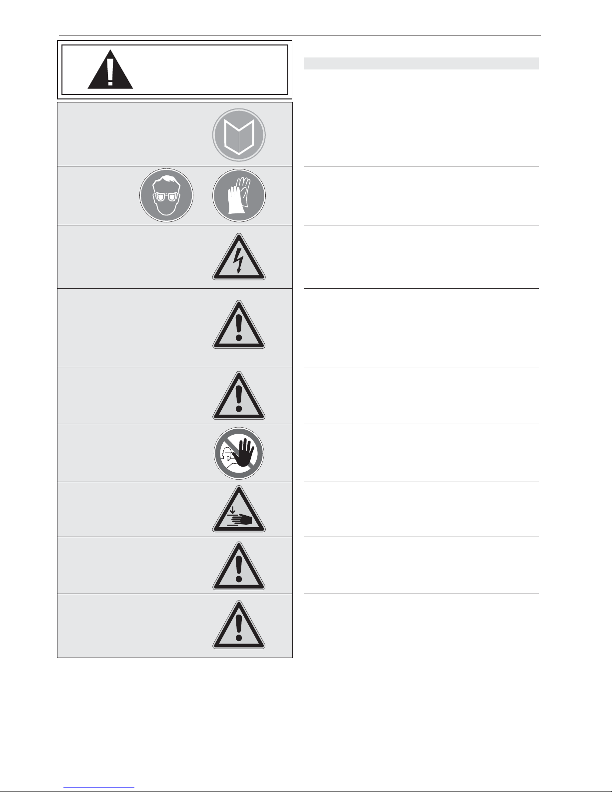
Inform yourself!
Read the operating instructions carefully.
Preventive and corrective maintenance on the tool may
only be carried out by trained personnel.
Protect yourself!
When operating the tool, wear eye, face and hand protection (cut-proof gloves).
Power source!
Before starting preventive or corrective maintenance, remove battery from the tool. Always inspect the electrical
plug and cable before use. If damaged, they must be
replaced by qualifi ed personnel.
Warning:
Strap will snap forward!
When cutting the strap, hold the upper portion and stand
safely away from the strap.
Caution:
The lower strap will snap forward.
Warning:
Strap could break!
Do not stand in line with the strap while it is tensioned.
The strap could break!
Caution:
Only strap packed goods!
Do not put hands or other parts of the body between the
strap and the package during the strapping process.
Caution:
Danger of crushing!
Do not put your fi ngers into the tension wheel area.
Do not use water!
Do not use water or steam to clean the tool.
Only original spare parts may be used!
Using non-original spare parts will void the warranty and
any liability.
Use for the intended purpose
This tool is designed for strapping packages, pallet loads
and the like.
The tool is designed for use with plastic straps (polypropylene and polyester).
Possible misuse
The use of steel straps is not possible.
WARNING
ATENCIÓN
Page 11

11
07.09
SIGNODE BXT2
3 SICHERHEITSVORSCHRIFTEN
Informieren Sie sich!
Vor dem Gebrauch des Gerätes die Betriebsanleitung
sorgfältig lesen.
Das Gerät darf nur von ausgebildetem Personal gewartet
und instandgesetzt werden.
Schützen Sie sich!
Beim Arbeiten Augen-, Gesichts- und Handschutz
(schnittfeste Handschuhe) tragen.
Energiequelle!
Vor Wartungs- und Instandsetzungsarbeiten: Akku aus
dem Gerät ziehen. Kontrollieren Sie vor jeder Benutzung
Stecker und Kabel und lassen Sie diese bei Beschädigung von einem Fachmann ersetzen.
Achtung:
Band springt auf!
Beim Durchschneiden des Bandes den oberen Teil
festhalten und abseits stehen.
Achtung:
Der untere Bandteil wird aufspringen.
Achtung:
Band kann reissen!
Beim Spannen kann das Band reissen! Nicht in der
Flucht des Bandes stehen.
Vorsicht:
Nur Packgut umreifen!
Während dem Umreifen dürfen sich keine Hände und andere Körperteile zwischen Band und Packgut befi nden.
Vorsicht: Quetschgefahr!
Mit den Fingern nicht in den Spannrad-Bereich greifen.
Kein Wasser verwenden!
Zum Reinigen des Gerätes dürfen weder Wasser noch
Wasserdampf verwendet werden.
Verwenden Sie nur Original-Ersatzteile!
Die Verwendung von anderen Ersatzteilen schliesst
Garantieleistungen und Haftpfl icht aus.
3 DISPOSICIONES DE SEGURIDAD
¡Infórmese!
Lea cuidadosamente este instructivo antes de utilizar el
aparato.
El aparato sólo deberá recibir mantenimiento y ser reparado por personal cualifi cado.
¡Protéjase!
Al trabajar use protecciones de seguridad ocular, facial y
manual (guantes irrompibles).
Fuente de energía!
Retire el acumulador del aparato antes de efectuar revisiones o reparaciones. Antes de utilizar el equipo revise
los cables y conexiones; en caso de daños deje que un
especialista los substituya.
Cuidado:
¡La cinta salta bruscamente!
Al cortar alguna cinta fl ejada, sostenga la parte superior
y hágase a un lado.
Atención:
La parte inferior del fl eje saltará bruscamente.
Cuidado:
¡La cinta pudiera romperse!
¡Durante el tensado del fl eje, éste puede romperse!,
colóquese fuera de su trayectoria.
Cuidado:
¡Sólo fl eje el embalaje!
Cuidese de no meter las manos ni otras partes corporales entre el fl eje y el embalaje.
Cuidado:
¡Peligro de machacamiento!
No introduzca sus dedos en el área de la rueda tensora.
¡No utilice agua!
Para la limpieza del aparato no deberá utilizarse agua
ni vapor.
¡Utilice solamente piezas de recambio originales!
La utilización de otras piezas de recambio no suministradas, anula los derechos de garantía y nuestra
responsabilidad civil.
Utilización conforme a las disposiciones
Este aparato está destinado para el fl ejado de paquetes,
para la paletización de cargas, etc.
El aparato está destinado para el empleo de cintas
plásticas de fl ejar en polipropileno y poliéster.
Posible uso impropio
El fl ejado con cintas de acero no es posible con ésta
fl ejadora.
Bestimmungsgemässe Verwendung
Dieses Gerät ist zum Umreifen von Paketen, Palettenladungen usw. bestimmt.
Das Gerät ist für das Umreifen mit Verpackungs-Kunststoffbändern (Polypropylen und Polyester) bestimmt.
Möglicher Missbrauch
Das Umreifen mit Stahlband ist mit diesem Gerät nicht
möglich.
Page 12
12
07.09
SIGNODE BXT2
AUTO
MAN.
SOFT
AUTO
MAN.
SOFT
+ / -
+ / -
AUTO
MAN.
SOFT
AUTO
MAN.
SOFT
+ / -
+ / -
4 DESCRIPTION
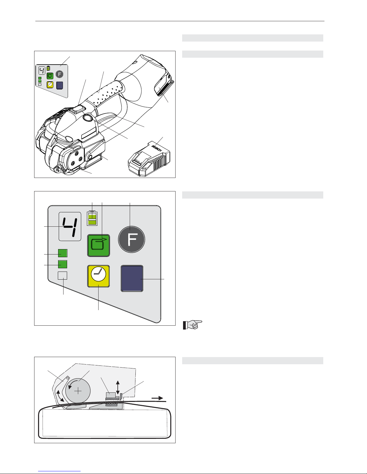
4.1 CONSTRUCTION
1 Operating panel
2 Tension button „Strap tensioning/welding“ (Fully-Auto)
3 Handle
4 Battery, 14.4 V
5 Rocker lever
6 Welding button „Welding/cutting“ (manual)
7 Welding/Cutting
8 Tensioning
9 Battery charger
For detailed information, refer to the operating instruc tions for the battery and battery charger.
4.2 OPERATING PANEL
1 LED indicator „Battery charge“
2 Push button „Strap tension“
3 Push button „Function“
4 Push button „Mode of operation“
5 Push button „Welding time“
6 LED indicator „Soft tension“
7 LED indicator „Manual strapping“ (continuous
green light)
8 LED indicator for:
– Semi-Automatic strapping (continuous green light)
– Full-Automatic strapping (fl ashing green light)
9 Digital display for:
– Strap tension (1–9)
– Welding time (1–7)
– Cooling time (count down 3,2,1)
– Fault indication
For detailed information/adjustments, refer to
chapter 5 and 6.
Fig. 1
12 3
4
5
6
7
8
9
Fig. 2
4.3 FUNCTION
– Clamping of the straps by tooth plate on rocker
(3/1).
– Tensioning by feed wheel (3/2) counter clockwise.
– Friction welding (3/3) of the straps.
– Upper strap is cut by knife (3/4).
Fig. 3
1
2
3
4
1
2
3
4
5
6
7
8
9
Page 13
13
07.09
SIGNODE BXT2
4 BESCHREIBUNG
4.1 AUFBAU
1 Bedienpanel
2 Spanntaste „Band Spannen/Schweissen“ (Vollautom.)
3 Traggriff
4 Akku, 14,4 V
5 Wippenhebel
6 Schweisstaste “Schweissen/Abschneiden“ (Manuell)
7 Schweissen/Abschneiden
8 Spannen
9 Akku Ladegerät
Für detaillierte Angaben, siehe separat beiliegende
Betriebsanleitung für den Akku und das Ladegerät.
4.2 BEDIENPANEL
1 LED-Anzeige „Akku-Ladezustand“
2 Drucktaste „Spannkraft“
3 Drucktaste „Funktion“
4 Drucktaste „Betriebsart“
5 Drucktaste „Schweisszeit“
6 LED-Anzeige „Softspannung“
7 LED-Anzeige „Manuelles Umreifen“ (grünes
Dauerlicht)
8 LED-Anzeige für:
– Halbautomatisches Umreifen (grünes Dauerlicht)
– Vollautomatisches Umreifen (grünes Blinklicht)
9 Segment-Anzeige für:
– Spannkraft (1–9)
– Schweisszeit (1–7)
– Abkühlzeit (count down 3,2,1)
– Fehleranzeige
Für die einzelnen Beschreibungen/Einstel lungen, siehe Kapitel 5 und 6.
4.3 FUNKTIONSPRINZIP
– Festklemmen der Bänder durch Zahnplatte in
Wippe (3/1).
– Spannen über Spannrad (3/2) im Gegenuhrzeiger sinn.
– Verschweissen der Bänder im Reibschweiss verfahren (3/3).
– Mit Abschneidmesser (3/4) oberes Band abschnei den.
4 DESCRIPCIÓN
4.1 CONSTRUCCIÓN
1 Panel de operación
2 Tecla de tensado “tensado de fl eje/soldadura“
(todo automatico)
3 Asa portadora
4 Acumulador, 14,4 V
5 Palanca basculante
6 Tecla de soldadura “soldar/cortar“ (manual)
7 Corte y soldadura
8 Tensora
9 Cargador del acumulador
Para informes detallados vea el manual de operación
adjunto para el acumulador y el cargador.
4.2 PANEL DE OPERACIÓN
1 Indicador LED “Carga de acumulador”
2 Tecla “Tensión”
3 Tecla “Función”
4 Tecla “Modo de operación”
5 Tecla “Tiempo de soldadura”
6 Indicador LED “Tensión baja”
7 Indicador LED “Flejado manual” (luz verde continua)
8 Indicador LED para:
– Flejado semiautomático (luz verde continua)
– Flejado completamente automático (luz verde inter mitente)
9 Indicador digital para:
– Tensión (1–9)
– Tiempo de soldadura (1–7)
– Lapso de enfriamiento (cuenta regresiva 3,2,1)
– Indicador de fallas
Para informes y ajustes detallados observe los
capítulos 5 y 6.
4.3 PRINCIPIO DE OPERACIÓN
– Sujeción de bandas mediante placa dentada en el
balancín (3/1).
– Tensado de la cinta con la rueda tensora (3/2) giran do contra el sentido del reloj.
– Soldadura de las cintas por el método de soldadura
por fricción (3/3).
– Corte de la cinta superior con la cuchilla de corte
(3/4).
Page 14
14
07.09
SIGNODE BXT2
5 ORERATING INSTRUCTIONS
1
2
34
Fig. 4
1
Fig. 5
5.1 CHARGING THE BATTERY
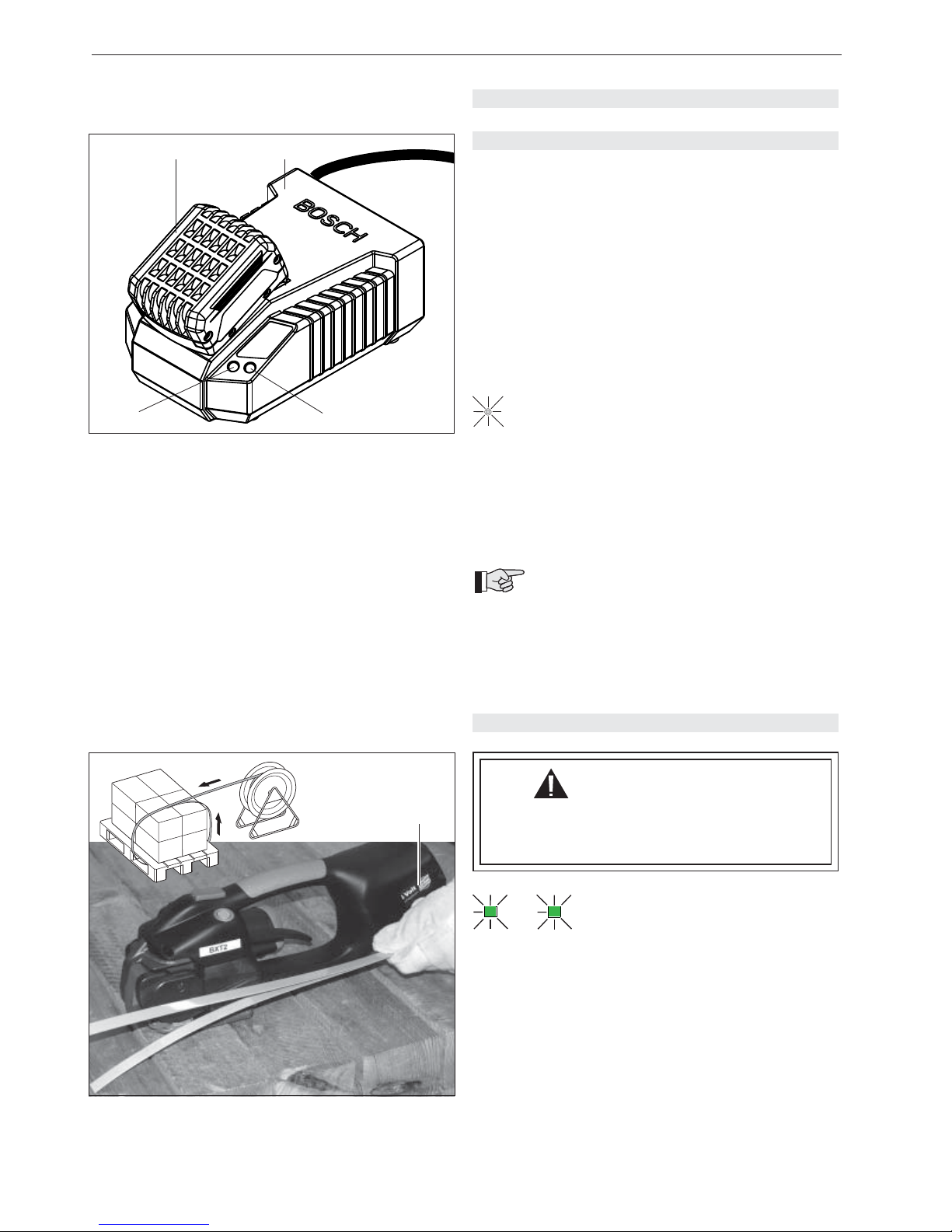
– Connect battery charger AL 1860 CV (4/2) to mains
supply.
– Insert battery 14.4 V (4/1) into battery charger slot.
The charging process and error functions are indicated
by a green (4/3) and a red light (4/4).
For detailed information, refer to the operating instruc tions for the battery and battery charger.
Charging times:
– First charging of a new battery, min. 5 hr.
– Recharging of empty battery:
approx. 20 to 45 minutes
Continuous lighting of the green LED (4/3)
indicates that the battery is fully charged.
The maximum charging current fl ows when the tempe-
rature of the battery is between 15–40°C (59–104°F).
Avoid charging the battery at temperatures below 0°C
(32°F) and above 40°C (104°F).
Battery can be charged at any time regardless of charging status!
If the battery is not to be used for a longer
period (several days), it should be removed from the tool and charged/stored in the battery
charger.
To remove battery from tool, depress button on battery
and at the same time pull out battery.
+
5.2 OPERATING THE TOOL
This description assumes that the
mode of operation is adjusted to
„Semi-Auto“ (refer to chapter 5.5).
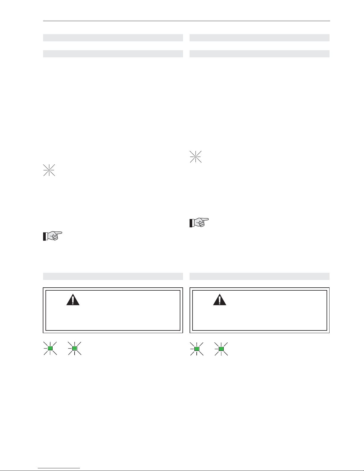
– Insert charged battery (5/1) into strapping tool.
– Place strap round goods to be packaged, so that the
straps lie one above the other on top of package. The
start of the strap is underneath. Hold the straps with
the left hand so that the strap start projects approxima tely 20 cm (8“) out of the hand.
AUT
O
MAN.
+
WARNING
Wear safety glasses. Stand to one side of the
strap when tensioning. Make sure all bystanders
are clear before proceeding.
Page 15
15
07.09
SIGNODE BXT2
5 BEDIENUNG
5.2 BEDIENUNG DES GERÄTES
Bei dieser Beschreibung wird davon
ausgegangen, dass die Betriebsart
„Halbautomatisch“ eingestellt ist
(siehe Kapitel 5.5).
– Geladener Akku (5/1) in Gerät einsetzen.
– Das Band um das Packgut legen, so dass die
Bänder auf der Oberseite übereinander liegen. Der
Bandanfang liegt unten. Bänder mit der linken Hand
so fassen, dass der Bandanfang ca. 20 cm von der
Hand entfernt ist.
5.1 AKKU AUFLADEN
– Ladegerät AL 1860 CV (4/2) an Netzspannung
anschliessen.
– Akku (14,4 V) (4/1) in den Ladeschacht einsetzen.
Ladevorgang und Fehlfunktionen werden durch eine
grüne (4/3) und eine rote Anzeige (4/4) signalisiert.
Für detaillierte Angaben, siehe separat beiliegende
Betriebsanleitung für den Akku und das Ladegerät.
Ladezeiten:
– Erstmaliges Laden eines neuen Akkus, min. 5 Std.
– Aufl aden eines entleerten Akkus:
ca. 20–45 Minuten
Das Dauerlicht der günen LED-Anzeige (4/3)
signalisiert, dass der Akku vollständig geladen ist.
Der maximale Ladestrom fl iesst, wenn die Temperatur
des Akkus zwischen 15–40°C liegt. Akku-Temperaturen
unter 0°C und über + 40°C beim Ladevorgang vermeiden.
Akku kann jederzeit unabhängig vom Ladezustand
geladen werden!
Wenn der Akku für längere Zeit (Tage) nicht
gebraucht wird, soll der Akku aus dem Gerät
entfernt und im Ladegerät aufgeladen/aufbewahrt
werden.
Um den Akku aus dem Gerät zu entfernen, Taste am
Akku drücken und gleichzeitig Akku herausziehen.
+
AUT
O
MAN.
+
5 OPERACIÓN
5.2 OPERACIÓN DEL APARATO
En esta descripción se asume que el
modo de operación se encuentra
ajustado en “semi-automático”
(vea Cap. 5.5).
– Introduzca el acumulador cargado y sujételo con el
muelle de soporte (5/1).
–
Coloque la cinta alrededor del embalaje de manera
que queden sobrepuestas en su parte superior. El
cabo de la cinta deberá estar abajo. Tome las
cintas con la mano izquierda de forma que el cabo
quede a unos 20 cm adelante.
5.1 CARGADO DEL ACUMULADOR
– Conectar el cargador AL 1860 CV (4/2) a la red
eléctrica.
– Colocar acumulador (14,4 V) (4/1) en el enchufe de
carga. El proceso de cargado y las anomalías se se-
ñalan mediante un indicador verde (4/3) y uno rojo
(4/4).
Para mayores detalles vea el manual de operación
adjunto para el acumulador y el cargador.
Tiempos de cargado:
– La primera vez para un acumulador nuevo, mínimo 5
horas.
– Recargado de acumulador vacío:
aprox 20 a 45 min.
El encendido continuo del LED verde (4/3) señala
que el acumulador esta completamente cargado.
La corriente máxima fl uye cuando el nivel de tempe-
ratura del acumulador se encuentra entre 15 y 40°C.
Evite cargar el acumulador a temperaturas inferiores a
los 0°C.
El acumulador puede ser cargado siempre, independientemente de su estado de carga (!)
Si se contempla no utilizar el acumulador
por periodos prolongados (días), extráigalo
del aparato y cárguelo en el cargador.
Para extraer el acumulador del aparato, oprima la tecla
junto a éste y remuévalo simultáneamente.
+
AUT
O
MAN.
+
ATENCIÓN
Use lentes de seguridad. Al tensar el fl eje coló-
quese a un lado. Cerciórese de que no se
encuentre nadie en las inmediaciones.
ACHTUNG
Schutzbrille tragen. Beim Spannen des Bandes
auf die Seite stehen. Stellen Sie sicher, dass sich
keine Zuschauer im Gefahrenbereich aufhalten.
Page 16
16
07.09
SIGNODE BXT2
Fig. 6
1
AUTO
MAN.
SOFT
AUTO
MAN.
SOFT
+ / -
+ / -
1
Fig. 8
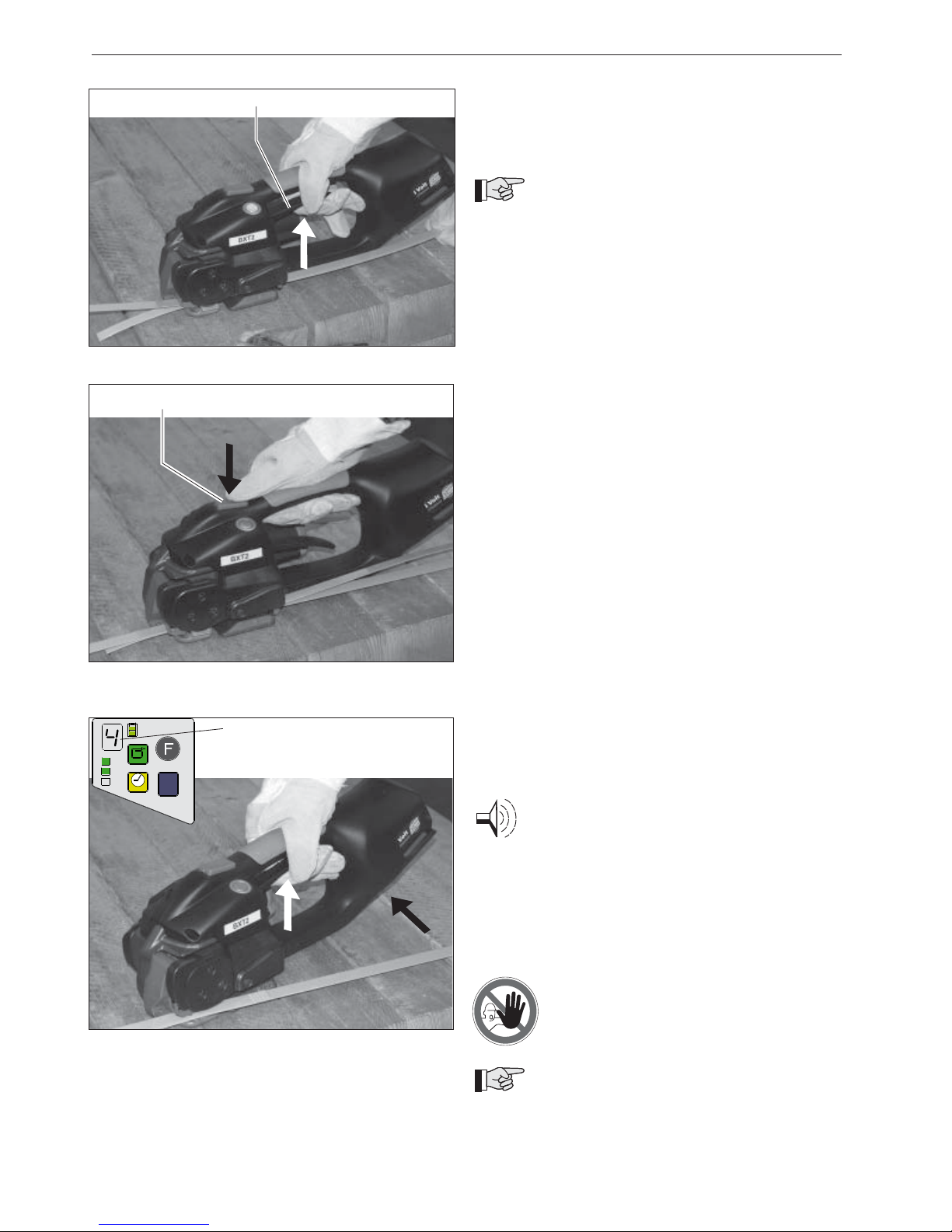
– Take the tool in the right hand and lift the rocker lever
(6/1) towards the handle.
– Slide the straps, one on top of the other, into the tool
up to the stop.
The strap lead is now approximately 5 cm (2“)
beyond the tool.
– Release the rocker lever.
– Press the tension button (7/1) until the preselected
strap tension is reached. The tool switches over
automatically as soon as the strap tension has
been reached. The straps are welded and the
upper strap cut off.
– The tensioning process can be stopped at any time
and continued again. In order to release the strap
tension after the tensioning process, lift the rocker
lever (6/1) towards the handle.
– The strap tension can be adjusted on the operating
panel (see Chapter 5.6).
Tensioning – welding:
To perform welding before the strap has been tensioned,
fi rst switch to operating mode „Manual“. However, the
tensioning button must be pressed once before welding.
– The digital display (8/1) indicates the cooling time of
the sealing. After fi nishing the friction welding, the
digital display counts backwards (3,2,1). Do not
remove the tool during this time!
Audible signal sounds once:
The sealing cycle is fi nished.
– After the audible signal sounds, raise the rocker lever
up to the handle.
– Swing the tool away from the strapping backwards and
to the right. If the tool is removed too early, the
audible signal will sound several times.
– Check the seal (refer to chapter 5.3).
Never transport or move packaged goods
with incorrectly welded seals.
If the tool is used in a dirty environment, it is
recommended that it should be cleaned daily.
In particular the tension wheel and the tooth plate should
be checked for damage and kept clean. This is best performed by blasting with compressed air (wear goggles).
Fig. 7
1
Page 17
17
07.09
SIGNODE BXT2
– Gerät mit der rechten Hand fassen und Wippenhebel
(6/1) gegen den Traggriff ziehen.
– Die übereinanderliegenden Bänder bis zum Anschlag
in das Gerät einlegen.
Der Bandanfang ragt ca. 5 cm über das Gerät
hinaus.
– Wippenhebel loslassen.
– Spanntaste (7/1) betätigen bis, die vorgewählte Band spannung erreicht ist. Sobald die Bandspannung
erreicht ist, schaltet das Gerät automatisch um.
Die Bänder werden verschweisst und das obere
Band abgeschnitten.
– Der Spannprozess kann jederzeit angehalten und
wieder fortgesetzt werden. Die Bandspannung kann
durch Betätigung des Wippenhebels (6/1) wieder
gelöst werden.
– Die Bandspannung kann über das Bedienpanel ein gestellt werden (siehe Kapitel 5.6).
Spannen – Verschweissen:
Soll eine Verschweissung ausgelöst werden, ohne dass
eine Bandspannung anliegt, muss zuerst auf Betriebsart
„Manuell“ umgeschaltet werden. Vor dem Schweissen
einmal die Spanntaste betätigen.
– Die Segment-Anzeige (8/1) zeigt die Abkühlzeit des
Verschlusses an. Nach einem ausgeführten Reib schweissverschluss zählt die Segment-Anzeige zurück
(3,2,1). Während dieser Zeit darf das Gerät noch nicht
entnommen werden!
Akustisches Signal ertönt einmal:
Der Schweissvorgang ist beendet.
– Nachdem das akustische Signal ertönt, Wippenhebel
gegen den Traggriff ziehen.
– Das Gerät nach hinten rechts von der Umreifung weg schwenken. Wird das Gerät zu früh entfernt, ertönt
das akustische Signal mehrmals.
– Verschlusskontrolle durchführen (siehe Kapitel 5.3).
Transportieren oder bewegen Sie niemals
ein Packgut mit nicht korrekt ausgführtem
Reibschweissverschluss.
Bei starkem Schmutzanfall empfi ehlt es sich,
das Gerät regelmässig (täglich) zu reinigen.
Besonders sollten das Spannrad und die Zahnplatte auf
Beschädigung kontrolliert und sauber gehalten werden.
Dies geschieht am einfachsten durch Ausblasen mit
Druckluft (Schutzbrille tragen).
– Tome el aparato con la mano derecha y tire la pa-
lanca basculante (6/1) contra el asa portadora.
– Las cintas sobrepuestas deberán ser insertadas
hasta el tope en el aparato.
El inicio de la cinta deberá sobresalir unos
5 cm por delante del aparato.
– Suelte la palanca basculante.
– Oprima la tecla de tensado (7/1) hasta alcanzar la
tensión preseleccionada. El equipo automáticamente
conmutará al paso siguiente al llegar a este punto.
Los fl ejes se sueldan y el fl eje superior será
cortado.
– El proceso de tensado puede ser interrumpido en
cualquier momento y reiniciado después. La tensión
del fl eje puede ser liberada levantando la palanca
basculante (6/1) hacia el asa.
– La tensión de la cinta puede ser preajustada mediante
el panel de operación (ver cap. 5.6).
Tensado – Soldadura:
Para efectuar una soldadura sin presencia de tensión en
el fl eje, habrá que conmutar antes al modo de operación
“Manual”. Sin embargo para ello deberá oprimirse la
tecla de tensado.
– El indicador digital (8/1) muestra el lapso de enfria miento de la soldadura. Luego de fi nalizar la soldadura
por fricción, aparecerá una cuenta regresiva (3,2,1).
¡No extraiga el aparato durante este lapso!
Señal audible suena una vez:
El ciclo de soldado ha terminado.
– Luego de escuchar la señal audible levante la palanca
basculante hacia el asa.
– Después deslice el aparato hacia atrás y a la derecha
para extraerlo del fl eje. Si el aparato es retirado antes
de tiempo sonará la señal acústica varias veces.
– Realice una inspección de la soldadura (capítulo 5.3).
Nunca transporte ni mueva embalajes
cuya soldadura por fricción no haya
sido correctamente realizada.
Se recomienda limpiar el aparato regular-
mente (a diario), o cada vez que se ensucie.
En especial deberán revisarse posibles daños en la rueda
tensora y la placa dentada y mantenerlas limpias. La
forma más simple es utilizando un soplete de aire comprimido (¡protéjase con lentes de seguridad!).
Page 18
18
07.09
SIGNODE BXT2
1
2
3
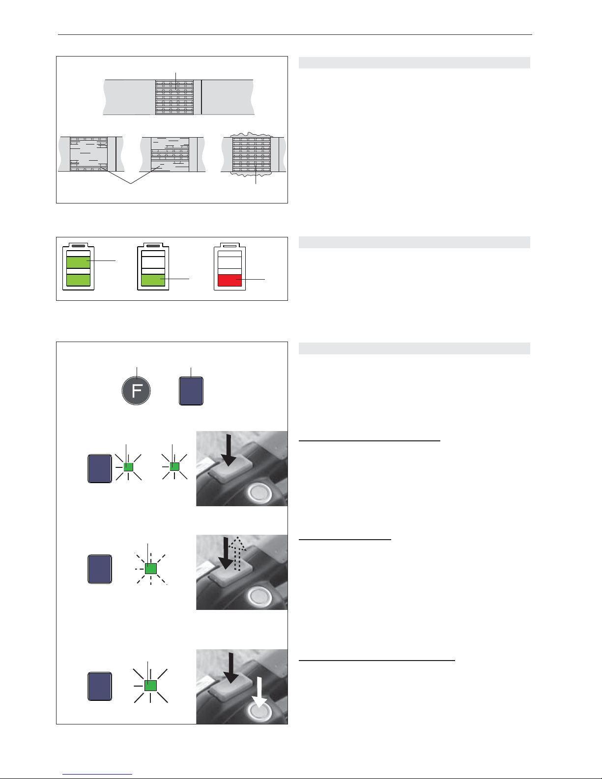
5.3 CHECKING THE SEAL
– Check appearance of seal (see fi g. 9) regularly. If the
straps are poorly welded, check the welding time
setting (refer to chapter 5.8).
1 Good seal (the complete surface is cleanly welded
without excess material being forced out sideways).
2 Poorly welded seal (not welded over the complete
surface), welding time too short.
3 Poorly welded seal (excess material is forced out
sideways), welding time too long.
5.4 CHECKING BATTERY CHARGE
– Read off battery charge on LED indicator (Fig. 10):
1 = Green indicator: maximum battery charge
2 = Green indicator: good battery charge
3 = Red indicator: empty battery
(Battery must be charged soon)
Fig. 9
Fig. 10
1
3
2
➟
1
2
Fig. 11
MAN.
AUTO
MAN.
SOFT
➟
fl ashing / intermitente /
blinkend
AUTO
MAN.
SOFT
➟
AUTO
MAN.
SOFT
➟
AUTO
MAN.
SOFT
5.5 SETTING MODE OF OPERATION
– Press „Function“ button (11/1) briefl y. The digital
display will show „F“ (Function). The present mode of
operation is shown.
– Then press the „Mode of operation“ button (11/2)
briefl y until the desired mode of operation is shown.
Semi-Auto strapping (Standard):
Strapping is performed by pressing the tensioning button.
When the strap tension is reached, welding and cutting is
performed automatically.
– Press the „Mode of operation“ button (11/2). When the
„AUTO“ (11/3) and „MAN“ (11/4) LED indicators light
continuous green „Semi-Auto“ mode of operation is
selected.
Fully-Auto strapping:
Strapping is performed by tapping tensioning button.
Tensioning, welding and cutting are performed fullyautomatically.
– Press the „Mode of operation“ button (11/2). When the
„AUTO“ LED indicator (11/5) fl ashes green „Fully-
Auto“ mode of operation is selected.
Stop of Fully-Auto sequence:
By pressing tension- /welding button or raising rocker
lever.
Manual strapping (manual welding):
Strapping is performed by fi rst pressing the tensioning
button (1.). When the tension is reached, press the
welding button (2.).
– Press the „Mode of operation“ button (11/2). When the
„MAN“ LED indicator (11/6) lights continous green
„Manual“ mode of operation is selected.
1.
2.
AUT
O
MAN.
+
AUT
O
34
5
6
Page 19

19
07.09
SIGNODE BXT2
5.3 VERSCHLUSSKONTROLLE
– Verschluss regelmässig auf sein Aussehen überprüfen
(siehe Fig. 9). Bei schlecht geschweissten Bändern:
Einstellung der Schweisszeit überprüfen (siehe
Kapitel 5.8).
1 Gute Schweissung (die ganze Verschlussfl äche ist
sauber verschweisst, ohne dass überschüssiges
Material seitlich herausgedrückt wird).
2 Schlechte Schweissung (Schweissung nicht auf
ganzer Verschlussfl äche), Schweisszeit ist zu kurz
eingestellt.
3 Schlechte Schweissung (überschüssiges Material wird
seitlich herausgepresst), Schweisszeit ist zu lang ein gestellt.
5.4 AKKU-LADEZUSTAND PRÜFEN
– Ladezustand des Akkus an der LED-Anzeige (Fig. 10)
überprüfen:
1 = Grüne Anzeige: Maximale Ladung
2 = Grüne Anzeige: Gute Ladung
3 = Rote Anzeige: Minimale Ladung
(Akku muss bald geladen werden)
5.5 BETRIEBSARTEN EINSTELLEN
– Drucktaste „Funktion“ (11/1) kurz betätigen. Segment Anzeige „F“ (Funktion) erscheint. Die aktuell einge stellte Betriebsart wird angezeigt.
– Danach Drucktaste „Betriebsart“ (11/2) kurz betätigen
bis die gewünschte Betriebsart angezeigt wird.
Halbautomatisches Umreifen (Standard):
Das Umreifen erfolgt auf Tastendruck. Bei Erreichen der
Bandspannung wird automatisch verschweisst und abgeschnitten.
– Drucktaste „Betriebsart“ (11/2) betätigen. Leuchten die
LED-Anzeigen „AUTO“ (11/3) und „MAN (11/4) grün im
Dauerlicht ist die Betriebsart „Halbautomatisch“ ein gestellt.
Vollautomatisches Umreifen:
Das Umreifen erfolgt nach Antippen der Spanntaste.
Spannen, Verschweissen und Abschneiden erfolgt vollautomatisch.
– Drucktaste „Betriebsart“ (11/2) betätigen. Blinkt die
LED-Anzeige „AUTO“ (11/5) grün, ist die Betriebsart
„Vollautomatisch“ eingestellt.
V ollautomatischen Ablauf stoppen:
Durch Betätigung der Spann- /Schweisstaste oder
ziehen des Wippenhebels.
Manuelles Umreifen (manuelles Verschweissen):
Das Spannen erfolgt auf Tastendruck (1.) nach Erreichen
der Bandspannung, Drucktaste (2.) „Schweissen“
betätigen.
– Drucktaste „Betriebsart“ (11/2) betätigen. Leuchtet die
LED-Anzeige „MAN“ (11/6) grün im Dauerlicht, ist die
Betriebsart „Manuell“ eingestellt.
5.3 INSPECCIÓN DE SOLDADURA
– Revise siempre el aspecto de la soldadura (ver fi g.
9). Si la calidad del soldado no es satisfacto-
ria: Revise el tiempo de soldadura (ver capítulo
5.8).
1 Buena soldadura (El área de la unión se encuent-
ra perfectamente soldada, y sin material fundido exce dente saliendo a los lados).
2 Soldadura defectuosa (soldadura no cubre toda la
superfi cie de la unión), el tiempo de soldadura está
ajustado insufi cientemente.
3 Soldadura defectuosa, (material excedente salien do a los lados), el tiempo de soldadura está sobre pasado.
5.4 COMPROBAR CARGA DEL ACUMULADOR
– Estado de carga del acumulador en el indicador LED
(Fig. 10):
1 = Indicación verde: Carga máxima
2 = Indicación verde: Carga sufi ciente
3 = Indicación roja: Carga mínima
(El acumulador deberá ser recargado a corto
plazo).
5.5 AJUSTAR MODOS DE OPERACIÓN
– Oprima brevemente la tecla de “Función” (11/1). El
indicador digital mostrará “F” (Función). Se mostrará la
función actual activa.
– Luego oprima brevemente la tecla “Modo de operaci ón” (11/2) hasta que se muestre el modo de operación
deseado.
Flejado semi-automático (estándar):
El fl ejado se realiza oprimiendo la tecla de tensado. Al
alcanzar la tensión de fl eje, éste es soldado y cortado
automáticamente.
– Oprima la tecla “Modo de operación” (11/2); si los in dicadores LED “AUTO” (11/3) y “MAN” (11/4) enci enden en verde continuamente, está seleccionado el
modo de operación “Semi-automático”
Flejado completamente automático:
El fl ejado se realiza tocando apenas la tecla de tensado.
El tensado, soldadura y corte se realizan todos automáticamente.
– Oprima la tecla “Modo de operación” (11/2); si el
indicador LED “AUTO” (11/5) parpadea en verde, está
seleccionado el modo de operación “Todo automático”.
Detención de la secuencia “Todo automático”:
Oprimiendo la tecla de tensado/soldadura o levantado la
palanca basculante.
Flejado manual (soldadura manual):
El tensado se actúa oprimiendo la tecla (1). Al alcanzar
la tensión del fl eje oprima la tecla de “Soldadura” (2).
– Oprima lateral “Modo de operación” (11/2); si el indica dor LED “MAN” (11/6) enciende en verde conti nuamente, está seleccionado el modo de operación
“Manual”.
Page 20
20
07.09
SIGNODE BXT2
AUTO
MAN.
SOFT
+ / -
+ / -
➟
Fig. 12
1
2
3
=
➟
Fig. 14
1
2
3
=
➟
Fig. 13
1
2
3
=
AUTO
MAN.
SOFT
AUTO
MAN.
SOFT
AUTO
MAN.
SOFT
A)
1 2 3 4 5 6 7 8 9
900 1100 1300 1500 1700 1900 2100 2300 2500 N
200 247 292 337 382 427 472 517 560 lbs.
B)
1 2 3 4 5 6 7 8 9
400 520 640 760 880 1000 1120 1240 1500 N
88 116 143 170 197 224 252 279 335 lbs.
Fig. 15
1
2 3 4
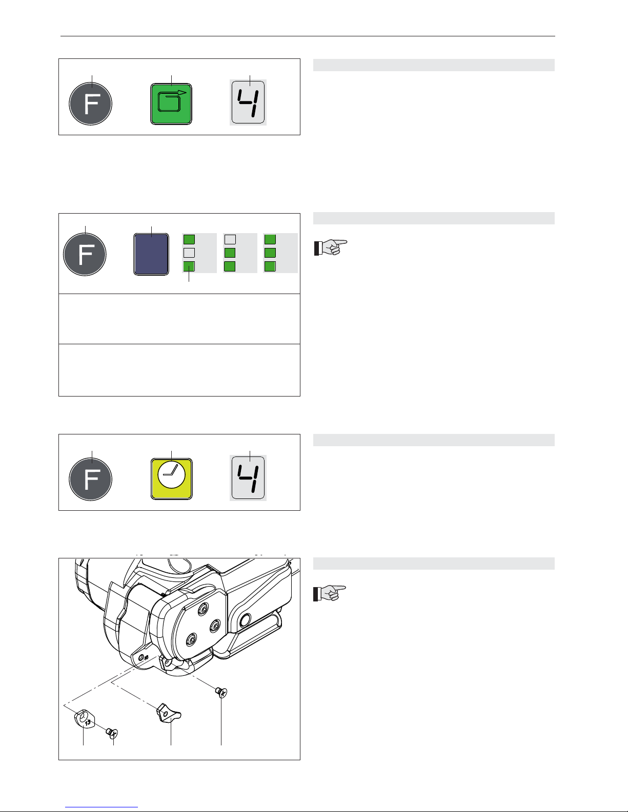
5.6 SETTING STRAP TENSION
– Press the „Function“ button (12/1) briefl y.
– Press the „Strap tension“ button (12/2) until the
fl ashing digital display (12/3) shows the required strap
tension. Wait two seconds until the new setting is
saved.
1 = min. strap tension approx. 400/900 N*
(88/200 lbs.) (PP)
9 = max. strap tension approx. 1500/2500 N*
(335/560 lbs) (PET)
* refer to Chapter 5.7
5.8 SETTING WELDING TIME
– Press the „Function“ button (14/1) briefl y.
– Press the „Welding time“ button (14/2) until the
fl ashing digital display (14/3) shows the required
welding time. Wait two seconds until the new setting is
saved.
1 = minimum welding time
7 = maximum welding time
5.7 SETTING SOFT TENSION
The following two strap tension ranges can
be set on the tool:
A = 900–2500 N (200–560 lbs.)
standard, PET straps
B = 400–1500 N (88–335 lbs.)
Soft tension*, PP straps
* Soft tension: tension wheel starts slowly. Prevents
excessive dirt on PP straps.
Setting soft tension:
– Press the „Function“ button (13/1) briefl y.
– Press the „Mode of operation“ button (13/2) several
times until the green „SOFT“ LED indicator (13/3)
lights up together with the desired mode of operation
(refer to chapter 5.5).
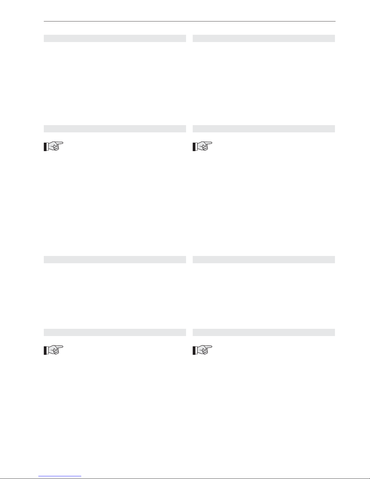
5.9 SETTING STRAP WIDTH
The tool can be used with three different strap
widths:
– 12–13 mm (1/2“)
– 15–16 mm (5/8“)
– 9–11 mm (option)
a) Change strap width from 12–13 mm to 15–16 mm
– Remove battery from tool.
– Release sunk screw (15/2) and remove strap stop
13 mm (15/1).
– Lift the rocker lever towards the handle, release
sunk screw (15/4) and remove strap guide 13 mm
(15/3).
Continuation page 22
Page 21
21
07.09
SIGNODE BXT2
5.6 SPANNKRAFT EINSTELLEN
– Drucktaste „Funktion“ (12/1) einmal kurz betätigen.
– Drucktaste „Spannkraft“ (12/2) mehrmals betätigen,
bis die blinkende Segment-Anzeige (12/3) die ge wünschte Spannkraft anzeigt (2 sec. warten bis Wert
gespeichert).
1 = minimale Spannkraft ca. 400/900 N* (PP)
9 = maximale Spannkraft ca. 1500/2500 N* (PET)
* siehe Kapitel 5.7
5.8 SCHWEISSZEIT EINSTELLEN
– Drucktaste „Funktion“ (14/1) einmal kurz betätigen.
– Drucktaste „Schweisszeit“ (14/2) mehrmals betätigen,
bis die blinkende Segment-Anzeige (14/3) die ge wünschte Schweisszeit anzeigt (2 sec. warten bis Wert
gespeichert).
1 = minimale Schweisszeit
7 = maximale Schweisszeit
5.7 SOFTSPANNUNG EINSTELLEN
Am Gerät können folgende zwei Bandspan nungsbereiche eingestellt werden:
A = 900–2500 N, Standard, PET Bänder
B = 400–1500 N, Softspannung*, PP Bänder
* Softspannung: langsames Anlaufen des Spann rades. Verhindert übermässiges Verschmutzen bei
PP-Band.
Softspannung einstellen:
– Drucktaste „Funktion“ (13/1) einmal kurz betätigen.
– Drucktaste „Betriebsart“ (13/2) mehrmals betätigen,
bis die grüne LED-Anzeige „SOFT“ (13/3) zusammen
mit der gewünschten Betriebsart aufl euchtet (siehe
Kapitel 5.5).
5.9 BANDBREITE EINSTELLEN
Das Gerät kann mit drei verschiedenen Band breiten betrieben werden:
– 12–13 mm
– 15–16 mm
– 9–11 mm (Optional)
a) Umbau von 12–13 mm auf 15–16 mm
– Akku aus Gerät ziehen.
– Senkschraube (15/2) lösen und Bandanschlag vorne
13 mm (15/1) entfernen.
– Wippenhebel gegen den Traggriff ziehen, Senk schraube (15/4) lösen und Bandführung 13 mm
(15/3) entfernen.
Fortsetzung Seite 23
5.6 AJUSTE DE GRADO DE TENSADO
– Oprima brevemente la tecla “Función” (12/1).
– Oprima la tecla “Tensión de fl eje” (12/2) hasta que el
indicador digital parpadeante (12/3) muestre la tensión
requerida. (espere unos dos segundos para que este
valor quede almacenado).
1 = Tensión mínima aprox. 400/900 N* (PP)
9 = Tensión máxima aprox. 1500/2500 N* (PET)
* ver capitulo 5.7
5.8 AJUSTE DEL TIEMPO DE SOLDADURA
– Oprima brevemente la tecla “Función” (14/1).
– Oprima la tecla “Tiempo de soldadura” (14/2) hasta
que el indicador digital parpadeante (14/3) muestre
el tiempo de soldadura requerido (espere unos dos
segundos para que este valor quede almacenado).
1 = Tiempo de soldado mínimo
7 = Tiempo de soldado máximo
5.7 AJUSTAR TENSIÓN SUAVE
En el aparato pueden seleccionarse dos rangos
de tensado de cinta:
A = 900–2500 N, estándar, cintas PET
B = 400–1500 N, Tensión suave*, cintas PP
* Tensión suave: Lentamente pone en funcionamiento
la rueda tensora, inhibe un ensuciamiento excesivo
con cintas PP.
Ajustar tensión suave:
– Oprima brevemente la tecla “Función” (13/1).
– Oprima el botón “Tiempo de soldadura” (13/2) varias
veces hasta que el LED verde “SOFT” (13/3) se
encienda junto con el modo de operación deseado
(ver capítulo 5.5).
5.9 AJUSTE DEL ANCHO DE LA CINTA
El aparato puede ser operado con tres dife-
rentes tipos de cinta:
– 12–13 mm
– 15–16 mm
– 9–11 mm (opcional)
a) Modifi cación de 12-13 mm a 15-16 mm
– Extraiga el acumulador del aparato.
– Afl oje el tornillo de cabeza perdida (15/2) y extraiga
el tope de cinta de 13 mm (15/1).
– Oprima la palanca basculante contra el asa de
sujeción, afl oje el tornillo de cabeza perdida (15/4) y
extraiga la guía de cinta de 13 mm (15/3).
Continúa en página 23
Page 22
22
07.09
SIGNODE BXT2
Fig. 16
1
2
3
4
5
7
6
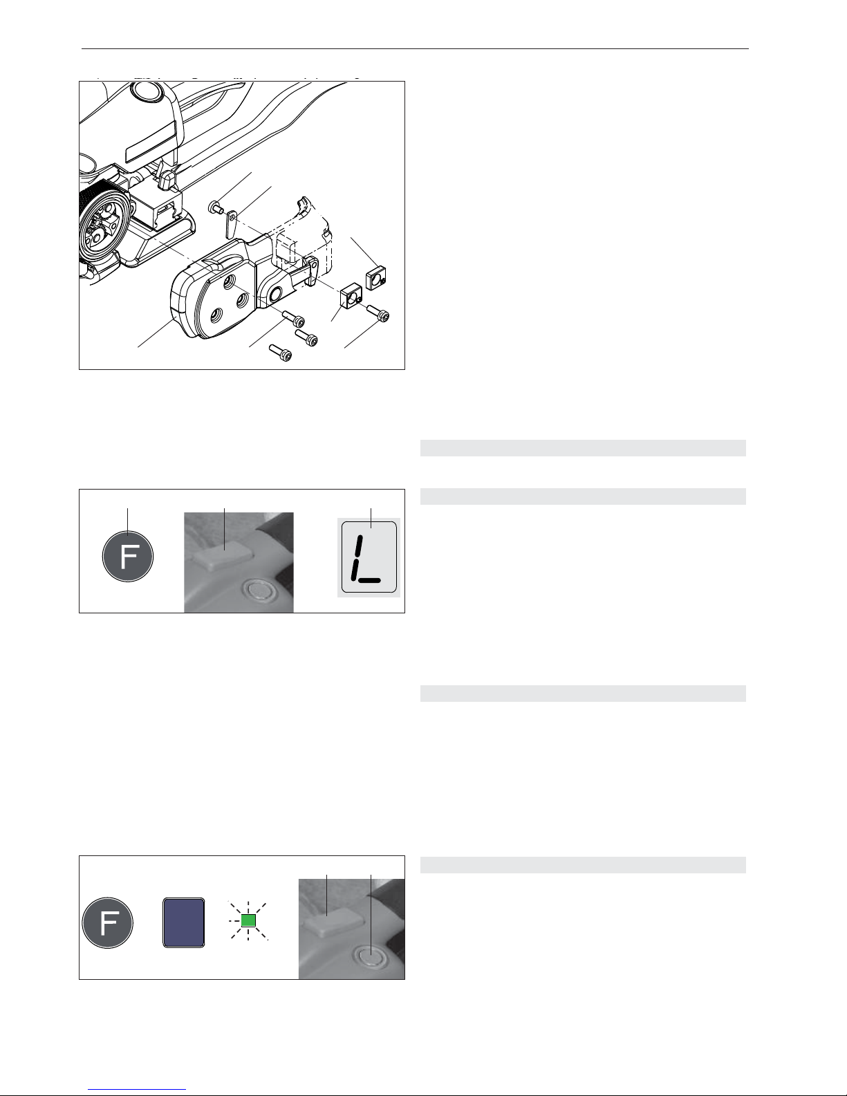
6.1 SWITCH TOUCH-PAD LOCK ON AND OFF
The touch-pad lock can be activated to prevent accidental changes to the settings.
– Press and hold the “Function“ button (17/1) and press
the tension button (17/2) at the same time. The audible
signal sounds and the keypad is blocked. If any key is
pressed, the digital display will show „L“ (Lock) (17/3).
– The keypad block is released in the same way as it is
activated.
6.2 SLEEP MODE
In order to avoid unnecessary battery consumption, the
tool changes after approx. 5 min. to sleep mode, if no
key is pressed.
– The „MAN“ LED indicator lights green.
– The digital display is switched off.
Sleep mode is switched off by touching any operating
panel element.
– Remove three cylinder screws (16/2).
– Lift the rocker lever towards the handle, remove cylin der screw (16/4) together with the strap stop rear
13 mm (16/3).
– Remove cover (16/1).
– Remove oval head screw (16/7) and remove strap
guide rear 13 mm (16/6) from lever.
– Install cover (16/1).
– Mount strap stop rear 16 mm (16/5).
b) Change strap width from 15–16 mm to 12–13 mm
– Mount 13 mm strap stop (15/1) and secure sunk
screw (15/2) with Loctite 222.
– Mount 13 mm strap guide (15/3) and secure sunk
screw (15/4) with Loctite 222.
– Remove strap stop rear 16 mm (16/5).
– Remove three cylinder screws (16/2) and remove
cover (16/1).
– Mount strap guide rear 13 mm (16/6).
– Install cover (16/1).
– Mount strap stop rear 13 mm (16/3).
6 SPECIAL FUNCTIONS
6.3 TOOL RESET
The tool reset may be used only if the rocker lever is
blocked:
– Change to mode of operation „Fully-Auto strapping“
(refer to Chapter 5.5).
– Press and hold welding button (18/1) and press
tension button (18/2). Tool reset starts (approx.
0.5 sec. welding).
If the tool reset could not successfully carried out,
please contact the Service Centre!
AUTO
MAN.
SOFT
➟
2
=
Fig. 18
1
AUT
O
Fig. 17
1
+=
2 3
fl ashing / intermitente /
blinkend
Page 23

23
07.09
SIGNODE BXT2
6.1 TASTENSPERRE EIN- UND AUSSCHALTEN
Die Tastensperre kann eingeschaltet werden, um unerwünschtes Verstellen der Einstellungen zu verhindern.
– Drucktaste „Funktion“ (17/1) betätigen und halten,
zusätzlich Spanntaste (17/2) betätigen. Akustisches
Signal ertönt–Tastatur ist gesperrt. Bei Betätigung
einer Drucktaste wird an der Segment-Anzeige „L“
(Lock) (17/3) angezeigt.
– Das Ausschalten der Tastensperre erfolgt gleich wie
das Einschalten.
6.2 SCHLAFMODUS
Um unnötigen Akku-Verbrauch zu vermeiden, wechselt
das Gerät nach ca. 5 min. ohne Geräte-Betätigung in
den Schlafmodus.
– LED „MAN“ leuchtet grün.
– Die Segment-Anzeige ist ausgeschaltet.
Durch Betätigen eines Bedienelementes wird der Schlafmodus wieder ausgeschaltet.
– Drei Zylinderschrauben (16/2) lösen.
– Wippenhebel gegen den Traggriff ziehen, Zylinder schraube (16/4) lösen und Anschlag hinten 13 mm
(16/3) entfernen.
– Abdeckung (16/1) entfernen.
– Linsenschraube (16/7) lösen und Bandführung hinten
13 mm (16/6) vom Hebel entfernen.
– Abdeckung (16/1) wieder montieren.
– Anschlag hinten 16 mm (16/5) montieren.
b) Umbau von 15–16 mm auf 12–13 mm
– Bandanschlag 13 mm (15/1) montieren (Senk schraube (15/2) mit Loctite 222 sichern).
– Bandführung 13 mm (15/3) montieren (Senk schraube (15/4) mit Loctite 222 sichern).
– Anschlag hinten 16 mm (16/5) entfernen.
– Drei Zylinderschrauben (16/2) lösen und Abdeckung
(16/1) entfernen.
– Bandführung hinten 13 mm (16/6) montieren.
– Abdeckung (16/1) wieder montieren.
– Anschlag hinten 13 mm (16/3) montieren.
6 SONDERFUNKTIONEN
6.3 GERÄTE-RESET
Der Geräte-Reset darf nur bei einer Blockade des Wippenhebels durchgeführt werden:
– In Betriebsart „Vollautomatisches Umreifen“ wechseln
(siehe Kapitel 5.5).
– Schweisstaste (18/1) betätigen und halten, danach
Spanntaste (18/2) betätigen. Geräte-Reset startet
(für ca. 0,5 sec. wird geschweisst).
Konnte der Geräte-Reset nicht erfolgreich durchgeführt
werden, bitte Servicestelle kontaktieren!
6.1 BLOQUEO Y DESBLOQUEO DEL TECLADO
El bloqueo del teclado puede activarse para prevenir
cambios indeseados a los ajustes preestablecidos.
– Oprima la tecla “Función” (17/1) y manténgala oprimi da simultáneamente con la tecla de tensión (17/2).
Una señal acústica avisará que el teclado ha sido
bloqueado. Al apretar cualquier tecla el indicador
digital (17/3) mostrará una “L” (Lock) (bloqueado).
– El desbloqueo se realiza en la misma forma que su
activación.
6.2 MODO EN GUARDIA DURMIENTE
Para ahorrar energía de la batería, el equipo se conmuta
a este modo luego de 5 minutos de no ser operado.
– El indicador de LED “MAN” se enciende en verde.
– El indicador digital se apaga completamente.
El modo de guardia durmiente se desactiva al tocar
cualquier elemento del panel de control.
– Afl oje los tres tornillos cilíndricos (16/2).
– Lleve la palanca basculante hacia el asa, extraiga el
tornillo cilíndrico (16/4) junto con el tope de cinta
trasero de 13 mm (16/3).
– Extraiga la cubierta (16/1).
– Extraiga el tornillo lenticular (16/7) y quite la guía de
fl eje posterior de 13 mm (16/6) de la palanca.
– Reinstale la cubierta (16/1).
– Coloque el tope de cinta trasero de 16 mm (16/5).
b) Modifi cación de 15-16 mm a 12-13 mm
– Coloque el tope de cinta de 13 mm (15/1). Asegure el
tornillo de cabeza perdida (15/2) con Loctite 222.
– Coloque la guía de cinta de 13 mm (15/3). Asegure el
tornillo de cabeza perdida (15/4) con Loctite 222.
– Extraiga el tope de cinta posterior de 16 mm (16/5).
– Extraiga los tres tornillos cilíndricos (16/2) y la cubierta
(16/1).
– Coloque la guía de cinta de 13 mm (16/6).
– Reinstale la cubierta (16/1).
– Coloque el tope posterior de 13 mm (16/3).
6 FUNCIONES ESPECIALES
6.3 RESTABLECER EQUIPO
El restablecimiento del equipo sólo deberá llevarse a
cabo en caso de bloqueo de la palanca basculante.
– Cambie al modo de fl ejado “Todo automático” (vea
capítulo 5.5).
– Accione y mantenga oprimida la tecla de soldadura
(18/1) y luego oprima la tecla de tecla de tensión
(18/2). El reestablecimiento del equipo se inicia (solda ndo un medio segundo).
Si no podría el restablecimiento del equipo realizado con
éxito, por favor contacte el Centro de Servicio.
Page 24
24
07.09
SIGNODE BXT2
7 PREVENTIVE/CORRECTIVE MAINTENANCE
Fig. 19
1
3
4
2
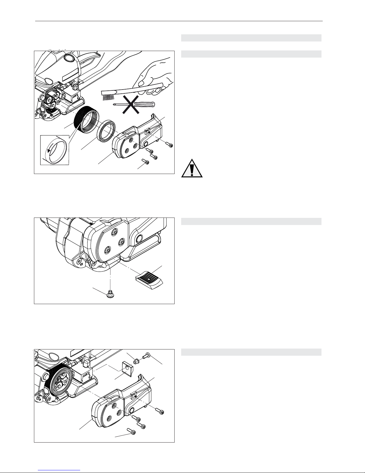
7.1 CLEANING/REPLACING TENSION WHEEL
Removal
– Remove battery from tool.
– Remove four cylinder screws (19/4) and remove strap
stop rear (19/5) and cover (19/3).
– Remove tension wheel (19/1) carefully. Remove ball
bearing (19/2) from tension wheel.
– Clean the tension wheel with compressed air (wear
goggles).
– If the tension wheel teeth are covered with heavy dirt,
they must be carefully cleaned with the wire brush
supplied.
– Check tension wheel for worn teeth. If a few teeth
are broken, replace tension wheel (observe rotating
direction, see arrow)
The tension wheel must not be cleaned
while it is rotating. There is a risk of
breaking teeth!
Installation
– Install the parts in reverse order.
– Grease gear teeth of tension wheel lightly with
Klüber grease GBU Y 131 (Microlube).
5
Fig. 20
2
1
7.2 CLEANING/REPLACING TOOTH PLATE
Removal
– Remove battery from tool.
– Remove pan head screw (20/1). Lift the rocker lever
towards the handle and remove tooth plate (20/2).
– Clean tooth plate with compressed air (wear goggles).
– If the tooth plate teeth are covered with heavy dirt,
they must be carefully cleaned with the wire brush
supplied or a sharp tool.
– Check tooth plate for worn teeth, if necessary replace
tooth plate.
Installation
– Install the parts in reverse order.
– Secure pan head screw (20/1) with Loctite 222.
– The tooth plate (20/2) must be seated so it can move
freely in the rocker.
Fig. 21
3
2
1
6
4
5
7.3 REPLACING KNIFE
Removal
– Remove battery from tool.
– Remove four cylinder screws (21/2) and remove strap
stop rear (21/3) and cover (21/1).
– Release panhead screw (21/4) and remove knife
(21/6) with fl anged bushing (21/5). Replace knife.
Installation
– Install the parts in reverse order.
– Before installing knife, check that the compressing
spring on top of knife is still mounted.
– Secure panhead screw (21/4) with Loctite 222.
Page 25
25
07.09
SIGNODE BXT2
7 WARTUNG UND INSTANDSETZUNG
7.1 SPANNRAD REINIGEN/ERSETZEN
Ausbau
– Akku aus Gerät ziehen.
– Vier Zylinderschrauben (19/4) lösen, Anschlag hinten
(19/5) und Abdeckung /19/3) entfernen.
– Spannrad (19/1) vorsichtig herausziehen. Rillenkugel lager (19/2) von Spannrad abziehen.
– Spannrad mit Druckluft reinigen (Schutzbrille tragen).
– Bei starker Verschmutzung der Verzahnung: Spannrad
vorsichtig mit beiliegender Stahldraht-Bürste reinigen.
– Spannrad auf abgenützte Zähne überprüfen. Sind
mehrere Zähne abgenützt, Spannrad ersetzen (Lauf-
richtung beachten, siehe Pfeil).
Das Spannrad darf nicht rotierend gerei nigt werden. Gefahr von Zähnebruch!
Einbau
– Der Einbau erfolgt in umgekehrter Reihenfolge.
– Innen-Verzahnung des Spannrades leicht mit Klü berfett GBU Y 131 (Microlube) einfetten.
7.2 ZAHNPLATTE REINIGEN/ERSETZEN
Ausbau
– Akku aus Gerät ziehen.
– Flachkopfschraube (20/1) lösen. Wippenhebel gegen
den Traggriff ziehen und Zahnplatte (20/2) entfernen.
– Zahnplatte mit Druckluft reinigen (Schutzbrille tragen).
– Bei starker Verschmutzung der Verzahnung:
Zahnplatte vorsichtig mit beiliegender Stahldraht Bürste oder Reissnadel reinigen.
– Zahnplatte auf abgenützte Zähne überprüfen, nötigen falls ersetzen.
Einbau
– Der Einbau erfolgt in umgekehrter Reihenfolge.
– Flachkopfschraube (20/1) mit Loctite 222 sichern.
– Die Zahnplatte (20/2) muss beweglich in der Wippe
sitzen.
7.3 MESSER ERSETZEN
Ausbau
– Akku aus Gerät ziehen.
– Vier Zylinderschrauben (21/2) lösen, Anschlag hinten
(21/3) und Abdeckung /21/1) entfernen.
– Linsenschraube (21/4) lösen und Messer (21/6) mit
Bundbüchse (21/5) entfernen und ersetzen.
Einbau
– Der Einbau erfolgt in umgekehrter Reihenfolge.
– Vor dem Einbau des Messers prüfen, ob Druckfeder
oberhalb des Messers eingesetzt ist.
– Linsenschraube (21/4) mit Loctite 222 sichern.
7 MANTENIMIENTO Y SERVICIO
7.1 LIMPIEZA/REEMPLAZO DE RUEDA TENSORA
Desmontaje
– Extraiga el acumulador del aparato.
– Extraiga los cuatro tornillos cilíndricos (19/4), y quite el
tope de cinta trasero (19/5) y la cubierta (19/3).
– Extraiga la rueda tensora (19/1) con precaución. Quite
el rodamiento acanalado (19/2) de la rueda tensora.
– Sopletee la rueda tensora (use gafas protectoras).
– Si el engranaje de la rueda tensora se encontrare muy
sucio: límpielo cuidadosamente con el cepillo de
alambres incluido o con una aguja de marcar.
– Revise el desgaste del engranaje; en caso que
algunos dientes se vieren desgastados, reemplace
la rueda tensora.
La rueda tensora no debe ser limpiada
mientras gire: Peligro de rotura de dientes!
Montaje
– El montaje se lleva a cabo invirtiendo los pasos
arriba citados.
– Lubrique el dentado interno de la rueda tensora con
poca grasa GBU Y 131 (Microlube).
7.2 LIMPIEZA/REEMPLAZO DE PLACA ENTADA
Desmontaje
– Extraiga el acumulador del aparato.
– Extraiga el tornillo (20/1). Levante la palanca bascu lante hacia el asa y quite la placa dentada (20/2).
– Sopletee la placa dentada (use gafas protectoras).
– Si el engranaje de la placa dentada se encontrare
muy sucio: límpielo cuidadosamente con el cepillo
de alambres incluido o con una aguja de marcar.
– Revise el estado de desgaste de los dientes en la
placa dentada; reemplácela de ser necesario.
Montaje
– El montaje se lleva a cabo invirtiendo los pasos
arriba citados.
– Asegure el tornillo de cabeza perdida (20/1) con
Loctite 222.
– La placa dentada (20/2) deberá quedar asentada
libremente en la báscula.
7.3 REEMPLAZO DE LA CUCHILLA CORTADORA
Desmontaje
– Extraiga el acumulador del aparato.
– Extraiga los cuatro tornillos cilíndricos (21/2), y quite el
tope de cinta trasero (21/3) y la cubierta (21/1).
– Afl oje el tornillo de cabeza perdida (21/4) y retire la
cuchilla (21/6) con el casquillo (21/5) y reemplácela.
Montaje
– El montaje se lleva a cabo invirtiendo los pasos
arriba citados.
– Antes de montar la cuchilla cerciórese de que el
muelle de compresión se encuentre debidamente
colocado.
– Asegure el tornillo (21/4)con Loctite 222.
Page 26
26
07.09
SIGNODE BXT2
E +
E11
E20
E22
E23
E37
7.4 TROUBLE SHOOTING
If a malfunction occurs, the digital display blinks and
displays error “E” followed by the error number.
FAULT / AVERÍA / STÖRUNG
FAULT:
Rocker lever was operated before the cooling-down
period had elapsed.
ACTION:
– Operate the rocker lever only when the cooling-down
period has elapsed..
FAULT:
The battery used is not the right type.
CAUSE:
– Wrong battery.
ACTION:
– Use the correct battery.
– Restart by removing/replacing the battery.
FAULT:
Battery too hot.
CAUSE:
– Battery temperature above 60°C.
ACTION:
– Let the battery cool down.
– Replace the battery.
FAULT:
Motor overload protection.
CAUSE:
– The motor was overloaded.
ACTION:
– Let the motor cool down.
FAULT:
Battery discharged.
CAUSE:
– The lowest charge limit of the battery has been
reached.
ACTION:
– Charge/replace the battery.
FAULT:
Rocker lever is blocked.
CAUSE:
– Tool blocks when welding.
ACTION:
– Refer to chapter 6.3 or by Service Centre.
For other error numbers not described here,
please contact the Service Centre.
Page 27
27
07.09
SIGNODE BXT2
7.4 BEHEBEN VON STÖRUNGEN
Tritt ein Fehler auf, blinkt die Segment-Anzeige und zeigt
einen Fehler „E“ an, gefolgt von der Fehlernummer.
FEHLER:
Wippenhebel wurde vor Ablauf der Abkühlzeit betätigt.
BEHEBUNG:
– Erst nach Ablauf der Abkühlzeit, Wippenhebel
betätigen.
FEHLER:
Eingesetzter Akku nicht zulässig.
URSACHE:
– Falscher Akku.
BEHEBUNG:
– Korrekter Akku einsetzen.
– Neu starten durch Akku Aus/Einstecken.
FEHLER:
Akku zu heiss.
URSACHE:
– Akku-Temperatur über 60°C.
BEHEBUNG:
– Akku abkühlen lassen.
– Akku ersetzen.
FEHLER:
Überlastschutz des Motors.
URSACHE:
– Der Motor wurde überlastet.
BEHEBUNG:
– Motor abkühlen lassen.
FEHLER:
Akku leer.
URSACHE:
– Unterspannungslimite des Akkus wurde erreicht.
BEHEBUNG:
– Akku laden/ersetzen.
FEHLER:
Wippenhebel blockiert.
URSACHE:
– Gerät blockiert beim Schweissen.
BEHEBUNG:
– Siehe Kapitel 6.3 oder durch Servicestelle.
Bei weiteren hier nicht beschriebenen Fehler nummern, bitte Servicestelle kontaktieren!
7.4 ELIMINACIÓN DE AVERÍAS
Si ocurriera alguna anomalía, el indicador digital parpadeará desplegando “E” (Error) seguido del número
correspondiente.
AVERÍA:
La palanca basculante fue activada antes del periodo de
enfriamiento.
ELIMINACIÓN:
– Actúe la palanca basculante luego del periodo de
enfriamiento.
AVERÍA:
El tipo de acumulador no es el correcto.
CAUSA:
– Acumulador incorrecto.
ELIMINACIÓN:
– Coloque tipo de acumulador correcto.
– Reinicie quitando y reemplazando el acumulador.
AVERÍA:
Acumulador sobrecalentado.
CAUSA:
– Temperatura del acumulador arriba de 60°C.
ELIMINACIÓN:
– Deje enfriar el acumulador.
– Reemplace el acumulador.
AVERÍA:
Protección de sobrecarga del motor.
CAUSA:
– El motor sufrió sobrecarga.
ELIMINACIÓN:
– Deje enfriar el motor.
AVERÍA:
Acumulador descargado.
CAUSA:
– Se alcanzó el límite inferior de tensión del acumulador.
ELIMINACIÓN:
– Cargue/reemplace el acumulador.
AVERÍA:
Palanca basculante bloqueada.
CAUSA:
– El equipo se bloqueó al soldar.
ELIMINACIÓN:
– Vea capítulo 6.3 ó llame al Centro de Servicio.
Para otros errores no citados aquí,
por favor contacte el Centro de Servicio.
Page 28

28
07.09
SIGNODE BXT2
8 WEAR PARTS / RECOMMENDED SPARE PARTS WEAR PARTS / LISTADO DE PARTES
8.1 PARTS LIST BXT2 LIST ADO DE PARTES BXT2
1 428756 Base plate complete, incl. pos. 2-6 Amazón básico compl.,incluye pos. 3-5 1
2
3 428757 Cylinder pin, Ø10x50 Pasador cilíndrico 1
4 428758 Roll pin, Ø6X26 / BN 881 Pasador 1
5 428759 Slide bearing, Ø10/12x10 Cojinete radial 4
6 428760 Slide bearing, Ø8/10x8 Cojinete radial 1
7
9 428880 Tooth plate bottom Place dentada 1
10 428881 Set screw Tornillo prisionero 1
11
12 428761 Bevel wheel with pinion, 15/32 Piñones cónicos 1
13 428882 Free-wheel needle bear., Ø10/14x22 Cañutero 1
14 428762 Ball bearing, Ø15/28x7 Rodamiento ran. 1
15 428763 Spacer disk, Ø20/28x1 Arandela 1
16
17
18 428883 Ball bearing, Ø35/47x7 Rodamiento ran. 3
19 428764 Blocking wheel Bloqueo de rueda 1
20 428765 Planetary wheel, 1st step Engrane planetario 1. Grado 3
21
22
25 428884 Planetary support complete Engrane planetario 1
26
27
28 428885 Spacer, Ø12/24x0.5 Arandela 1
31
32 428766 Flange complete, incl. pos. 35,36 Brida completo, incluye pos. 35,36 1
35 428767 Slide bearing, Ø4/5.5x6 Cojinete radial 1
36 428768 Needle bushing, Ø10/14x15 Cañutero 1
37
38
39 428769 Spacer disk, Ø4/8x0.5 Arandela 1
40 428886 Sicherungsscheibe, Ø3.2 Lock washer 1
41 428887 Cylinder screw, M4x12, 12,9 Tornillo cilíndrico 11
42 428770 Strap guide 13mm Guida del fl eje 13mm 1
43 428771 Counter sunk screw, M4x6 Torn. cabeza. perd. 2
44 428772 Cam disk Disco de leva 1
45 428888 Planetary wheel, 2st step Engrane planetario 2. Grado 3
46 428773 Tension wheel Rueda tensora 1
47
48
50 428774 Rocker complete, incl. pos. 5 Balancín completo, incluye pos. 5 1
51
52
46 428773 Tension wheel Rueda tensora 1
53 428775 Tooth plate
Placa dentada 1
166 428843 Knife Cuchilla 1
222 428865 Battery, 14 V / 2,6 AH Li-Ion Acumulador 14.4V / 2,6 AH Li-Ion 1
222 428866 Battery, 14 V / 2,6 AH Li-Ion, US Acumulador 14.4V / 2,6 AH Li-Ion, US 1
When ordering please indicate part number /
Indique siempre en sus pedidos el N° de artículo y la cantidad requerida.
KEY PART
#
DESCRIPTION QTY
When ordering please indicate part number /
Indique siempre en sus pedidos el N° de artículo y la cantidad requerida.
KEY PART
#
DESCRIPTION QTY
When ordering please indicate part number /
Indique siempre en sus pedidos el N° de artículo y la cantidad requerida.
KEY PART
#
DESCRIPTION QTY
Page 29

29
07.09
SIGNODE BXT2
53 428775 Tooth plate Placa dentada 1
54 428776 Pan head screw Tornillo 1
55 428777 Strap stop, front 13mm Limitador del fl eje 13mm 1
56
57
59 428778 Pawl shaft
Trinquete 1
60 428779 Pawl wheel Bloqueo de rueda 2
61 428889 Retaining ring, Ø5 Arandela de fi jación 1
62
64 428780 Bolt Tornillo 1
65 428781 Blocking pawl Trinquete 1
66 428782 Retaining ring, Ø8 Arandela de fi jación 2
67
68
70 428783 Bolt Tornillo 1
71 428784 Spacer disk, Ø5/10x0.2 Arandela 1
72 428785 Reset cam Cuva 1
73 428786 Set screw, M4x10 Tornillo prisionero 1
74 428787 Retaining ring, Ø4 Arandela de fi jación 6
75 428788 Support micro switch Ayuda 1
76 428890 Panhead screw, M4x10 Tornillo 4
77 428789 Welding cables Cables de la soldadura 1
78
79
81 428790 Compression spring Resorte opresor 1
82 428791 Ball, Ø8 Bola 1
83 428792 Compression spring Resorte opresor 1
84 428793 Balll, Ø9 Bola 1
85 428794 Set screw, M12x10 Tornillo prisionero 1
86 428795 Set screw, M8x6 , Tufl ok Tornillo prisionero 1
87
88
89 428796 Rocker lever complete Palanca de balacín completo 1
90 428797 Toothed lever Palanca dentada 1
91
92
95 428798 Motor complete Motor completo 1
96 428799 Motor support complete Ayuda del motor completo 1
97
98
99 428800 Counter sunk screw, M3x8 Torn. cabeza. perd. 6
100 428801 Spacer disk, Ø4/8x0.1 Arandela 3
101 428802 Shoulder screw, M5 Tornillo de hombro 2
102 428803 Cylinder screw, M4x30 Tornillo cilíndrico 1
103 428804 Cables tensioning Tensir de los cables 1
104 428805 Panhead screw, M2x10
Tornillo 1
105
106
108 428806 Ball bearing, Ø30/37x4 Rodamiento ran. 1
109 428807 Excentric cam Árbol de excéntricos 1
110 428808 Planetary wheel, 3st step Engrane planetario 3. Grado 3
111 428809 Spacer disk, Ø12/24x0.2 Arandela 1
112 428810 Carrier complete 2st step 1
113
114
116 428811 Planetary wheel, 2st step Engrane planetario 2. Grado 6
117 428812 Spacer disk, Ø6/12x0.2 Arandela 2
118 428813 Carrier complete 1st step Portador completo 1. Grado 1
119
120
124 428814 Ring Anillo 1
125 428815 Cover motor support Envoltura del motor compl. 1
127 428891 Belt wheel complete Rueda de la correa 1
128
129
130 428816 Starting disk Comenzar el disco 1
131 428817 Ball bearing, Ø15/24x5 Rodamiento ran. 2
132 428818 Bevel wheel complete Piñones cónicos completo 1
133
134
135 428819 Spacer ring, Ø15/18x2.9 Arandela 1
136 428820 External retaining ring, Ø15 Arandela de fi jación 1
137
138
140 428821 Switching cam Leva de la conmutación 1
141 428822 Spacer, Ø5/10x0.1 Arandela 2
142 428823 Bolt Tornillo 1
143 428824 Bolt Tornillo 1
KEY PART
#
DESCRIPTION QTY KEY PART
#
DESCRIPTION QTY
Page 30

30
07.09
SIGNODE BXT2
KEY PART
#
DESCRIPTION QTY KEY PART
#
DESCRIPTION QTY
144 428825 Bolt
Tornillo 1
145
146 428826 Screwed shaft Eje atornillado 1
147 428827 Lower linkage Baje el acoplamiento 1
148 428828 Upper linkage Acoplamiento superior 1
149 428829 Compression spring, Ø9.8x3x27.4
Resorte opresor 1
150
153 428830 Swivel bearing Cojinete del eslabón giratorio 1
154 428831 Ball bearing, Ø7/19x6 Rodamiento ran. 2
155 428832 Excentric shaft Árbol de excéntricos 1
156 428833 Spacer disk, Ø10/22x0.5 Arandela 2
157 428834 Needle bearing, Ø10/17x12 Cañutero 1
158 428835 Welding shoe Zapato de la soldadura 1
159 428836 Ball, Ø5 Bola 4
160 428837 Supporting disk Disco 1
161 428838 Pinion Piñón 1
162 428839 Toothed belt, 158-2MGT-9 Correa dentada 1
163 428840 Washer Arandela 1
164 428841 Cylinder screw, M4x8 Tornillo cilíndrico 1
165 428842 Bolt Tornillo 1
166 428843 Knife Cuchilla 1
167 428892 Flanged bushing Forrar ensanchado 1
168 428893 Compression spring, Ø4.2x0.8x11 Resorte opresor 3
169 428844 Compression spring, Ø4.1x0.8x24 Resorte opresor 1
170
172 428894 Lever strap guide complete Palanca completo 1
175 428845 Side cover Cubierta lateral 1
176 428846 Bearing bolt Perno del cojinete 1
177 428847 Rear inner guide 16mm Guía interna 16mm 1
178 428848 Rear inner guide 13mm Guía interna 13mm 1
179
180
181 428849 Strap guide rear 13mm Guía del fl eje 13mm 1
182 428850 Panhead screw, M4x6 Tornillo 1
183 428851 Gear cover, Alu Cubierta del engranaje 1
184
186 428879 Housing parts, black Carcaza exterior 1
188
189 428852 Type plate, 10x45mm Etiqueta 1
190
191 428895 Motor cover complete
Envoltura del motor completo 1
192 428853 Name plate, 10x45mm Etiqueta 1
193
194
197 428854 PT-Screw, KA 35x20
Tornillo-PT 9
198 428855 Printed circuit board Carta electrica 1
199 428856 Protection cover pcb Cubierta de la protección 1
200 428857 PT-Screw, KA 22x6 Tornillo-PT 2
201 428858 Intermediate cable Cable intermedio 1
202 428859 Signal cable Cable de señal 1
203 428860 Gasket, 10x10x15 Junta 2
204 428861 Protection plate Placa de protección 1
205 428862 Switch button Botón 1
206 428863 Compression spring, Ø5x0.6x14 Resorte opresor 1
207
208
209
212 428864 Printed circuit board complete Carta electrica 1
213
214
215 428896 Contact plate 14.4 V Placa del contacto 14.4 V 1
216
217
222 428865 Battery 14.4V / 2.6 Ah Li-Ion Acumulador 14.4V 1
222 428866 Battery 14.4V / 2.6 Ah Li-Ion, US Acumulador 14.4V, US 1
223
224 428867 Battery charger AL 1860CV-EU Cargador rápido AL 1860CV-EU 1
224 428868 Battery charger AL 1860CV-US Cargador rápido AL 1860CV-US 1
224 428869 Battery charger AL 1860CV-JP Cargador rápido AL 1860CV-JP 1
225
226
227 428870 Wire brush / 21242 Cepillo metálico 1
228 428897 Screw driver, crosstip Destornillador 1
229 428898 Angle-wrench, hexagon Ángulo-llave, hexágono 1
230
231
232
233
Page 31

31
07.09
SIGNODE BXT2
KEY PART
#
DESCRIPTION QTY
234 428871 Option: protection plate-set Opcion: placa protectora
235
236 428872 Counter sunk screw, M4x6 Tornillo 5
237
239 428873 Option: Protection cover Opcion: cubierta de la protección
240
241 428899 PT-Screw, KA 35x30
Tornillo-PT 2
242 428900 PT-Screw, KA 35x14 Tornillo-PT 2
243
245 428901 Option: suspension bow-set Opcion: juego de gancho
246
247 428874 Cylinder screw, M4x20 Torn. cabeza. perd. 3
248 428875 Cylinder screw, M5x16 Torn. cabeza. perd. 2
249
251 428876 Option: Strap guide set 9mm Opcion: Guida del fl eje 9mm
257
258 Option: Power supply connection Opcion: Conexión de alimentación
259 428877 Mains Connector 230V EU Conectador de las cañerías 230V EU 1
259 428878 Mains Connector 115V US Conectador de las cañerías 115V US 1
260
When ordering please indicate part number
Indique siempre en sus pedidos el N° de artículo y la cantidad requerida.
Bold = Recommended spare parts
Negrilla = Partes recommendadas
Page 32
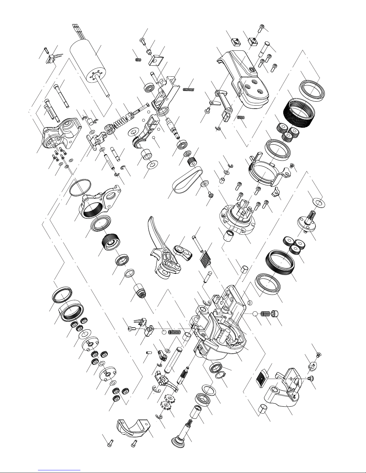
32
07.09
108
109
110
111
112
116
117
118
117
116
124
125
130
127
131
132
135
41*
183
75
103
76*
82
81
5
73*
61
60
59
71
72
74
66
65
64
136
15
14
13
12
131
1
3
4
5
66
70
89
90
10*
9
6
84
83
85
86*
5
50
54*
43*
55
53
18
19
20
25
28
36
35
39
40
32
41*
18
46
45
18
44
43*
42
100
99*
96
104*
103
101*
95
102*
74
41*
74
74
74
74
41*
176
175
178
177
168
172
181
182*
164*
163
162
160
154
161
155
169
153
166
167
76*
168
154
165*
146
147
149
159
158
156
157
148
144
140
141
142
143
26.06.09 wr/hp
OR-T 250 1832-002-023/1.1
Fig. A
*
Loctite 222
BXT2
Page 33
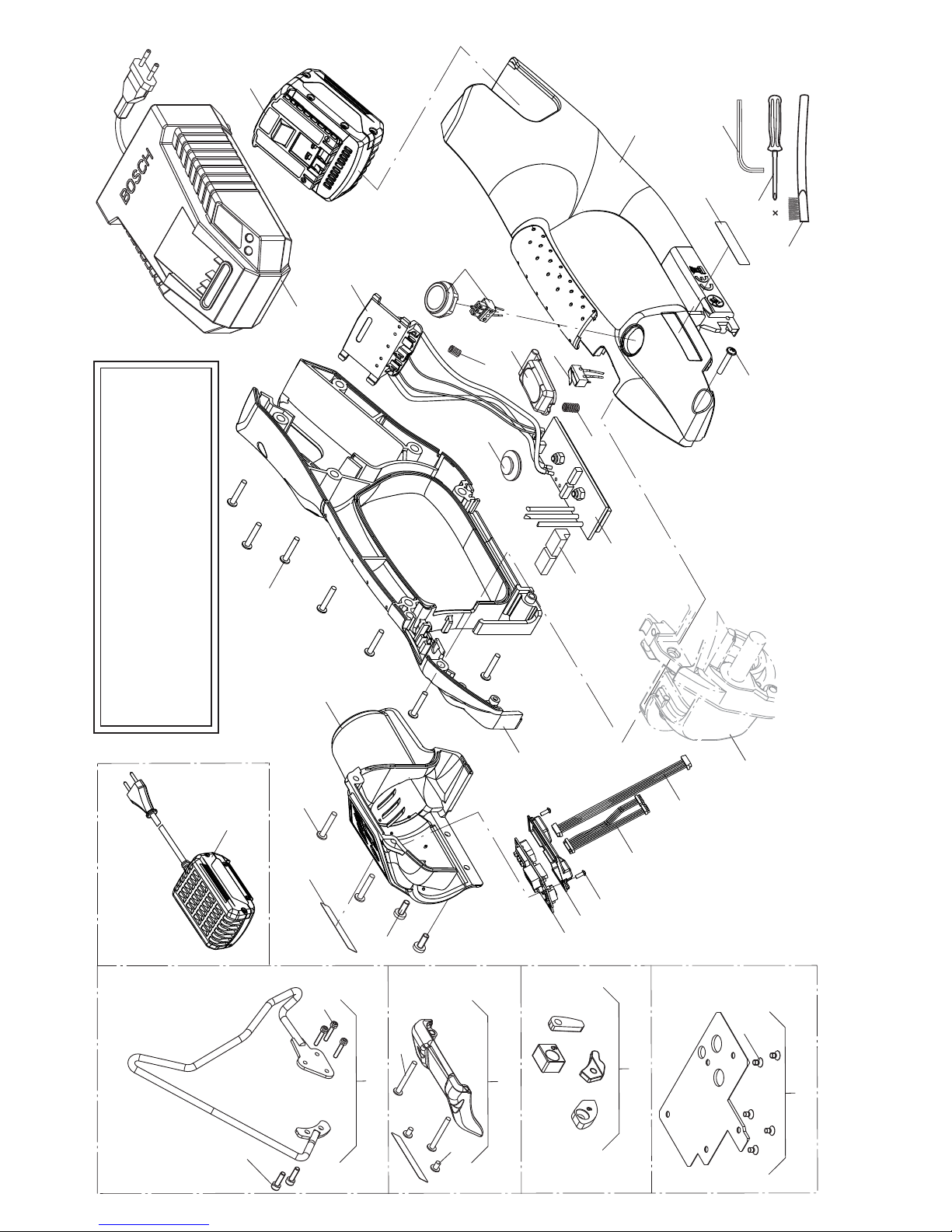
33
07.09
229
189
227
228
197
186
222
197
206
205
77
168
212
203
204
186
Fig. A/1
202
201
200
199
198
191
197
192
76
224
245
239
(247)
(248)
(241)
251
234
(236)
Options
259
77
215
26.06.09 wr/hp
BXT2 1832-002-023/1.1
Fig. B
(242)
WARNING
Inspect all parts daily and replace them if they
are worn or broken. Failure to do this can affect
a product’s operation and could result in
serious personal injury.
Page 34

34
07.09
SIGNODE BXT2
NOTIZEN
Page 35

35
07.09
SIGNODE BXT2
NOTES NOTES
Page 36
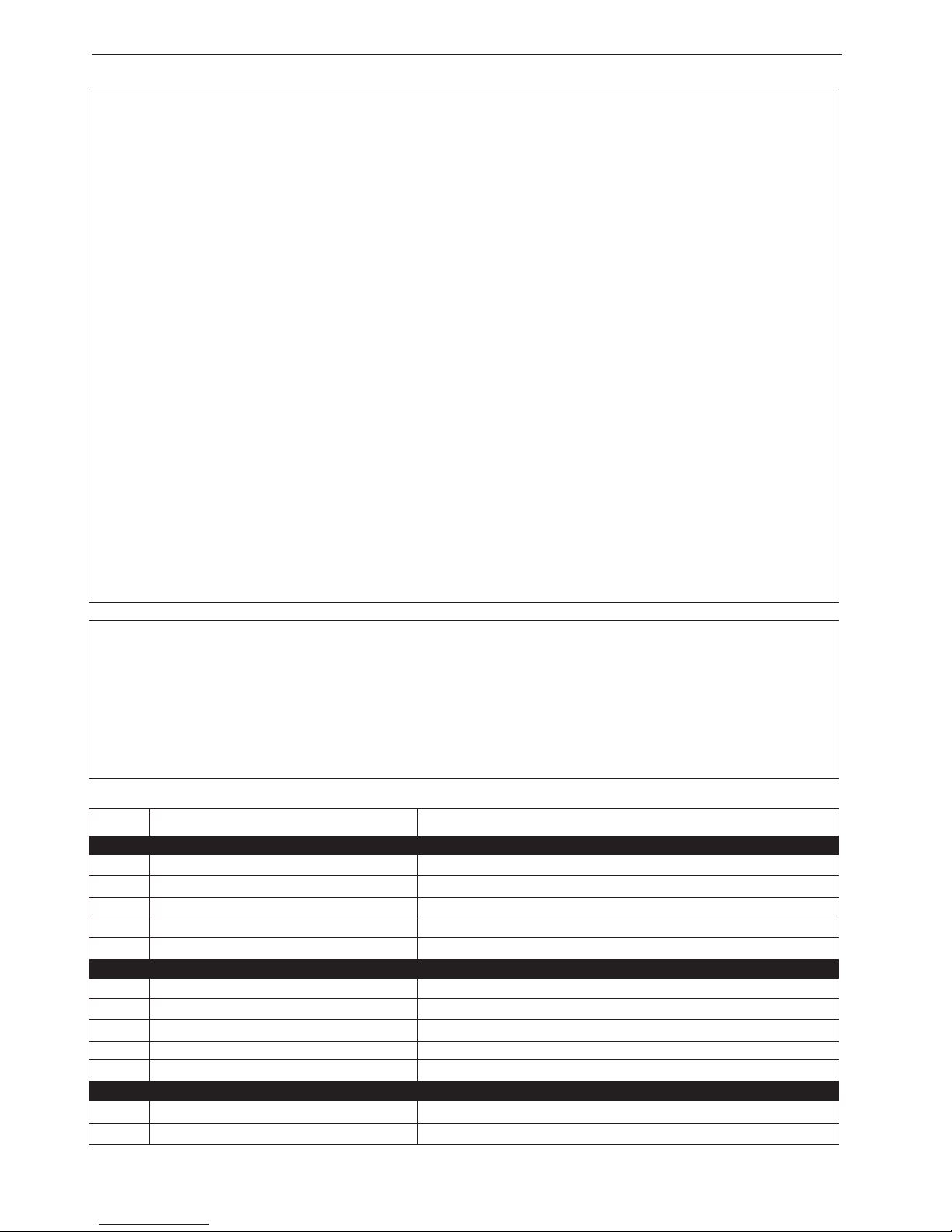
36
07.09
SIGNODE BXT2
SIGNODE
NEW TOOL WARRANTY
Signode Engineered Products Warrants that a new Signode strapping tool will operate per functional
specifi cations for a period of sixty (60) days after the date of shipment to the owner’s place of business. Normal
wearing parts, as outlined in the Operation, Parts & Safety manual, are covered by a thirty (30) day warranty
unless, in Signode’s judgement, these parts have been subjected to abnormal or extreme usage. Signode’s sole
liability hereunder will be to repair or replace, without charge, F.O.B. Signode’s Glenview,Illinois plant, any tool
which proves to not operate per functional specifi cations within the stated period. Signode reserves the right to
replace any tool which proves not to operate per functional specifi cations with a new or like-new tool of the same
model if in Signode’s judgement such replacement is appropriate.
Any new replacement tool provided to an owner will carry a full sixty (60) day warranty. Any warranty
repaired tool or like-new replacement tool will carry a warranty for the balance of the time remaining on the
initial sixty (60) day warranty. This warranty will be extended to compensate for the time the tool is in Signode’s
possession for warranty repairs.
This warranty is void as to any tool which has been: (I) subjected to mis-use, misapplication, accident,
damage, or repaired with other than genuine Signode replacement parts, (II) improperly maintained, or adjusted,
or damaged in transit or handling; (III) used with improperly fi ltered, unlubricated air or improper strapping material,
(IV) in Signode’s opinion, altered or repaired in a way that affects or detracts from the performance of the tool.
SIGNODE MAKES NO WARRANTY, EXPRESSED OR IMPLIED, RELATING TO MERCHANTA-BILITY, FITNESS
OR OTHERWISE EXCEPT AS STATED ABOVE AND SIGNODE’S LIABILITY AS ASSUMED ABOVE IS IN
LIEU OF ALL OTHERS ARISING OUT OF OR IN CONNECTION WITH THE USE AND PERFORMANCE OF
THE TOOL. IT IS EXPRESSLY UNDERSTOOD THAT SIGNODE SHALL IN NO EVENT BE LIABLE FOR ANY
INDIRECT OR CONSEQUENTIAL DAMAGES INCLUDING, BUT NOT LIMITED TO, DAMAGES WHICH MAY
ARISE FROM LOSS OF ANTICIPATED PROFITS OR PRODUCTION, SPOILAGE OF MATERIALS, INCREASED
COSTS OF OPERATION OR OTHERWISE.
Considerable effort has be made to ensure that this product conforms to our high quality standards.
However, should you experience any diffi culties, please contact your Sales Representative providing
samples and the manufacturing code specifi ed on the tool.
Thank you for your help.
SIGNODE ENGINEERED PRODUCTS
Hand Tool Division
3620 W. Lake Avenue, Glenview, Illinois 60025
PART # DESCRIPTION AREA OF USE
LUBRICANTS
008556 LS-1236 AIR LINE OIL AIR MOTORS, AIR VALVES
422792 WHITE LUBRIPLATE GR-132 GREASE PNEUMATIC PARTS, AIR CYLIN., AIR VALVES, O-RINGS
422793 BLACK LUBRIPLATE 3000W GREASE MOVING EXTERNAL PARTS, JAWS, LINKS
425239 RED MOBILITH SHC 007 GREASE INTERNAL GEARS
432322 EP ACCROLUBE GREASE HIGH FRICTION CONTACT PARTS
ADHESIVES
274111 LOCTITE #380 BLACK MAX PERMANENT, FLAT SURFACE PART CONTACT
422794 LOCTITE #222 PURPLE LOW STRENGTH, SCREWS 1/4“ (6MM) OR SMALLER SIZES
422795 LOCTITE #242 BLUE MEDIUM STRENGTH SCREWS 5/16“ (8MM) OR LARGER
422796 LOCTITE #271 RED HIGH STRENGTH, SEMI-PERMANENT SCREWS APPLI.
422797 LOCTITE #609 GREEN PERMANENT, CURVED SURFACE PART CONTACT
CLEANING BRUSHES
023963 SMALL BRUSH FEEDWHEEL & GRIPPER TEETH
269589 LARGE BRUSH FEEDWHEEL & GRIPPER TEETH
 Loading...