

Page 1
AMPT-12
POWERED COMBINATION STRAPPING TOOL
SIGNODE !
! 3620 WEST LAKE AVENUE !!!! GLENVIEW, ILLINOIS 60025
!!
Page 2
READ THESE INSTRUCTIONS CAREFULLY.
FAILURE TO FOLLOW THESE INSTRUCTIONS CAN RESULT IN SEVERE PERSONAL INJURY.
GENERAL SAFETY CONSIDERATIONS
1. STRAP BREAKAGE HAZARD.
Improper operation of the tool or sharp corners on the load can result in strap
breakage during tensioning, which could result in the following:
!!!! A sudden loss of balance causing you to fall.
!!!! Both tool and strap flying violently towards your face.
Failure to place the strap properly around the load or an unstable or shifted load could result
in a sudden loss of strap tension during tensioning. This could result in a sudden loss of
balance causing you to fall.
Read the tool's operating instructions. If the load corners are sharp use edge protectors.
Place the strap correctly around a properly positioned load.
!!!! Positioning yourself in-line with the strap, during tensioning and sealing, can result in
severe personal injury from flying strap or tool. When tensioning or sealing, position
yourself to one side of the strap and keep all bystanders away.
!!!! Using strap not recommended for this tool can result in strap breakage during tensioning.
Use the correct Signode products for your application.
2. TRAINING.
This tool must not be used by persons not properly trained in its use. Be certain that you
receive proper training from your employer. If you have any questions contact your Signode
Representative.
3. EYE INJURY HAZARD.
Failure to wear safety glasses with side shields can result in severe eye injury or
blindness. Always wear safety glasses with side shields which conform to ANSI
Standard Z87.1 or EN 166.
4. FALL HAZARD.
Maintaining improper footing and/or balance when operating the tool can cause you to fall. Do
not use the tool when you are in an awkward position.
5. CUT HAZARD.
Handling strap or sharp parts could result in cut hands or fingers. Wear protective
gloves.
2
Page 3
6. TOOL CARE.
Take good care of the tool. Inspect and clean it daily, lubricate it weekly and adjust when
necessary. Replace any worn or broken parts.
7. WORK AREA.
Keep work areas uncluttered and well lighted.
Several types of strap can be used with this tool. Use the correct Signode products for your
application. If you need help contact your Signode Representative.
SAFETY PROCEDURES FOR TOOL OPERATION
1. Before using this tool, read its Operation and Safety instructions.
!!!! Do not exceed the operating air pressures stated elsewhere in the manual.
!!!! Use Signode's approved filter-regulator-lubricator unit (P-173111).
!!!! Never operate a pneumatic tool with a bottled air or gas source.
!!!! For tension adjustments, follow instructions in this manual. For all other adjustments,
repairs or cleaning of the tool, disconnect air supply.
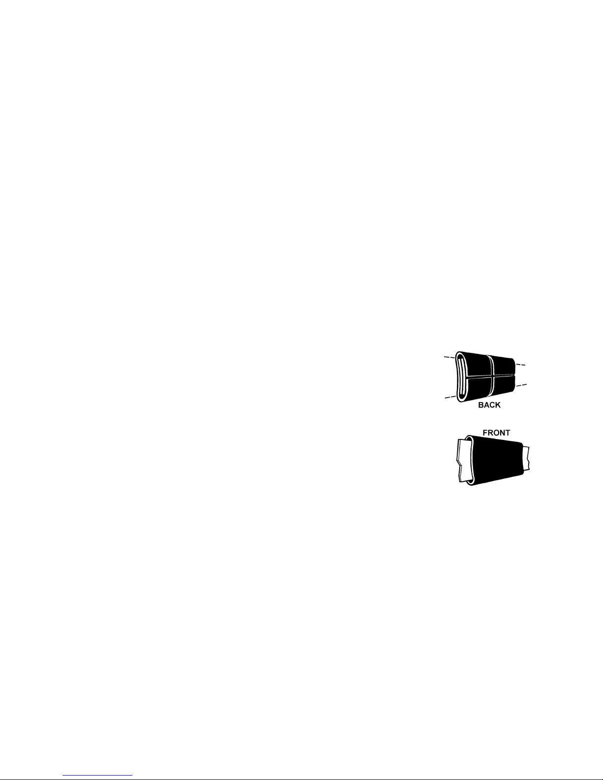
!!!! This tool has a crimp type sealer. A properly made joint will appear as
shown in the illustration. If the joint does not appear as shown, then the
operator must proceed as follows:
A. Insure that the tools operating instructions are
being followed before applying another strap.
B. Cut the strap off and apply another.
If the joint still does not appear as shown, then inspect the tool for worn and/or
damaged parts. Replace tool parts as needed. NEVER HANDLE OR SHIP ANY
LOAD WITH IMPROPERLY FORMED JOINTS. Misformed joints may not secure
the load and could cause serious injury.
!!!! Tuck strap end back into the dispenser when not in use.
CUTTING TENSIONED STRAP
Use only cutters designed for cutting strap; never use claw hammers, crowbars, chisels, axes or
similar tools. Such tools will cause the strap to fly apart with hazardous force. Before using any
Signode product, read its Operation and Safety Manual.
3
Page 4
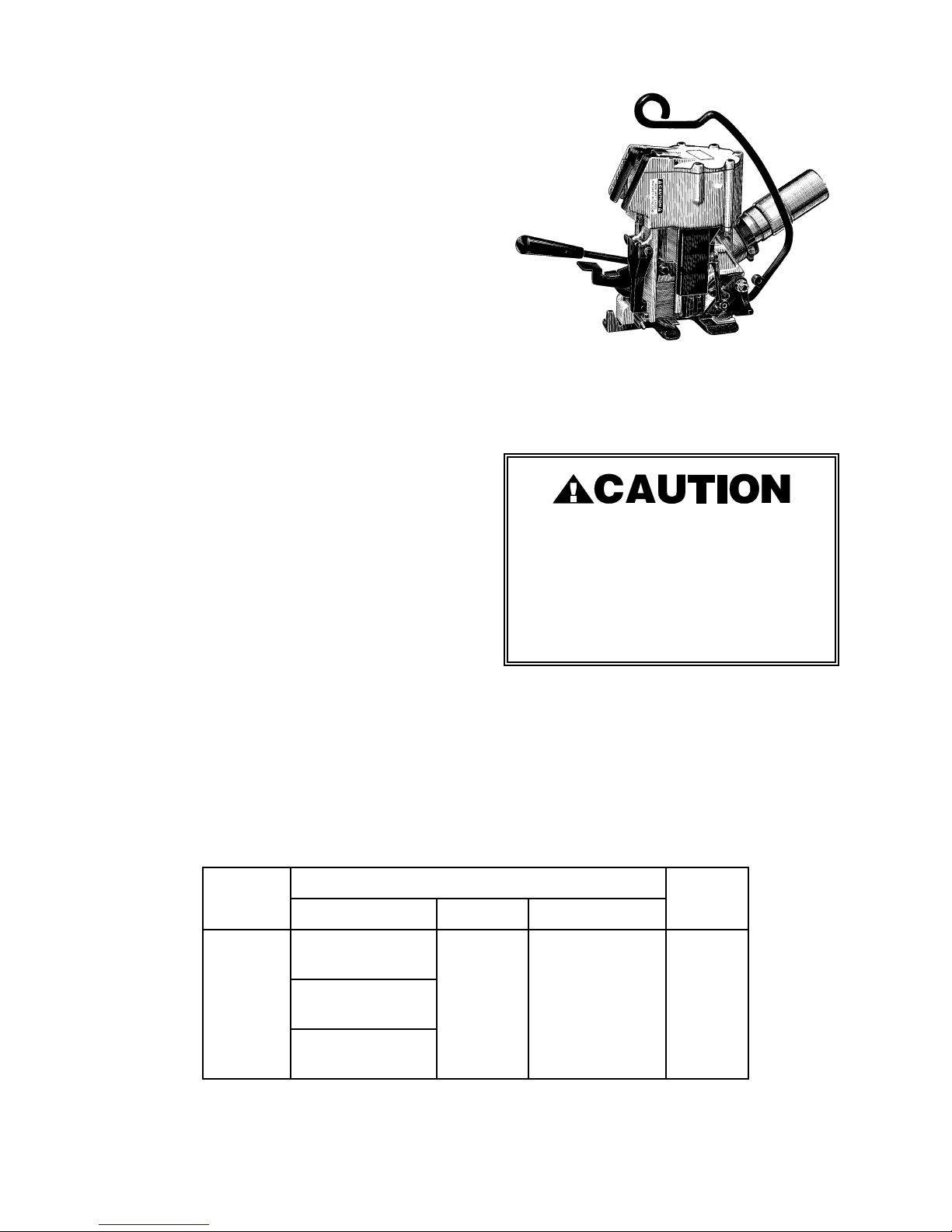
TABLE OF CONTENTS
General Safety Instructions 2
Specifications 4
Pneumatic Information 5
Strap Tension 8
Loading Seals 8
Cutter Adjustment 8
Page
Operating Instructions 9
Joint Inspection 10
Tool:
Parts List & Views 11
Disassembly/Assembly 17
Gear Housing
Parts List & View 20
Disassembly/Assembly 20
Air Motor I8R36:
Parts List & View 22
Disassembly/Assembly 24
Troubleshooting 25
Maintenance 33
Declaration of Conformity 35
AMPT-12
Part No. 422910
DO NOT USE AMPT-12
WITH STEEL STRAPPING
Using strap not recommended for this
tool can result in strap breakage,
improper joint formation and tool
damage.
MODEL
1822,1818,1816
AMPT-12
508,506,504,502
SPECIFICATIONS
STRAP
TYPE WIDTH THICKNESS
Tenax
Contrax
818,816,814
Dymax
1/2"
(12mm)
4
.015" to .030"
(0.4 - 0.8mm)
SEAL
50ASD
Page 5

PNEUMATIC INFORMATION
AIR PRESSURE REQUIREMENTS
The AMPT-12 tools are designed to operate
at air pressures ranging between 65 and 90
psig (4.5 - 6.2 Bar).
AIR SUPPLY INSTALLATION
If compressor has a good dryer unit, use
black pickled pipe. When a dryer unit is not
installed, use galvanized or copper pipe.
To perform reliably, a pneumatic tool
requires a continuous source of clean, waterfree air at adequate pressure.
Never operate this tool using a
bottled air or gas source.
A filter-regulator-lubricator unit (Signode Part
No. 173111) must be installed as close to the
air tool as possible, preferably within 10 feet.
It should be placed in a convenient location
where it can easily be drained, adjusted, and
filled with oil. The air hose
must have at least a 1/4" I.D. A quickconnect press-on socket is installed on the
stress spring end of the hose for convenient
hookup to the air tool.
Filter and lubricator bowls are made of
polycarbonate material. Do not install where
bowls may be exposed to materials incompatible with polycarbonate. Certain oils,
solvents, and chemicals or their fumes can
weaken these bowls and possibly cause
them to burst. Clean only with warm water.
A cut-off valve placed ahead of the filter will
be useful when cleaning the filter or
replenishing the lubricator.
5
Page 6

PNEUMATIC INFORMATION, Continued
MOISTURE
Moisture is always present in air lines due to
condensation within the lines as the air
cools. Steps must be taken to remove this
moisture and to keep it from the air tool.
This is because water tends to wash away
lubricants and cause corrosion, sticking and
failure of internal parts.
The main line should be pitched so the far
end terminates in a water leg. Branch lines
are taken from the top of the main, never off
the bottom. Every branch should have a
water leg at its lowest point, with a drain
cock which is drained daily.
If these precautions are taken and water is
still present, an after cooler and a moisture
separator are required between the compressor and the air receiver tank. A large air line
separator can be installed in the air tool line,
but precautions must be taken to insure that
it will be drained daily, before the air tool is
operated.
LUBRICATION
The air motor must be properly lubricated.
This is achieved by keeping the air line
lubricator filled with oil and correctly
adjusted. Without proper lubrication, the
motor will become sticky and the tool will
give low and erratic tension and be difficult
to release from the strap.
Install the lubricator as close to the air tool
as possible. The arrow on the lubricator's
top surface must point in the direction of air
flow.
For proper operation, oil must drop through
the lubricator sight glass at a rate of 1 to 4
drops per minute. This rate is checked while
the air tool is running free. Only 20% of this
oil is actually delivered to the tool. The
remaining oil drops back into the oil
reservoir. The unit is factory set and should
require no adjustment. If an adjustment is
required, the adjusting screw on top of the
lubricator may be turned as marked to
reduce or increase the flow of oil.
Water in air lines is a constant threat to the
proper operation of air tools. Even near
freezing operating conditions, a good
refrigerant type dryer is essential. A good
dryer will remove 95% or more of water right
at the compressor. The remaining moisture
is removed at the water leg in the piping
system or in the filter portion of the F-L-R
(Part No. 173111) unit.
NOTE: Additional information is available in
the Signode publication, "Air Supply Manual"
(Part No. 186038). If you have any questions,
contact your local Signode Representative.
The correct grade of oil must be used in the
lubricator; too heavy an oil will not provide
sufficient lubrication and will cause sticking
and sluggish operation of the air tool.
Recommended oils are any good grade of
rust and oxidation inhibiting oil with a
viscosity of 80-120 S.U.S. at 100 degrees
Fahrenheit. (0.15 to 0.25 cm2 /sec. at 38
degrees Celsius), such as:
Non Fluid Oil Co., grade #LS-1236
Signode oil - Part No. 008556
If necessary, use SAE #5 or SAE #10 nondetergent, cut 1 to 1 with kerosene.
NOTE: Some oils contain anti-wear additives
which may disable the air motor. Be certain
to use recommended oil.
Several drops of lubricator oil added to the
inlet of the air motor or into the air line each
day will help insure good operation. A
noticeable reduction of air motor
performance can usually be corrected by
squirting a few drops of oil into the air line.
6
Page 7

AIR CONSUMPTION
COLD WEATHER OPERATION
Air consumption in cubic feet per minute
(cfm) for the AMPT-12 can be calculated as
follows:
cfm = (a) x (b) x (0.20)
a = Number of straps applied per minute.
b = Number of seconds motor is on per
strap during tensioning, from start to
deceleration to stall including stall
time while making joint when.
0.20 = AMPT-12 efficiency ratio.
Example Calculation:
Peak strapping load: 4 straps/min. so a = 4
Air motor run time: 5 sec./strap, so b = 5
AMPT-12 efficiency ratio is 0.20
(a)x(b)x(0.20) 6
Air pressure is assumed to be 90 psig (6.2
Bar) with recommended size and length of air
hose. Volume of air is at room temperature
and sea level pressure, or so-called "free air"
conditions. For more detailed information
about air supply systems refer to Signode
manual Part No. 186038.
6 4x5x0.20 = 4 cubic ft/min.
66
If a tool does not operate satisfactorily in
freezing temperatures, certain steps can
correct the problem. The following steps can
be taken to improve cold weather operation
of the tool:
a. An air line dryer adjacent to the
compressor.
b. Use lubricant recommended by Signode.
Signode has tested the use of antifreezes, none work well in air tools; the
tool will gum up when anti-freezes are
introduced and will not function properly.
The best lubricant for freezing weather is
the 1 to 1 oil and kerosene combination.
c. If possible, run the air supply line to a
indoor located Filter-RegulatorLubricator or relocate the F-L-R to a
warmer operating area.
7
Page 8
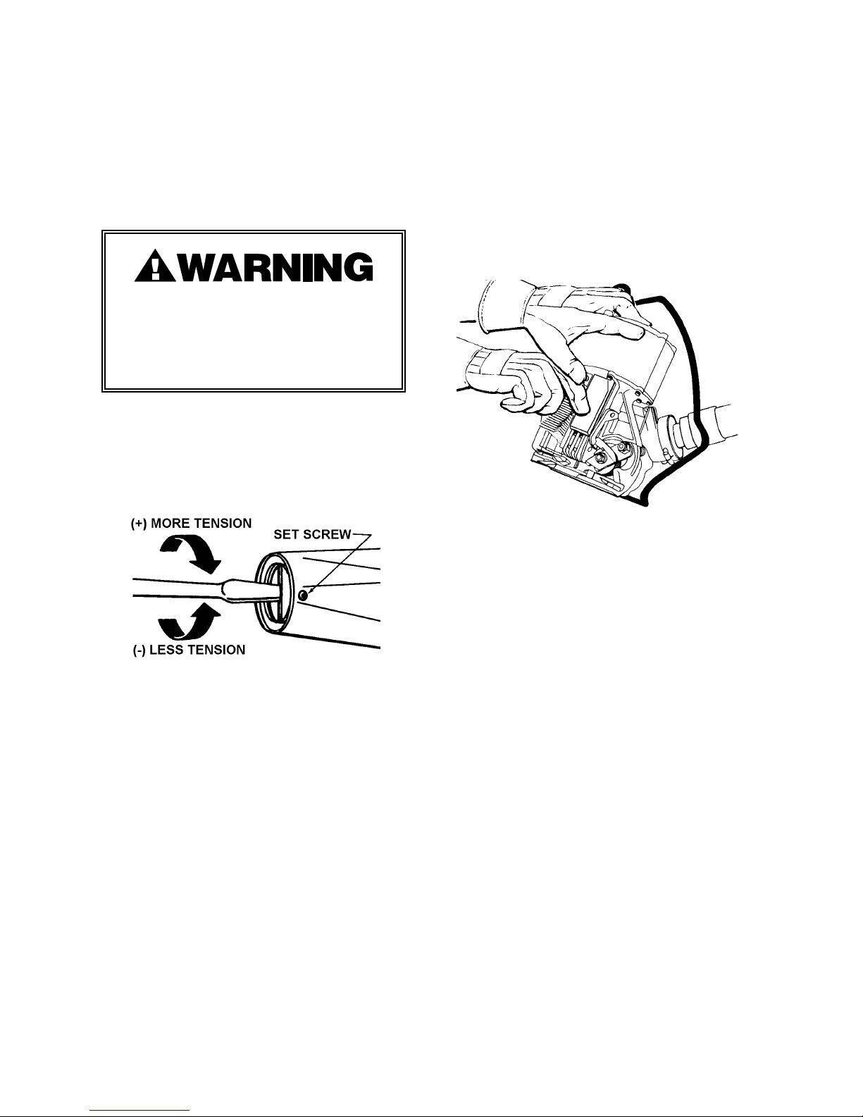
STRAP TENSION
LOADING SEALS
The AMPT-12 tools are factory tested to
ensure that at least 350 lbs. (1554N) of
tension is drawn at 90 psig (6.2 Bar).
NOTE: Make sure the input air pressure to
the tool is set between 65 and 90 psig.
Strap breakage hazard. Strap can break
while tension is being increased. Stand
to one side of the strap as it is being
tensioned. Failure to do so could result
in personal injury.
To adjust the AMPT-58 strap tension, use the
following instrcutions:
1. Loosen the set screw on the side of the
air motor.
To load seals, raise the seal pad assembly
and insert a stack of seals inside the seal
magazine. Release the seal pad. Activate
the sealing mechanism by depressing then
releasing the sealing lever. A seal will be
ejected into the sealing jaws. An extension
on the seal pad closes the top strap loading
slot as a reminder to add seals.
2. Turn the pressure adjustment screw in
increments of 1/8 turns clockwise to
decrease strap tension and counterclockwise to increase strap tension.
3. Turn the adjustment screw until the
desired tension level has been reached.
4. When a satisfactory tension level has
been reached tighten the set screw.
The tool is now set to operate at a given air
pressure in combination with a particular
strap size. Any change in air pressure or
strap size could result in unsatisfactory tool
performance or strap breakage.
CUTTER ADJUSTMENT
If the cutter on the tool does not cut properly,
loosen the shoulder bolt (39) and cap screw
(42), and adjust set screw (44) to remove
clearance between the cutter blade and the
cutter block. Adjust with the jaws in the
down position. Do not over tighten as the
sealing mechanism can be bound by this
adjustment. When adjustment has been
made, retighten the shoulder bolt and cap
screw.
8
Page 9
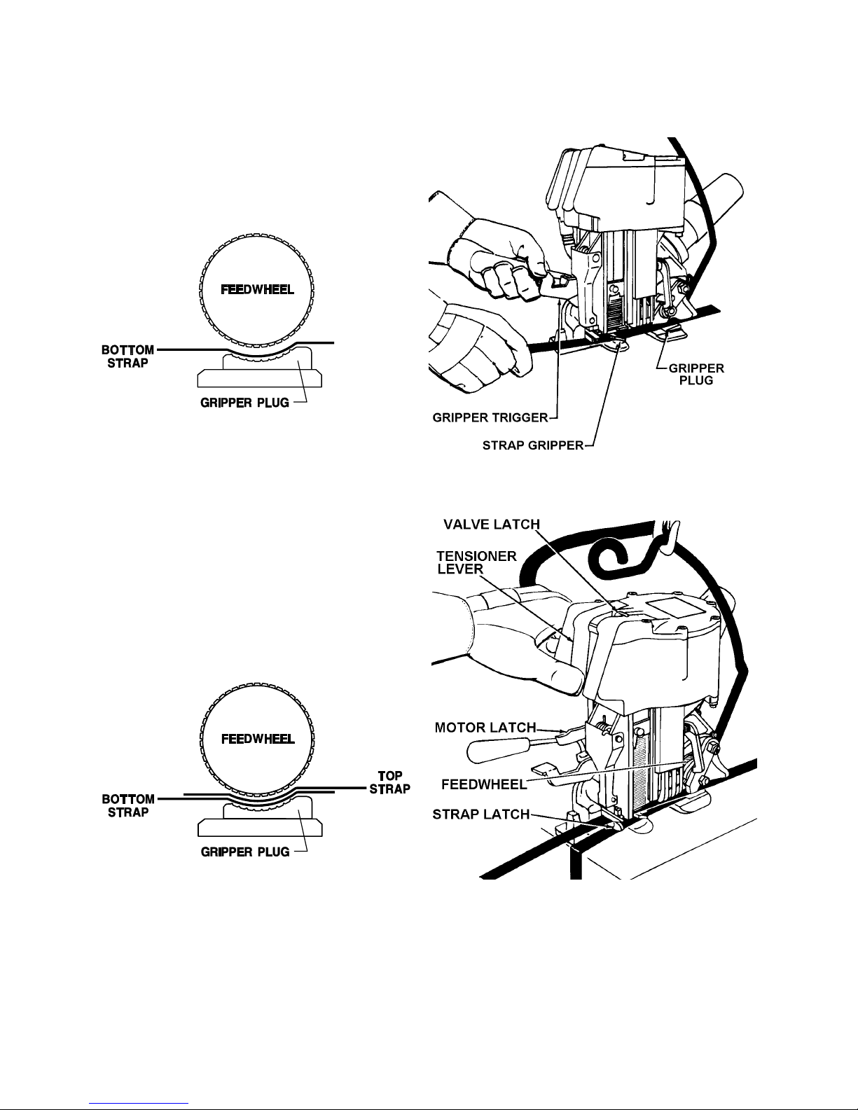
OPERATING INSTRUCTIONS
1. Encircle the package with strap and insert
the bottom end under feedwheel so that it
extends at least 1/2" (12mm) beyond the
gripper plug. Depress the gripper trigger to
actuate the strap gripper.
2. Insert the top strap between the feedwheel
and the gripper plug and insert it into the slot
of the strap latch. Pull excess slack from the
strap. Make sure you are not standing in line
with the strap and press the tensioner lever
all the way down. It will lock in place. The
feedwheel will engage automatically and the
tool will begin tensioning. Should it become
necessary to stop the tensioning cycle, press
the valve latch forward.
NOTE: The feedwheel can be lowered manually, without starting the motor, by pressing the
motor latch. To start the motor, press the tensioner lever.
9
Page 10

OPERATING INSTRUCTIONS, Continued
3. The motor will stall when the pre-set tension
level has been reached. Press the sealer
lever all the way down, then release. Do not
hold tensioner lever down while pressing the
sealer lever as the tensioning lever will be
released automatically. The tool will
automatically seal the straps together, cut off
the top strap and eject a new seal into the
jaws. Inspect the joint to make sure the tool
has properly crimped the seal.
4. After the tool has sealed and the sealing
mechanism retracts, the feedwheel will
automatically raise off the straps. Swing the
rear of the tool away from the completed tie
to free the tool.
5. If the resulting tension level is not
satisfactory for your strapping needs, then proceed to adjust
the tension as described earlier in this manual.
JOINT INSPECTION
This tool has a crimp type sealer. A properly made joint will
appear as shown in the illustration. If the joint does not
appear as shown, then the operator must proceed as follows:
1. Insure that the tools operating instructions are being
followed before applying another strap.
2. Cut the strap off and apply another.
If the joint still does not appear as shown, then inspect the
tool for worn and/or damaged parts. Replace tool parts as needed.
NEVER HANDLE OR SHIP ANY LOAD WITH IMPROPERLY FORMED
JOINTS. Misformed joints may not secure the load and could
cause serious injury.
10
Page 11

PARTS LISTS & EXPLODED VIEWS
TOOL HOUSING
KEY DESCRIPTION QTY. PART NO.
1 SHCS, 10-24 x 13/16 11 180600
1A FHSCS, 10-24 x 3/4 1 008757
2 SHCS, 10-24 x 1 2 004061
3 Valve Latch Pin 1 020658
4 Valve Latch 1 020653
5 Valve Latch Spring 1 020654
6 SHSS, 1/4-28 x 7/16 1 004361
7 Tensioning Lever 1 020656
8 Sealing Lever 1 020655
9 Cover 1 020691
10 Valve Lever Pin 1 020671
11 Cover Gasket 1 016906
12 O-Ring 1 020702
14 Piston 1 020648
15 O-Ring 6 020699
16 Tensioner Valve Sleeve 1 020651
17 O-Ring 5 020701
18 Tensioner Valve 1 020652
19 Valve Spring 1 020665
20 Sealer Valve Sleeve 1 020660
21 Sealer Valve Sleeve 1 020657
22 Sealer Valve 1 020731
23 Sealer Valve Spring 1 020725
24 Sealer Valve Sleeve 1 020732
25 Cylinder 1 020734
27 Hansen Plug 1 020704
28 Pipe Bushing 1 008478
29 Elbow 1 020710
29A Tru-Seal, 1-1/4 NPT 1 023087
29B 90° Elbow, 1/4 Tube x 1/4-18 NPS 1 023524
30 SHSS, 1/4-28 x 1/4 1 003465
31 FHSCS, 10-24 x 1/2 2 020729
32 Cover Plate 1 020726
33 Sure-Seal Spring 1 020724
34 Sure-Seal Pawl 1 020727
35 O-Ring 1 020728
36 O-Ring 1 020680
37 Motor Plunger 1 020668
38 Plunger Spring 1 020669
39 Shoulder Bolt 1 024726
40 Roll Pin, 1/8 x 13/16 2 004658
41 Motor Latch 1 020639
42 SHCS, 5/16-18 x 1 1 009016
43 Sealer Frame 1 267632
44 SHCS, 1/4-20 x 1/2 1 023352
45 Roll Pin, 3/16 x 1 1 006787
46 Roll Pin, 3/16x 1-1/2 1 020707
11
Page 12

PARTS LISTS & EXPLODED VIEWS, Continued
TOOL HOUSING
KEY DESCRIPTION QTY. PART NO.
46A Roll Pin, 1/4,x 1-1/2 1 070528
47 Motor Latch Stop 1 020638
48 Jaw Support Stop 1 020626
49 Drive Screw #2-3/16 2 004939
50 Magazine Spring 1 020640
51 Seal Pad Assembly 1 422940
53 Truarc #5133-25 1 023766
54 Gripper Trigger 1 023756
55 Trigger Pivot 1 023765
56 Gripper Spring 1 020635
57 Flexloc Nut 5/16-18 3 005211
58 Gripper Lever 1 023758
59 Ejector Arm Spring 1 423811
60 Ejector Lever 1 024719
61 Ejector Spring 1 020629
62 Ejector 1 024415
63 Ejector Pin 1 020621
64 Truarc 1 026866
65 Strap latch pin 1 020662
66 Strap Latch (Fixed) 1 020601
67 Strap Latch (Moveable) 1 020858
68 SHCS, 5/16-18 x 3/4 2 003914
69 Dowel Pin 3/16 x 7/8 1 007150
70 Strap Gripper 1 024414
71 Cutter Block 1 024418
72 Ejector Arm Pin 1 020622
73 Truarc #5100-31 2 005054
74 Magazine 1 024710
76 Ram 1 020647
77 Roll Pin, 3/32 x 1 1/16 1 005709
78 Ram Release Pin 1 020625
79 Ram Release Spring 1 020646
80 Roll Pin, 1/4 x 3/4 1 005214
82 Roller Pin 1 423796
83 Cutter Blade 1 306915
84 Jaw Spacer 1 020659
85 Outer Jaw 4 422789
86 Ram Pin 1 020649
87 Crimper 2 422788
88 Center Jaw 2 422907
89 Flat Link 2 020608
90 Forked Link 1 020616
91 Toggle Pin 2 020627
93 Jaw Pin 2 020615
94 Jaw Support 1 422909
98 Pickup Spring 1 020630
12
Page 13

KEY DESCRIPTION QTY. PART NO.
99 Pickup Latch Assembly 1 020641
100 Roll Pin, 1 /8 x 9/16 1 008837
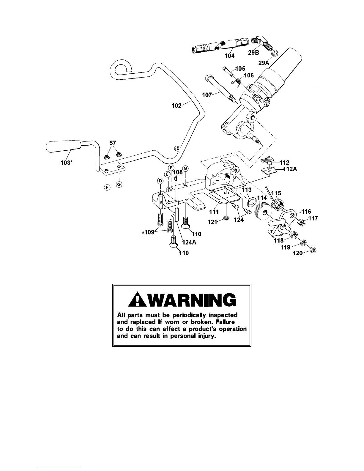
102 Handle Assembly 1 016931
103 Knob 1 008852
104 Hose Assembly 1 306376
105 Motor Latch Pin 1 020642
106 Motor Latch Spring 1 020645
107 Support Shaft 1 008539
108 Strap Guide Spring 1 023353
109 SHCS, 1/4-20 x 3/4 2 009041
110 FHSCS, 5/16-18 x 3/4 2 008153
111 Tensioner Frame 1 422777
112 Gripper plug 1 422939
112A Guide 1 422942
113 Spring Washer 1 006566
114 Feedwheel 1 422786
115 Motor Spring 1 422785
116 Side Plate 1 423295
117 Flexloc Nut, 3/8-24 2 003868
118 Bushing 1 006567
119 Washer 1 005208
120 Hex Nut (L.H.) 5/16-24 x 1/4 1 005209
121 Truarc #5100-34 1 423294
122 Thrust Washer 1 024729
123 Sealer Guard 1 422131
124 Wear plug (1/2) 2 261854
124A Rear guide pad (1/2) 1 263383
125 Warning Sign 1 267596
129 SHCS, #8-32 x 1/4 1 014546
131 Nameplate 1 433386
132 Information Sign 2 024727
133 Safety Sign 1 286373
!!!! When ordering parts show tool model, part number and name.
!!!! Common hardware parts may be obtained from local hardware suppliers.
!!!! All recommended spare parts are underlined and should be stocked.
13
Page 14
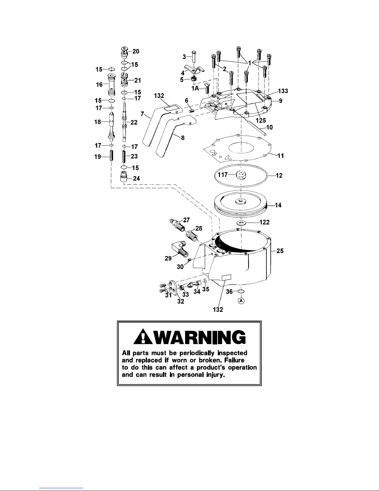
* Apply one drop of Loctite #242 Sealant to cleaned parts. Allow 12 hours to set if possible.
*** Use Loctite #609.
14
Page 15
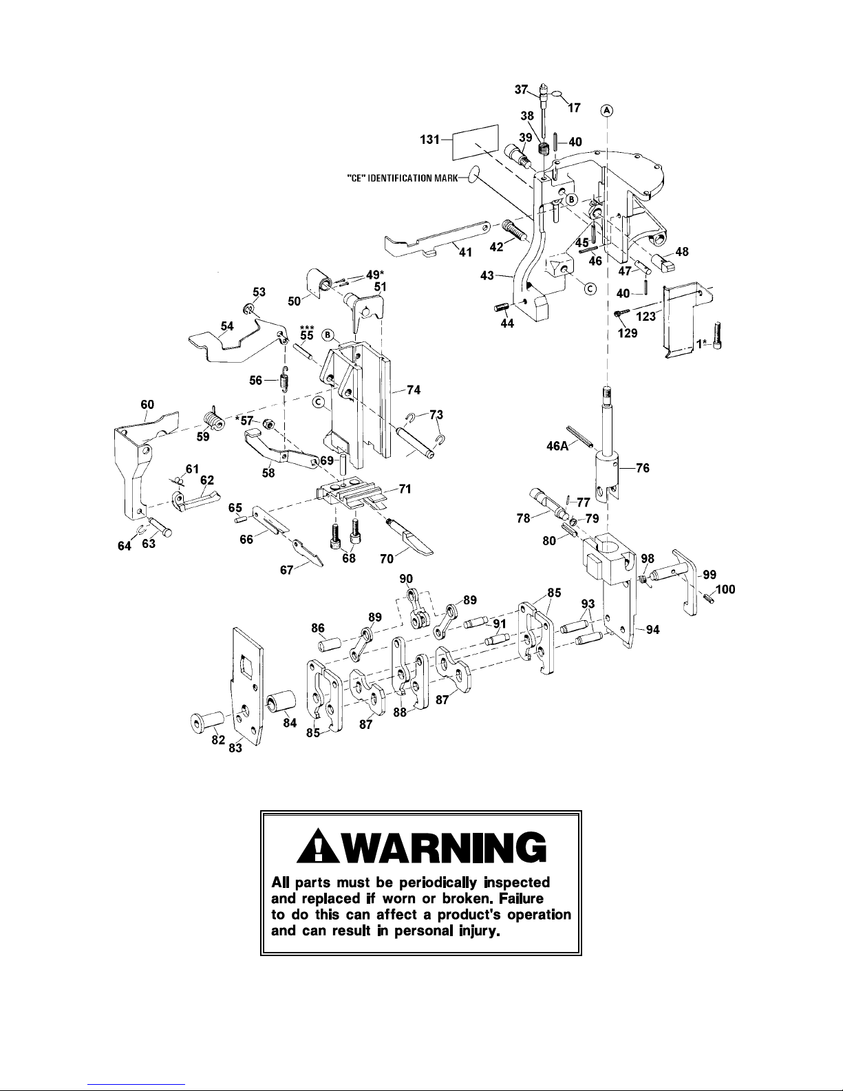
15
Page 16
* Apply one drop of Loctite #242 Sealant to cleaned parts. Allow 12 hours to set if possible.
16
Page 17
TOOL HOUSING, DISASSEMBLY & REASSEMBLY
The following instructions cover the removal and replacement of the following tool components:
!!!! Seal Magazine and Sealer Mechanism
!!!! Seal Ejector and Ejector Lever
!!!! Feedwheel
!!!! Gripper Plug
Refer to the exploded views and parts list in this manual for addition information and details.
The following tools are required for perform these operations: 3 Allen wrenches 1/8", 3/16", and
1/4", Truarc pliers, 1/2", 9/16" 3/8" and 1/4" socket wrenches, a rubber mallet, common pliers,
screwdriver and a set of assorted punches.
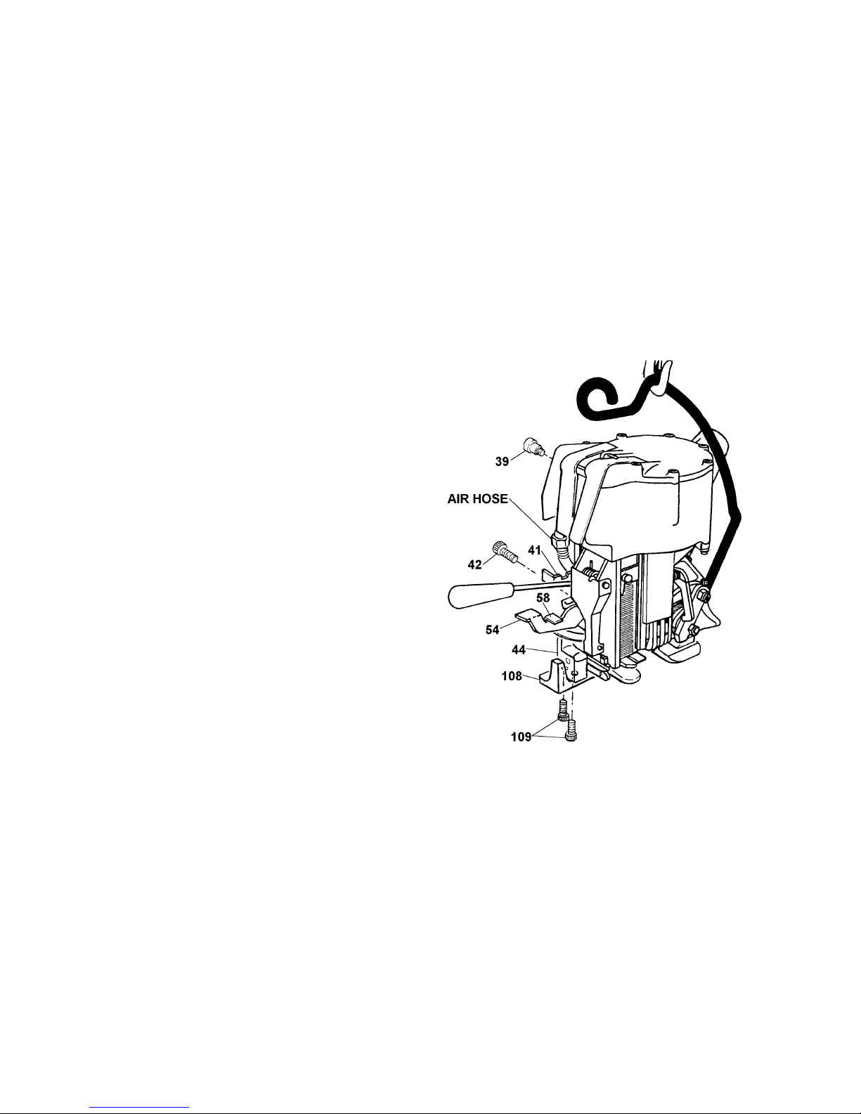
SEAL MAGAZINE AND SEALER MECHANISM - DISASSEMBLY:
Disconnect the air supply from tool and remove
the seals from the magazine and sealer
mechanism. Release the gripper lever (58) by
pressing the gripper trigger (54). Press motor
latch (41) to drop feedwheel. Loosen cutter
adjustment set screw (44). Remove the two
magazine screws (39 & 42) on the side of the
sealer frame.
Remove the two socket head cap screws (109)
from the bottom of the base. With the tool lying
on its left side, swing the rear of the base down
and away from the sealer frame. Tilt the top of
the magazine away from the sealer mechanism
and lift the magazine assembly out.
The magazine and sealer mechanisms are now
accessible for examination and replacement of
worn or broken parts. The sealer mechanism is
serviced by removing the cutter blade. Clean the
parts. Jaws and crimpers are replaced as
required. After the necessary repairs have been
made grease the parts or apply light machine oil.
The tool is now ready for assembly.
SEAL MAGAZINE AND SEALER MECHANISM - ASSEMBLY:
With the sealer mechanism fully assembled and in place, insert the magazine by placing the lower
portion of the magazine between the sealer mechanism and frame. Tilt the top forward to align
properly with the sealer mechanism.
Swing the base up against the sealer frame. Be sure the strap guide spring (108) is in its proper
position in the base. Insert and tighten the two socket head cap screws (109) through the base.
Insert the top and bottom shoulder screw (39 & 42) through the sealer frame and into the
magazine. Snug - do not tighten.
17
Page 18
TOOL HOUSING, DISASSEMBLY & REASSEMBLY, Continued
Connect air supply and hold in sealer lever (8). With jaws in fully downward position, adjust the
cutter adjustment screw (44). Tighten both magazine screws (39 & 42) through the sealer frame.
Insert seals into the magazine and operate the sealer mechanism at it's recommended air pressure
through 3 or 4 cycles to check tightness of the cutter adjustment screw and see that seals feed
properly. If the sealer mechanism is excessively tight, back off the cutter adjustment set screw
slightly.
Apply a strap under tension to be sure that all elements of tool operate properly.
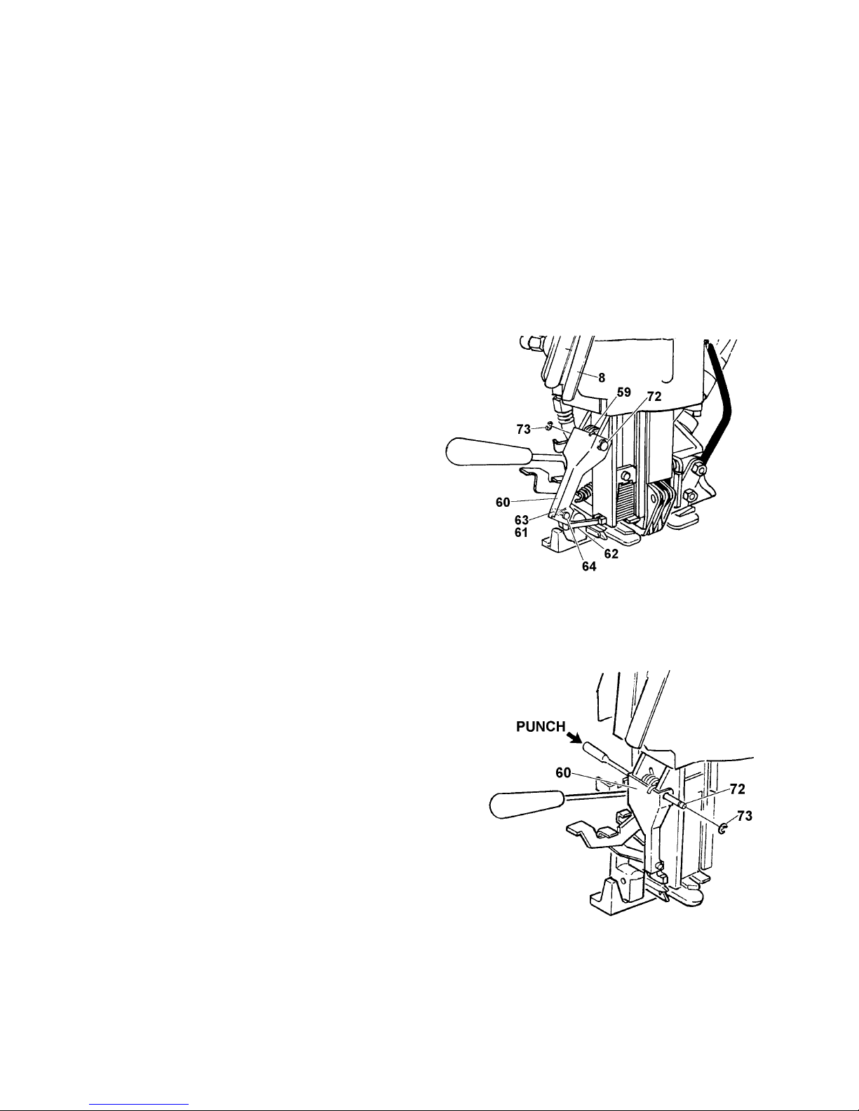
SEAL EJECTOR & EJECTOR LEVER - DISASSEMBLY
Remove the seals from the magazine. Remove
the Truarc (73) from the left side of the ejector
arm pin (72) then drive out ejector arm pin (72)
from the left side of tool. Remove ejector arm
spring (59). Hold gripper lever (58) down, pull
out ejector lever (60).
Drive out roll pin (63) from ejector pin (64). Be
sure to support ejector lever. Remove pin (64),
ejector (62) and spring (61). Replace the ejector
lever and/or the ejector as necessary. Reassemble with new ejector following these steps
in reverse order.
NOTE:If the ejector only needs to be replaced, it
can be removed without removing the ejector lever
following the 3 steps above.
SEAL EJECTOR & EJECTOR LEVER - ASSEMBLY
Insert ejector (62) into cutter block (71) slot, hold gripper
lever (58) down and slide ejector lever (60) into position.
Insert ejector arm spring (59) ahead of the top of the
ejector arm so it will slide under the edge of the cylinder.
Start ejector arm pin (72) through right side of ejector
lever and magazine.
Insert a punch from the left side to hold the spring in
alignment. Tap ejector arm pin (72) in from the right side,
while removing the aligning punch at the same time.
Push on lower part of ejector lever (60) to align holes on
left side of tool. Finish tapping in ejector arm pin (72).
Replace Truarc (73). Insert seals in the magazine.
Operate the sealer mechanism through 3 or 4 cycles to
check and see that seals feed properly. Apply a strap
under
tension to be sure that all elements of tool operate properly.
18
Page 19
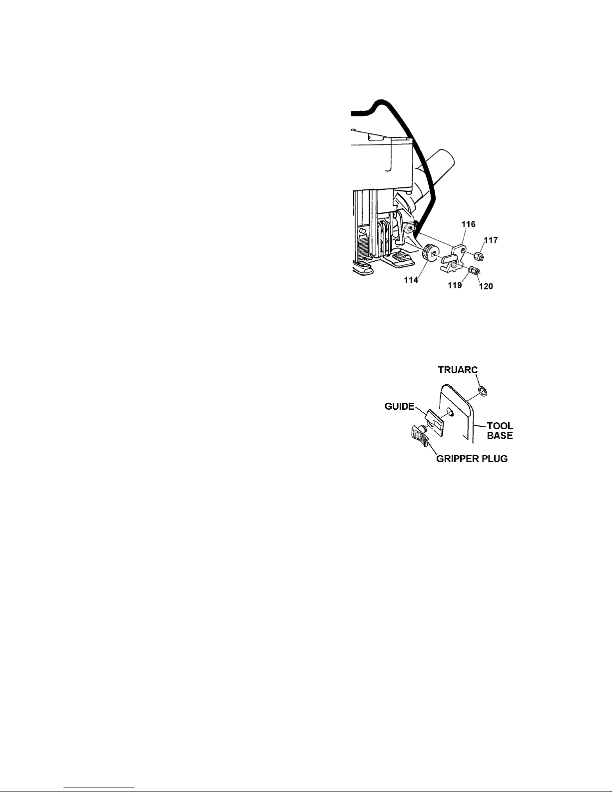
FEEDWHEEL
Remove the left hand nut (120) from the feedwheel shaft
and lock nut (117) from the support shaft. With motor
and gear housing latched in up position, remove washer
(119), side plate (116) and feedwheel (114). Replace the
feedwheel onto the feedwheel shaft. Apply grease to the
bore of the side plate's bushing and reassemble the
remaining parts in reverse order.
GRIPPER & GUIDE
Turn the tool on it's side. Motor and gear housing should be
latched in up position. With a Truarc pliers remove the Truarc
from the gripper plug stem. Push the gripper plug and guide up
and out. Insert a new gripper plug or guide and install the
Truarc.
19
Page 20

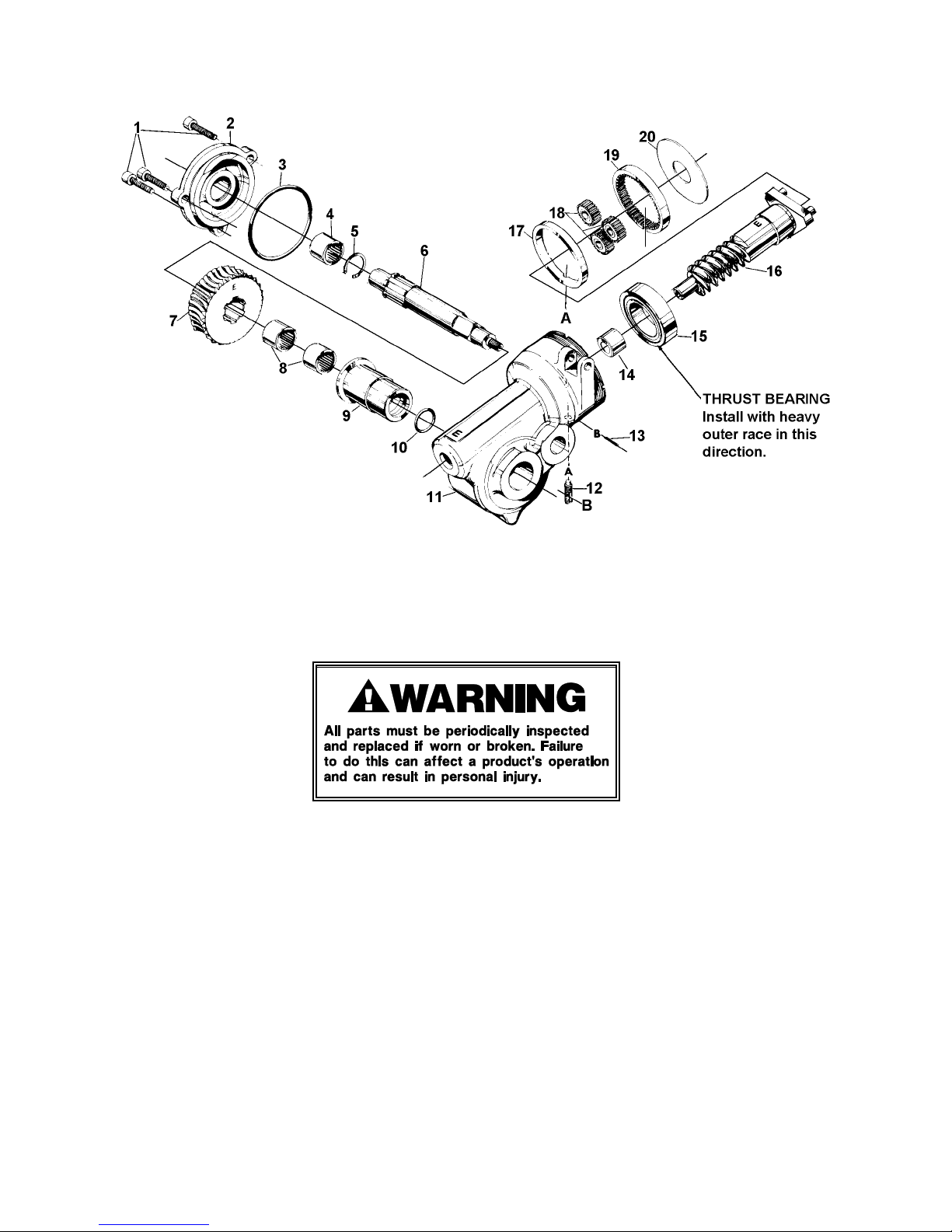
PARTS LISTS & EXPLODED VIEW
GEAR HOUSING
KEY DESCRIPTION QTY. PART NO.
1 SHCS, 1/4-20 x 3/4 3 009041
2 Gear Housing Cover 1 020623
3 O-Ring 1 008546
4 Needle Bearing 1 008549
5 Truarc #5008-75 1 008547
6 Feedwheel Shaft 1 006585
7 Worm Wheel 1 023561
8 Wheel Bearing 2 006563
9 Gear Housing Bushing 1 006581
10 O-Ring 1 006594
11 Gear Housing 1 023564
12 Lock Screw 1 008581
13 Roll Pin 5/64 x 7/16 1 008582
or Cotter pin, 1/16 x 5/8 1 181482
14 Needle Bearing 1 008751
15 Thrust Bearing 1 023754
16 Worm Assembly 1 023563
17 Spacer Ring 1 008534
18 Idler Gear Assembly 3 008815
19 Ring Gear 1 008524
20 Washer 1 008536
!!!! When ordering parts show tool model, part number and name.
!!!! Common hardware parts may be obtained from local hardware suppliers.
!!!! All recommended spare parts are underlined and should be stocked.
GEAR HOUSING DISASSEMBLY & REASSEMBLY
1. Remove the washer (20) the ring gear (19) and the idler gear assembly (18).
2. Remove the roll pin (13) and loosen the lock screw (12) to permit removal of the spacer ring
(17).
3. Remove the worm assembly (16). Note that the thrust bearing (15) must be reinstalled with the
heavy side of the outer race positioned as shown.
4. Remove the three gear housing cover mounting screws (1), then remove the housing cover (2).
Withdraw the feedwheel shaft (6) and the worm wheel (7). Note that the worm wheel (7) must
be reinstalled with the letter "E" positioned as shown.
5. Parts and housing must be free of metallic particles. Clean as required and regrease using
non-fluid oil K-55. Reassembly gear housing by reversing above instructions. Fill gear housing
to approximately 1/2 full.
6. When reassembled, check gearing for freeness by turning worm assembly (16) clockwise
before attaching air motor.
20
Page 21
21
Page 22

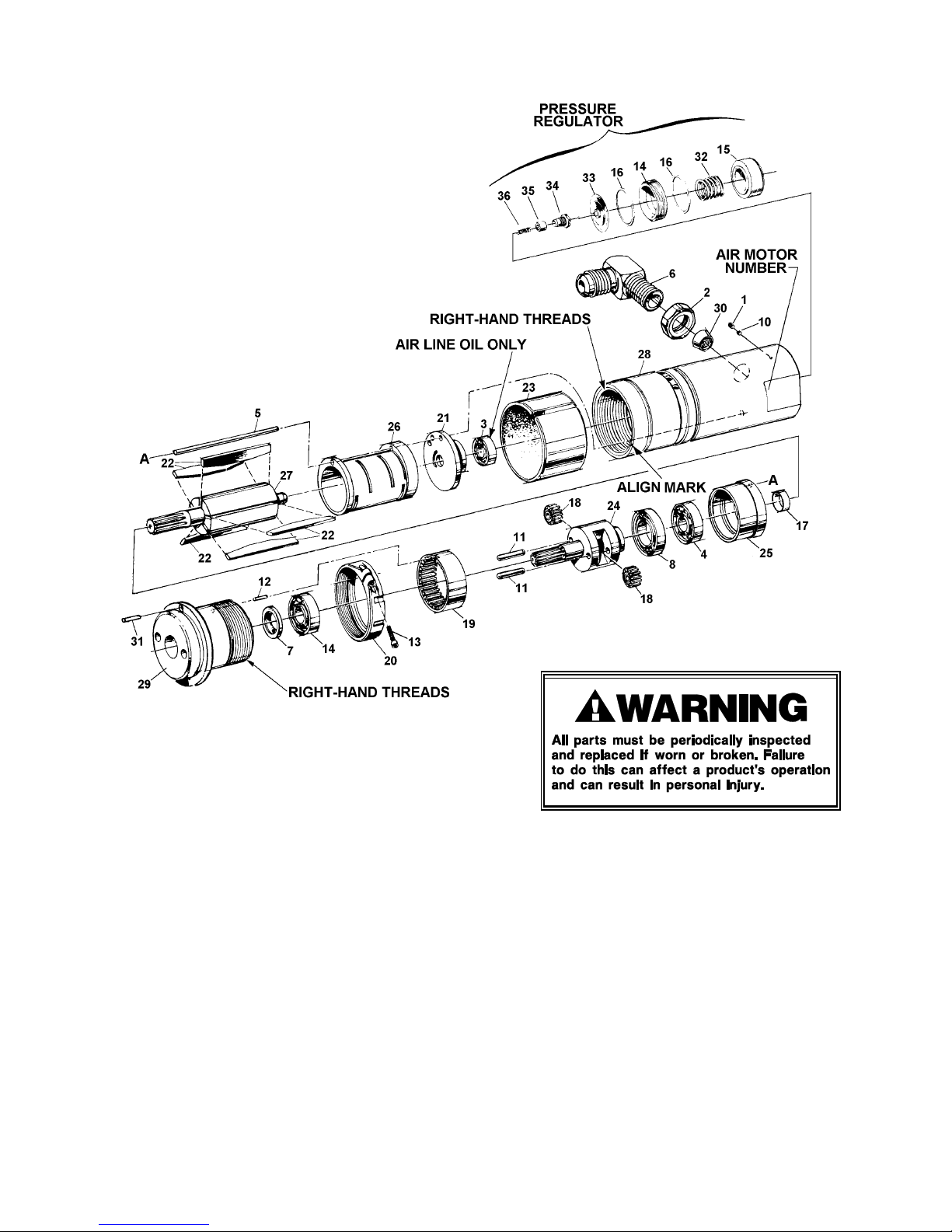
PARTS LISTS & EXPLODED VIEW
AIR MOTOR 18R36, Part No. 422912
KEY QTY. PART NO. DESCRIPTION
1 1 020173 Set Screw, flat point, #10-24 x 3/16
2 1 023087 1/4-18 NPT, Tru-Seal, Miller
3 1 024633 Ball Bearing, Fafnir #AS1K7-R1#2
4 1 023481 Ball Bearing, General #R-06-00-04
5 1 023510 Align pin
6 1 023524 90° Elbow, 1/4 tube, x 1/4-18 NPS
7 1 023558 Seal, Trostel #B-44-28-2
8 1 023552 Aircraft ball bearing, fafnir #B-538
9 1 306396 Ball bearing, MRC #1901S
10 1 023540 Lock plug
11 2 023555 Pin, 5/32 x 5/8, Torr. #Q-8254, spherical ends
12 1 023536 Pin, 1/16 x 1/4, Groove Pin #GP1-062X250-70
13 1 008731 SHCS, #10-24 x 3/4
14 1 023511 Diaphragm nut
15 1 023512 Pressure adjusting screw
16 2 023543 Slip ring
17 1 024602 Spacer
18 2 024607 Idler assembly
19 1 024608 Ring gear
20 1 023534 Ring nut
21 1 024643 Back end plate
22 5 024612 Vane
23 1 024618 Deflector assembly
24 1 422783 Cage
25 1 024622 Front end plate
26 1 024623 Cylinder
27 1 024625 Rotor
28 1 422782 Motor housing
29 1 422781 Gear housing
30 1 024630 Filter
31 1 023533 Pin, 7/64 x 1/4, Driv-Lok Type A-3
32 1 020166 Regulator spring
33 1 023570 Pressure regulator diaphragm assembly
34 1 023537 Valve seat
35 1 023572 Pressure regulator valve
36 1 023536 Valve spring
!!!! When ordering parts show tool model, part number and name.
!!!! Common hardware parts may be obtained from local hardware suppliers.
!!!! All recommended spare parts are underlined and should be stocked.
22
Page 23
NOTES:
Idler assemblies (Key 18) and Vanes (Key 22) must soak in air line oil overnight before assembly.
All motor parts are to be lubricated with Air Line Oil (Signode Part No. 008556, Non-Fluid Oil Co.,
Grade #LS-1236.
Idler assemblies and bearings except Key 3 are to be lubricated with non-fluid oil #K55 (Non-Fluid
Oil Co.) or equivalent.
SEE NEXT PAGE FOR DISASSEMBLY & REASSEMBLY INSTRUCTIONS . . .
23
Page 24

AIR MOTOR 18R36, DISASSEMBLY & REASSEMBLY
Considerable care must be used when an air motor is disassembled. Lack of lubrication and dirty
unfiltered air are the main causes of malfunctions, which are corrected by proper maintenance of
the filter, regulator and lubricator unit. Review Pneumatic Information in this manual for
installation and maintenance recommendations.
REGULATOR DISASSEMBLY:
1. Remove the motor pressure regulator parts, clean and replace if necessary.
2. Reassemble and test tool before proceeding with the Motor Disassembly.
MOTOR DISASSEMBLY:
1. Loosen cap screw (13). Loosen ring nut (20) and remove motor from tool gear housing.
2. Hold motor housing (28) lightly in a vise, and remove gear housing (29) by rotating counter-
clockwise when facing gearing end.
3. Keep groups of parts together without separating bearings unless their replacement is
necessary.
4. Wash out any dirty parts using a fresh clean oil base type solvent.
5. Rotate bearings to make certain parts are clean. Apply a light coating of grease, #K-55, non-
fluid oil, or an equivalent light cup grease. Do not apply grease on rotor (27) since this will
cause sticking of vanes (22). Do not grease bearing (3) located in back end plate (21).
Lubricate rotor, vanes and end bearing with air line oil only.
6. Replace gearing (18, 24, 27) and vanes (22) if worn or cracked. Apply a light coating of grease
to gearing and air line oil to rotor and vanes.
REASSEMBLY:
1. Begin reassembly by making certain that the alignment pin (5) is correctly positioned to align
the back-end plate (21), the cylinder (26) and the front-end plate (25) with the hole in the motor
housing (28).
2. Assemble parts (8, 11, 12, 14, 18, 19, 24) and place them in the gear housing (29). Make certain
that the roll pin (12) enters into the slot of the ring gear (19).
3. Assemble the gear housing (29) and the ring nut (20) to the motor housing (28). Hand tighten.
Rotate the pinion of the gear case (24) by hand in the clockwise direction to be certain all parts
are free. If parts are not free, gears are not properly meshed.
4. Add one teaspoon or squirt air line lubricating oil into the motor. Connect the air hose with
the pressure set at approximately 20 p.s.i.g. With motor housing in vise, slowly tighten gear
housing in a clockwise direction while the motor is rotating. Tighten the motor, noting an
increase in speed. The correct adjustment is about 400-600 inch lbs. If the motor is over
tightened it will slow down. When set, attach the air motor to the gear housing.
24
Page 25
TROUBLESHOOTING
The following items are the most common types of tool malfunctions. For symptoms or remedies
not shown, contact your Signode service representative for additional information and details. The
following tool conditions are shown in this manual:
TENSIONING
#1 - Motor will not start when tensioning lever is pressed.
#2 - Air motor runs slowly or sluggishly.
#3 - Air motor runs slowly or sluggishly.
#4 - Feedwheel slips on top strap during tensioning.
#5 - Bottom strap slips out of tool during tensioning.
#6 - Feedwheel will not drop onto strap when tensioning lever is pressed.
#7 - Feedwheel will not lift off strap after cycle is completed.
#8 - Motor runs slowly as soon as air is connected to tool.
#9 - Tool breaks strap during tool removal or tensioning.
SEALING
#10 - Joints failing after tool removal.
#11 - Sealing mechanism crushes or deforms seals.
#12 - Tool won't complete sealing cycle unless sealing lever is held down manually.
#13 - Sealing mechanism stalls in down position.
STRAP CUT-OFF
#14 - Tool will not cut off strap after sealing.
SEAL EJECTION
#15 - Seals do not eject fully and/or cutter blade cuts off seal ends.
#16 - Ejector does not pick up seals.
#1 CONDITION: Motor will not start when tensioning lever is pressed.
CAUSE REMEDY
1. No air reaching tool.
2. Air motor filter screen is blocked with
rust or dirt.
3. Air motor is dry. Oil has evaporated
leaving sticky varnish which prevents
motor vanes from extending.
1. Check gauge on filter-regulatorlubricator (FRL) for proper 65-90 psig
pressure setting. Check air line from
FRL to tool for blockage.
2. Check air motor filter screen for
obstruction then clean or replace as
required.
3. Add teaspoon air line oil directly into
motor at elbow. Reconnect air line and
test. Tap motor lightly w/rubber mallet
to free vanes. Check function of
lubricator.
25
Page 26

TROUBLESHOOTING, Continued
#2 CONDITION: Air motor runs slowly or sluggishly.
CAUSE REMEDY
1. Air supply to tool is restricted.
1A. Check gauge on FRL for proper 65-90
psig pressure setting.
1B. Check air line from FRL for blockage
1C. Check for satisfactory air volume
reaching tool by either of the following
methods:
a. Install an in-line air gauge at the tool if
one is available. Hook up air and record
pressure reading. With no strap in tool,
press tension lever and record gauge
reading. If pressure drops more than 15
psig, air supply is inadequate. Remedy
is to improve air flow by shortening
length of line from FRL to tool,
increasing size of air lines, or checking
for obstructions to or from FRL unit.
Example: If piping system equipped
with shutoff valves, ensure valve are
fully open.
b. If no in-line gauge available, repeat step
"a", above, except use gauge on FRL
unit.
2. Air motor filter screen is blocked with
rust or dirt.
3. Air motor is dry, unlubricated, causing
motor to run slowly.
2. Check air motor filter screen for
obstruction then clean or replace as
required.
3. Add teaspoon air line oil directly into
the motor at elbow. Place rag around
motor, reconnect air and test. If motor
speed increases, motor was dry. Check
lubricator for proper adjustment,
quantity and type of oil.
26
Page 27
#3 CONDITION: Air motor runs slowly or sluggishly.
CAUSE REMEDY
1. Valve latch (Page 11, Key 4) has popped
up.
1. Check by pressing tension lever fully
and then releasing lever. Press tension
lever and hold lever fully in. If motor
speed increases, valve latch is popped
up, correct by first loosening lock
screw (Page 11, Key 30). Push valve
latch pin down and hold while
tightening lock screw.
2. Insufficiently lubricated strap.
2. Use lubricated strapping.
#4 CONDITION: Feedwheel slips on top strap during tensioning.
CAUSE REMEDY
1. Feedwheel teeth packed with dirt or grit.
2. Feedwheel teeth worn or chipped.
3. Bushing in outer link worn.
1. Clean feedwheel teeth with wire brush.
2. Replace feedwheel (Page 13, Key 114).
3. Check I.D. of bushing to determine if
hole is elongated. Replace if visually
elongated.
4. Strap not aligned properly - outer link
4. Align strap in tool properly.
coming down on strap.
5. Motor assembly not dropping the
feedwheel on to the strap.
5. Lubricate the support shaft (Page 13,
Key 107).
#5 CONDITION: Bottom strap slips out of tool during tensioning.
CAUSE REMEDY
1. Gripper plug teeth packed with dirt or
grit.
2. Gripper plug teeth worn or chipped.
1. Clean teeth feedwheel with wire brush
(Page 13, Key 114).
2. Replace gripper plug.
#6 CONDITION: Feedwheel will not drop onto strap when tensioning lever is pressed.
CAUSE REMEDY
1. Motor plunger (Page 11, Key 37)
binding.
1. Invert tool. Add a few drops of air line
oil to the hole in sealer frame for the
motor plunger.
27
Page 28
TROUBLESHOOTING, Continued
#7 CONDITION: Feedwheel will not lift off strap after cycle is completed.
CAUSE REMEDY
1. Motor pickup latch (Page 11, Key 99) is
worn.
2. Motor is dry, preventing motor from
backing up and causing feedwheel teeth
to remain imbedded in strap.
#8 CONDITION: Motor runs slowly as soon as air is connected to tool.
CAUSE REMEDY
1. Check wing of motor pickup latch that
contacts outer link, for wear. Replace if
severely worn.
2. Add teaspoon of air line oil directly into
motor at elbow. Reconnect air line and
test as follows:
a. Load tool with strap.
b. Press tension lever and allow to
tension until motor stalls.
c. Press valve latch (Page 11, Key 4). Tool
must release tension by feedwheel
rolling back. If tool does not release
tension, problem exists in motor or
gear housing gearing.
1. Lower O-ring on tensioner valve stem
(Page 11, Key 18) is ripped or has blown
off.
#9 CONDITION: Tool breaks strap at feedwheel, gripper, corner of load, or at joint during tool
removal or tensioning.
CAUSE REMEDY
1. Excessively applied tension.
2. Strap in use is insufficiently lubricated.
3. Strap not aligned properly - outer link
coming down on strap.
1. Replace lower tensioner valve O-ring
(Page 11, Key 17).
1A. Reduce air pressure.
1B. Adjust motor to produce less tension
by loosening lock screw on motor, and
then turning adjusting screw out,
counterclockwise. Tighten lock screw
after making adjustment.
2. Use lubricated strap.
3. Align straps in tool properly.
28
Page 29
#10 CONDITION: Joints failing after tool removal.
CAUSE REMEDY
1. Low joint strength caused by worn
sealer mechanism parts.
1. Examine sealer mechanism for worn
jaws, crimpers and pins. Replace all
sealer mechainsm parts.
2. Application related; i.e., strap not strong
enough to contain load; load subjected
to impact; load expands after strapping.
2. Review application to determine that
strap-seal-tool in use is adequate for
application.
3. Strap tension set too high.
3. Readjust tension to a lower setting per
adjustment instructions.
#11 CONDITION: Sealing mechanism crushes or deforms seals.
CAUSE REMEDY
1. Worn ram and/or ram release pin. 1. Disassemble tool. Examine ram (76)
and ram release pin (79). Replace as
required.
#12 CONDITION: Tool won't complete sealing cycle unless sealing lever is held down manually.
CAUSE REMEDY
1. Broken sure seal pawl spring (Page 11,
Key 33).
2. Worn sure seal pawl (Page 11, Key 34).
3. Worn sealer valve stem (Page 11, Key
22).
1. Replace sure seal pawl spring.
2. Replace sure seal pawl.
3. Replace sealer valve stem.
29
Page 30
TROUBLESHOOTING, Continued
#13 CONDITION: Sealing mechanism stalls in down position.
CAUSE REMEDY
1. Insufficient air pressure to complete
sealing.
2. Broken sealer mechanism part.
#14 CONDITION: Tool will not cut off strap after sealing.
CAUSE REMEDY
1. Cutter blade out of adjustment.
2. Cutter blade worn.
1. Increase air pressure until sealing is
completed.
WARNING - Air pressure must be maintained
in the 65-90 psig range.
2. Carefully inspect sealer mechanism for
broken parts. Jaw stack can be
returned to the up position by inserting
screw driver in slot in sure seal pawl
and rotating clockwise.
WARNING - Stand to side of and hold tool
securely when rotating pawl on jammed tool.
1. Adjust cutter.
2. Replace cutter blade.
3. Cutting leg on cutter block worn or
broken.
3. Replace cutter block.
30
Page 31

#15 CONDITION: Seals do not eject fully and/or cutter blade cuts off seal ends.
CAUSE REMEDY
1. Broken ejector spring (Page 12, Key 61).
2. Severely worn tip on ejector (Page 12,
Key 62).
3. Severely worn cutter blade (Page 12,
Key 83).
4. Bent or cracked ejector lever (Page 12,
Key 60).
5. Screws (Page 12, Key 68) securing
cutter block to magazine are loose.
6. Seal jam.
1. Replace ejector spring.
2. Replace ejector.
3. Replace cutter blade.
4. Check by first examining ejector lever
for cracks. If no cracks are found,
connect air to tool and note position of
lugs on ejector in relation to cutter
block. Front of lugs must contact rear
of cutter block. If lugs do not contact
cutter block, ejector lever is bent and
must be replaced.
5. Disassemble tool, remove screws. Add
one drop of Loctite #242 to each screw.
Reassemble.
6. Disconnect air source. Pull back ejector
lever and secure in retracted position
by placing an object such as a
screwdriver between the magazine and
the ejector lever. Lightly tap the seal
back into the magazine. Remove the
seal from the magazine and discard
with any plastic beading possibly
lodged in the cutter block area.
31
Page 32

TROUBLESHOOTING, Continued
#16 CONDITION: Ejector does not pick up seals.
CAUSE REMEDY
1. Seals improperly seated in cutter block
track.
2. Dirt in cutter block rear track.
3. Broken ejector tip.
4. Screws securing cutter block to
magazine are loose.
5. Ram roll pin bent.
6. Broken or bent ejector lever (60) wing
behind jaw stack.
7. Ejector lever.
1. Position seals properly.
2. Brush dirt out of cutter block rear track.
3. Replace ejector.
4. Disassemble tool and tighten screws.
5. Install new roll pin (Page 12, Key 46).
6. Replace ejector lever.
7. Lightly tap the seal back into the
magazine. Discard the seal and any
plastic filament lodged in the cutter
block area.
32
Page 33

TOOL MAINTENANCE
The most common reason for poor tool performance and incorrectly formed straps joints is
improper tool maintenance. The easiest way to determine if a tool is performing correctly is by
inspecting the strap joint. Having a tool maintenance program is a simple task which consists of
three parts. First, a quick daily inspection of the tool for any worn or broken parts. Secondly, keep
each tool on a schedule of service intervals for cleaning and lubrication. Third, when problems do
occur, use the troubleshooting guide to properly determine and fix problems before they lead to
more serious tool conditions. Each of these three tasks have been outlined for this particular tool,
read and understand all information for improving the life and performance of the tool.
TOOL INSPECTION
Visually inspect the exterior of the tool on a daily basis. Decreased tool life can be prevented by
early detection of broken parts. Replace all broken parts with new parts. Review the Parts
Removal, Replacement & Adjustments portion of this manual for information and details.
SERVICE INTERVALS
This tool, like most Signode tools, can be used with various sizes of strap which cause different
rates of component wear. Also, wear is affected by the environment and tension that the tool
applies. In the worst case, heavy gauge wide strapping. All critical moving components of the tool
should be inspected at particular intervals, some more often than others. Broken parts can
decrease sealing effort, leading to additional component wear and produce lower joint strength.
Inspect the components of the sealing mechanism when:
A. Joint does not appear as shown in this manual or visually it is detected that the joint is not
all formed or formed improperly.
B. Sealing effort requires higher air pressure or tool is difficult to remove from strap.
C. When scheduled.
If there is any question that joint formation is not as shown or is
suspect, it is important that you contact your tool representative immediately.
The feed wheel and the gripper teeth are also subject to wear and chipping. A daily cleaning of
these parts by brushing off debris will be important to maintaining long life. The first indication of
wear will be strap slippage during tensioning. The operator of the tool should be instructed on
how to determine when the strap slips during tensioning. Sometimes the teeth need to be cleaned
with a wire brush, but if slipping is allowed to continue, the parts will need to be replaced. Using
the tool in a dirty environment will increase feedwheel and gripper plug wear.
NOTE: On some Signode tools the feedwheel can be cleaned by holding the tool open in the strap
loading position while the tool runs without strap and using a wire brush to clean the feedwheel
as it rotates.
Inspect the components of the tensioner mechanism when:
A. Strap slips when being tensioning.
B. Evidence of feedwheel milling on the strap face.
C. When scheduled.
33
Page 34

TOOL MAINTENANCE, Continued
TOOL LUBRICATION
Signode tools use a variety of greases and oils, all of which can be ordered through Signode
using the appropriate description shown below.
!!!! Air Line Oil, Part No. 008556
!!!! K55 Grease, Part No. 177029
THREAD SEALANTS
Signode tools use a variety of thread sealants, all of which can be ordered in 10 ml bottles through
Signode using the appropriate description shown below.
!!!! Loctite #222, Part No. 422794
!!!! Loctite #242, Part No. 422795
!!!! Loctite #609, Part No. 422797
34
Page 35
EU Declaration of Conformity
The Supply of Machinery (safety) Regulations
1992 (S.I. 1992/3073)
It is hereby declared that the undermentioned machinery has been designed and
constructed to comply with the health and safety requirements defined in EC Directive
89/392/EEC
Machine Supplier: Signode, Division of ITW Ltd.
Queensway, Fforestfach
Swansea SA5 4ED
Machine Description: AMPT
Machine Type: Pneumatic Combination Hand Strapping tool.
Provisions with which machine complies:
89/392/EEC, 91/368/EEC
Harmonized EuroNorms with which machine complies:
EN 292:1, EN 292:2, EN 294, EN 349
Technical Standards with which machine complies:
NA
Signature: Date: 1 SEPT 2000
(Peter Oseland)
35
Page 36

SIGNODE
NEW TOOL WARRANTY
Signode Engineered Products Warrants that a new Signode strapping tool will operate per functional
specifications for a period of sixty (60) days after the date of shipment to the owner's place of business.
Normal wearing parts, as outlined in the Operation, Parts & Safety manual, are covered by a thirty (30) day
warranty unless, in Signode's judgement, these parts have been subjected to abnormal or extreme usage.
Signode's sole liability hereunder will be to repair or replace, without charge, F.O.B. Signode's Glenview,
Illinois plant, any tool which proves to not operate per functional specifications within the stated period.
Signode reserves the right to replace any tool which proves not to operate per functional specifications
with a new or like-new tool of the same model if in Signode's judgement such replacement is appropriate.
Any new replacement tool provided to an owner will carry a full sixty (60) day warranty. Any warranty
repaired tool or like-new replacement tool will carry a warranty for the balance of the time remaining on the
initial sixty (60) day warranty. This warranty will be extended to compensate for the time the tool is in
Signode's possession for warranty repairs.
This warranty is void as to any tool which has been: (I) subjected to mis-use, misapplication, accident,
damage, or repaired with other than genuine Signode replacement parts, (II) improperly maintained, or
adjusted, or damaged in transit or handling; (III) used with improperly filtered, unlubricated air or improper
strapping material, (IV) in Signode's opinion, altered or repaired in a way that affects or detracts from the
performance of the tool.
SIGNODE MAKES NO WARRANTY, EXPRESSED OR IMPLIED, RELATING TO MERCHANTABILITY,
FITNESS OR OTHERWISE EXCEPT AS STATED ABOVE AND SIGNODE'S LIABILITY AS ASSUMED ABOVE
IS IN LIEU OF ALL OTHERS ARISING OUT OF OR IN CONNECTION WITH THE USE AND PERFORMANCE
OF THE TOOL. IT IS EXPRESSLY UNDERSTOOD THAT SIGNODE SHALL IN NO EVENT BE LIABLE FOR
ANY INDIRECT OR CONSEQUENTIAL DAMAGES INCLUDING, BUT NOT LIMITED TO, DAMAGES WHICH
MAY ARISE FROM LOSS OF ANTICIPATED PROFITS OR PRODUCTION, SPOILAGE OF MATERIALS,
INCREASED COSTS OF OPERATION OR OTHERWISE.
Considerable effort has be made to ensure that this product conforms to our high quality standards.
However, should you experience any difficulties, please contact your Sales Representative providing
samples and the manufacturing code specified on the tool.
Thank you for your help.
SIGNODE ENGINEERED PRODUCTS
Hand Tool Division
3620 W. Lake Avenue, Glenview, Illinois 60025
© Copyright 2000, Signode 437118 9/2000
 Loading...