

Signode AMPT-12 Operation, Parts And Safe

AMPT-12
POWERED COMBINATION STRAPPING TOOL
SIGNODE !
! 3620 WEST LAKE AVENUE !!!! GLENVIEW, ILLINOIS 60025
!!
READ THESE INSTRUCTIONS CAREFULLY.
FAILURE TO FOLLOW THESE INSTRUCTIONS CAN RESULT IN SEVERE PERSONAL INJURY.
GENERAL SAFETY CONSIDERATIONS
1. STRAP BREAKAGE HAZARD.
Improper operation of the tool or sharp corners on the load can result in strap
breakage during tensioning, which could result in the following:
!!!! A sudden loss of balance causing you to fall.
!!!! Both tool and strap flying violently towards your face.
Failure to place the strap properly around the load or an unstable or shifted load could result
in a sudden loss of strap tension during tensioning. This could result in a sudden loss of
balance causing you to fall.
Read the tool's operating instructions. If the load corners are sharp use edge protectors.
Place the strap correctly around a properly positioned load.
!!!! Positioning yourself in-line with the strap, during tensioning and sealing, can result in
severe personal injury from flying strap or tool. When tensioning or sealing, position
yourself to one side of the strap and keep all bystanders away.
!!!! Using strap not recommended for this tool can result in strap breakage during tensioning.
Use the correct Signode products for your application.
2. TRAINING.
This tool must not be used by persons not properly trained in its use. Be certain that you
receive proper training from your employer. If you have any questions contact your Signode
Representative.
3. EYE INJURY HAZARD.
Failure to wear safety glasses with side shields can result in severe eye injury or
blindness. Always wear safety glasses with side shields which conform to ANSI
Standard Z87.1 or EN 166.
4. FALL HAZARD.
Maintaining improper footing and/or balance when operating the tool can cause you to fall. Do
not use the tool when you are in an awkward position.
5. CUT HAZARD.
Handling strap or sharp parts could result in cut hands or fingers. Wear protective
gloves.
2
6. TOOL CARE.
Take good care of the tool. Inspect and clean it daily, lubricate it weekly and adjust when
necessary. Replace any worn or broken parts.
7. WORK AREA.
Keep work areas uncluttered and well lighted.
Several types of strap can be used with this tool. Use the correct Signode products for your
application. If you need help contact your Signode Representative.
SAFETY PROCEDURES FOR TOOL OPERATION
1. Before using this tool, read its Operation and Safety instructions.
!!!! Do not exceed the operating air pressures stated elsewhere in the manual.
!!!! Use Signode's approved filter-regulator-lubricator unit (P-173111).
!!!! Never operate a pneumatic tool with a bottled air or gas source.
!!!! For tension adjustments, follow instructions in this manual. For all other adjustments,
repairs or cleaning of the tool, disconnect air supply.
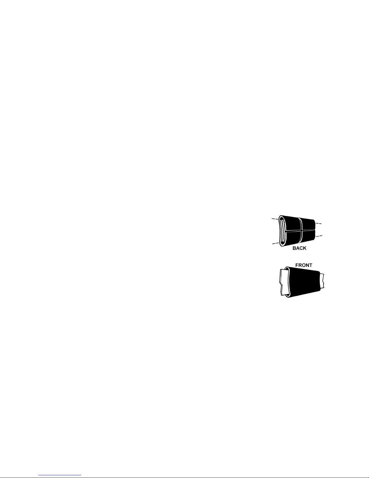
!!!! This tool has a crimp type sealer. A properly made joint will appear as
shown in the illustration. If the joint does not appear as shown, then the
operator must proceed as follows:
A. Insure that the tools operating instructions are
being followed before applying another strap.
B. Cut the strap off and apply another.
If the joint still does not appear as shown, then inspect the tool for worn and/or
damaged parts. Replace tool parts as needed. NEVER HANDLE OR SHIP ANY
LOAD WITH IMPROPERLY FORMED JOINTS. Misformed joints may not secure
the load and could cause serious injury.
!!!! Tuck strap end back into the dispenser when not in use.
CUTTING TENSIONED STRAP
Use only cutters designed for cutting strap; never use claw hammers, crowbars, chisels, axes or
similar tools. Such tools will cause the strap to fly apart with hazardous force. Before using any
Signode product, read its Operation and Safety Manual.
3
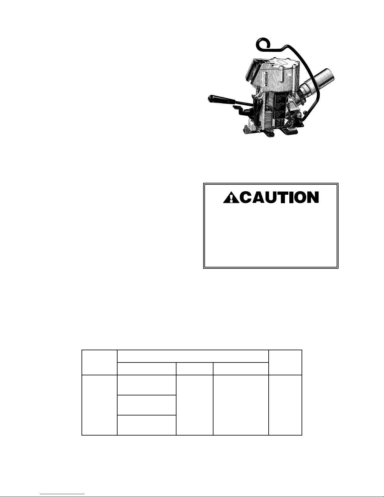
TABLE OF CONTENTS
General Safety Instructions 2
Specifications 4
Pneumatic Information 5
Strap Tension 8
Loading Seals 8
Cutter Adjustment 8
Page
Operating Instructions 9
Joint Inspection 10
Tool:
Parts List & Views 11
Disassembly/Assembly 17
Gear Housing
Parts List & View 20
Disassembly/Assembly 20
Air Motor I8R36:
Parts List & View 22
Disassembly/Assembly 24
Troubleshooting 25
Maintenance 33
Declaration of Conformity 35
AMPT-12
Part No. 422910
DO NOT USE AMPT-12
WITH STEEL STRAPPING
Using strap not recommended for this
tool can result in strap breakage,
improper joint formation and tool
damage.
MODEL
1822,1818,1816
AMPT-12
508,506,504,502
SPECIFICATIONS
STRAP
TYPE WIDTH THICKNESS
Tenax
Contrax
818,816,814
Dymax
1/2"
(12mm)
4
.015" to .030"
(0.4 - 0.8mm)
SEAL
50ASD
PNEUMATIC INFORMATION
AIR PRESSURE REQUIREMENTS
The AMPT-12 tools are designed to operate
at air pressures ranging between 65 and 90
psig (4.5 - 6.2 Bar).
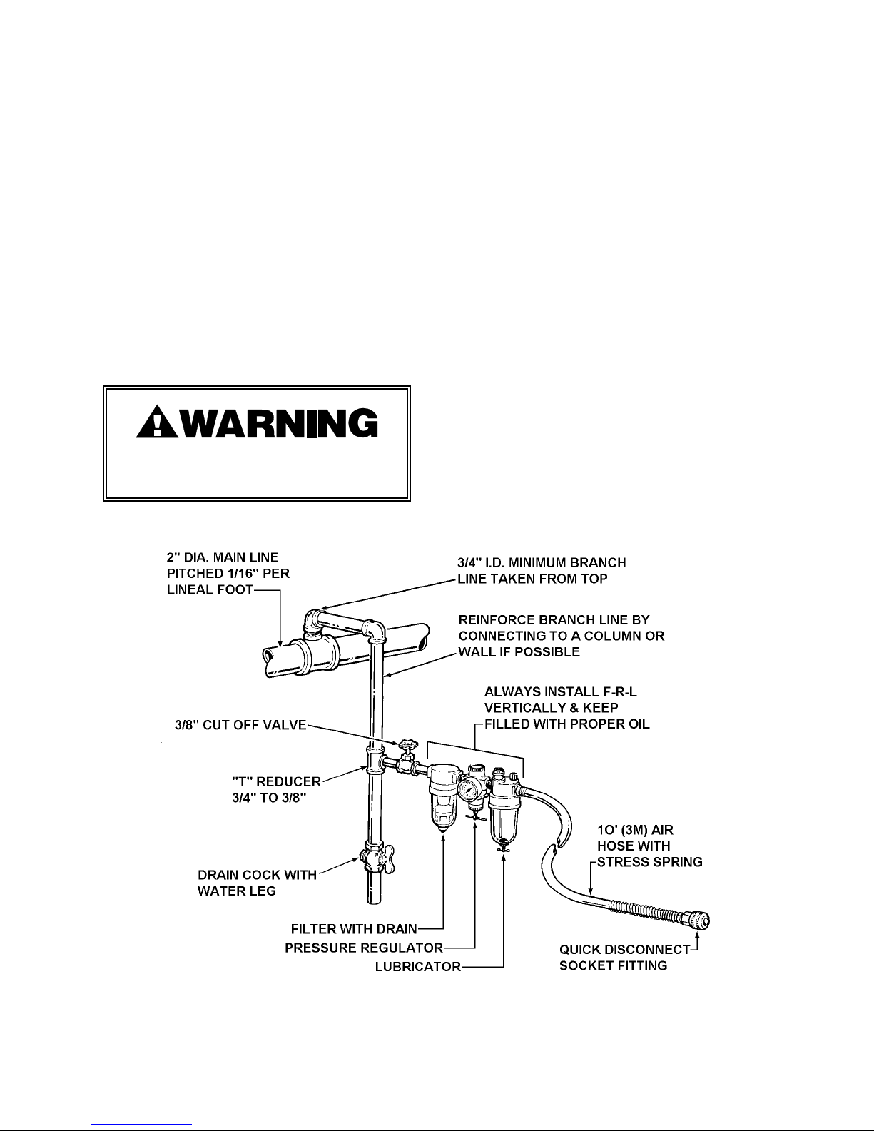
AIR SUPPLY INSTALLATION
If compressor has a good dryer unit, use
black pickled pipe. When a dryer unit is not
installed, use galvanized or copper pipe.
To perform reliably, a pneumatic tool
requires a continuous source of clean, waterfree air at adequate pressure.
Never operate this tool using a
bottled air or gas source.
A filter-regulator-lubricator unit (Signode Part
No. 173111) must be installed as close to the
air tool as possible, preferably within 10 feet.
It should be placed in a convenient location
where it can easily be drained, adjusted, and
filled with oil. The air hose
must have at least a 1/4" I.D. A quickconnect press-on socket is installed on the
stress spring end of the hose for convenient
hookup to the air tool.
Filter and lubricator bowls are made of
polycarbonate material. Do not install where
bowls may be exposed to materials incompatible with polycarbonate. Certain oils,
solvents, and chemicals or their fumes can
weaken these bowls and possibly cause
them to burst. Clean only with warm water.
A cut-off valve placed ahead of the filter will
be useful when cleaning the filter or
replenishing the lubricator.
5

PNEUMATIC INFORMATION, Continued
MOISTURE
Moisture is always present in air lines due to
condensation within the lines as the air
cools. Steps must be taken to remove this
moisture and to keep it from the air tool.
This is because water tends to wash away
lubricants and cause corrosion, sticking and
failure of internal parts.
The main line should be pitched so the far
end terminates in a water leg. Branch lines
are taken from the top of the main, never off
the bottom. Every branch should have a
water leg at its lowest point, with a drain
cock which is drained daily.
If these precautions are taken and water is
still present, an after cooler and a moisture
separator are required between the compressor and the air receiver tank. A large air line
separator can be installed in the air tool line,
but precautions must be taken to insure that
it will be drained daily, before the air tool is
operated.
LUBRICATION
The air motor must be properly lubricated.
This is achieved by keeping the air line
lubricator filled with oil and correctly
adjusted. Without proper lubrication, the
motor will become sticky and the tool will
give low and erratic tension and be difficult
to release from the strap.
Install the lubricator as close to the air tool
as possible. The arrow on the lubricator's
top surface must point in the direction of air
flow.
For proper operation, oil must drop through
the lubricator sight glass at a rate of 1 to 4
drops per minute. This rate is checked while
the air tool is running free. Only 20% of this
oil is actually delivered to the tool. The
remaining oil drops back into the oil
reservoir. The unit is factory set and should
require no adjustment. If an adjustment is
required, the adjusting screw on top of the
lubricator may be turned as marked to
reduce or increase the flow of oil.
Water in air lines is a constant threat to the
proper operation of air tools. Even near
freezing operating conditions, a good
refrigerant type dryer is essential. A good
dryer will remove 95% or more of water right
at the compressor. The remaining moisture
is removed at the water leg in the piping
system or in the filter portion of the F-L-R
(Part No. 173111) unit.
NOTE: Additional information is available in
the Signode publication, "Air Supply Manual"
(Part No. 186038). If you have any questions,
contact your local Signode Representative.
The correct grade of oil must be used in the
lubricator; too heavy an oil will not provide
sufficient lubrication and will cause sticking
and sluggish operation of the air tool.
Recommended oils are any good grade of
rust and oxidation inhibiting oil with a
viscosity of 80-120 S.U.S. at 100 degrees
Fahrenheit. (0.15 to 0.25 cm2 /sec. at 38
degrees Celsius), such as:
Non Fluid Oil Co., grade #LS-1236
Signode oil - Part No. 008556
If necessary, use SAE #5 or SAE #10 nondetergent, cut 1 to 1 with kerosene.
NOTE: Some oils contain anti-wear additives
which may disable the air motor. Be certain
to use recommended oil.
Several drops of lubricator oil added to the
inlet of the air motor or into the air line each
day will help insure good operation. A
noticeable reduction of air motor
performance can usually be corrected by
squirting a few drops of oil into the air line.
6

AIR CONSUMPTION
COLD WEATHER OPERATION
Air consumption in cubic feet per minute
(cfm) for the AMPT-12 can be calculated as
follows:
cfm = (a) x (b) x (0.20)
a = Number of straps applied per minute.
b = Number of seconds motor is on per
strap during tensioning, from start to
deceleration to stall including stall
time while making joint when.
0.20 = AMPT-12 efficiency ratio.
Example Calculation:
Peak strapping load: 4 straps/min. so a = 4
Air motor run time: 5 sec./strap, so b = 5
AMPT-12 efficiency ratio is 0.20
(a)x(b)x(0.20) 6
Air pressure is assumed to be 90 psig (6.2
Bar) with recommended size and length of air
hose. Volume of air is at room temperature
and sea level pressure, or so-called "free air"
conditions. For more detailed information
about air supply systems refer to Signode
manual Part No. 186038.
6 4x5x0.20 = 4 cubic ft/min.
66
If a tool does not operate satisfactorily in
freezing temperatures, certain steps can
correct the problem. The following steps can
be taken to improve cold weather operation
of the tool:
a. An air line dryer adjacent to the
compressor.
b. Use lubricant recommended by Signode.
Signode has tested the use of antifreezes, none work well in air tools; the
tool will gum up when anti-freezes are
introduced and will not function properly.
The best lubricant for freezing weather is
the 1 to 1 oil and kerosene combination.
c. If possible, run the air supply line to a
indoor located Filter-RegulatorLubricator or relocate the F-L-R to a
warmer operating area.
7
STRAP TENSION
LOADING SEALS
The AMPT-12 tools are factory tested to
ensure that at least 350 lbs. (1554N) of
tension is drawn at 90 psig (6.2 Bar).
NOTE: Make sure the input air pressure to
the tool is set between 65 and 90 psig.
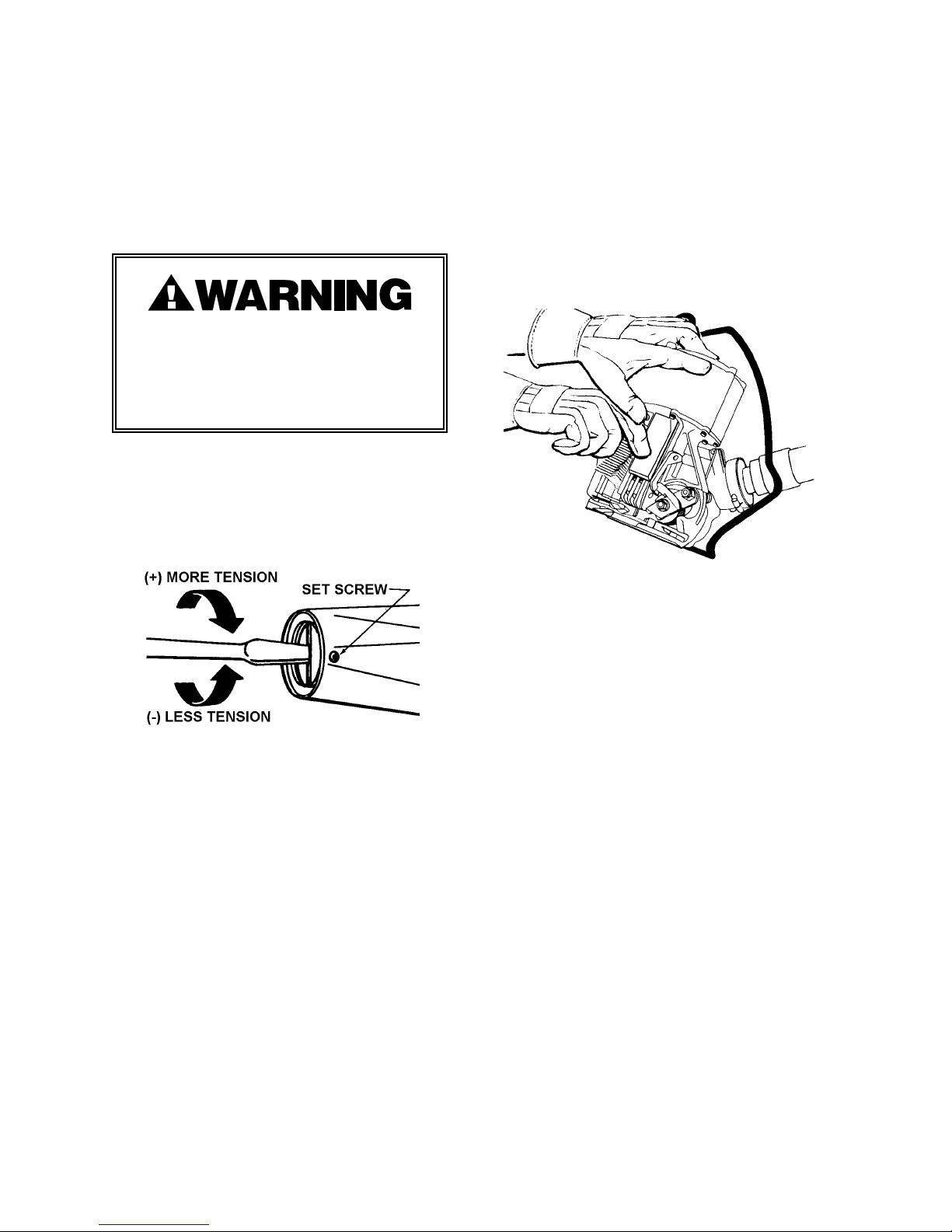
Strap breakage hazard. Strap can break
while tension is being increased. Stand
to one side of the strap as it is being
tensioned. Failure to do so could result
in personal injury.
To adjust the AMPT-58 strap tension, use the
following instrcutions:
1. Loosen the set screw on the side of the
air motor.
To load seals, raise the seal pad assembly
and insert a stack of seals inside the seal
magazine. Release the seal pad. Activate
the sealing mechanism by depressing then
releasing the sealing lever. A seal will be
ejected into the sealing jaws. An extension
on the seal pad closes the top strap loading
slot as a reminder to add seals.
2. Turn the pressure adjustment screw in
increments of 1/8 turns clockwise to
decrease strap tension and counterclockwise to increase strap tension.
3. Turn the adjustment screw until the
desired tension level has been reached.
4. When a satisfactory tension level has
been reached tighten the set screw.
The tool is now set to operate at a given air
pressure in combination with a particular
strap size. Any change in air pressure or
strap size could result in unsatisfactory tool
performance or strap breakage.
CUTTER ADJUSTMENT
If the cutter on the tool does not cut properly,
loosen the shoulder bolt (39) and cap screw
(42), and adjust set screw (44) to remove
clearance between the cutter blade and the
cutter block. Adjust with the jaws in the
down position. Do not over tighten as the
sealing mechanism can be bound by this
adjustment. When adjustment has been
made, retighten the shoulder bolt and cap
screw.
8
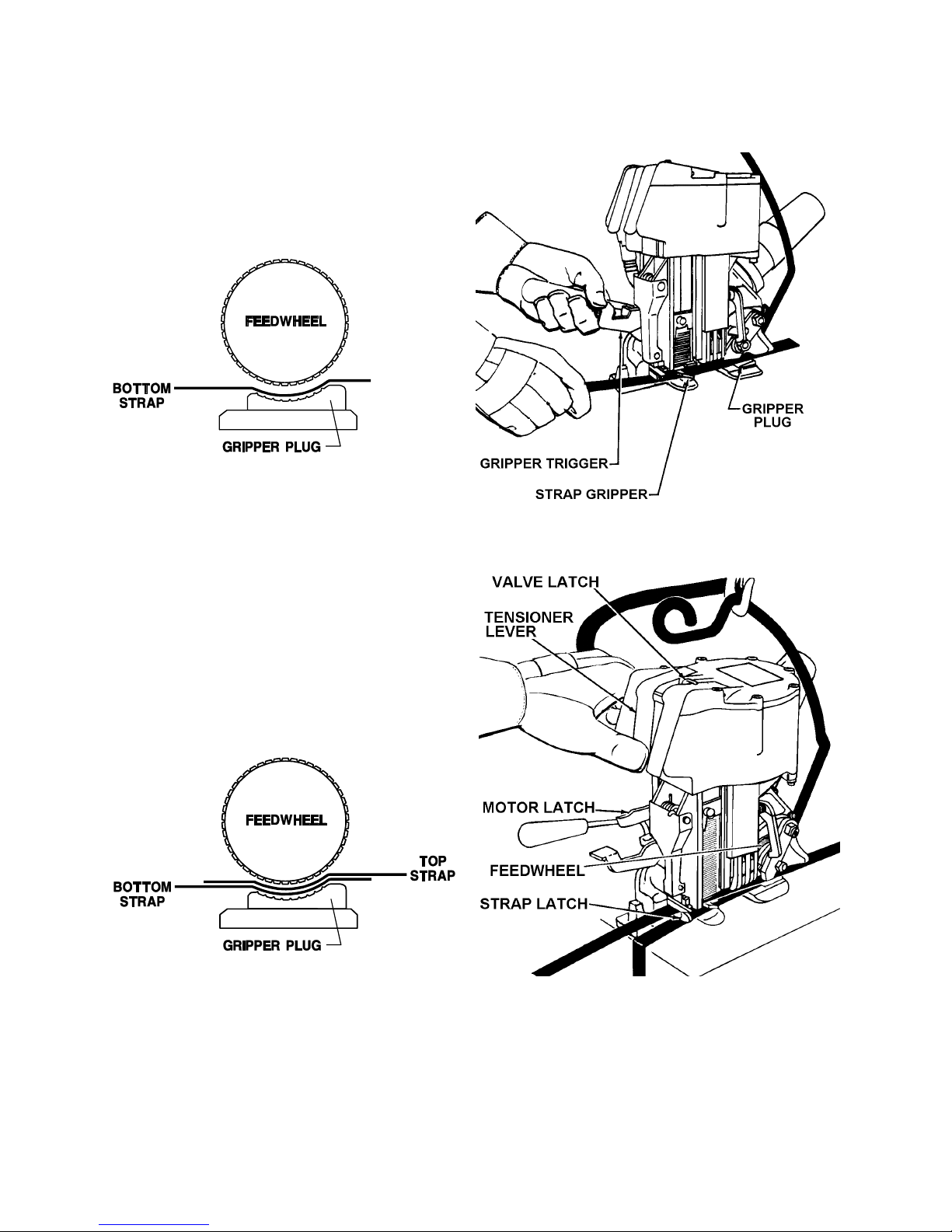
OPERATING INSTRUCTIONS
1. Encircle the package with strap and insert
the bottom end under feedwheel so that it
extends at least 1/2" (12mm) beyond the
gripper plug. Depress the gripper trigger to
actuate the strap gripper.
2. Insert the top strap between the feedwheel
and the gripper plug and insert it into the slot
of the strap latch. Pull excess slack from the
strap. Make sure you are not standing in line
with the strap and press the tensioner lever
all the way down. It will lock in place. The
feedwheel will engage automatically and the
tool will begin tensioning. Should it become
necessary to stop the tensioning cycle, press
the valve latch forward.
NOTE: The feedwheel can be lowered manually, without starting the motor, by pressing the
motor latch. To start the motor, press the tensioner lever.
9

OPERATING INSTRUCTIONS, Continued
3. The motor will stall when the pre-set tension
level has been reached. Press the sealer
lever all the way down, then release. Do not
hold tensioner lever down while pressing the
sealer lever as the tensioning lever will be
released automatically. The tool will
automatically seal the straps together, cut off
the top strap and eject a new seal into the
jaws. Inspect the joint to make sure the tool
has properly crimped the seal.
4. After the tool has sealed and the sealing
mechanism retracts, the feedwheel will
automatically raise off the straps. Swing the
rear of the tool away from the completed tie
to free the tool.
5. If the resulting tension level is not
satisfactory for your strapping needs, then proceed to adjust
the tension as described earlier in this manual.
JOINT INSPECTION
This tool has a crimp type sealer. A properly made joint will
appear as shown in the illustration. If the joint does not
appear as shown, then the operator must proceed as follows:
1. Insure that the tools operating instructions are being
followed before applying another strap.
2. Cut the strap off and apply another.
If the joint still does not appear as shown, then inspect the
tool for worn and/or damaged parts. Replace tool parts as needed.
NEVER HANDLE OR SHIP ANY LOAD WITH IMPROPERLY FORMED
JOINTS. Misformed joints may not secure the load and could
cause serious injury.
10

PARTS LISTS & EXPLODED VIEWS
TOOL HOUSING
KEY DESCRIPTION QTY. PART NO.
1 SHCS, 10-24 x 13/16 11 180600
1A FHSCS, 10-24 x 3/4 1 008757
2 SHCS, 10-24 x 1 2 004061
3 Valve Latch Pin 1 020658
4 Valve Latch 1 020653
5 Valve Latch Spring 1 020654
6 SHSS, 1/4-28 x 7/16 1 004361
7 Tensioning Lever 1 020656
8 Sealing Lever 1 020655
9 Cover 1 020691
10 Valve Lever Pin 1 020671
11 Cover Gasket 1 016906
12 O-Ring 1 020702
14 Piston 1 020648
15 O-Ring 6 020699
16 Tensioner Valve Sleeve 1 020651
17 O-Ring 5 020701
18 Tensioner Valve 1 020652
19 Valve Spring 1 020665
20 Sealer Valve Sleeve 1 020660
21 Sealer Valve Sleeve 1 020657
22 Sealer Valve 1 020731
23 Sealer Valve Spring 1 020725
24 Sealer Valve Sleeve 1 020732
25 Cylinder 1 020734
27 Hansen Plug 1 020704
28 Pipe Bushing 1 008478
29 Elbow 1 020710
29A Tru-Seal, 1-1/4 NPT 1 023087
29B 90° Elbow, 1/4 Tube x 1/4-18 NPS 1 023524
30 SHSS, 1/4-28 x 1/4 1 003465
31 FHSCS, 10-24 x 1/2 2 020729
32 Cover Plate 1 020726
33 Sure-Seal Spring 1 020724
34 Sure-Seal Pawl 1 020727
35 O-Ring 1 020728
36 O-Ring 1 020680
37 Motor Plunger 1 020668
38 Plunger Spring 1 020669
39 Shoulder Bolt 1 024726
40 Roll Pin, 1/8 x 13/16 2 004658
41 Motor Latch 1 020639
42 SHCS, 5/16-18 x 1 1 009016
43 Sealer Frame 1 267632
44 SHCS, 1/4-20 x 1/2 1 023352
45 Roll Pin, 3/16 x 1 1 006787
46 Roll Pin, 3/16x 1-1/2 1 020707
11
 Loading...