

Page 1
AL-12/38
COMBINATION STRAPPING TOOLS
Page 2
READ THESE INSTRUCTIONS CAREFULLY. FAILURE TO FOLLOW THESE INSTRUCTIONS CAN
RESULT IN SERIOUS PERSONAL INJURY.
STRAP BREAKAGE HAZARD
Improper operation of the tool or sharp corners on the load can result in strap breakage during
tensioning, which could result in the following:
! A sudden loss of balance causing you to fall.
! Both tool and strap flying violently towards your face.
Failure to place the strap properly around the load or an unstable or shifted load could result in a
sudden loss os strap tension during tensioning. This could result in a sudden loss of balance
causing you to fall.
! If the load corners are sharp use edge protectors.
! Positioning yourself in-line with the strap, during tensioning and sealing, can result in severe
personal injury from flying strap or tool. When tensioning or sealing, position yourself to one
side of the strap and keep all bystanders away.
TRAINING
This tool must not be used by persons not properly trained in its use. Be certain that you receive
proper training from your employer. If you have any questions contact your Signode
Representative.
EYE INJURY HAZARD
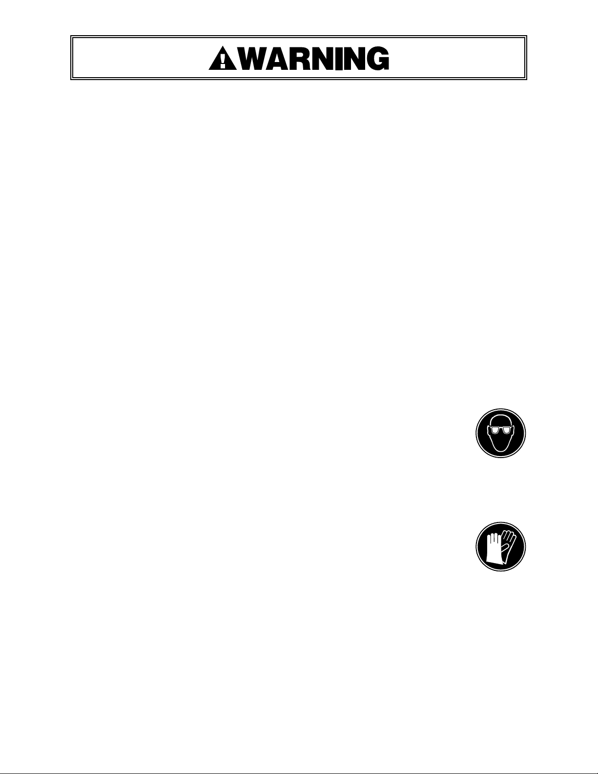
Failure to wear safety glasses with side shields can result in severe eye injury or
blindness. Always wear safety glasses with side shields which conform to ANSI
Standard Z87.1 or EN 166.
FALL HAZARD
Maintaining improper footing and/or balance when operating the tool can cause you to fall. Do not
use the tool when you are in an awkward position.
CUT HAZARD
Handling strap or sharp parts could result in cut hands or fingers. Wear protective
gloves.
TOOL CARE
! Inspect and clean the tool daily. Replace all worn or broken parts.
! Lubricate all moving parts weekly unless otherwise specified.
WORK AREAS
Keep work areas uncluttered and well lighted.
2
Page 3
READ THESE INSTRUCTIONS CAREFULLY. FAILURE TO FOLLOW THESE INSTRUCTIONS CAN
RESULT IN SERIOUS PERSONAL INJURY.
Use correct Signode products for your application. If you need help contact your Signode
Representative.
Signode tools and machines are designed and warranted to work together with Signode strapping and
seals. Use of non-Signode strap and seals and/or manufactured or specified replacement parts may
result in strap breakage or joint separation while applying strapping to a load or during normal
shipping and handling. This could result in severe personal injury.
JOINT FORMATION
! Before using this tool, read its Operation and Safety instructions contained in this manual.
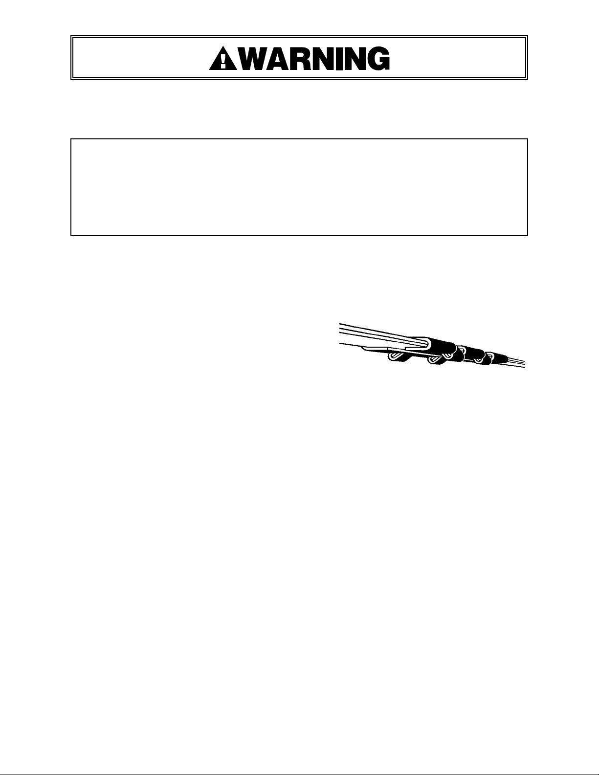
! This tool is a double notch type sealer. Each notch-joint must be inspected to make certain it
has four (4) good notches. A properly formed notchjoint will appear as shown in the illustration. If the
notch-joint does not appear as shown, then the
operator must proceed as follows.
1. Make certain that the tool's operating
instructions are being followed before applying
another strap.
2. Cut the strap off and apply a new strap and seal.
3. An improper formed seal which does not have four (4) good notches, could result in strap
separation. Before moving any package be certain that the seal is formed as shown.
Inspect the joint to make certain it appears as shown in the illustration. If not, remove the
broken strap and check the tool for worn or broken parts. Repair the tool for worn or
broken parts. Repair the tool before applying another strap.
MOVING AND STACKING STRAPPED LOADS
Before moving or stacking any strapped load, follow all standard industry practices regarding safe
material handling procedures.
CUTTING TENSIONED STRAP
Using claw hammers, crowbars, chisels, axes or similar tools will cause tensioned strap to fly
apart with hazardous force. Use only cutters designed for cutting strap. Read the instructions in
the cutter's manual for proper procedures in cutting strap. Before using any Signode product read
its Operation and Safety Manual.
MAINTENANCE
Clean and apply a light weight machine oil to all moving parts on a weekly basis. Clean the
feedwheel daily with a wire brush. Debris accumulated in the teeth of either the feedwheel or the
clutch plug must be removed with a small wire brush. A need to clean the teeth will become
apparent when either the feedwheel skids on the strap or the lower strap slips on the clutch plug
during tensioning.
PACKAGE SURFACE
TABLE OF CONTENTS Page
General Safety Information 2
3
Page 4
Specifications 4
Operating Instructions 5
Tool Parts List 7
Tool Parts Removal, Replacement 9
and Adjustments
Signode tools and machines are designed
and warranted to work together with
Signode strapping and seals. Use of non Signode strap and seals and/or
manufactured or specified replacement
parts may result in strap breakage or joint
separation while applying strapping to a
load or during normal shipping and
handling. This could result in severe
personal injury.
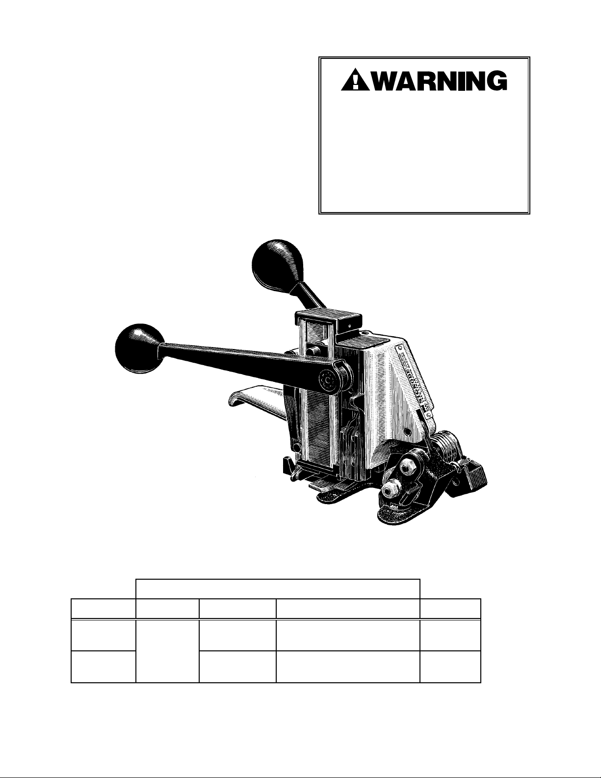
AL-38
Part No. 023380
AL-12
Part No. 023300
SPECIFICATIONS
STRAP
MODEL TYPE WIDTH THICKNESS SEALS
AL-38
APEX
AL-12 1/2"
3/8"
(9.52mm)
(12.70mm)
0.017" (0.43mm) Minimum
0.020" (0.50mm) Maximum
0.017" (0.43mm) Minimum
0.023" (0.58mm) Maximum
38 AL
12 AL
4
Page 5
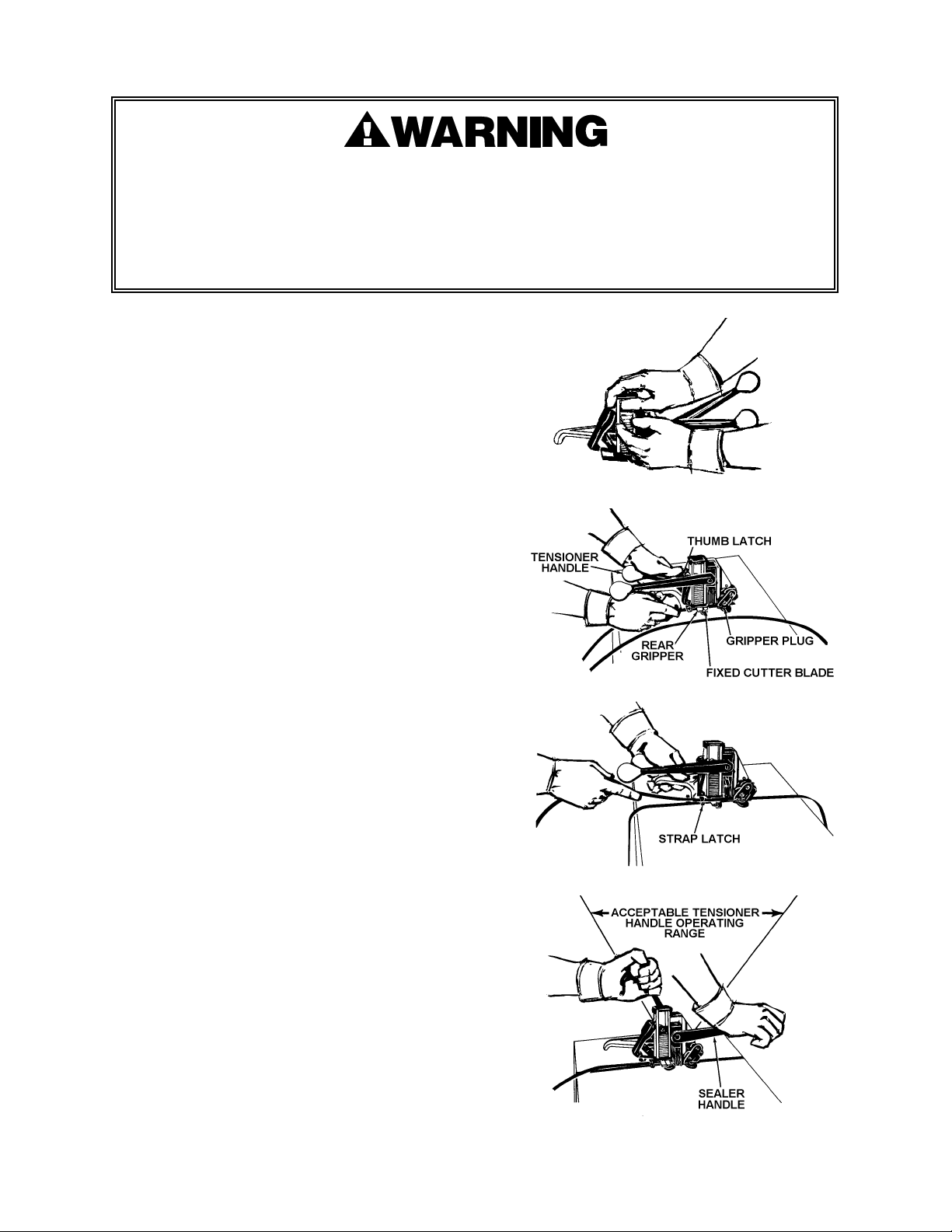
OPERATING INSTRUCTIONS
! Wear safety glasses which conform to ANSI Standard Z87.1 or EN 166.
! Stand to one side of the strap while tensioning. Make sure all bystanders are clear before
proceeding.
! Failure to follow the above could result in serious personal injury.
LOADING SEALS
To load seals, raise the seal pad to the top of the magazine and insert a stack
of seals through the wide opening in the side of the seal magazine.
Make sure the seal stack is pushed all the way in. Seals can be
loaded at any time without waiting for seals to run out. Break a
stack and load as many or as few as needed.
APPLYING A STRAP
1. Encircle the package with the strap. Grasp the
handle of the tool and the tensioner handle with
your left hand. Squeeze the handles together to lift
the feedwheel. Place the strap in the tool so that it
is beneath the fixed cutter blade and the lead end of
the strap covers the gripper plug. Press the thumb
latch to release the rear gripper to hold the bottom
strap in place.
2. Pull out excess slack in the strap. Insert the top
strap above the fixed cutter blade and then insert it
sideways into the strap latch.
3. While standing to one side of the strap line, move
the tensioner handle back and forth, as shown.
Repeat this action until the desired tension is
obtained. Complete the cut-off and sealing
operation by pushing the sealer handle to its
maximum forward position. The rear gripper
automatically opens during this operation. NOTE:
The tensioner handle can be used to help stabilize
the tool during the sealing operation if its pulled
back as the sealer handle is being pushed forward.
The pin that protrudes from the tensioner handle
contacts the sealer plate to prevent the tool from
tipping forward and damaging soft packages.
5
Page 6
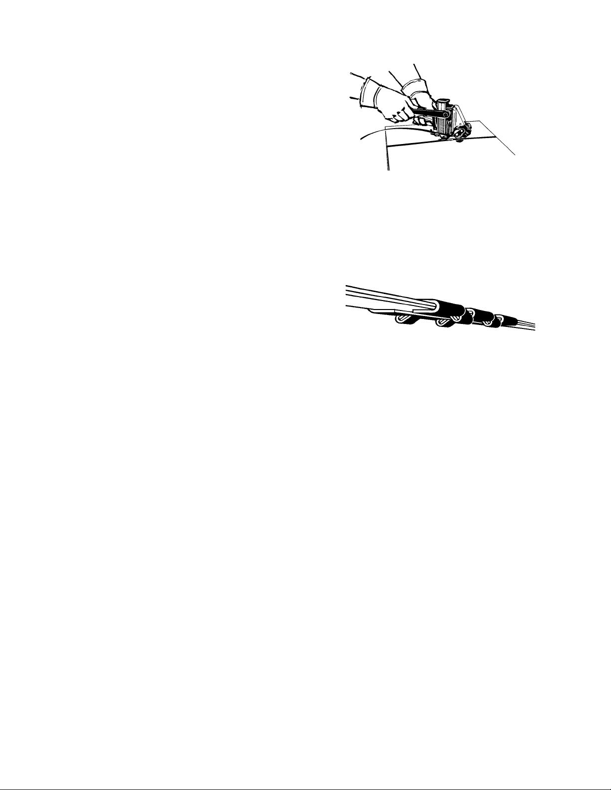
OPERATING INSTRUCTIONS, Continued
4. Return the sealer handle to its original position. At
the same time pull the tensioner handle all the way
back to disengage the feedwheel. The tool can be
removed from the tensioned strap by swinging the
rear of the tool to the operator's left. Inspect the
seal to make sure a proper joint has been formed.
Refer to the view, next page, for details.
JOINT FORMATION
! Before using this tool, read its Operation and Safety instructions contained in this manual.
! This tool is a double notch type sealer. Each notch-joint must be inspected to make certain it
has four (4) good notches. A properly formed notchjoint will appear as shown in the illustration. If the
notch-joint does not appear as shown, then the
operator must proceed as follows.
1. Make certain that the tool's operating
instructions are being followed before applying
another strap.
2. Cut the strap off and apply a new strap and seal.
3. An improper formed seal which does not have four (4) good notches, could result in strap
separation. Before moving any package be certain that the seal is formed as shown.
Inspect the joint to make certain it appears as shown in the illustration. If not, remove the
broken strap and check the tool for worn or broken parts. Repair the tool for worn or
broken parts. Repair the tool before applying another strap.
PACKAGE SURFACE
6
Page 7
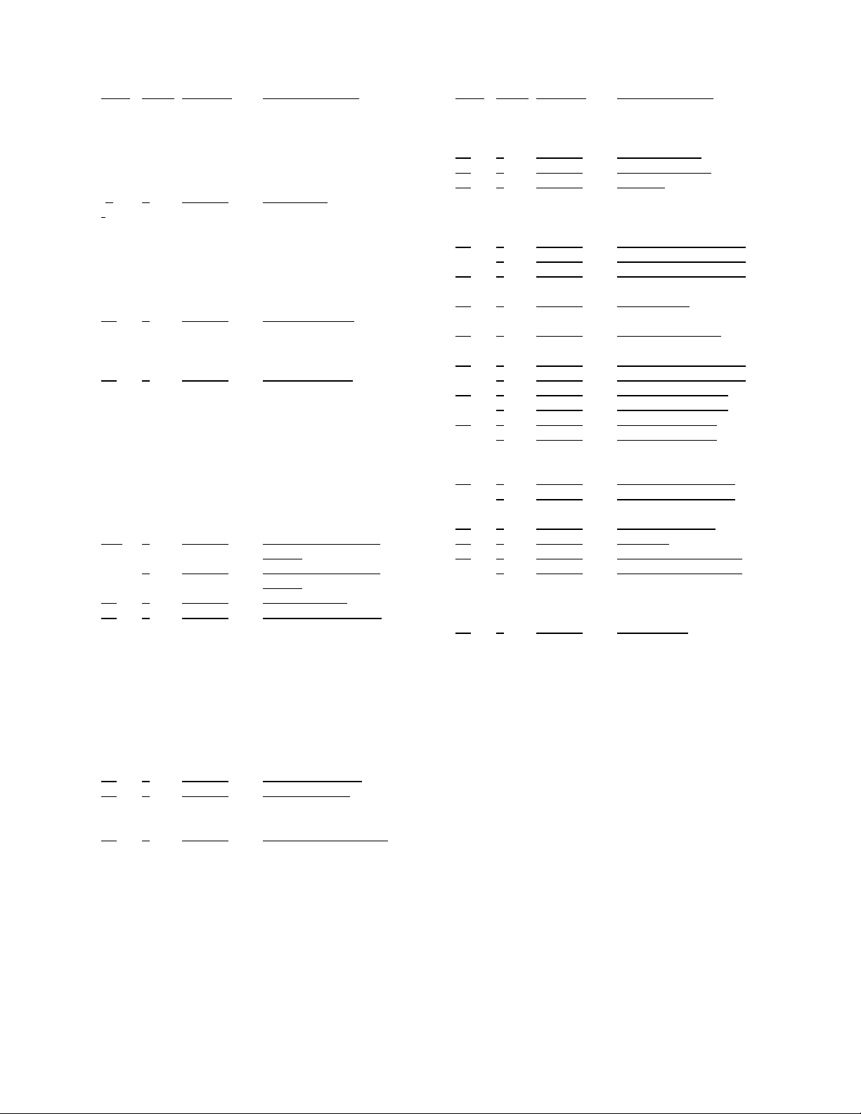
PARTS LIST
KEY QTY. PART # DESCRIPTION
1 1 009041 SHCS, 1/4-20 x 3/4
2 1 008845 SHCS, 5/16-18 x 7/8
3 3 005197 Roll pin, 5/32 x 11/16
4 1 007631 Roll pin, 1/8 x 5/8
5 1 006667 Roll pin, 5/16 x 7/8
6
1 023337 Roller pin
7 1 023336 Cam roller
8 1 023317 Tensioner handle
assembly
9 1 023316 Drive pawl spring
10 1 023314 Driving pawl
11 1 023309 Ratchet gear
12 1 023356 Thrust washer
13
1 023381 Support shaft
14 2 004526 Lock nut, 1/4-28
15 1 023307 Gear housing
bushing
16
1 023379 Gear housing
17 1 023312 Long holding pawl
18 2 023311 Holding pawl spring
19 1 023313 Short holding pawl
20 1 010023 Roll pin, 1/4 x 1
21 1 023308 Feedwheel shaft
22 1 023315 Gear housing spring
23 1 023367 Tensioner frame,
AL-38
1 023366 Tensioner frame,
AL-12
24*
2 008624 Roll pin, 1/8 x 1/4,
AL-38
1 008624 Roll pin, 1/8 x 1/4,
AL-12
25 1 023303 Gripper plug
26 1 023353 Strap latch spring
27 2 009053 SHCS, 1/4-20 x 5/8
28 1 023304 Feedwheel
29 1 023302 Side plate, AL-38
1 023301 Side plate, AL-12
30 1 024444 Guide bushing
31 1 008428 Feedwheel shaft
washer
32 1 008409 L.H. hex nut, 1/4-28
33 1 023352 Set screw,
1/4-20 x 1/2
34
1 023374 Gripper trigger
35 1 023354 Gripper lever
36 1 023371 Gripper spring
37 1 005211 Flexloc nut, 5/16-18
38
1 023376 Seal pad assembly
39 1 020640 Magazine spring
40* 2 004939 Drive screw, #2 x
3/16
41 1 023375 Magazine, AL-38
1 023363 Magazine, AL-12
42 1 023345 Ejector arm pin
43 2 005054 Truarc, #5100-31
KEY
QTY. PART # DESCRIPTION
44 1 006787 Roll pin, 3/16 x 1
45 1 023347 Ejector arm spring
46
1 023343 Ejector lever
47 1 023348 Ejector spring
48 1 023344 Ejector
49 1 014782 Truarc, #5133-18
50 1 023346 Ejector pin
51 1 008148 Roll pin, 1/8 x 7/16
52
1 023365 Cutter block, AL-38
1 023364 Cutter block, AL-12
53 1 023351 Strap latch support
54 1 020662 Strap latch pin
55
1 023349 Strap latch
56 2 009042 SHCS, 1/4-20 X 1
57
1 023355 Holding gripper
58 2 023330 Cutter blade pin
59
1 023389 Cutter blade, AL-38
1 023323 Cutter blade, AL-12
60 4 023359 Outer jaw, AL-38
4 023321 Outer jaw, AL-12
61 2 023332 Notcher, AL-38
2 023361 Notcher, AL-12
62 2 023328 Flat toggle link
63 2 023329 Toggle link
64
4 023360 Center jaw, AL-38
4 023322 Center jaw, AL-12
65 2 023324 Notcher pin
66
2 023326 Toggle link pin
67 2 023325 Jaw pin
68 1 023320 Sealer plate, AL-38
1 023319 Sealer plate, AL-12
69 1 006924 Roll pin, 3/16 x 7/16
70 1 023335 Cam
71 1 023331 Sealer pinion
72
1 023327 Toggle pin
73 1 023334 Rack
74 2 004500 Steel ball, 1/4 dia.
75 1 004485 Rack lock spring
76 1 023318 Jaw support
77 1 023339 Sealer handle ass'y.
79 1 257669 Magazine cap
80 2 004998 Roll pin, 3/32 x 3/8
81 1 171639 Nameplate, AL-38
1 171638 Nameplate, AL-12
82 1 003132 Warning sign
84 1 023368 Sealer frame
!
When ordering parts, please show model,
part number and description.
!
Standard hardware parts may obtained at
any local hardware supply.
!
Recommended spare parts are underlined
and should be stocked.
7
Page 8
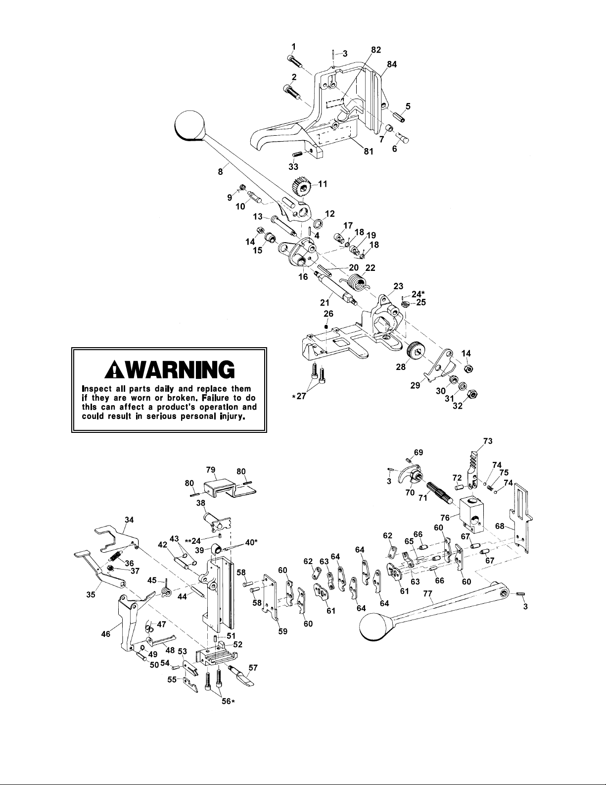
* Use Loctite #242.
** Not required for AL-12 tool.
8
Page 9

PART ADJUSTMENT, REMOVAL & REPLACEMENT
REFER TO PAGES 7 AND 8 FOR ADDITIONAL INFORMATION
DISASSEMBLY OF TOOL:
1. Remove the seals from the magazine and the sealer mechanism.
2. To remove both units loosen the cutter adjustment screw (33) and remove the top and
bottom cap screws in the sealer frame (1 and 2).
3. Push the magazine out to the side so the locating lug clears the offset in the frame. Pull
back the entire sealer mechanism and magazine assemblies, twisting the front outward away
from the sealer frame. Remove both assemblies from the sealer frame.
4. The magazine is now easily separated from the sealer mechanism. The magazine and sealer
mechanisms are now accessible for examination and replacement of worn or broken parts.
The sealer mechanism is serviced by removing the cutter blade pins and cutter blade. Clean
the parts. Jaws and notchers are replaced as required. Note that the outer jaws can be
reversed front to back to provide new cutting edges, doubling the life of these parts. After
necessary repairs have been made, grease the parts or apply light machine oil. The tool is
now ready for reassembly.
REASSEMBLY OF TOOL:
1. Place the sealer mechanism against the magazine and hold the units together.
2. Be sure the strap latch spring (26) is in the correct position in the tensioner frame (23).
3. Insert the lower portion of the assembly into the tool first and hook the slot in the sealer cam
(70) on to the cam roller (7) inside of the sealer frame. Then swing the front of the sealer
mechanism into the sealer frame so that the guide on the jaw support (76) aligns with the
groove in the front of the sealer frame. Then push the whole assembly forward into place
engaging the lug in the side of the magazine into the offset in the sealer frame.
4. Insert and snug up but do not tighten the top and bottom cap screws (1 and 2).
5. With jaws in the down position, advance the cutter adjustment set screw (33) until a slight
bind can be felt when operating the sealer handle.
6. Securely tighten the top and bottom cap screws (1 and 2).
7. Insert a stack of seals into the magazine. Operate the sealer mechanism through 3 or 4
cycles to check tightness of the cutter adjustment set screw and see that the seals feed
properly. If the sealer mechanism is excessively tight, back off the cutter adjustment set
screw slightly. Next, apply a strap under tension to be sure that all elements of the tool
operate properly.
EJECTOR (48) AND EJECTOR LEVER (46) W/O MAGAZINE REMOVAL:
1. Remove the seals from the magazine.
2. Remove the Truarc (43) from the right side of the ejector arm pin (42).
3. Lift the sealer handle to clear the ejector arm pin (42).
4. Drive out the ejector arm pin (42) from the sealer handle side.
5. Remove the ejector arm spring (45).
6. Place the sealer mechanism in the UP position with the sealer handle in the rest position.
7. Hold the gripper lever (35) down and pull out the ejector lever.
EJECTOR DISASSEMBLY
1. Drive out the roll pin (49) from the ejector pin (50). Be sure to support the ejector lever (46).
See Figure 7.
2. Remove the pin (50), ejector (48), and spring (47). Replace the ejector lever and/or ejector as
necessary.
3. Reassemble with the new ejector by following these steps in reverse order.
NOTE: If only the ejector needs to be replaced, it can be removed without removing the ejector
lever following the above 3 steps.
. . . Continued
9
Page 10

PART ADJUSTMENT, REMOVAL & REPLACEMENT, Continued
REFER TO PAGES 7 AND 8 FOR ADDITIONAL INFORMATION
REASSEMBLE THE EJECTOR LEVER (46):
1. Insert the ejector (48) into the cutter block (52) slot, hold the gripper lever (35) down and
slide the ejector lever (46) into position.
2. Start the ejector arm pin (42) through the left side of the ejector lever (46) and magazine.
3. Insert ejector arm spring (45) and maintain alignment with a punch from the sealer handle
side.
4. Tap ejector arm pin (42) in from the tensioner handle side, while removing the aligning
punch at the same time.
5. Push on the lower left part of the ejector lever (46) to align holes on the right side of the tool.
Finish tapping in the ejector arm pin (42) and replace the Truarc (43).
6. Insert a stack of seals into the magazine. Operate the sealer mechanism through 3 or 4
cycles to check the tightness of the adjustment set screw and to see that the seals feed
properly. If the sealer mechanism is excessively tight, back off the cutter adjustment set
screw slightly. Next, apply a strap under tension to be sure that all elements of the tool
operate properly.
REPLACING THE FEEDWHEEL:
To change a dirty or worn feedwheel remove the left hand nut (32) from the feedwheel shaft and
the lock nut (14) from the support shaft. Press down on the tensioner handle to raise the
feedwheel and remove the washer (31), side plate (29) and feedwheel (28). Replace the feedwheel
and reassemble the parts in reverse order.
REPLACING THE GRIPPER PLUG:
Turn the tool on its side. Remove the feedwheel by following the Feedwheel Replacement
Instructions. Using a punch, drive the plug (25) and roll pin (24) upward and out. Make certain a
roll pin is properly installed in the new gripper plug. Drop the new gripper plug, with roll pin, into
the hole in the base, properly aligning the roll pin with its hole. Drive the gripper plug downward
with a length of brass rod or re-install the feedwheel and apply a strap under tension to fully set
the plug.
10
Page 11

11
Page 12
SIGNODE
NEW TOOL WARRANTY
Signode Engineered Products Warrants that a new Signode strapping tool will operate per functional
specifications for a period of sixty (60) days after the date of shipment to the owner's place of business.
Normal wearing parts, as outlined in the Operation, Parts & Safety manual, are covered by a thirty (30) day
warranty unless, in Signode's judgement, these parts have been subjected to abnormal or extreme usage.
Signode's sole liability hereunder will be to repair or replace, without charge, F.O.B. Signode's Glenview,
Illinois plant, any tool which proves to not operate per functional specifications within the stated period.
Signode reserves the right to replace any tool which proves not to operate per functional specifications
with a new or like-new tool of the same model if in Signode's judgement such replacement is appropriate.
Any new replacement tool provided to an owner will carry a full sixty (60) day warranty. Any warranty
repaired tool or like-new replacement tool will carry a warranty for the balance of the time remaining on the
initial sixty (60) day warranty. This warranty will be extended to compensate for the time the tool is in
Signode's possession for warranty repairs.
This warranty is void as to any tool which has been: (I) subjected to mis-use, misapplication, accident,
damage, or repaired with other than genuine Signode replacement parts, (II) improperly maintained, or
adjusted, or damaged in transit or handling; (III) used with improperly filtered, unlubricated air or improper
strapping material, (IV) in Signode's opinion, altered or repaired in a way that affects or detracts from the
performance of the tool.
SIGNODE MAKES NO WARRANTY, EXPRESSED OR IMPLIED, RELATING TO MERCHANTABILITY,
FITNESS OR OTHERWISE EXCEPT AS STATED ABOVE AND SIGNODE'S LIABILITY AS ASSUMED ABOVE
IS IN LIEU OF ALL OTHERS ARISING OUT OF OR IN CONNECTION WITH THE USE AND PERFORMANCE
OF THE TOOL. IT IS EXPRESSLY UNDERSTOOD THAT SIGNODE SHALL IN NO EVENT BE LIABLE FOR
ANY INDIRECT OR CONSEQUENTIAL DAMAGES INCLUDING, BUT NOT LIMITED TO, DAMAGES WHICH
MAY ARISE FROM LOSS OF ANTICIPATED PROFITS OR PRODUCTION, SPOILAGE OF MATERIALS,
INCREASED COSTS OF OPERATION OR OTHERWISE.
Considerable effort has be made to ensure that this product conforms to our high quality standards.
However, should you experience any difficulties, please contact your Sales Representative providing
samples and the manufacturing code specified on the tool.
Thank you for your help.
SIGNODE ENGINEERED PRODUCTS
Hand Tool Division
3620 W. Lake Avenue, Glenview, Illinois 60025
© Copyright 2001, Signode 186026 Rev. 7/2001
 Loading...