

Page 1
PLASTIC STRAPPING HEAD
MODEL AK200HDX-19 / 25 / 32 mm
Serial N° 09/2008 SN3627
As at : 28 March 2011
It is the customer’s reponsibility to have all
operators and servicemen read and understand
Contact your local Signode representative for
IMPORTANT!
DO NOT DESTROY
this manual.
additional copies of this manual.
OPERATION, PARTS AND SAFETY MANUAL
Page 2
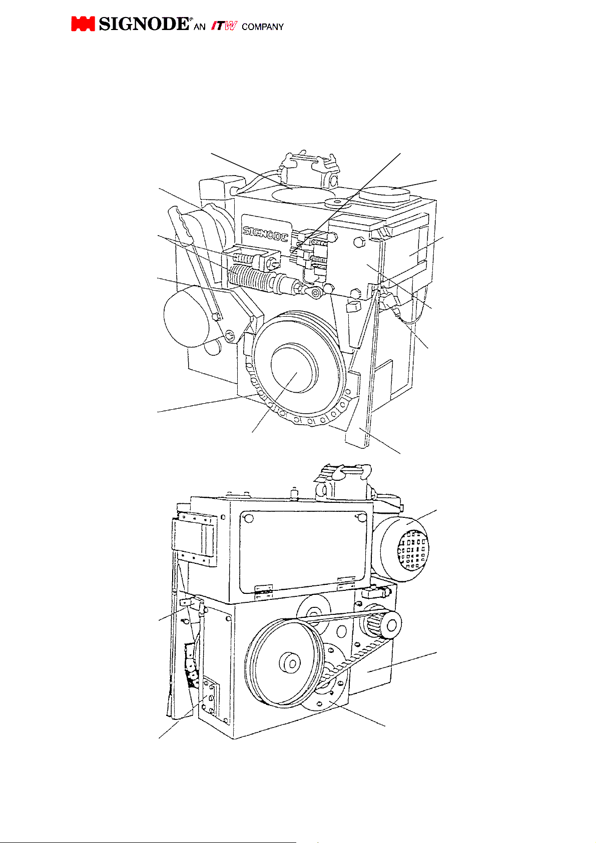
Air blowing
SIGNODE AK200-HDX
Basic Operating and Adjustment Instructions
Drive motor
Disk washer
with aux. spring
Strap entry chute
Back-up
roller chain
Strap stop
switch
Holding brake
cam shaft
Cam shaft
Feed wheel
Sealing punch polder
Weld Motor
Pusher
(cover plate)
Sealing
Mechanism
device
Strap guide wedge
Drive motor
Transmission
Drive motor
1
Page 3
4.
1.
Keep your Operation, Service and Safety
ADDITIONAL SAFETY INSTRUCTIONS ARE LOCATED THROUGHOUT THIS
GENERAL SAFETY
This manual gives you information on how to operate and maintain your Signode Power
Strapping Machine.
Only trained personnel should operate or service machine.
Read these safety instructions before operating or servicing your machine.
OPERATING MACHINE
BEFORE
1.
Read the operating instructions.
2.
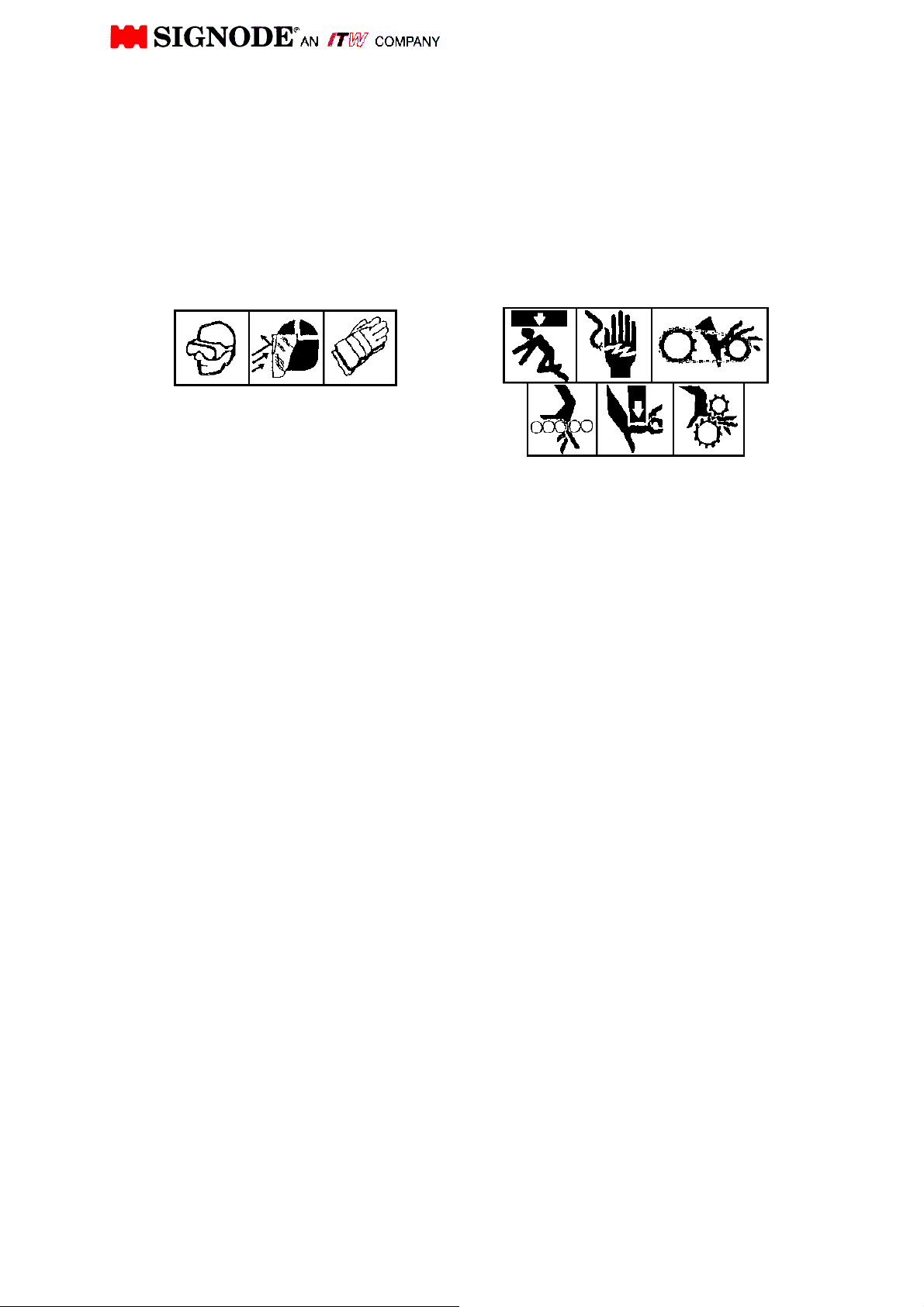
Wear eye or face, and hand protection.
3.
Inspect the machine for unsafe conditions
DAILY and replace any worn or broken
parts.
Check that all guards are in place and all
safety devices are working properly. Do not
operate machine with any safety devices
removed.
5.
Make sure machine is clear of all tools, debris
and other objects not related to machine
function.
DURING
1.
Do not wear loose clothing or jewelry.
2.
Never put any part of your body into, under or
near moving machinery.
3.
Keep hands out of the strap chute area.
AFTER
1.
Shut off all electric an air power.
2.
Remove all tools, debris, and other objects
from machine area.
2.
3.
4.
5.
6.
ADDITIONAL CONSIDERATIONS
To insure proper operation of machine,
Do not overload machine by exceeding
SERVICING MACHINE
Shut off and lock out electric and air
power.
Remove packages from machine.
Do not stand or walk on conveyor service
machine.
Follow the maintenance instructions in
your manual.
Use the correct tools to repair machine.
Never adjust, repair or oil moving
machinery.
use the specified electric and/or air
power sources.
Signode's recommended performance
limitations.
Do not attempt to after machine design
unless written approval is received from
Signode Corporation.
Manual at your machine. Refer to it -
often.
Read all of the signs on
machine.
Do not remove any
signs from machine
Replace all missing or
damaged signs.
MANUAL. THEY SERVE TO WARN THE OPERATOR AND SERVICEMAN
ABOUT POTENTIALLY HAZARDOUS SITUATIONS.
2
Page 4
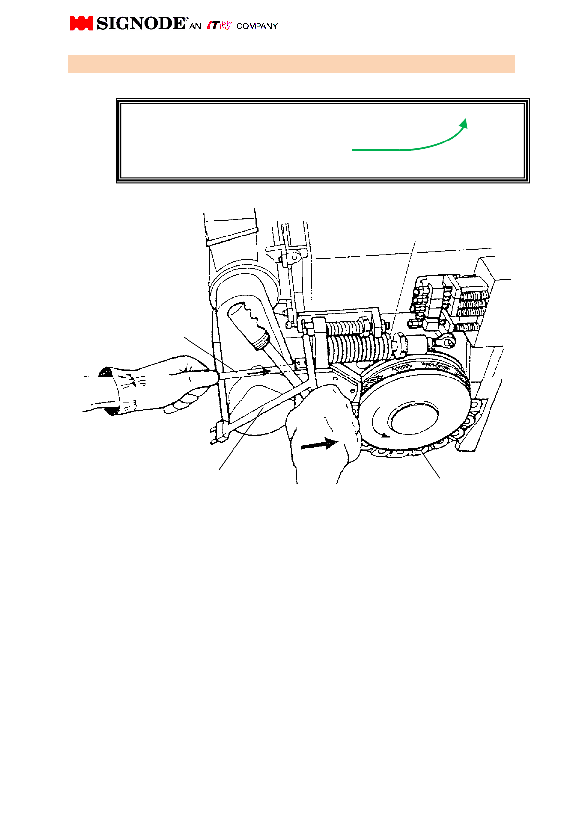
Important Caution!
1. Insert strap
To prevent strap jams natural strap curl
in the direction shown (with the curl up)!
Disk Washers
Strap
Cam Shaft Wrench
Part No. 0460605
Back-up roller Chain
Release tension of the back-up roller chain by compressing the stack of disk washers
with the cam shaft wrench.
Push the strap into the strap guide channel until it meets resistance, then insert strap
into the head using operating mode.
Wear gloves!
3
Page 5
Part No.: 0460605
(cover plate)
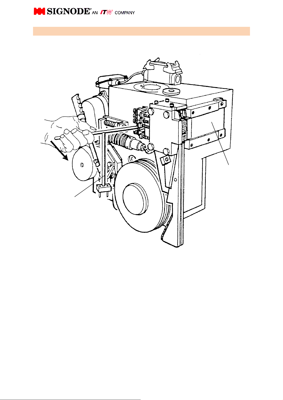
2. Opening of pusher (by hand)
Cam shaft wrench
Insert the camshaft wrench into the hole at the end of the pusher lever and move it
towards the right.
The pusher opens and exposes the die holder and vibrator for inspection and
cleaning.
Pusher
4
Page 6
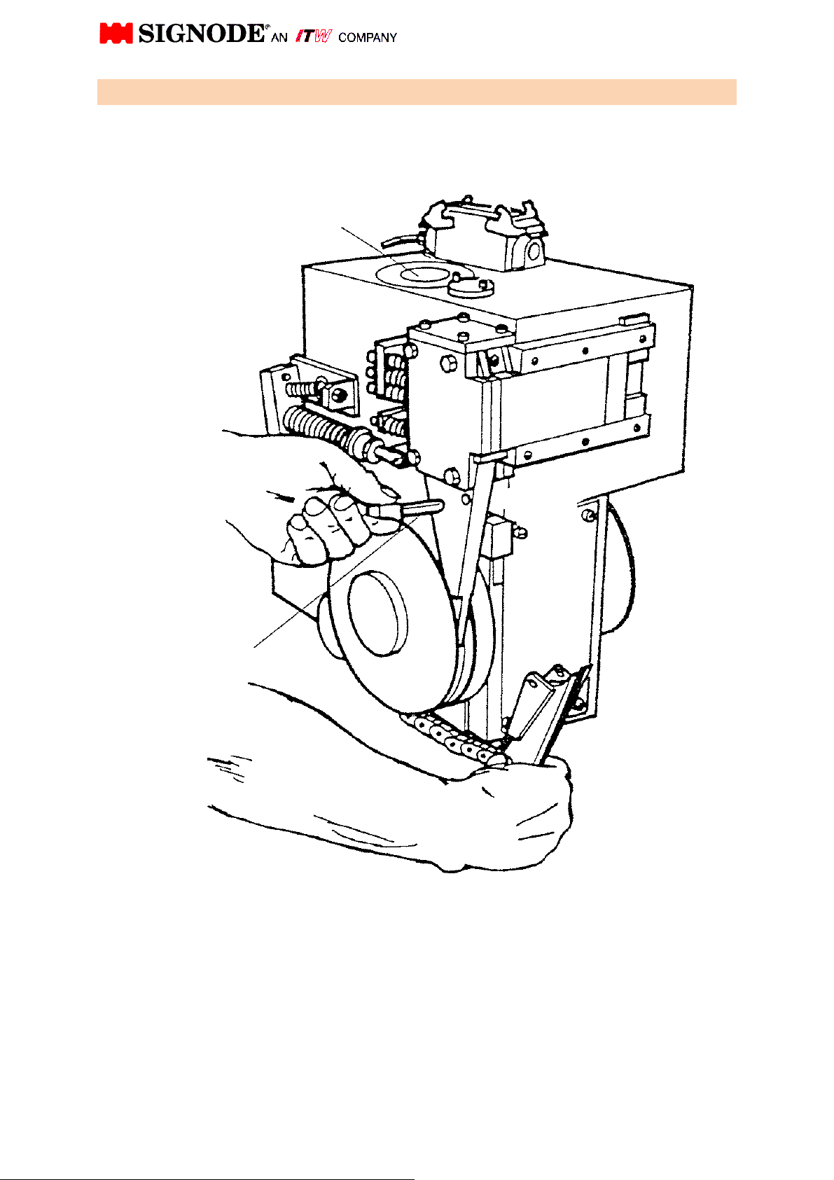
3. Disengage back-up roller chain
To clean the strap guide channel, to remove pieces of strap and to turn the cam shaft
by hand, the back-up roller chain must be disengaged.
First of all, release the back-up roller chain and pull out the pin.
Then disengage the complete chute wedge with the chain.
Pin
Cam shaft
5
Page 7
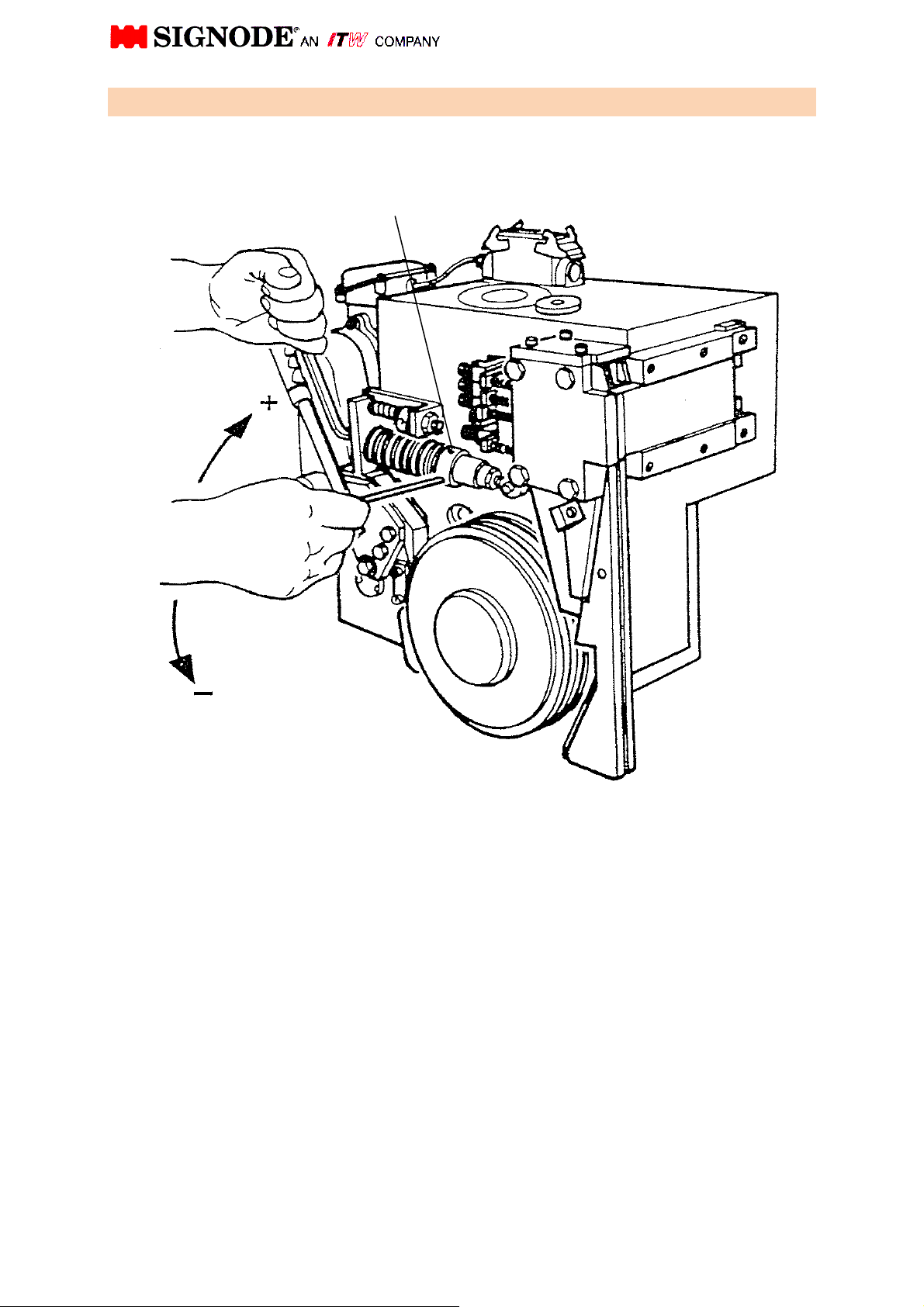
Adjustment screw
4. Strap tension adjustment
Strap tension is increased by turning the adjustment screw clockwise and decreased
by turning it counter-clockwise.
If an extreme low strap tension is desired, you may reduce the disk washers and add
on compression spring. Refer to your instruction manual under chapter "disk washer".
(Drawing-No. 100.07 soft)
6
Page 8
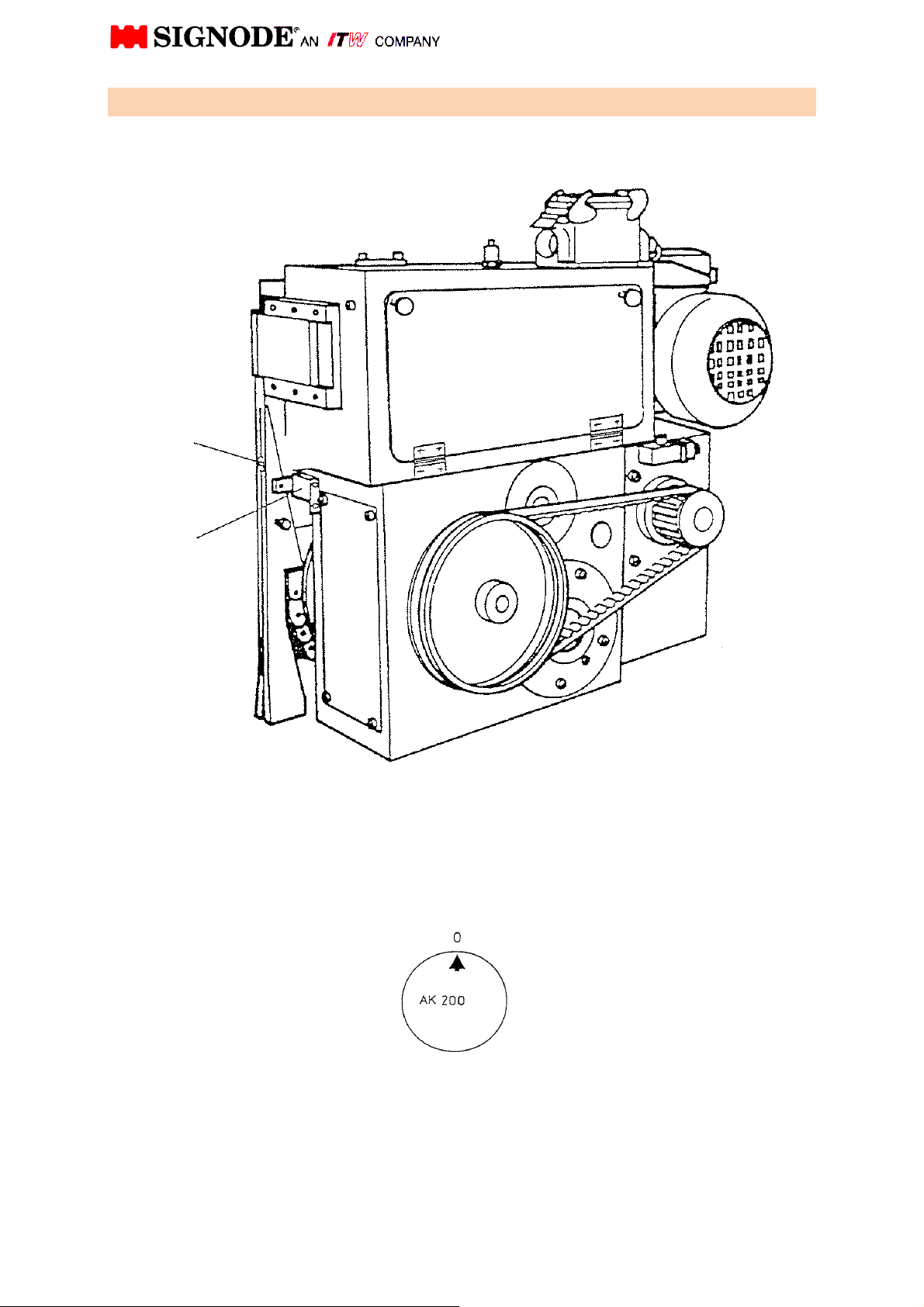
5 Function of the Proximity switch (strap Stop switch)
Switch actuator
B102 Proximity Switch
“strap stop
With no strap present, the strap Stop switch is not actuated.
Strap passing the switch actuator pushes the same down, energizing the proximity
switch (B102 Strap stop Proximity switch)
”
Cam shaft position: 0
7
Page 9
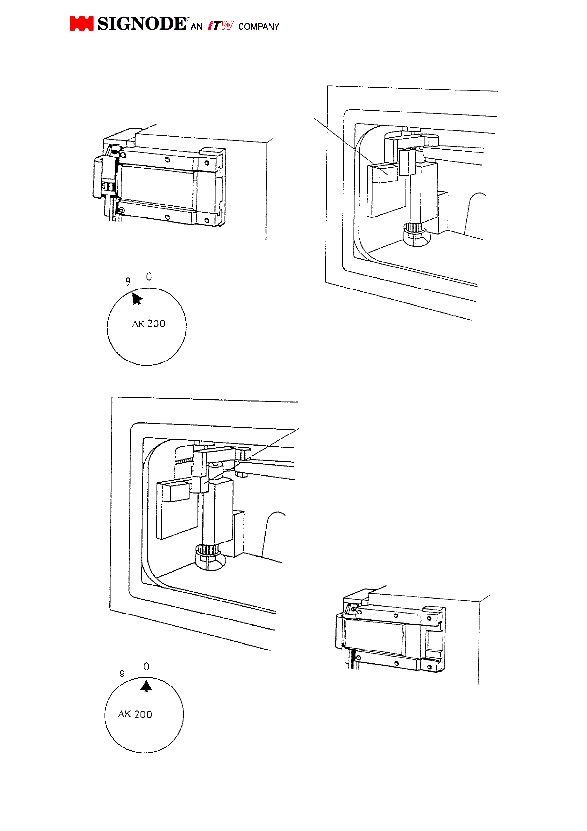
5.1 Function of proximity switch B103 & B104 “ pusher open / closed”
B103 Proximity switch "pusher
open"
Energized (diode lit)
Pusher fully open
Cam shaft position: 9
B104 Proximity switch "pusher
closed"
Energized (diode lit)
Pusher closed
Cam shaft position: 0
8
Page 10
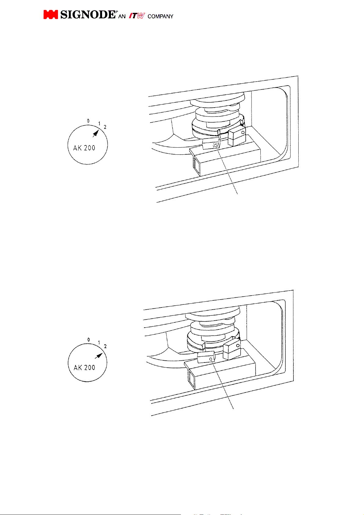
before 2
slow tension
behind 2
"Pre
-
Tension reached"
"Pre
-
Tension reached"
5.2 Function of proximity switch B105
switching from high speed to slow speed tension
Switching energized =
high speed tensioning
(diode lit)
Cam shaft position:
Not energized =
Cam shaft position:
B105 Proximity switch
B105 Proximity switch
9
Page 11
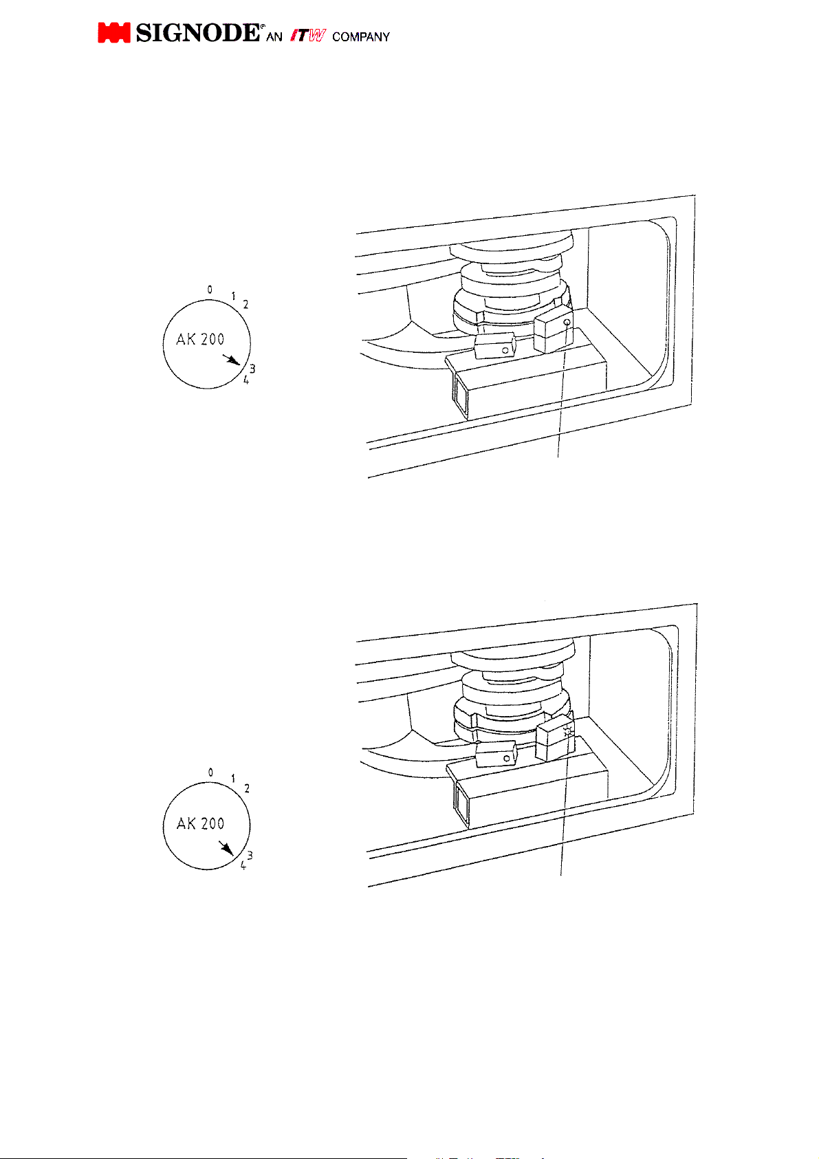
"Final
-
tension reached"
"Final
-
tension reached
"
Strap tension is
5.3 Function of proximity switch B106
switch for brake "final tension reached"
Not energized =
strap is being
tensioned (slow)
Cam shaft position: at 3
Energized (diode lit) =
Cam shaft position: at
B106 Proximity Switch
B106 Proximity switch
10
Page 12
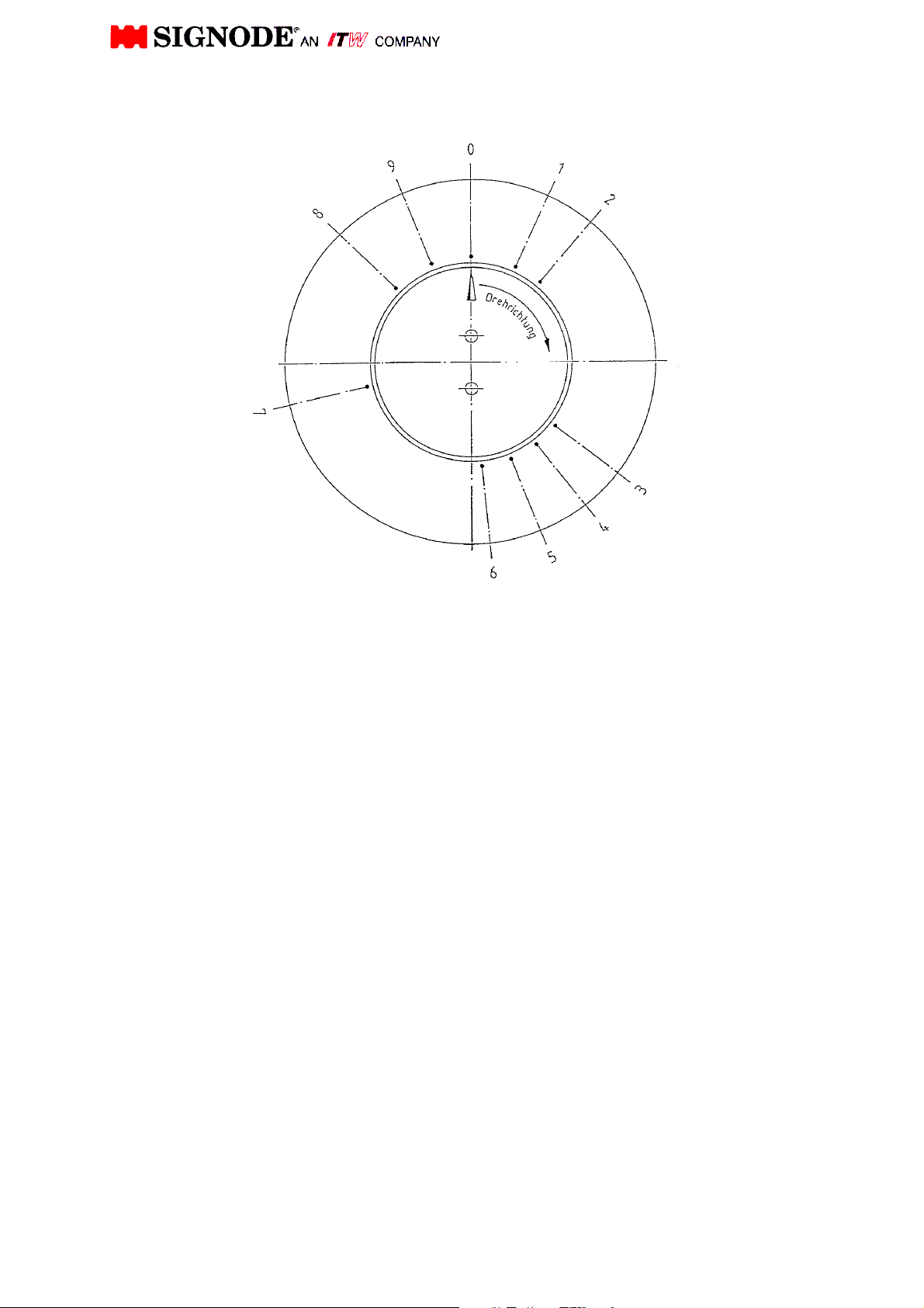
TENSION AND SEALING PROCEDURE
0. Home position proximity switch B104 "shutter close" activated. Shutter closed.
1. Tip of strap is clamped. Proximity switch B106 "max. strap tension reached" will
be activated for the first time.
2. Proximity switch B105 "Pre- tension reached" will be free Switching into tension
slow speed.
3. Strap will be tensioned. Proximity switch B106 "max. strap tension reached" will
be de-activated again.
4. Maximal strap tension reached, cam follower is on highest point of cam. The
spring package is pressed together to its maximum for maximum pre-set strap
tension. Starting strap end clamped. Proximity switch B106 strap tension
reached will be occupied for the second time. Strap drive brake Y36 will be
connected.
5. Loop grip presses firmly both straps. Tip of strap and strap end clamped.
Proximity switch B105 "Pre-tension reached" will be activated again strap
slacken for cut off at no load starts.
6. Weld motor starts and strap will be cut. Proximity switch B105 "pre-tension
reached" will be free again.
7. Cool off joint. Pressing together both straps at camshaft strap. Proximity switch
B105 "Pre-tension" will be activated for the second time.
8. Vibrator, loop grip and gripper in home position. Proximity switch B104 "Shutter
close" will be free. Shutter starts opening.
9. Proximity switch B103 "Shutter open" is occupied and proximity switch B105
"pre-tension reached" will be free again. Shutter fully opened.
11
Page 13

SERVICE AND MAINTENANCE MANUAL
FOR STRAPPING HEAD
MODEL
AK200-HDX-19 / 25 / 32 mm
Page 14

T A B L E O F C O N T E N T S
Section Page
General
Technical Specifications
Sequence of Operation
Positions on Camshaft Display
Preventive Maintenance
Parts Removal and Replacement
Head Adjustments
Trouble Shooting
Recommended Spare Parts List
Remote Spare Parts List
Conversion Kit AK200-
Sub-Assembly Drawings & Parts List
HDX auf 32 mm / 25 mm / 19 mm
464631 Version 32 mm
Strapping Head
464624 Version 25 mm
464618 Version 19 mm
1 1
2 2
3 3
4 10
5 13
6 14
7 17
8 20
9 25
10 28
31
11 32
33
464655 Version 32 mm
Sealing Mechanism
464656 Version 25 mm
39
464657 Version 19 mm
Transmission - 15 -
Strap Drive
Brake
Intermediate Shaft
Camshaft
"Camshaft Brake"
Spring Assembly
Insert Guide with Spring
Strap Guide Wedge
Air Blowing Device
100.36 43
464626 47
100.14 50
464291 52
464613 54
150.15 56
100.07 58
464643 60
464636 62
464269 64
Electrical Plans
Installation
1 Plug Wiring 65
Option:
2 Plugs Wiring 66
Page 15

1. GENERAL
The SIGNODE AK200 Plastic Strapping Head is designed to be used for applying various
qualities of plastic strapping fully automatically.
The head is only part of the strapping installation, which consists of the main structure, chute
system and control panel.
In order to ensure trouble free operation it is important that all operation and maintenance
personnel have received adequate instruction about the operating sequence of the head.
Furthermore, it is important that all will be familiar with the operation and maintenance manual
as supplied with the strapping head.
When operating and maintaining the head, it is important to regard all safety regulations valid in
the country of operation and supplied by the appropriate safety board or organization.
NOTE:
Before starting the head, check feeding direction of strap drive.
For a long lifetime of the feed wheel ring, it is important that the feed wheel ring does not run
without strap during strap threading. The strap feed control time depends on the strap chute
size and must be set as short as possible (max. 0.5 sec longer as necessary to fill up the strap
chute).
The tension control time must always be set shorter than the overall feeding time so that the
strap cannot escape out of the head, and that always strap rests between feed wheel ring and
roller chain, see adjustments of roller chain 7.6 , page 19.
1
Page 16

2. TECHNICAL SPECIFICATIONS AK200-HDX
Strapping Width: 32 mm; 25 mm; 19 mm
Strap Thickness: 0,5 - 1,3 mm
Joint Strength: Depends on individual strap
size and strap quality
Feed and Take Up Rate: 1,25 m/sec. (high)
0,07 m/sec. (slow)
Tension: max. 6000 N / adjustable
Min. Package Face: approx. 150 mm
Joint Time: approx. 4,5 seconds
incl. 2 sec. cool-off time
Weight: 95 kg
Power Source: 400 V, 3 Ph, 50 Hz
CAUTION! In case of different motor connection!
(for USA 270 / 480 V, 3 Ph, 60 Hz)
Control Voltage: 24 V
Weld Motor: 230 V, 50/60 Hz
2
Page 17
3. SEQUENCE OF OPERATION
3.1 GENERAL
The SIGNODE AK200-HDX is electrically powered and electrically / electronically controlled.
Only one power source is needed to operate the head.
The sequence of operation consists of two major functions. These are:
- First "Strap Feeding"
- Second "Strap Take up", "Strap Tension", "Strap Sealing"
Both functions can be operated on the control panel manually by inching push button.
In addition the function "Shutter Open/Closed" can also be operated manually by inching push
button.
Because of the high resistance from the tension cam it is not possible
to turn the camshaft by hand.
If it necessary to turn the camshaft by hand. Please disconnect first the
strap guide chain.
Remove the release pin (see Rep.58, figure 0464631, page 33) and
swing strap guide wedge inclusive chain (see Rep.10, figure 0464631,
page 33) backwards.
Also please swing out the stop device by pull off the catch pin
(voir Rep.14 + 15, figure 0464643, page 60)
3
Page 18
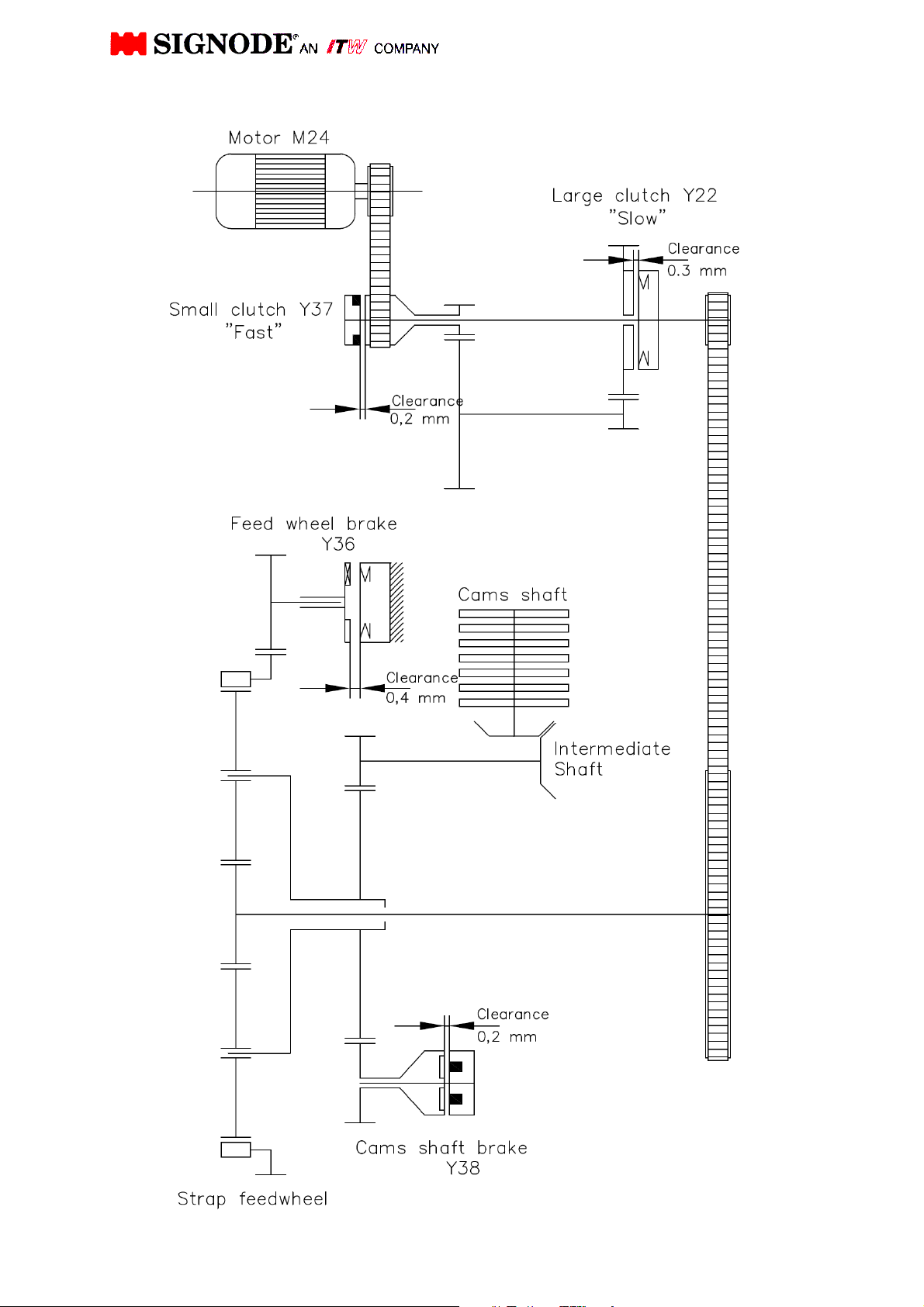
Strapping head drive (allegory)
4
Page 19

3.2 Table of contents
M 24 = Motor
M 28 = Weld Motor
Y 37 =
Y 22 =
Y 36 =
Y 38 =
Small clutch 15 Nm ,
« transmission Fast »
Large clutch 60 Nm
« Transmission Slow »
Electro-Magnetic Brake
"Strap Drive"
Electro-magnet brake
«Camshaft»
See drawing
464631, Rep. 82
See drawing
464631, Rep.83
B102 =
B103 =
B104 =
B105 =
B106 =
B183 =
Proximity Switch
«Strap stop» (Strap Feed Stop)
Proximity Switch
« Shutter open»
Proximity Switch
« Shutter close »
Proximity Switch
« Pre-tension reached »
Proximity Switch
« Final Tension reached »
Proximity Switch
« Strap Disturbance and Strap cutting at no load »
See drawing :
464631, Rep. 76
See drawing :
464631, Rep. 77
See drawing :
464631, Rep. 78
See drawing :
464631, Rep. 79
See drawing :
464631, Rep. 80
See drawing:
464631, Rep. 81
5
Page 20

3.3 Operation Description
(See section 4, simplified view)
The strapping head is in home position. The camshaft display indicator is on - 0 - position, and
the camshaft is blocked against rotation in anti-clockwise direction further than the - 0 - position
on the camshaft display. The switch B104 is activated, indicating that the shutter is closed.
With start of the strap cycle program, strap feeding will be initiated. While strap feeding the
motor M24 (see drwg. 464631, pos. 82, page 33) is running in clockwise direction. The small
clutch Y37 "high speed" (see drwg. 100.36, pos. 41, Page 43) of the transmission is activated
and the strap is fed through the chute system at high speed.
On re-entry of the strap into the head, the limit switch B102 positioned in the strap guide wedge
will be activated (see drwg. 464631, pos. 76, page 33). The activated strap feed switch initiates
the large clutch Y22 after a delayed time, causing the motor M24 to interrupt feeding after a
certain time, depending on the setting of the time relay. This setting directly influences the strap
overlap length. During strap feed the camshaft brake Y38 is energised.
Next step; strap being clamped, will be initiated. The motor changes into counter clockwise
direction, at the same time the strap drive brake Y36 will be activated and the "camshaft brake"
Y38 is de-energised. The large clutch Y22 will be activated and the camshaft rotates in
clockwise direction from position 0 into position 1. The proximity switch B106 "max strap tension
reached" will be activated for the first time. The camshaft stops at position 1 and the tip of the
strap will be clamped by the gripper (see drwg. 464655, pos. 8, page 39). Camshaft brake Y38
will be activated again. The strap drive brake Y36 will be de-activated.
6
Page 21

Next step; strap tension will be initiated. The camshaft brake Y38 will now be activated and the
brake Y36 is de-energised. The large clutch Y22 in the transmission is de-energised and the
small clutch Y37 will be activated. The strap drive changes rotation at high speed and the strap
is pulled out of the strap chute system and is applied around the package (during high tension
the camshaft brake Y38 will be de-energised after a certain delayed time).
When the strap has been applied to the package, the strap drive is slowed down by the strap
being tensioned and the function of the planetary gear shaft rotates the camshaft from position 1
into point 2. Hereby the camshaft has to overcome the spring pressure of the pre-tension spring
(see drwg. 100.07, pos. 17, page 58).
At point 2 the sensor "Pre-tension reached" (switching fast -slow) will be free. The diode does
not gleam anymore (see drwg. 464631, pos. 79, page 33). Therefore the small clutch Y37 is de-
energised and the large clutch Y22 is activated. The transmission is now running at slow speed.
Depend on the adjusted spring resistance for the max. strap tension the camshaft rotation will
be retarded. The strap drive rotates now at slow speed until the strap drive will be stopped by
the raising strap tension and the camshaft rotates from point 3 into point 4.
Because of the planetary gear drive function and depending on the raising strap tension and
raising resistance due to the risk of the cam disc a relative moment between the strap drive and
camshaft occurs, until the adjusted max. strap tension on camshaft point 4 has been reached.
At camshaft point 4 the sensor "Strap tension reached" will be activated for the second time
(diode lit). The brake Y36 will be activated and blocks the strap drive via the gears in position 4.
The tensioned strap will now be held by the strap drive. The camshaft rotates from point 4 into
position 5. In position 5 the strap end (loop) will be fully clamped by the loop grip (see drwg.
464655, pos. 7, Page 39). The sensor "Pre-tension reached" will be activated again.
With this switch point the camshaft brake Y38 will be activated and the motor M24 and the large
clutch Y22 will be de-energised.
Also the brake Y36 for strap drive will be de-energised after a delayed time (400 ms).
Next step, "strap end cutting at no load" will be initiated. During the strap loosen time "time set in
the program" the strap will be loosen and turned the strap drive for a short time in feeding
direction until the strap is without load.
After the strap loosen time and a additional delay time (500 ms) the strap can cut under no load.
The motor M24 will be energised in tension direction, the large clutch Y22 and strap drive brake
Y36 will be activated and the camshaft brake Y38 will be de-energised again.
7
Page 22

The camshaft rotates from position 5 to position 7 and the next step, welding will be initiated.
Thereby the vibrator support moves forward with the cutter blade and vibrator.
(see drwg. 464655, pos. 9, 22, 25, Page 39).
At point 6 the sensor "Pre-tension reached" will be de-activated again. With this switching point
the weld motor will be started, and via the eccentric drive of the vibrator the weld oscillation will
be reached. First the cutter blade cuts off the strap end under no load and the vibrator presses
both straps oscillating on top of another. The oscillation process melts both layers of strap
together. Depending on the strap quality the programme sequence is set (approx. 0, 5 sec) and
the weld motor stops. The strap ends will be combined by the motionless vibrator. At position 7
the camshaft stops as long as the cool off time is set in the programme sequence
(approx. 3 sec.), so the melted joint is able to cool off under pressure.
8
Page 23

After the cool off time has expired, strap release will be initiated. The camshaft rotates from
position 7 into point 8. Gripper, loop grip and vibrator move backwards to its home point 8.
The camshaft rotates from point 8 without stopping into position 9. The shutter starts opening
(sensor "Shutter close" will be de-activated) and is in fully open position at position 9 (sensor
"Shutter open" is occupied and sensor “Pre-tension reached” will be de-activated again). The
"Camshaft brake" Y38 will be activated and holds the camshaft in position until next step
"Shutter close" will be activated. At the same time the large clutch Y22 ("slow speed") de-
energises and the motor M24 rotates in idle position.
At this point, the head is moved away from the package, releasing the strap from the sealing
mechanism until limit switch "Head back to home position" (machine installation) is activated.
Next step; "Shutter close" is activated. The camshaft rotates now from position 9 into position 0.
Hereby the "strap drive brake" Y36 is activated and the camshaft brake Y38 de-activated. At the
same time the large clutch Y22 is activated.
Before reaching position 0, the sensor "Strap tension reached" will be de-activated again and
that time the large clutch Y22, motor M24 and the strap drive brake Y36 have to be deactivated.
The camshaft brake Y38 has to be activated and stops the camshaft in position 0. The camshaft
rests in position 0 and the shutter is closed. Is the sensor “shutter close” activated also, the
head is in home position and ready for further application.
This procedure is for AK200-HDX
AK200 standard head is different.
Note:
See sequence of operation for exact time schedules. Any manual adjustment in the operational
sequence shall be done by skilled personnel only.
9
Page 24

4. POSITIONS ON THE CAMSHAFT DISPLAY
Position 0: The strapping head is in home position. Camshaft brake Y38 holds the
camshaft (time controlled) in position 0. The camshaft is blocked against
turning in counter-clockwise direction further than 0 position via a freewheel.
The proximity switch "Shutter Close" is activated. During strap feed the
camshaft brake Y38 is energised.
Position 1: "Tip of strap is clamped". Proximity switch "max. strap tension reached" will
be activated for the first time. The feed motor rotates in counter-clockwise
direction and the take-up cycle is started at high speed. During high tension
the camshaft brake Y38 will be de-energised after a delayed time.
Position 2: Proximity switch "Pre-tension reached" will be free. Shifting from "High speed"
to "Low speed" is activated.
Position 3: Strap will be tensioned. Sensor “max. strap tension reached” will be de-
activated again.
Position 4: Max. strap tension is reached. The cam follower is at highest point of cam
200.7 The camshaft is blocked by the freewheel so the camshaft has no
chance to rotate in counter-clockwise direction. The spring package is
pressed together to its maximum for the max. pre-set strap tension. The
sensor "max. strap tension reached" will be activated for the second time. The
brake Y36 will be activated.
Position 5: Loop grip presses firmly both straps (tip of strap and strap end clamped).
Proximity switch "Pre-tension reached" will be activated again. Hereby strap
slacken (strap at no load) is activated.
Position 6: The vibrator and cutter blade move forward. The strap will be cut off at no
load. The sensor "Pre-tension reached" will be de-activated again. With this
switching point the weld motor starts and both strap ends are welded.
Position 7 Proximity switch "Pre-tension reached" will be activated for the second time
The camshaft stops as long as the cool off time is set in the programme
sequence.
Position 8: Vibrator, loop grip and gripper return into home position. Pusher starts
opening.
Position 9: Pusher is fully opened sensor " Shutter open" is occupied and sensor “Pre-
tension reached” will be de-activated again, the joint moves out of the
mechanism. Camshaft brake Y38 is activated and blocks the camshaft until
next step "Shutter close" will be activated.
Position 0: The sensor "strap tension reached" will be de-activated again and sensor
“Shutter close” will be activated, the camshaft brake will be activated and stops
the camshaft in position 0 and the shutter is closed.
Note: Further description see section 3.3 and camshaft position next page.
10
Page 25
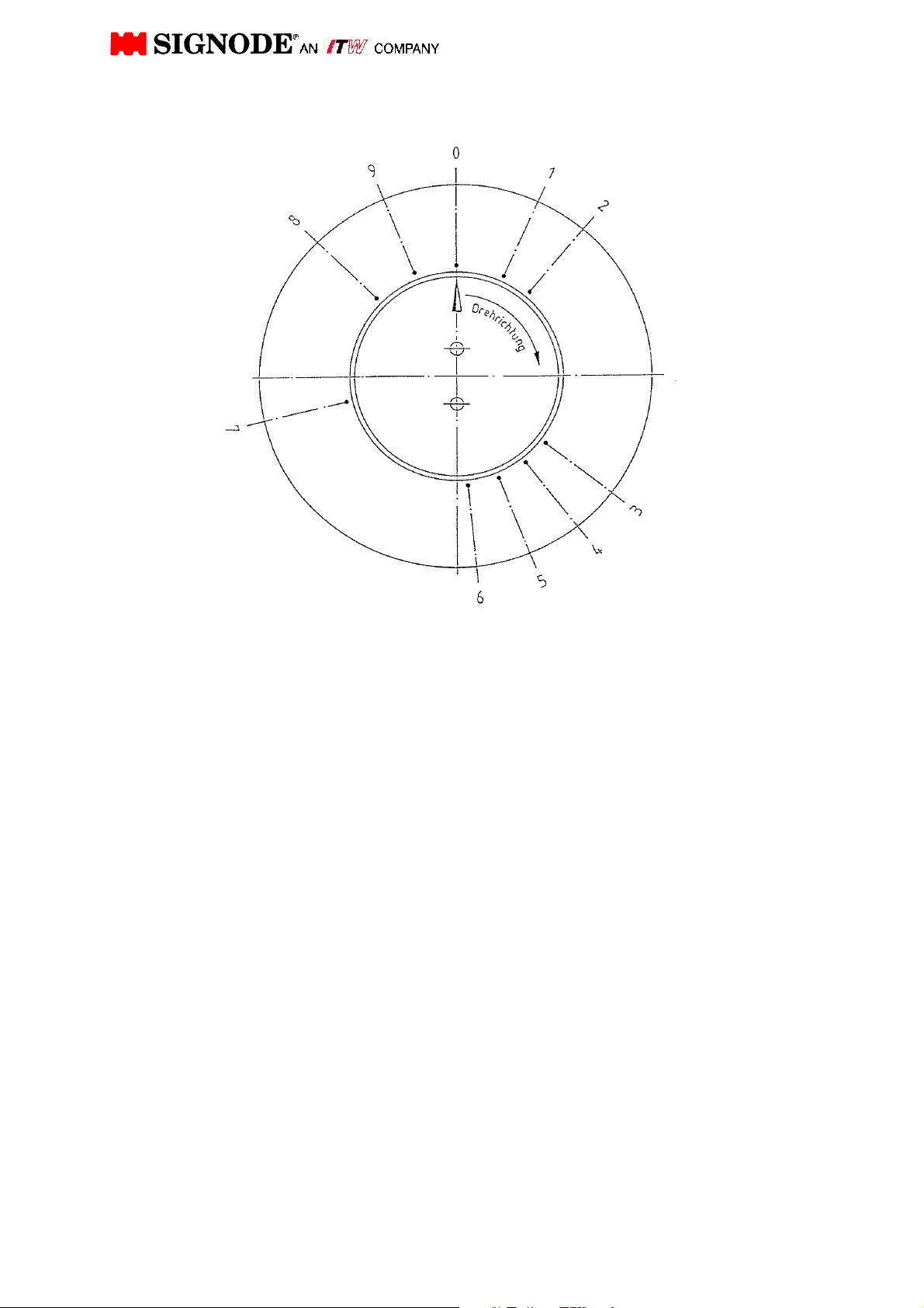
TENSION- AND SEALING PROCEDURE
0. Home position proximity switch B104 "shutter close" activated. Shutter closed.
1. Tip of strap is clamped. Proximity switch B106 "max. strap tension reached" will
be activated for the first time.
2. Proximity switch B105 "Pre- tension reached" will be free Switching into tension
slow speed.
3. Strap will be tensioned. Proximity switch B106 "max. strap tension reached" will
be de-activated again.
4. Maximal strap tension reached, cam follower is on highest point of cam. The
spring package is pressed together to its maximum for maximum pre-set strap
tension. Starting strap end clamped. Proximity switch B106 strap tension
reached will be occupied for the second time. Strap drive brake Y36 will be
connected.
5. Loop grip presses firmly both straps. Tip of strap and strap end clamped.
Proximity switch B105 "Pre-tension reached" will be activated again strap
slacken for cut off at no load starts.
6. Weld motor starts and strap will be cut. Proximity switch B105 "pre-tension
reached" will be free again.
7. Cool off joint. Pressing together both straps at camshaft strap. Proximity switch
B105 "Pre-tension" will be activated for the second time.
8. Vibrator, loop grip and gripper in home position. Proximity switch B104 "Shutter
close" will be free. Shutter starts opening.
9. Proximity switch B103 "Shutter open" is occupied and proximity switch B105
"pre-tension reached" will be free again. Shutter fully opened.
11
Page 26

4.2 COMMENTS TO THE PLANETARY GEAR DRIVE (Strap Drive)
The planetary gear drive on the strap drive has the following major function:
1. It takes over the strap feeding in feeding direction. The feed wheel ring is driven
via the solid shaft, drwg. 464626, pos. 2, page 47 and the planetary gears, pos.
10. The planetary gear shaft (hollow shaft) pos. 1 will be held in position by the
operative camshaft brake via the gear pos. 9.
2. It takes over the strap feed in take-up direction (tension direction). The feed
wheel ring is driven via the solid shaft drwg. 464626, pos. 2, page 47 and the
planetary gears pos. 10. Because the drive motor changes direction of rotation,
the strap feed also feeds in tension direction. When the max. strap tension has
been reached the feed wheel will stop. Hereby the planetary gear shaft (hollow
shaft) pos. 1 will be driven via the planetary gears pos. 10. The camshaft will be
driven by the gear pos. 9 via the intermediate shaft and the bevel gears.
12
Page 27

5. PREVENTIVE MAINTENANCE
Daily:
- Clean feed wheel and chain by using an air pistol.
- Shutter must be open to clean sealing mechanism, remove remaining weld scrap.
- Check whether strap limit switch works free of trouble and the strap tail is clamped.
(see section 7.2.)
Weekly:
- Check strap transportation, disconnect chain, check bearing and chain links, check feed
wheel ring if necessary exchange.
- Check strap guide wedge.
Clean switch actuator with air pistol. Check strap gates for easy movement.
- Check shutter for easy movement and apply oil to guide ways of rails if necessary.
Monthly:
- Grease the guide shaft
(see drwg. 464631, pos. 106, page 33).
- Remove and clean gripper complete, vibrator support and loop grip and apply with creep
oil (light oil).
- Apply grease to the vibrator guide way – the guide way will be lubricated with a high
temperature grease, (see drwg. 464655, pos. 20, 25, page 39).
- Needle bearing eccentric arm - eccentric shaft will be lubricated with a high temperature
grease, (see drwg. 464655 pos. 21, page 39)
- Grease bolt for eccentric arm (connection between vibrator and eccentric lever,
(see drwg. 464655, pos. 27).
- Grease the cam follower roller and check the cam follower roller for proper
rotation. Apply grease on both sides of lever - cam follower roller will be lubricated
with MOLYKOTE LONGTERM 2 PLUS, (see drwg. 464631, pos. 63, 64, 65, page 33).
- Check wear parts according to the enclosed recommended spare parts list and replace
parts if necessary.
Annually:
- Check all electrical connections and retighten any which appear to be loose.
- Check the weld motor brushes and inspect the motor armature for wear.
- Grease the needle bearing pos. 18 of strap drive (see drwg. 464626 page 47)
- Check the Belleville washer inside the gripper, loop gripper and vibrator support and replace
washers if necessary (see page 39 pos 75, Page 39a and b).
ATTENTION:
After a period of time or after exchange of wear parts check welded joints of strap samples.
Readjustments might be necessary, e.g. pressure of plungers or changes of welding time
(see section "Head Adjustments" point 7.1 and 7.4)
13
Page 28

6.0 PARTS REMOVAL AND REPLACEMENT
6.1 To remove the cam levers and lever for shutter
(see drwg. 464631, pos. 63, 64, 65, Page 33)
- Remove release pin (see drwg. 464631, pos. 58, page 33) and swing strap guide wedge
inclusive chain (see drwg. 464631, pos. 10, page 33) backwards. Also swing out the stop
device.
- Remove weld motor (see drwg. 464631, pos. 83, page 33) Attention - toothed belt!
- Push the grippers a bit forward, using a C-clamp to take the load off the cam levers.
- Remove socket head cap screws (see drwg. 464631, pos.35, page 33) and pull on lever
shaft (see drwg. 464631, pos. 33, Page 33).
- Remove lever shaft.
- Remove cam levers.
6.2 To remove loop grip "strap end"
(see drwg. 464655, pos. 7, Page 39)
- Remove spring retainer (see drwg. 464655, pos. 5, page 39) and the 2 PCs. pressure
springs with the guide pins.
- Open shutter (see drwg. 464655, pos. 1, page 39).
- Remove pressure pad for shutter (see drwg. 464655, pos.13, page 39)
- Remove socket head cap screw (see drwg. 464655, pos. 35, page 39).
- Pull out complete gripper.
6.3 To remove vibrator
(see drwg. 464655, pos. 25, page 39)
- Remove spring retainer (see drwg. 464655, pos. 5, page 39) and 2 pcs. pressure springs
with guide pins.
- Open shutter (see drwg. 464655, pos. 1, page 39).
- Remove pressure pad for shutter (see drwg. 464655,pos. 13, page 39).
- Remove socket head cap screw (see drwg. 464655, pos. 35, page 39).
- Remove connection bolt from vibrator and eccentric arm by removing the pin keeper (see
drwg. 464655, pos. 51).
- Pull out vibrator inclusive vibrator support.
Note: Cutter blade and vibrator bolt are loose and may fall down to the floor!
- Remove cutter blade and push out vibrator bolt (see drwg. 464655, pos. 24, page 39).
- Remove vibrator. Note, do not lose the 4 pcs. INA flat cage needle rollers, they must be
replaced again correctly (see drwg. 464655, pos.20, page 39).
Before you start with service please disconnect the chain. Remove
release pin (see drwg. 464631, pos. 58) and swing strap guide
wedge inclusive chain (see drwg. 464631, pos. 10, page 33)
backwards. Also please swing out the stop device by pull off the
catch pin 64643 Pos. 14 + 15, page 60)
14
Page 29

6.4 To remove gripper "tip of strap"
(see drwg. 464655, pos. 8, page 39)
- Dismantle gripper as described under point 6.2 and 6.3.
- Note, remove first vibrator incl. vibrator support before dismantling the gripper.
6.5 To remove clutch Y37 from transmission
(see drwg. 100.36, pos. 41, page 43)
- Remove 2 pcs. socket head cap screw and take off belt guard
(see drwg. 464631, pos. 55 - 57, page 33).
- Remove countersunk screw and washer (see drwg. 100.36, pos. 46, 20, page 43).
- Pull off magnet part of clutch.
- Remove socket head cap screws (see drwg. 100.46, pos. 33, page 43) and slide off the
armature of the shaft (see drwg. 100.36, pos.50, page 39).
- Install new clutch.
ATTENTION:
When installing the clutch make sure that the armature and the rotor are free of grease or oil
and that the gap between them is 0.2 mm (The gap can be set by using a calibrated disc), (see
drwg. 100.36, pos. 42, page 43).
6.6 To remove the transmission
(see drwg. 464631, pos. 8, page 33)
- Remove pulley guards (see drwg. 464631, pos. 39, 55, page 33).
- Loose socket head cap screw (see drwg. 464631, pos. 19, page 33) to slacken toothed
V-belt (see drwg. 464631, pos. 61, page 33)
- Remove timing belt.
- Remove socket head cap screw (see drwg. 100.36, pos. 63, page 43) and take off the
transmission. In order to reduce down time, we recommend the purchase of a
transmission for quick exchange.
6.7 To remove the feedwheel ring
(see drwg. 464626, pos. 6, page 47)
- Remove release pin (see drwg. 464631, pos. 58, page 33) and swing back strap guide
wedge (see drwg. 464631, pos. 10, page 33) with strap guide chain.
- Remove weld motor (see drwg. 464631, pos. 83, page 33).
- Remove lower fitting bolt of seal mechanism (see drwg. 464655, pos. 55, page 39).
By removing the weld motor, the hexagonal nut of the fitting bolt is easily accessible.
- Swing guide wedge (see drwg. 464655, pos. 60, page 47) forward.
- Remove 6 pcs. socket head cap screws (see drwg. 464626, pos. 34, page 47).
- Insert 2 pcs. socket head cap screws into plan gear cover (see drwg. 464626, pos. 3,
page 47) to pull off cover.
- Take off feed wheel ring.
15
Page 30

6.8 To remove cams from camshaft display
(see drwg. 464613, page 33)
- Remove release pin (see drwg. 464631, pos. 58, page 33).and swing back strap guide
wedge with strap guide chain (see drwg. 464631, pos. 10, page 33). Also swing out the
stop device.
- Remove the spring retainer (see drwg. 464655, pos. 5, page 39) and the 2 pcs. pressure
springs with guide pins.
- Open shutter . (see drwg. 464655, pos. 1, page 39)
- Remove pressure pad for shutter, (see drwg. 464655, pos. 13, page 39)
- Push gripper forward using a C-clamp to take the load off the cam levers.
- Turn back adjustment screws from levers. Adjustment screws should not put any
pressure on the cross bars of grippers (see drwg. 464631, pos. 94, page 33).
- Rotate camshaft into position 7.
- Remove socket head cap screws from camshaft flange.
- Use long socket head cap screws and insert them into thread of camshaft flange, pull off
camshaft flange.
Note: Take care that the cams have no contact with the levers and the proximity switches.
- Remove camshaft.
- Remove countersunk screw and disc (see drwg. 464613, pos. 7 and 17, page 33) and
remove bevel gear and ball bearing.
- Remove the cams and exchange cams if necessary.
6.9 To remove belleville washers from spring assembly
(see drwg. 100.007, pos. 11, page 58)
- Remove release pin (see drwg. 464631, pos.58, page 33) and swing back strap guide
wedge with strap guide chain (see drwg. 464631, pos. 10, page 33). Also swing out the
stop device.
- Remove sleeve (see drwg. no. 100.007,pos. 2, page 58) from guide shaft (see drwg.
100.007,pos. 1, page 58).
- Remove adjustment nut (see drwg. no. 100.007, pos. 4, page 58).
- Exchange belleville washers.
16
Page 31
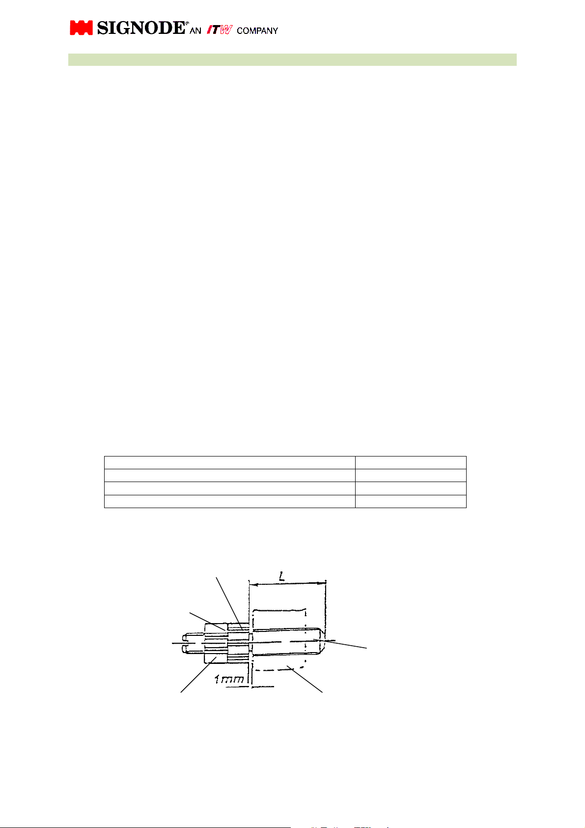
7. HEAD ADJUSTMENTS
7.0 Re-adjustment of gripper, loop grip and vibrator are necessary if:
1. Cam levers are replaced.
2. Adjustment screws are replaced.
3. Gripper, loop grip or vibrator support are replaced.
Re-adjustment must be carried out as follows:
To begin with, set the adjustment screw for each setting according to the table "Normal setting
of the adjustment screw length AK200". Then fix the grooved collar in a vice (with soft pinch
bars) and tighten the lock nut.
Turn the adjustment screw into the cam lever until a gap of 1 mm remains between the cam
lever and the grooved collar. In case the gripping force is insufficient for welding joint, clamping
tip of strap or clamping strap end, re-adjustments as described in sections 7.1 till 7.3 should be
made.
Whenever re-adjustments have been made, it is necessary to maintain a remaining gap of 0.5
mm between the cam lever and the grooved collar after the proper pressure has been set, so
that the pressure still can be increased.
In order to accomplish this, the screw length "L" shown in the table may have to be increased.
Adjustment of screw length AK200
Adjustment screw for „plunger 1“ strap end clamped length approx. 30 mm
Adjustment screw for „plunger 2“ Vibrator length approx. 32 mm
Adjustment screw for „Gripper tip of strap“ length approx. 30 mm
Notched disc
Lock washer
Adjustment screw
Counter nut Lever
17
Page 32

7.1 Adjustment of pressure for straps to be joint (vibrator)
(see drwg. 464655, pos. 9, 25, page 39)
- Pre-feed strap until tip of strap exits the head
- Rotate camshaft into position 7 (now only one strap will be clamped by the vibrator
against the shutter).
- Tighten the adjustment screw always by 1 raster (1 raster equals increase of 0.125 mm)
until the vibrator is clamping the strap against the shutter. The strap is being clamped
when increased resistance is noticeable.
- Rotate camshaft into position 9 and remove cut off strap from head pressure marks from
the vibrator and the gripper pad of the shutter must be noticeable on the strap end
- Rotate camshaft into home position 0.
7.2 Gripper adjustment for clamping strap tip
(see drwg. 464655, pos. 8, page 39)
- Rotate camshaft into position 7 (without strap in sealing mechanism).
- Tighten the adjustment screw always by 1 raster until gripper rests on limit stop edge of
the pressure pad - shutter, (see drwg. 464655, pos. 13, page 39).
Note: If the clamping force for the strap tip is set too low, the strap slips in
the clamping zone.
7.3 Loop grip adjustment for clamping strap end
(see drwg. 464655, pos. 7, page 39)
- Pre-feed strap until tip of strap exits the head.
- Rotate camshaft into position 7.
(Now only one strap will be clamped by the loop grip against the shutter).
- Tighten the adjustment screw always by 1 raster until the gripper is clamping the strap.
The strap is being clamped when increased resistance is noticeable.
- Rotate camshaft into position 9 and remove cut off strap from head. Pressure marks from
the gripper pad of the gripper must be noticeable on the strap end.
- Rotate camshaft into home position 0.
To point 7.0 through 7.3:
During our training period of your operator and maintenance personnel, we point their attention
to results which may occur to the machine due to incorrect adjustments.
Because of the high resistance from the tension cam it is not possible
to turn the camshaft by hand.
If it necessary to turn the camshaft by hand, please disconnected first
the strap guide chain.
Remove the release pin (see drawing 0464631 Pos. 58, page 33) and
swing strap guide wedge inclusive chain (see drawing 0464631 Pos.
10, page 33) backwards.
Also please swing out the stop device by pull off the catch pin (see
drawing 0464643 Pos. 14 + 15, page 60)
18
Page 33

7.4 Adjustment of welding joint
The intensity of the welding joint depends on the set time in the program sequence.
To receive best results of joint strength, the welding time and cool off time will be set according
to the strap quality at the acceptance run of the head.
If strap quality changed, welding time and probably the cool off time must be changed by
qualified personnel only.
After a period of time or after exchange of wear parts check welded joints of strap samples. Resetting of welding time might be necessary.
Additional time values stored in the program sequence for head function control must be
changed only by a Signode service engineer.
7.5 Adjustment of strap tension
The spring assembly (see drwg. 464631, pos. 9, page 33) permits the variation or adjustment of
the strap tension.
To increased strap tension, turn the threaded collar (see drwg. 100.07, pos. 4, page 58) with a 6
mm round pin against the disc washers. At the same time hold the socket head cap screw, (see
drwg. 100.07, pos. 13, page 58), to prevent the guide shaft (see drwg. 100.07, pos. 1, page 58)
from turning.
7.6 Adjustment of the roller chain
The proper chain tension is set at the factory for a particular strap thickness. If adjustments are
necessary, please pay attention to the following:
a) Compression spring "Pre-tension reached" ("Changing into slow tension") according to fig.
100.07, page 58. Adjustment of spring, stroke with strap being inserted must be about 5 mm
- 6 mm.
b) Basic position. - Additional compression spring for pre-tension of chain must be adjusted
without strap so that between spring and limit stop of strap guide a clearance of 1 mm
exists, see fig. 100.15, page 60.
If slip markings on strap occur (wear of feed wheel ring) the compression spring must be readjusted to more tension until slipping marks disappear. Set chain pressure as high as
necessary but, so that the strap will not be deformed. After exchange of a feed wheel ring,
the basic setting must be obtained as described above, see fig. 100.15, page 60.
7.7 Adjustment of the proximity switches in the head
All proximity switches are set by the manufacturer and marked with a colored seal. They need
no adjustment. If re-adjustments are necessary, they should be done by qualified personnel
only.
19
Page 34
8. TROUBLE SHOOTING
8.00 OPERATIONAL DIFFICULTIES DURING STRAP FEEDING
S Y M P T O M C A U S E R E M E D Y
8.01 Incomplete or improper strap feed. Strap feed disturbance into the head. Inspect dispenser, accumulator and pulleys
etc.
Strap hits strap guide. Check strap guide.
8.02 More than one layer of strap is fed into the
chute and stops after time delay setting.
8.03 The strap drive and the camshaft do not
move while the motor runs.
20
8.04 After completion of a strapping cycle the
strap tip hits the cutter blade when re-entering.
Spring in pressure pad (in pos. 8, drwg.
8.05 No strap feed. Strap switch B102 stays activated. Strap
8.06 Too much strap overlap. strap feeds too far. Time has been set too long. Time setting must be changed by
Malfunction of strap stop limit switch B102. Inspect limit switch, replace or adjust as
required.
The small clutch Y37, 15 Nm at transmission
100.36 page 43 is not activated.
The vibrator support jams. Remove and clean, see section 6.3 of the
464655 page 39b) jams or is missing.
switch B183 is not activated.
Inspect fuse, fast switching device and cable
terminals of transmission.
manual.
Free pressure pad or insert spring.
Check switch actuator and actuator lever.
Ejector gate jams (clean). Check function of
proximity switch.
reprogramming the CPU. (Please inform
service department)
20
Page 35
8.10 OPERATIONAL DIFFICULTIES DURING STRAP TAKE-UP
S Y M P T O M C A U S E R E M E D Y
8.11 Strap is fed backwards out of the strap drive,
while the camshaft stops between points 1 and 2.
Gripper support is set too tight. Reset, see section 7.0/7.2 of the manual.
Strap in feed disturbance at strap guide
Gripper support is jammed. Remove and clean: see section 6.4 of the
8.12 Strap drive at take-up shifts too soon into low
21
gearing.
Pre-tension spring for strap tension set too
8.13 The head pulls the strap too hard down onto
the package and the camshaft does not stop shortly
before point 4.
Large clutch Y22 in transmission is defect. Exchange transmission, see section 6.6 of the
Fast switching device for clutchs is defect. Replace fast switching devices.
8.14 Strap drive and the camshaft do not move
while the motor runs.
Tip of strap did not enter its end position. Timing must be changed by reprogramming
the CPU. (Please inform service department)
Straighten chute gates or increase the bell
wedge.
Strap hits shutter.
Gripper support is set too tight. Reset, see section 7.0/7.2 of the manual.
soft.
Pre-tension spring for strap tension set too
high.
One or both clutches are not activated Y22,
Y37.
mouth.
manual.
Readjust pre-tension spring.
Readjust pre-tension spring.
manual, and replace exchange-transmission.
Inspect fuse, fast switching device and cable
terminals of transmission.
21
Page 36
8.20 OPERATIONAL DIFFICULTIES DURING STRAP TENSION
S Y M P T O M C A U S E R E M E D Y
8.21 The strap drive does not move, there is a
squeaking noise and the camshaft stops shortly
before point 4.
Strap tension is set too high. Adjust strap tension, see section 7.5 of the
Guide shaft for belleville washers gets stuck.
8.22 The feed wheel rotates in take-up direction
but does not tension the strap, while the camshaft
stops shortly before point 4.
22
Readjust pre-tension spring, adjustment too
8.23 During take-up (strap tension) the strap tip is
being pulled out of the head while the camshaft
stops shortly before point 4.
The teeth of the clamping pad are worn.
8.24 The strap drive and the camshaft do not
move while the motor runs.
8.25 Strap tension looses on package after max.
strap tension at camshaft point 5.
Large clutch Y22 in transmission is worn out. Exchange transmission, see section 6.6 of the
manual.
manual.
Grease or oil guide shaft. Check guide shaft
The feed wheel ring slips. Clean feed wheel ring or replace, see section
Gripper support is set too tight. Readjust contact pressure, see section 7.0
One or both clutches are not activated, Y22,
Y37.
Loop grip has not sufficient contact pressure
(slipping marks).
for wear.
6.7 of the manual. If feed wheel ring exchange
necessary, reduce strap tension adjustment.
low.
and 7.2.
Replace, see section 6.4 of the manual.
Inspect fuse, fast switching device and cable
terminals of transmission. Check slip disc of
clutches.
Readjust loop grip, see section 7.3.
22
Page 37
8.30 OPERATIONAL DIFFICULTIES DURING "SEALING AND CUT-OFF"
S Y M P T O M C A U S E R E M E D Y
8.31 The strap is taken up slowly while the
camshaft stops between points 5 and 6.
8.32 Camshaft does not reach holding point 7. Proximity switch B105 “Pre-tension reached”
8.33 The camshaft does not stop at holding point
9.
23
8.34 The strap drive and the camshaft do not
move while the motor runs.
8.35 At the backside of the joint the strap is
damaged or deformed.
Gates on strap guide wedge get stuck. Straighten gates.
Brake Y38 is not activated. Check the switch B106 "max. strap tension".
Check connection of brake plug.
Check proximity switch.
defect
Proximity switch B103 "Shutter open" defect or
switch position not reached.
Proximity switch B105 “Pre-tension reached”
defect
One or both clutches are not activated, Y22
,Y37.
Shutter does not fully open. The proximity switch B103 "Shutter open" will
Check proximity switch. Align sensor actuator.
Inspect fuse, fast switching device and cable
terminals of transmission.
be actuated too early.
23
Page 38
S Y M P T O M C A U S E R E M E D Y
8.36 No exact weld joint. Insufficient vibrator contact pressure. Readjust contact pressure, see section
7.0/7.1.
Eccenter drive for vibrator defect. Check motor M28 connection terminal.
Check brushes for weld motor.M28
Check bolt for eccentric arm (see drwg.
464655, pos. 27, page 39) for wear.
Check needle bearing (see drwg. 464655,
pos. 21, page 39) on eccenter shaft
Open shutter and check easy movement of
24
8.37 Strap is not being cut off correctly. Tolerance between cutter blade and gripper too
large.
Insert spacer between cutter blade and
vibrator drive.
Reduce tolerance of gripper by readjusting
setting screws (see drwg. 464655, pos. 47,
48, Page 39).
ATTENTION: Plungers (grippers) must move
freely!
vibrator support (see drwg. 464655, pos. 22,
23, page 39).
ATTENTION: Plungers (gripper) must move
freely!
24
Page 39
Pos. in
Sub
-
Ass'y.
Pos. in
Sub
-
Ass'y.
9. RECOMMENDED SPARE PARTS LIST AK200-HDX-32 MM
Part-no: 0464690
Sub-assembly seal mechanism
Pos. Qty. Description Part N°.
1 1 Shutter complete
2 1 Loop grip, complete
3 1 Gripper, complete
4 1 Vibrator
5 2 Vibrator bolt
6 4 INA-Flat cage needle roll FF 2010
7 1 Eccenter arm bolt
8 1 Needle bearing NK 12/16
9 2 Oil-seal
10 1 Cutter blade
11 0 Spacer
12 3 Lock ring 12 extern DIN 471
13 1 Pin keeper
14 1 Gripper pad ( for Shutter )
15 1 Lock ring 4,0 DIN 6799
16 2 Pressure spring KM3235 x 120 lg
17 4 Pressure spring D-231
18 2 Pressure spring D-230 A
19 4 Pressure spring D-063 F
20 1 Spring D-166
21 1
22 1
23 1 Schnorr safety disk H1235/5
ASSEMBLY AK200-HDX HEAD
Gripper plate HDX
19 mm / 25 mm / 32 mm
SHC Head cap screw shallow head
M5x16 / DIN 7984-
464660 1
464676 7
464669 8
464677 25
464233 24
464228 20
464371 27
464373 21
464374 78
464687 22
464232 23
0WT2810 52
464370 51
464659 63
464661 64
464686 31
461428 33
461429 34
464239 67 in Pos. 7
460320 59
464675 68 in Pos. 7
464406 76
464398 77
Pos. Qty. Description Part N°.
24 1 Pressure spring D-050 461754 102
25 1 Pressure spring D-279 461430 108
26 1 Pressure spring D-337 461420 105
27 1 Feed wheel ring 464633 103
28 1 Timing belt HTD 318-3M-9 464253 69
29 1 Timing belt HTD-535-5M-15 462915 61
30 1 Timing belt HTD-960-8M-30 462845 60
31 1
32 1
33 1 Motor pulley 40 z 280413 70
34 1 Pulley 28 z 280412 71
35 1 set Brushes for weld motor EM 94-50, 230V 464382 83a
Proximity switch NBB-2-V3-E2-V5
Proximity switch IFM IN 5129
25
461764 77 - 80
464400 76, 81
Page 40
Pos. in
Sub
-
Ass'y.
Pos. in
Sub
-
Ass'y.
9. RECOMMENDED SPARE PARTS LIST AK200-HDX-25 MM
Part-no: 0464691
Sub-assembly seal mechanism
Pos. Qty. Description Part N°.
1 1 Shutter complete
2 1 Loop grip, complete
3 1 Gripper, complete
4 1 Vibrator
5 2 Vibrator bolt
6 4 INA-Flat cage needle roll FF 2010
7 1 Eccenter arm bolt
8 1 Needle bearing NK 12/16
9 2 Oil-seal
10 1 Cutter blade
11 0 Spacer
12 3 Lock ring 12 extern DIN 471
13 1 Pin keeper
14 1 Gripper pad ( for Shutter )
15 1 Lock ring 4,0 DIN 6799
16 2 Pressure spring KM3235 x 120 lg
17 4 Pressure spring D-231
18 2 Pressure spring D-230 A
19 4 Pressure spring D-063 F
20 1 Spring D-166
21 1
22 1
23 1 Schnorr safety disk H1235/5
ASSEMBLY AK200-HDX HEAD
Gripper plate HDX
19 mm / 25 mm / 32 mm
SHC Head cap screw shallow head
M5x16 / DIN 7984-
464660 1
464676 7
464669 8
464677 25
464233 24
464228 20
464371 27
464373 21
464374 78
464687 22
464232 23
0WT2810 52
464370 51
464659 63
464661 64
464686 31
461428 33
461429 34
464239 67 in Pos. 7
460320 59
464675 68 in Pos. 7
464406 76
464398 77
Pos. Qty. Description Part N°.
24 1 Pressure spring D-050 461754 102
25 1 Pressure spring D-279 461430 108
26 1 Pressure spring D-337 461420 105
27 1 Feed wheel ring 464635 103
28 1 Timing belt HTD 318-3M-9 464253 69
29 1 Timing belt HTD-535-5M-15 462915 61
30 1 Timing belt HTD-960-8M-30 462845 60
31 1
32 1
33 1 Motor pulley 40 z 280413 70
34 1 Pulley 28 z 280412 71
35 1 set Brushes for weld motor EM 94-50, 230V 464382 83a
Proximity switch
Proximity switch
461764 77 - 80
464400 76, 81
26
Page 41
Pos. in
Sub
-
Ass'y.
Pos. in
Sub
-
Ass'y.
9. Recommended spare parts list AK200-HDX-19 mm
Part-no: 0464692
Sub-assembly seal mechanism
Pos. Qty. Description Part N°.
1 1 Shutter complete
2 1 Loop grip, complete
3 1 Gripper, complete
4 1 Vibrator
5 2 Vibrator bolt
6 4 INA-Flat cage needle roll FF 2010
7 1 Eccenter arm bolt
8 1 Needle bearing NK 12/16
9 2 Oil-seal
10 1 Cutter blade
11 0 Spacer
12 3 Lock ring 12 extern DIN 471
13 1 Pin keeper
14 1 Gripper pad ( for Shutter )
15 1 Lock ring 4,0 DIN 6799
16 2 Pressure spring KM3235 x 120 lg
17 4 Pressure spring D-231
18 2 Pressure spring D-230 A
19 4 Pressure spring D-063 F
20 1 Spring D-166
21 1
22 1
23 1 Schnorr safety disk H1235/5
ASSEMBLY AK200-HDX HEAD
Gripper plate HDX
19 mm / 25 mm / 32 mm
SHC Head cap screw shallow head
M5x16 / DIN 7984-
464660 1
464676 7
464669 8
464677 25
464233 24
464228 20
464371 27
464373 21
464374 78
464687 22
464232 23
0WT2810 52
464370 51
464659 63
464661 64
464686 31
461428 33
461429 34
464239 67 in Pos. 7
460320 59
464675 68 in Pos. 7
464406 76
464398 77
Pos. Qty. Description Part N°.
24 1 Pressure spring D-050 461754 102
25 1 Pressure spring D-279 461430 108
26 1 Pressure spring D-337 461420 105
27 1 Feed wheel ring 464475 103
28 1 Timing belt HTD 318-3M-9 464253 69
29 1 Timing belt HTD-535-5M-15 462915 61
30 1 Timing belt HTD-960-8M-30 462845 60
31 1
32 1
33 1 Motor pulley 40 z 280413 70
34 1 Pulley 28 z 280412 71
35 1 set Brushes for weld motor EM 94-50, 230V 464382 83a
Proximity switch NBB-2-V3-E2-V5
Proximity switch IFM IN 5129
27
461764 77 - 80
464400 76, 81
Page 42
Pos. in
Sub
-
Ass'y.
Pos. in
Sub
-
Ass'y.
Pos. in
Sub
-
Ass'y.
Pos. in
Sub
-
Ass'y.
10. REMOTE SPARE PARTS LIST AK200-HDX-32 mm
Part-no: 464693
Assembly Head
Pos. Qty. Description Part N°.
1 1 Cam follower KR 19 PP 464289 86
2 5 DU-Bushing 2515 DU 463382 87
3 5 Roller version 1 463377 88
4 5 Pin version 1 463378 89
5 10 Bolt lock 461097 90
6 10 Countersunk screw M4x6 DIN 7991 462105 91
7 3 Snapper M8 462033 92
8 6 Grooved collar 462299 93
9 3 Adjustment screw 462298 94
10 3 Washer 462428 95
11 1 Head motor 230/400 V, 3Ph, 50 Hz 461059 82
12 1 Timing belt pulley 462914 31
13 1 Weld-Motor EM 94-50, 230V 50/60Hz 464381 83
14 1 Transmission complete 462953 8
15 1 "Camshaft Brake " 462840 7
16 1 Strap guide chain complete 464623 17
17 1 Gate, right vers. 32 464638 96
18 1 Gate, left vers. 32 464639 97
19 2 Spring retainer 072400 98
20 2 Spring retainer 040460 99
21 4 Gate spring 072432 100
22 1 Switch lever 462133 101
23 42 Belleville washer 462995 104
24 1 Guide shaft 460648 106
25 1 Pressure spring D-313 Q 462484 107
26 1 Segment version HDX-32 464648 109
Sub-assembly Sealing Mechanism
Pos. Qty. Description Part N°.
27 1 Eccentric shaft 464367 28
28 1 Eccentric arm 464368 26
29 2 Ball bearing W 201 PP 464372 49
30 2 Lock ring, 32 DIN 472 0WT2922
31 2 Lock ring, 19 DIN 472 0WT2913
Sub-assembly brake
Pos. Qty. Description Part N°.
32 2 Membrane (spring) 462780 22
33 1 Plug 462908 23
Sub-assembly camshaft
Pos. Qty. Description Part N°.
34 2 Bevel gear 462963 13 (6)
35 1 Free wheel 462538 23
36 1 Shaft 462964 1
28
50
53
Page 43
Pos. in
Sub
-
Ass'y.
Pos. in
Sub
-
Ass'y.
Pos. in
Sub
-
Ass'y.
Pos. in
Sub
-
Ass'y.
10. REMOTE SPARE PARTS LIST AK200- HDX-25
Part-no: 464694
Assembly Head
Pos. Qty. Description Part N°.
1 1 Cam follower KR 19 PP 464289 86
2 5 DU-Bushing 2515 DU 463382 87
3 5 Roller version 1 463377 88
4 5 Pin version 1 463378 89
5 10 Bolt lock 461097 90
6 10 Countersunk screw M4x6 DIN 7991 462105 91
7 3 Snapper M8 462033 92
8 6 Grooved collar 462299 93
9 3 Adjustment screw 462298 94
10 3 Washer 462428 95
11 1 Head motor 230/400 V, 3Ph, 50 Hz 461059 82
12 1 Timing belt pulley 462914 31
13 1 Weld-Motor EM 94-50, 230V 50/60 Hz 464381 83
14 1 Transmission complete 462953 8
15 1 "Camshaft Brake " 462840 7
16 1 Strap guide chain complete 464623 17
17 1 Gate, right vers. 25 464461 96
18 1 Gate, left vers. 25 464462 97
19 2 Spring retainer 072400 98
20 2 Spring retainer 040460 99
21 4 Gate spring 072432 100
22 1 Switch lever 462133 101
23 42 Belleville washer 462995 104
24 1 Guide shaft 460648 106
25 1 Pressure spring D-313 Q 462484 107
26 1 Segment version HDX 25 464649 109
Sub-assembly Sealing Mechanism
Pos. Qty. Description Part N°.
27 1 Eccentric shaft 464367 28
28 1 Eccentric arm 464368 26
29 2 Ball bearing W 201 PP 464372 49
30 2 Lock ring 32 DIN 472 0WT2922
31 2 Lock ring 19 DIN 472 0WT2913
Sub-assembly brake
Pos. Qty. Description Part N°.
32 2 Membrane (spring) 462780 22
33 1 Plug 462908 23
Sub-assembly camshaft
Pos. Qty. Description Part N°.
34 2 Bevel gear 462963 13 (6)
35 1 Free wheel 462538 23
36 1 Shaft 462964 1
29
50
53
Page 44
Pos. in
Sub
-
Ass'y.
Pos. in
Sub
-
Ass'y.
Pos. in
Sub
-
Ass'y.
Pos. in
Sub
-
Ass'y.
10. REMOTE SPARE PARTS LIST AK200- HDX-19
Part-no: 464695
Assembly Head
Pos. Qty. Description Part N°.
1 1 Cam follower KR 19 PP 464289 86
2 5 DU-Bushing 2515 DU 463382 87
3 5 Roller version 1 463377 88
4 5 Pin version 1 463378 89
5 10 Bolt lock 461097 90
6 10 Countersunk screw M4x6 DIN 7991 462105 91
7 3 Snapper M8 462033 92
8 6 Grooved collar 462299 93
9 3 Adjustment screw 462298 94
10 3 Washer 462428 95
11 1 Head motor 230/400 V, 3Ph, 50 Hz 461059 82
12 1 Timing belt pulley 462914 31
13 1 Weld-Motor EM 94-50, 230V 50/60 Hz 464381 83
14 1 Transmission complete 462953 8
15 1 "Camshaft Brake " 462840 7
16 1 Strap guide chain complete 464623 17
17 1 Gate, right vers. 19 464461 96
18 1 Gate, left vers. 19 464462 97
19 2 Spring retainer 072400 98
20 2 Spring retainer 040460 99
21 4 Gate spring 072432 100
22 1 Switch lever 462133 101
23 42 Belleville washer 462995 104
24 1 Guide shaft 460648 106
25 1 Pressure spring D-313 Q 462484 107
26 1 Segment version HDX 19 464649 109
Sub-assembly Sealing Mechanism
Pos. Qty. Description Part N°.
27 1 Eccentric shaft 464367 28
28 1 Eccentric arm 464368 26
29 2 Ball bearing W 201 PP 464372 49
30 2 Lock ring, 32 DIN 472 0WT2922
31 2 Lock ring, 19 DIN 472 0WT2913
Sub-assembly brake
Pos. Qty. Description Part N°.
32 2 Membrane (spring) 462780 22
33 1 Plug 462908 23
Sub-assembly camshaft
Pos. Qty. Description Part N°.
34 2 Bevel gear 462963 13 (6)
35 1 Free wheel 462538 23
36 1 Shaft 462964 1
30
50
53
Page 45
Pos. in
Sub
-
Ass'y.
Pos
.
Pos. in
Sub
-
Ass'y.
Pos
.
Pos. in
Sub
-
Ass'y.
CONVERSION KIT to AK200-HDX-32
Part-no: 464696
Pos Qty. Description Part N°.
1 1 Segment AK200-32 464648 109 Page 33
2 1 Strap guide wedge AK200-32 compl. 464682 60a Page 39
3 1 Strap guide wedge AK200-32 compl. 464636 10 Page 33
4 1 Guide AK200-32 464678 62 Page 39
5 2 Spacer 464683 15 Page 39
6 0 Side guide ring 7 Page 48
8 1 Feed wheel ring 464633 6 Page 48
CONVERSION KIT to AK200-HDX-25
Part-no: 464697
Qty. Description Part N°.
1 1 Segment AK200-25 464649 109 Page 33
2 1 Strap guide wedge AK200-25 compl. 464685 60a Page 39
3 1 Strap guide wedge AK200-25 compl. 464465 10 Page 33
4 1 Guide AK200-25 464452 62 Page 39
5 2 Spacer 464459 15 Page 39
6 0 Side guide ring 7 Page 48
8 1 Feed wheel ring 464635 6 Page 48
CONVERSION KIT to AK200-HDX-19
Part-no: 464698
Qty. Description Part N°.
1 1 Segment AK200-HDX-19 464650 109 Page 33
2 1 Strap guide wedge AK200- HDX-19 comp. 464516 60a Page 39
3 1 Strap guide wedge AK200- HDX-19 comp. 464310 10 Page 33
4 1 Guide AK200- HDX-19 464317 62 Page 39
5 2 Spacer 464221 15 Page 39
6 1 Side guide ring 464634 7 Page 48
8 1 Feed wheel ring 464475 6 Page 48
9 6 Thread pinM4x8 463449 35 Page 49
31
Page 46

Electrical Plans
11. SUB-ASSEMBLY DRAWINGS & PARTS LIST
Page
464631 vers. 32 mm
Strapping Head
464624 vers. 25 mm
464618 vers. 19 mm
464655 vers. 32 mm
Sealing Mechanism
464656 vers. 25 mm
464657 vers. 19 mm
Transmission - 15 - 100.36 43
Strap Drive 464626 47
Brake 100.14 50
Intermediate Shaft 464291 52
Camshaft 464505 54
33
39
"Camshaft Brake " 150.15 56
Spring Assembly 100.07 58
Insert Guide with Spring 464643 60
Strap Guide Wedge 464465 62
Air Blowing Device 464269 64
Installation 1 Plug Wiring 65
2 Plugs Wiring 66
32
Page 47
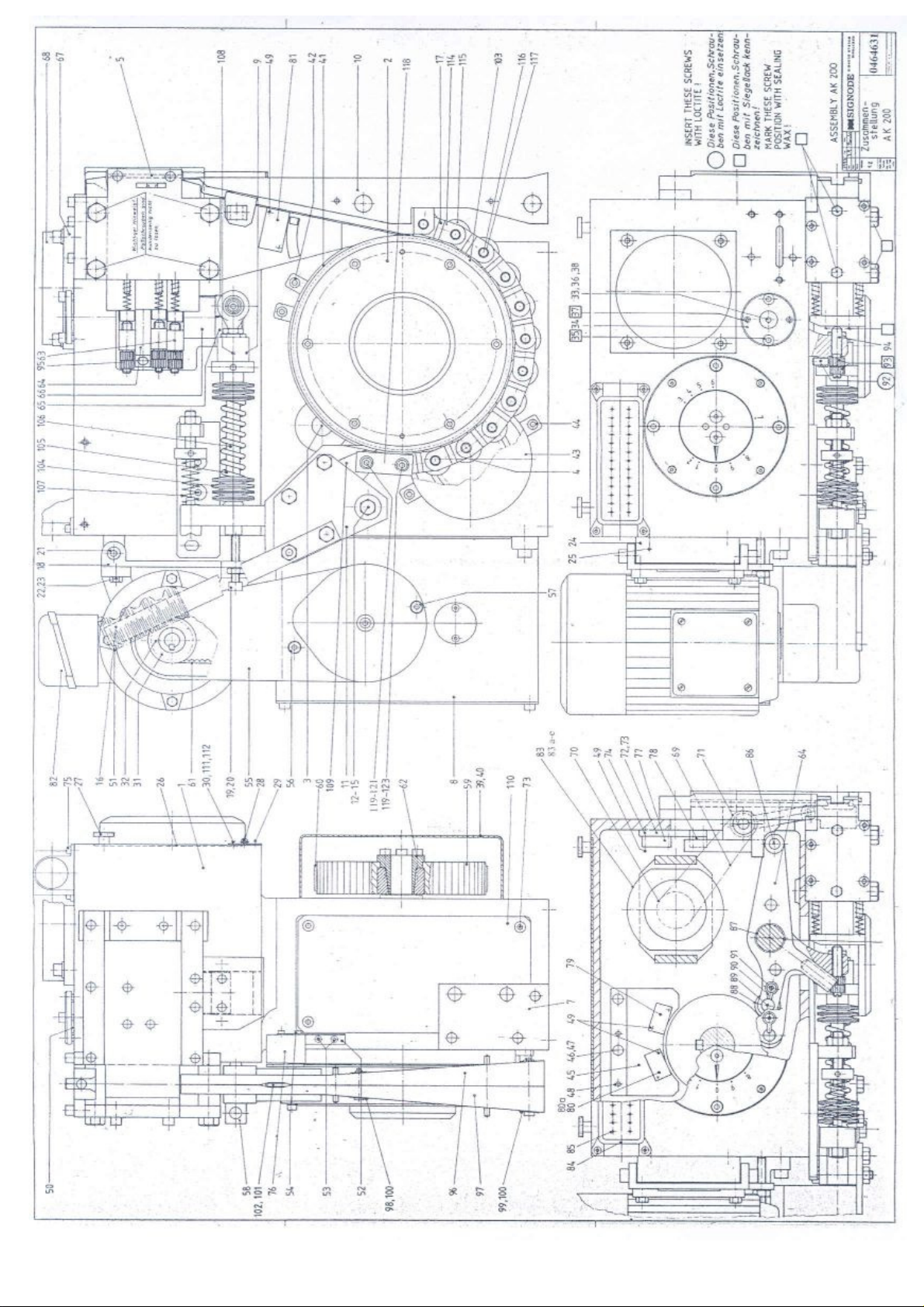
33
Page 48
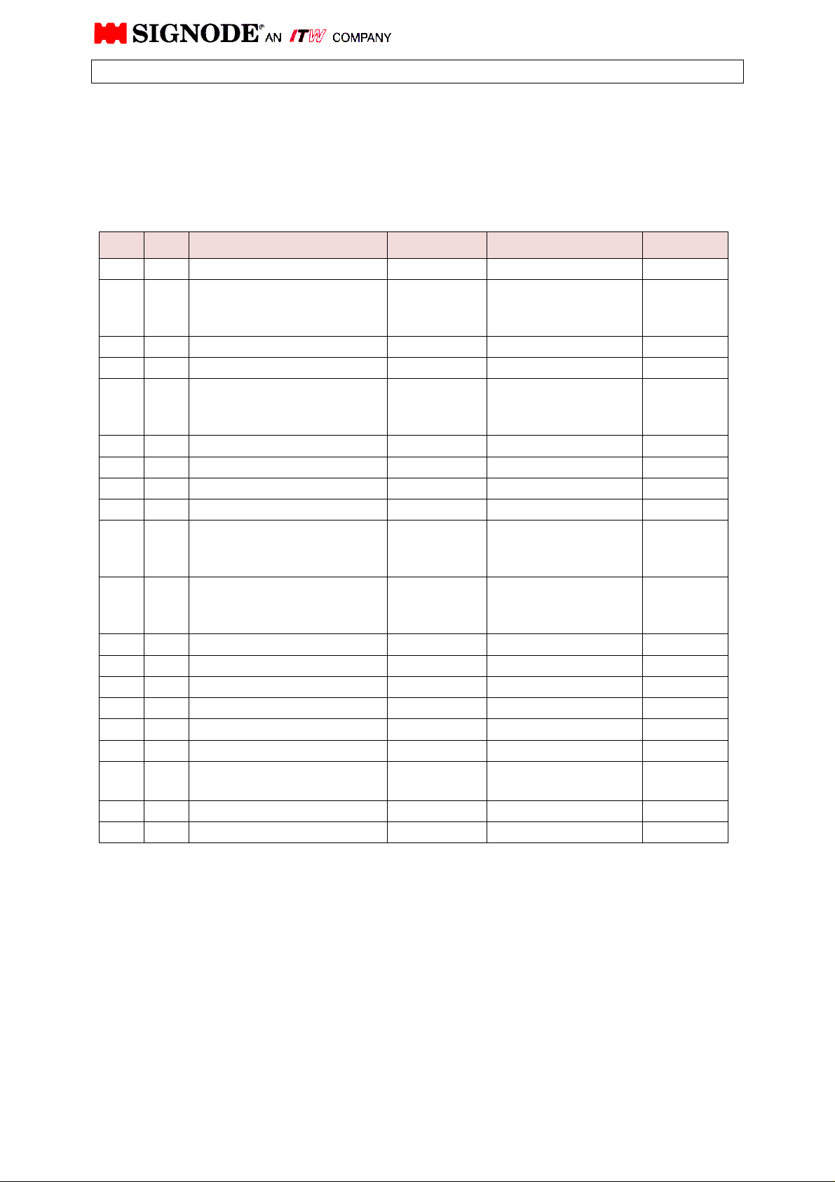
PARTS LIST
Description: Strapping head AK200-HDX
Drawing N°: 464631
Version/Part-No.: 32 mm strap size 464631
25 mm strap size 464624
19 mm
strap size
464618
Pos. Qty.
1 1 Housing 464600
2 1
3 1 Intermediate shaft, compl. 464291
4 1 Sub Assy. Brake 100.14 462459
5 1
6 1 Sub Assy. Camshaft Version 32 mm 464613
7 1 Sub Assy. Camshaft Brake 150.15 462840
8 1 Sub Assy. Transmission 100.36 462953
9 1 Sub Assy. Spring 100.07 461445
10 1 Strap guide wedge
11 1
12 1 Pin Version 32 mm 464654
13 1 Hex. screw M18x16 933 0WT0460
14 1 Washer 8,4 – 25,2 9021 462102
15 1 Thread pin M8x10 916 0WT1849
16 1 Hand grip AHP-2-114 023668
17 1 Strap guide chain, compl. Version 32 mm 464623
18 1 Motor plate 100.00-041
19 1 Soc. head cap screw M8x45 912 0WT0861
20 1 Hex. nut M8 934 0WT2009
Sub Assy.
Strap drive
Sub-assy.
Seal mechanism
Sub Assy.
Insert guide with spring
Description Drawing N°.
DIN/Version Part N°.
Version 32 mm
25 mm
19 mm
Version 32 mm
25 mm
19 mm
Version 32 mm
25 mm
19 mm
Version 32 mm
25 mm
19 mm
0,55 KW Motor
0,75 KW / 1,1 KW Motor
464626
464627
464628
464655
464656
464657
464636
464465
464310
464643
464644
464645
462024
463355
34
Page 49
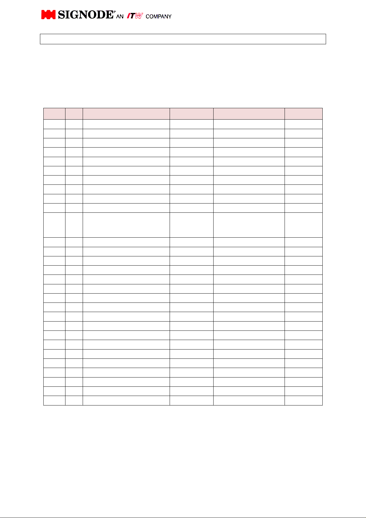
PARTS LIST
Description: Strapping head AK200-HDX
Drawing N°.: 464631
Version/Part-No.: 32 mm strap size 464631
25 mm strap size 464624
19 mm
strap size
464618
Pos. Qty.
21 2 Soc. head cap screw M8x20 912 0WT0856
22 4 Hex. screw M6x16 933 0WT0449
23 4 Washer, Form B 6,4 125 0WT2210
24 1 Pivot block 100.00-042 462952
25 2 Soc. head cap screw M8x20 912 0WT0856
26 1 Cover plate 464275
27 2 Thumb screw M5x16 464 462101
28 2 Hinge 40mm 529530.833 460444
29 4 Soc. head cap screw M4x10 912 0WT0813
30 4 Hex. nut M4 934 0WT2006
31 1 Timing belt pulley 100.00-060
32 1 Thread pin M4x6 914 462744
33 1 Lever shaft 100.00-018 460016
34 1 Washer 100.00-019 460018
35 2 Soc. head cap screw M6x20 912 0WT0841
36 1 Soc. head cap screw M8x16 7991 0WT0631
37 2 Thread pin M6x10 913 462663
38 2 Washer 25x35x0,5 988 0WT3124
39 1 Guard 100.10-023 462846
40 2 Soc. head cap screw M6x12 912 0WT0839
41 1 Seal ring 100.00-050 462497
42 3 Soc. head cap screw M6x16 7984 462988
1 Countersunk screw M6x12 7991 464607
43 1 Guard 100.00-051 462498
44 2 Soc. head cap screw M6x16 7984 462988
45 1 Mount. f. prox. switch 100.10-029 464607
46 2 Soc. head cap screw M5x16 912 0WT0825
47 2 Hex. Nut, self-lock. M5 985 0WT2103
48 2 Roll pin 5x14 1481 0WT2652
Description Drawing N°.
DIN/Version Part N°.
22 Z Standard
26 Z 0,75 KW-Mot.
18 Z 60 Hz Vers
462914
463353
462984
35
Page 50
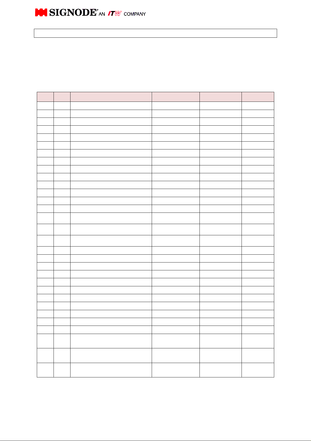
PARTS LIST
Description: Strapping head AK200-HDX
Drawing N°: 464631
Version/Part-No.: 32 mm strap size 464631
25 mm strap size 464624
19 mm
Pos. Qty.
49 10 Soc. head cap screw M3x16 912 0WT0805
50 1 Collar 100.00-031 463380
51 1 Link 100.00-032 460082
52 1 Angle for S92 100.00-037 Version 32 464609
53 2 Soc. head cap screw M4x6 912 0WT0811
54 5 Soc. head cap screw M3x6 912 0WT0801
55 1 Belt guard 100.00-038 460073
56 1 Soc. head cap screw M6x50 912 0WT0847
57 1 Soc. head cap screw M6x90 912 0WT0852
58 1 Release pin Version 32 464610
59 1 Timing belt pulley 100.00-056 462844
60 1 Timing belt HTD-960-8M-30 462845
61 1 Timing belt HTD-535-5M-15 462915
62 1 Conical element TLK 130, 22x47
63 3 Punching lever, complete
Description Drawing N°. DIN/Version Part N°.
strap size
464618
462843
Version 32 464601
64 1 Lever for pusher, complete
65 1 Lever, compl., 15 thick
66 1 Collar 150.00-026 464605
67 1 Motor mounting f. weld motor 464251
68 1 Cover for weld motor 464252
69 1 Timing belt HTD 318-3M-9 464253
70 1 Motor pulley 40 z 280413
71 1 Pulley 28 z 280412
72 1 Mount. plate for sensor Version 32 464689
73 2 Soc. head cap screw M5x12 912 0WT0824
74 4 Soc. head cap screw M3x16 912 0WT0805
75 4 Soc. head cap screw M4x10 912 0WT0813
76 1 Proximity switch „Strap stop“ IFM IN 5129 464400
77 1
78 1
79 1
Proximity switch „Shutter
open“
Proximity switch „Shutter
closed“
Proximity switch „Pre-tension
reached“
461764
461764
461764
Version 32 464603
Version 32 464611
36
Page 51
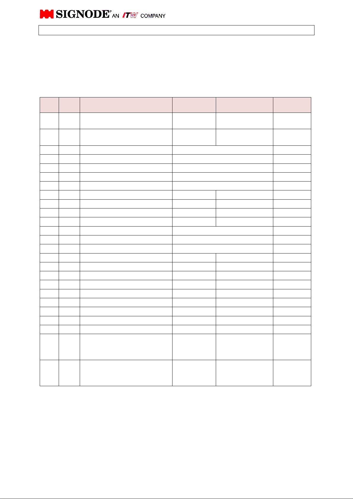
PARTS LIST
Description: Strapping head AK200-HDX
Drawing N°: 464631
Version/Part N°: 32 mm strap size 464631
25 mm strap size 464624
19 mm
strap size
464618
Pos. Qty. Description Drawing N°.
80 1
81 1
82 1 Drive motor 230 / 400 V, 3 Ph, 50 Hz 461059
Special drive motor 500 V, 3 Ph, 50 Hz 462291
270 / 480 V, 3 Ph, 60 Hz 462732
83 1 Weld motor EM 94-50 230 V, 50/60 Hz 464381
83a 2 Brushes for weld-motor EM 94-50 230 V 464382
83b 2 Brush holder 464383
83c 2 Brush cap 464384
83d 1 Amature assembly 464385
83e 1 Terminal connector 3 pot 464353
84 1 Base housing HAN 24 ASG 2RB 463346
85 1 Female insert HAN 24 E STI.S 463347
86 1 Cam follower KR 19 PP 464289
87 5 DU-bushing 463382
88 5 Roller, version 1 463377
89 5 Pin, version 1 463378
90 10 Bolt lock 461097
91 10 Countersunk screw M4x6 7991 462105
92 3 Snapper 462033
93 6 Grooved collar 462299
94 3 Adjustment screw 462298
95 3 Washer 462428
96 1 Gate, right
97 1 Gate, left
Proximity switch „Final tension
reached“
Proximity switch „Strap
disturbance“
461764
IFM IN 5129 464400
DIN/Version Part N°.
Version 32 mm
25 mm
19 mm
Version 32 mm
25 mm
19 mm
464638
464461
464312
464639
464462
464313
37
Page 52
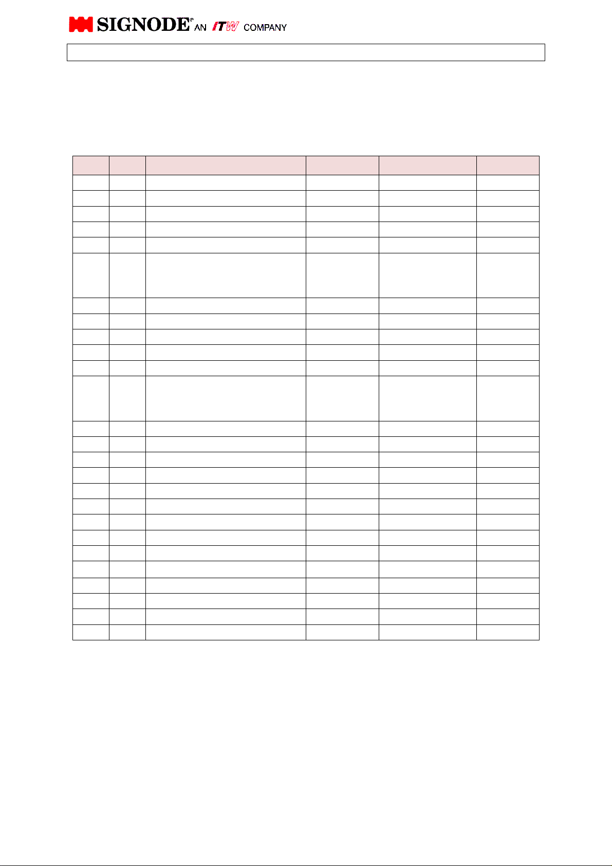
PARTS LIST
Description: Strapping head AK200-HDX
Drawing N°: 464631
Version/Part N°: 32 mm strap size 464631
25 mm strap size 464624
19 mm
strap size
464618
Pos. Qty. Description Drawing N°.
98 2 Spring retainer 072400
99 2 Spring retainer 040460
100 4 Gate, spring 072432
101 1 Switch lever 462133
102 1 Pressure spring D-050 461754
103 1 Feed wheel ring
104 42 Belleville washer 462995
105 1 Pressure spring D-337 461420
106 1 Guide shaft 460648
107 1 Pressure spring D-313 Q 462484
108 1 Pressure spring D-279 461430
109 1 Segment
110 1 Cover plate 464278
111 4 Countersunk screw M4x10 7991 0WT0601
112 8 Lockwasher 4 7980 0WT2254
113
114 22 Chain link 464477
115 12 Ball bearing self aligning 2200 2RS 464502
116 11 Pin 464470
117 22 Lock ring extern 10mm 471 0WT2808
118 2 Chain bracket 460009
119 2 Pin
120 4 Washer B 6,4 125 0WT2210
121 4 Soc. head cap screw M6x12 6912 462109
122 2 Washer 10/16x1 464620
123 2 Washer 10/16x2 464621
DIN/Version Part N°.
Version 32 mm
25 mm
19 mm
Version 32 mm
25 mm
19 mm
Version 32 mm
464633
464635
464475
464648
464649
464650
464622
38
Page 53
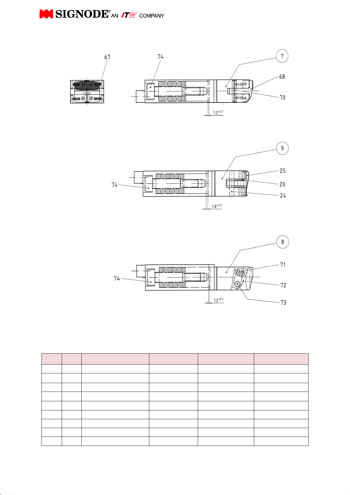
Pos. Qty.
Adjustment after inserting of Belleville washers
and fitting bolt key 74 tightened up to limit strap
Proper arrangement for Belleville washers: 4 pcs. spring kits of 6 each
Adjustment after inserting of Belleville washers
and fitting bolt key 74 tightened up to limit strap
Proper arrangement for Belleville washers: 6 pcs. spring kits of 4 each
Adjustment after inserting of Belleville washers
and fitting bolt key 74 tightened up to limit strap
Proper arrangement for Belleville washers: 4 pcs. spring kits of 6 each
Description Drawing N°. DIN/Version Part N°.
67 4 Pressure spring D-063 F 464239
68 1 Gripper plate
Version 32 mm
464675
69
70 1 Spring pin
∅5 x 26
7346 464730
71 1 Pressure spring D-134 461422
72 1 Pressure spring 464213
73 1 Pin 6x36 6325 0WT2515
74 3 Hex. fitting bolt 464227
75 72 Belleville washer 23x12,2 x 1,25 464258
39 a
Page 54
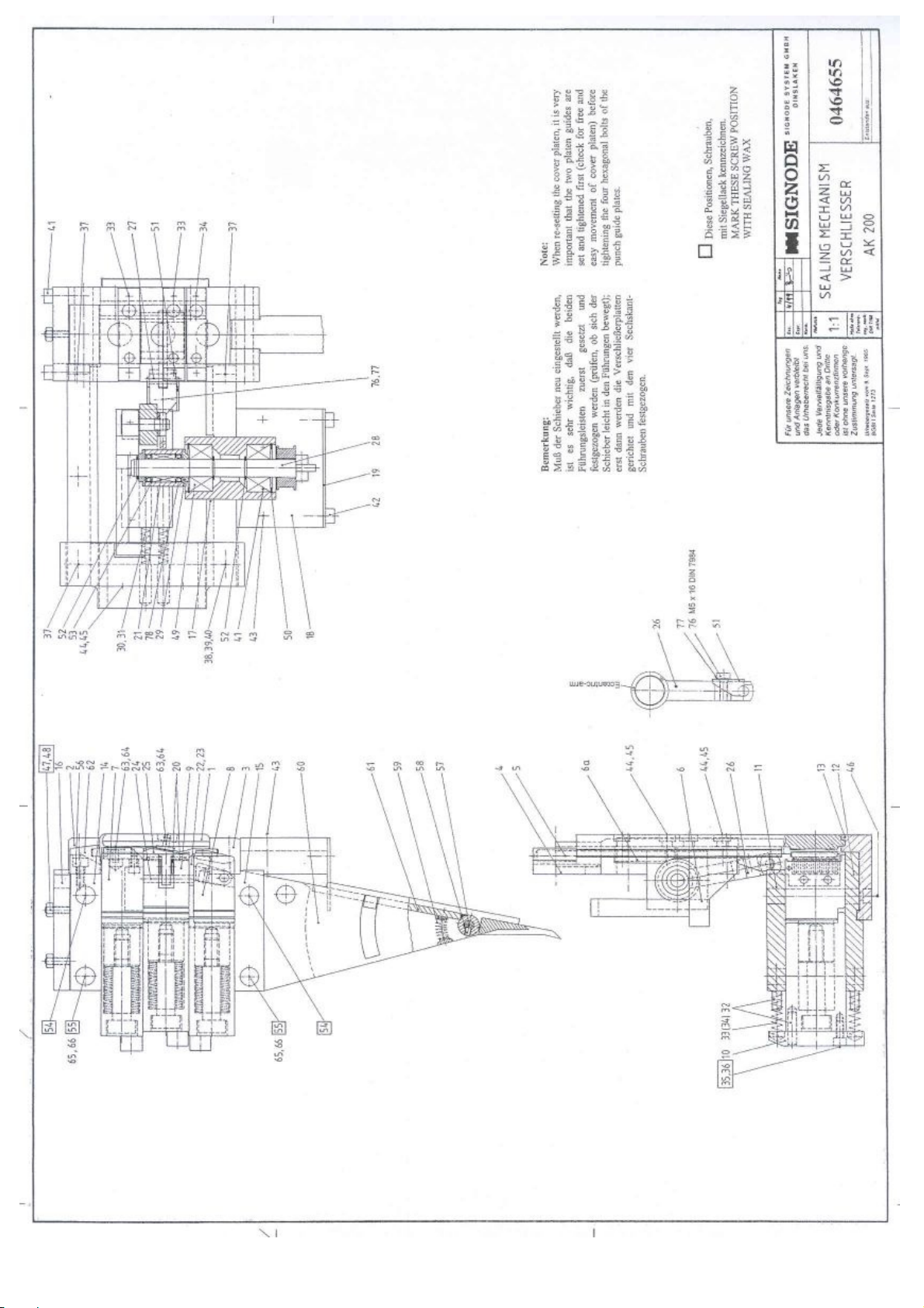
39 b
Page 55
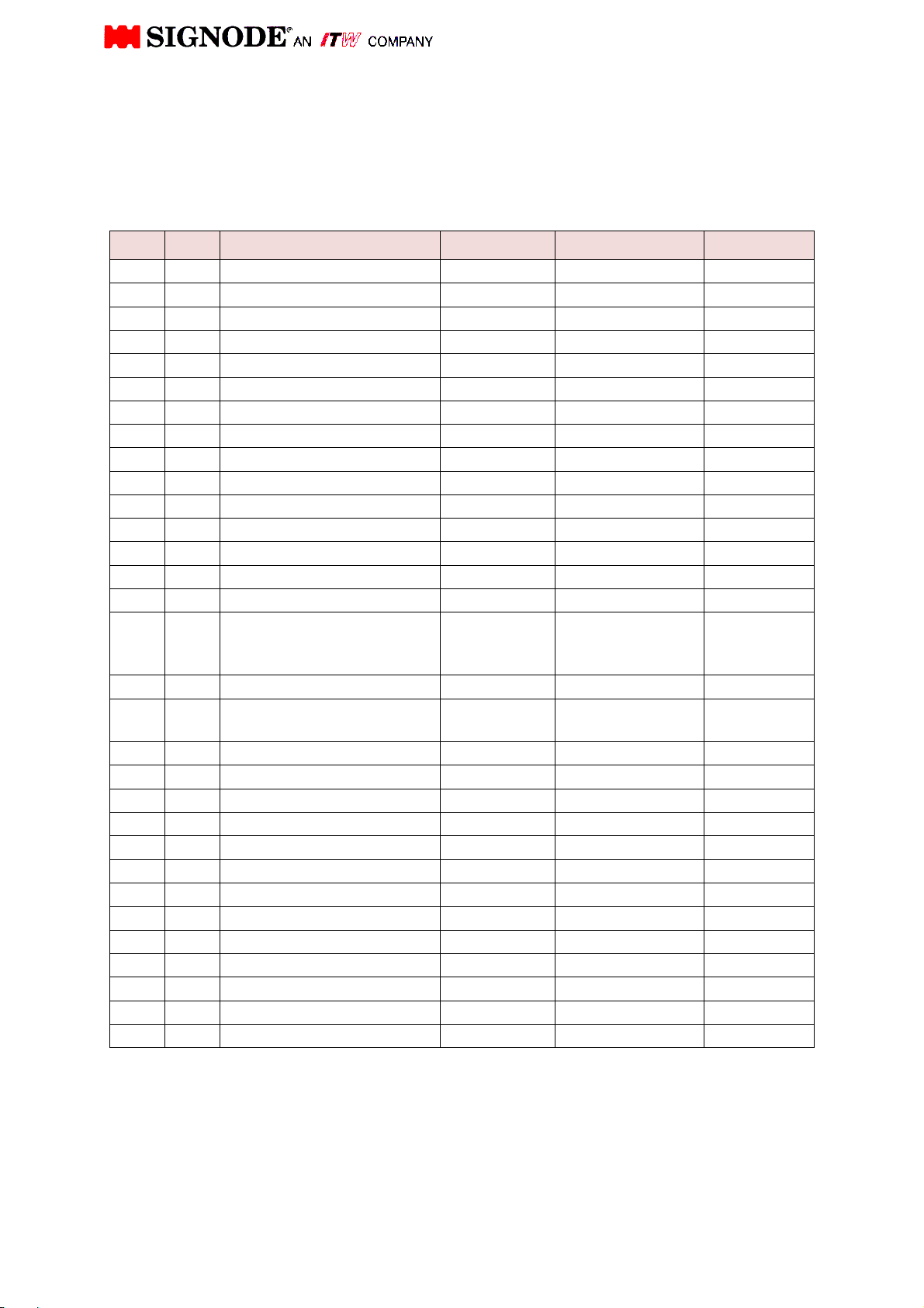
PARTS LIST
Description: Sealing mechanism AK200-HDX
Drawing N°: 464655
Version/Part N°: 32 mm strap size 464655
25 mm strap size 464656
19 mm
strap size
464657
Pos. Qty. Description Drawing N°. DIN/Version Part N°.
1 1 Shutter, complete Version 32 464660
2 1 Upper guide rail 464202
3 1 Lower guide rail 464362
4 1 Holding plate Version 32 464665
5 1 Spring retainer Version 32 464666
6 1 Carrier for pusher 464451
6a Spring retainer for shutter 464447
7 1 Loop grip Version 32 464676
8 1 Gripper, complete Version 32 464669
9 1 Vibrator support Version 32 464672
10 3 Cross bar 464216
11 1 Sealer plate, rear Version 32 464664
12 1 Sealer plate, front Version 32 464662
13 1 Pressure pad Version 32 464663
14 1 Spacer 464220
Version 32 mm
15 2 Spacer
16 1 Plate 464222
17 1
18 1 Holder for bearing block 464224
19 1 Cover plate 464225
20 4 INA flat cage needle roller FF 2010 464228
21 1 Needle bearing NK 12/16 464373
22 1 Cutter blade Version 32 464687
23 0 Spacer 464232
24 2 Vibrator bolt 464233
25 1 Vibrator Version 32 464677
26 1 Eccentric arm 464368
27 1 Bolt for Eccentric arm 464371
28 1 Eccentric shaft 464367
29 2 Spacer 464369
30 2 Pin 5 M6 x 55 6325 464511
Bearing block for eccentric
shaft
464366
25 mm
19 mm
464683
464459
464221
40
Page 56
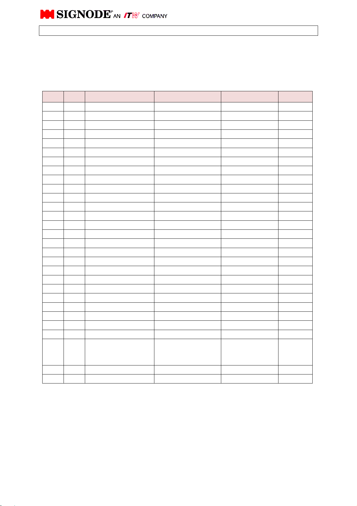
PARTS LIST
Description: Sealing mechanism AK200-HDX
Drawing N°: 464655
Version/Part N°: 32 mm strap size 464655
25 mm strap size 464656
19 mm
strap size
464657
Pos. Qty. Description Drawing-No. DIN/Version Part-No.
31 2 Pressure spring KM-3235 120 lg 464686
32 9 Pin 6x24 6325 0WT2512
33 4 Pressure spring D-231 461428
34 2 Pressure spring D-230-A 461429
35 3 Soc. head cap screw M5x12 912 0WT0824
36 3 Washer 5 mm 7980 0WT2255
37 4 Soc. head cap screw M6x25 912 0WT0842
38 1 Soc. head cap screw M6x40 912 0WT0845
39 1 Hex. Nut, self-lock. M6 985 0WT2104
40 1 Washer Form B 6,4 125 0WT2210
41 6 Soc. head cap screw M6x20 912 0WT0841
42 2 Soc. head cap screw M6x10 912 0WT0838
43 2 Soc. head cap screw M6x30 912 0WT0843
44 8 Soc. head cap screw M6x10 7984 462120
45 8 Schnorr-safety disk 6 mm H1235/6 462122
46 2 Soc. head cap screw M6x10 912 0WT0838
47 2 Thread pin M6x16 916 0WT1847
48 2 Hex. nut M6 934 0WT2008
49 2 Ball bearing W 201 PP 464372
50 2 Lock ring, intern 32 mm 472 0WT2922
51 1 Pin keeper 464370
52 3 Lock ring, extern 12 mm 471 0WT2810
53 2 Lock ring, intern 19 mm 472 0WT2913
54 2 Fitting screw M10x11k6x80 610 460398
55 2 Fitting screw M10x11k6x90 610 464513
56 1 Soc. head cap screw M5x12 912 0WT0824
57 1 Bolt
Version 32 mm
25 mm
19 mm
58 1 Thread pin M4x6 914 0WT1701
59 1 Spring D-166 460320
464681
464457
464316
41
Page 57
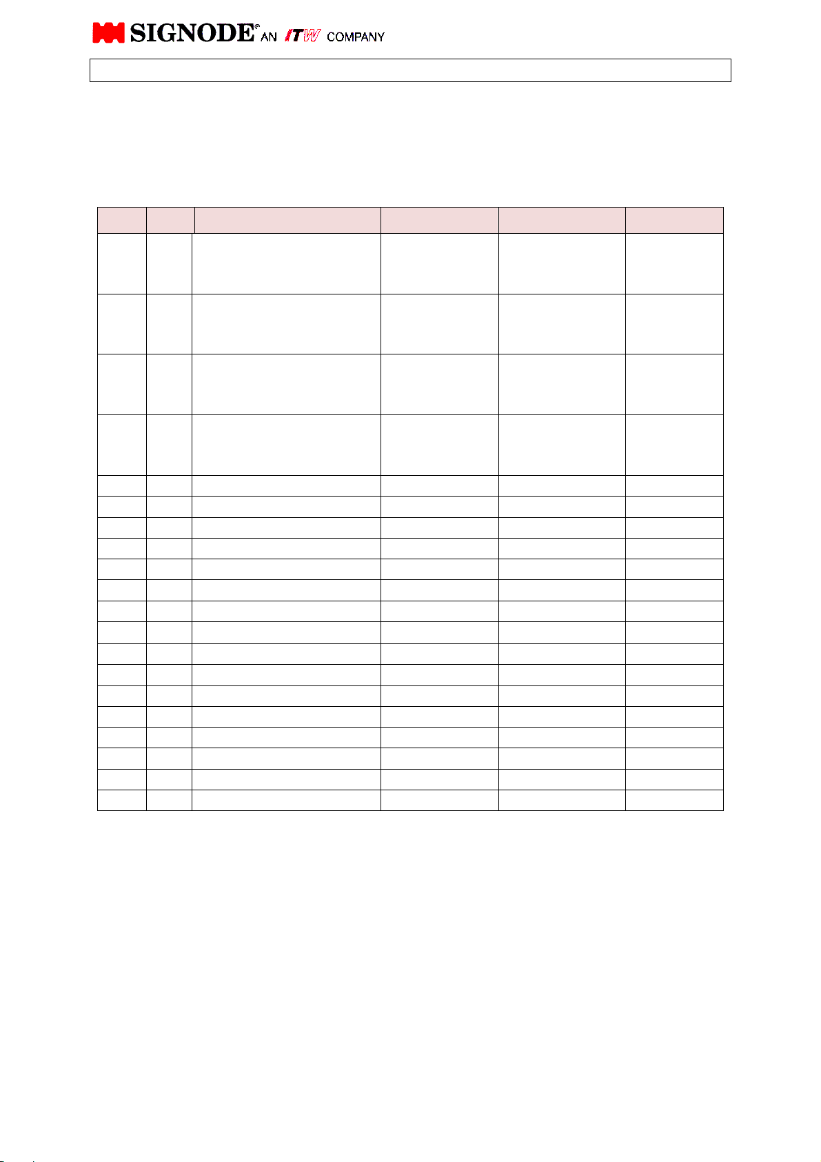
PARTS LIST
Description: Sealing mechanism AK200-HDX
Drawing N°: 464655
Version/Part N°: 32 mm strap size 464655
25 mm strap size 464656
19 mm
Pos. Qty. Description Drawing N°. DIN/Version Part N°.
60 1 Strap guide wedge
Sub Assy.
60a 1
61 1 Ejector gate
62 1 Guide
63 2 Gripper pad (shutter) 464659
64 2 Lock ring 4,0 6799 0WT2949
65 2 Hex. nut self lock M10 985 0WT2107
66 2 Washer 10,5 125 0WT2212
67 4 Pressure spring D-063 F 464239
68 1 Gripper plate, special Version 32 464675
69
70 1 Spring pin
71 1 Pressure spring D-134 461422
72 1 Pressure spring 464213
73 1 Pin 6x36 6325 0WT2515
74 3 Hex. fitting bolt 464227
75 72 Belleville washer 23x12,2x1,25 464258
76 1 Soc. head cap screw M5x16 7984 464406
77 1 Schnorr-safety-disk H1235/5 464398
78 2 Oil-seal G12x19x3 INA 464374
Strap guide wedge
(Pos. 57,58,59,60 + 61)
strap size
464657
∅5 x 26
Version 32 mm
25 mm
19 mm
Version 32 mm
25 mm
19 mm
Version 32 mm
25 mm
19 mm
Version 32 mm
25 mm
19 mm
7346 464730
464679
464684
464517
464682
464685
464516
464680
464456
464315
464678
464452
464317
42
Page 58
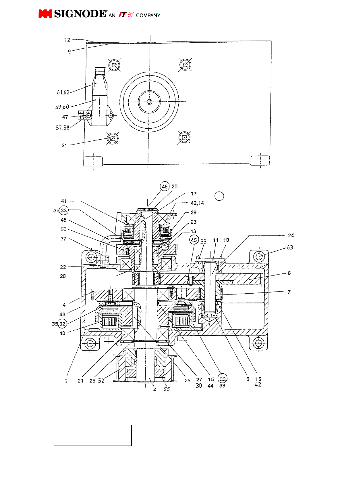
Transmission
Insert these screws
with loctite
If for any reason the transmission will be opened, never oil or grease parts.
It will destroy the function of the clutch
100.36
43
Page 59
PARTS LIST
Description: Transmission AK200-HDX
Drawing N°: 100.36
Version: 15 mm pulley
Part N°: 462953 in exchange Part-No.: 462954
Pos. Qty. Description Drawing N°. DIN/Version Part N°.
1 1 Housing 100.06-001 461622
2 1 Shaft 100.36-002 462847
3
4 1 Gear 100.06-004 460619
5
6 1 Gear 100.06-006 460622
7 1 Gear 100.06-007 462924
8 1 Washer 100.06-008 460625
9 1 Gasket 12x3 460340
10 1 Shaft 100.06-010 460626
11 1 Cover 100.06-011 460627
12 1 Cover 100.06-012 460628
13 1 Spacer 100.06-015 Version 2 462951
14 1 Spacer 100.06-016 460631
15 1 Spacer 100.06-017 460634
16 1 Washer 15x21x1,0 988 0WT3112
17 1 Key A5x5x30 6885 462119
18
19
20 1 Washer GN 184-36 460633
21 2 Ball bearing 6206-2RS 207495
22 1 Ball bearing 6008-2RS 460356
23 2 Ball bearing 6002-2RS 462955
24 2 Needle cage HK 1516 2RS 462982
25 1 Key A8x7x28 6885 462131
44
Page 60
PARTS LIST
Description: Transmission AK200-HDX
Drawing N°: 100.36
Version: 15 mm pulley
Part N°: 462953 in exchange Part-No.: 462954
Pos. Qty. Description Drawing N°. DIN/Version Part N°.
26 2 Lock ring, extern 30x1,5 471 0WT2826
27 2 Lock ring, intern 62x2 472 0WT2939
28 1 Lock ring, extern 40x1,75 471 0WT2830
29 1 Lock ring, intern 32x1,2 472 0WT2922
30 2 Washer 50x62x0,1 988 462930
31 4 Soc. head cap screw M8x12 6912 462945
32 3 Soc. head cap screw M6x16 7984 462988
33 7 Soc. head cap screw M4x10 6912 462121
34
35 5 Schnorr-safety disk H1235/6 462122
36 5 Schnorr-safety disk H1235/4 462123
37 1 Hex. nut M8 934 0WT2009
38
39 3 Washer B4,3 9021 462125
40 1 Clutch 60Nm Y22 complete (462943)
Armature 460637
Magnet 460640
Rotor 460647
41 1 Clutch 15Nm Y37 complete 460642
42 3 Washer 15x21x0,1 988 462126
43 1 Lug 0B0 604/10 462451
44 3 Washer 30x42x0,1 988 462127
45 4 Soc. head cap screw M6x10 7984 462120
46 1 Countersunk screw M6x20 7991 0WT0623
47 2 Soc. head cap screw M3x10 912 0WT0803
48 1 Holder 100.06-013 460630
49
45
Page 61
PARTS LIST
Description: Transmission AK200-HDX
Drawing N°: 100.36
Version: 15 mm pulley
Part N°: 462953 in exchange Part-No.: 462954
Pos. Qty. Description Drawing N°. DIN/Version Part N°.
50 1 Hub and gear, complete
51
52 1 Belt pulley 100.10-043
53
54
55 1 Conical element TLK-130
56
57 1 Metal connection
58 1 Counter nut
59 1 Receptacle, lower part 0900030801 Harting 461691
60 1 Pin insert
61 1 Tüllen-housing
62 1 Bushing insert
63 4 Soc. head cap screw M8x25 912 0WT0857
PG-7 /
2080079
PG-7 /
0482650
Version 15 462949
462848
462843
463348
463349
461693
463350
461692
46
Page 62
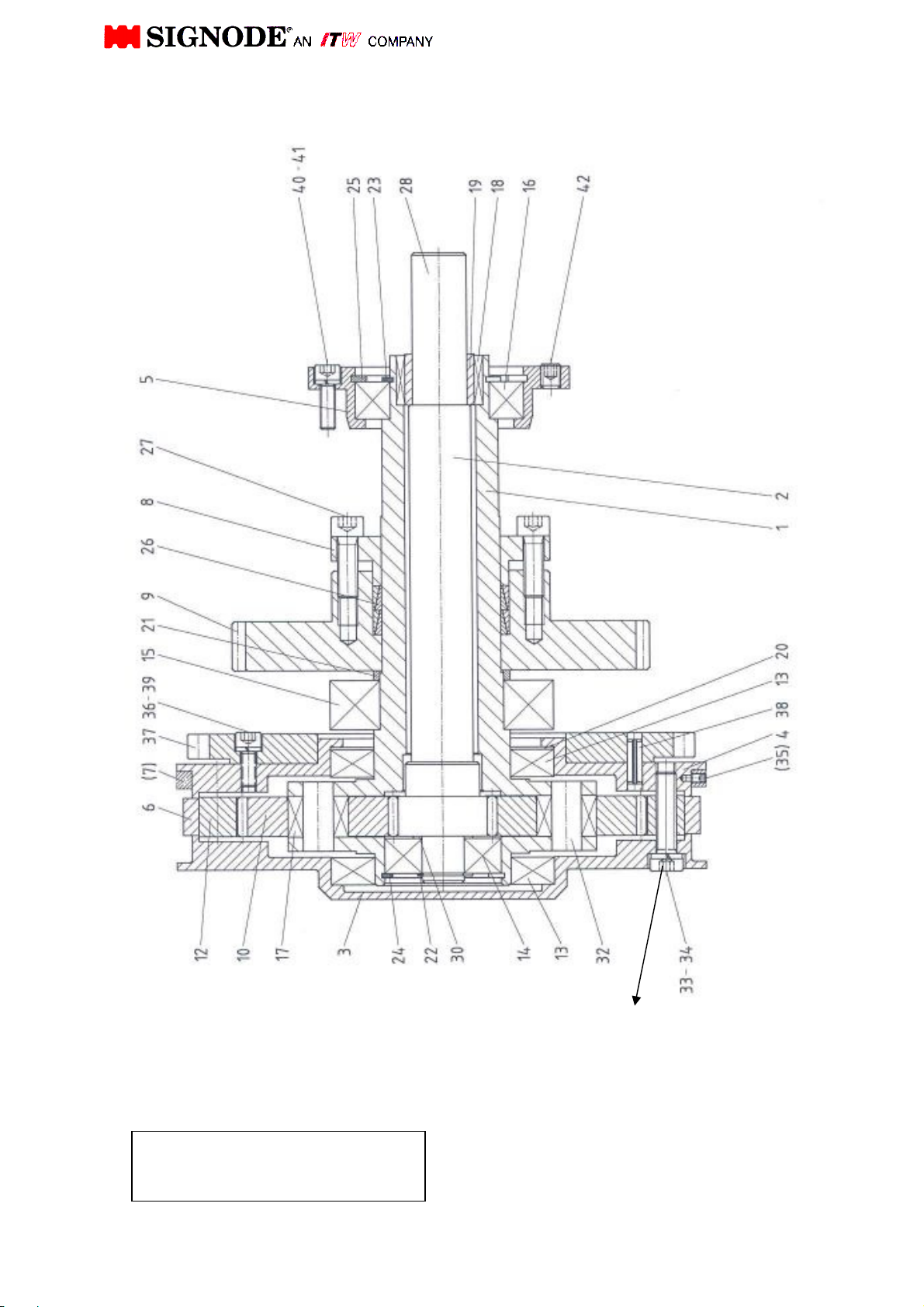
Strap drive
AK200HDX
464626
If you exchange the feed wheel ring please exchange the
6 pcs. soc. hd. cap screw also.
6 pcs. soc. hd. cap screw property class 10.9 must be
tightened symmetrically by 35 Nm turning moment.
47
47
Page 63
PARTS LIST
Description: Strap drive AK200-HDX
Drawing N°: 464626
Version/Part N°: 32 mm strap size 464626
25 mm strap size 464627
19 mm
strap size
464628
Pos. Qty. Description Drawing N°. DIN/Version Part N°.
1 1 Planetary gear shaft 100.03-001 464491
2 1 Shaft with gear 462976
3 1 Planetary gear cover
4 1 Planetary gear flange 464533
5 1 Bearing flange 100.03-005 460508
6 1 Feed wheel ring
7 2 Side guide ring only with Version 19 mm 464634
8 1 Tension ring 464494
9 1 Gear Z65 464493
10 2 Gear 100.03-010 462012
11
12 1 Internal gear 464532
13 2 Ball bearing 16011 460348
14 1 Ball bearing 6303-2RS 460343
15 1 Ball bearing 6210-2RS 460355
16 1 Ball bearing 6008-2RS 460356
17 2 Needle bearing NKI 1216 460324
18 1 Needle cage HK 2820-2RS 460326
19 1 Needle bearing ring IR 22x28x20,5 460327
20 1 Nilos ring 16011 461103
21 1 Spacer 100.03-013 460578
Version 32 mm
25 mm
19 mm
Version 32 mm
25 mm
19 mm
464629
464629
464629
464633
464635
464475
48
Page 64
PARTS LIST
Description: Strap drive AK200-HDX
Drawing N°: 464626
Version/Part N°: 32 mm strap size 464626
25 mm strap size 464627
19 mm
strap size
464628
Pos. Qty. Description Drawing N°. DIN/Version Part N°.
22 1 Lock ring
23 1 Lock ring
24 1 Lock ring
25 1 Lock ring
26 2 Conical spring element
27 8 Soc. head cap screw
28 1 Conical element TLK-130 462843
29
30 1 Washer 17x24x1 988 462114
31
32 2 Pin 100.03-014 175 460580
33 6 Lock Washer 8 7980 0WT2254
34 6 Soc. head cap screw
35 3 Thread pin M4x8
36 22 Lock washer 6 7980 0WT2256
37 1 Gear 100.13-015 462458
38 2 Roll pin 6x18 1481 0WT2670
39 16 Soc. head cap screw M6x16/10.9 912 462469
40 4 Soc. head cap screw M6x20 912 0WT0841
41 4 Washer 6 7980 0WT2256
42 4 Thread pin M8x10 913 0WT1809
17x1
40x1,75
47x1,75
68x2,5
TLK300
M8 x 30
M8x35/10.9
471
471
472
472
0WT2815
0WT2830
0WT2931
0WT2942
464495
912/10.9 464496
7984
464534
916
(only Version 19)
463449
49
Page 65
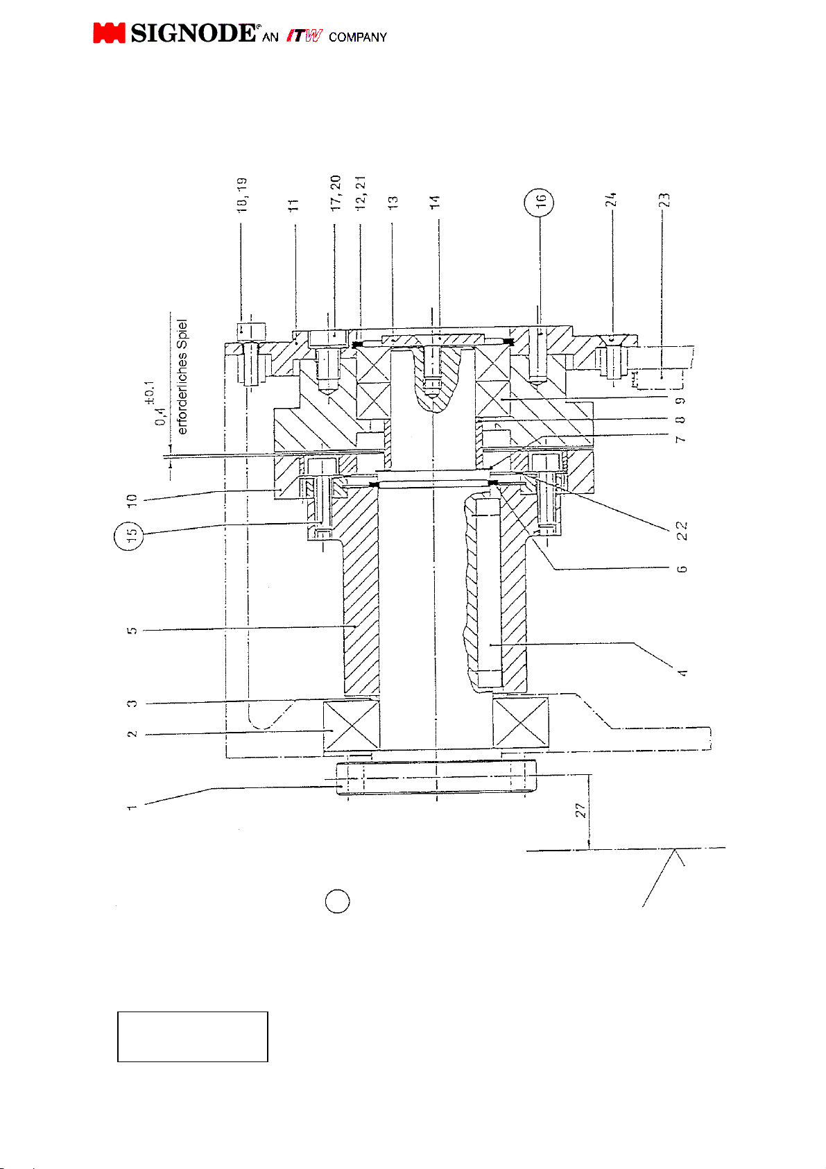
Brake
100.14
with loctite
50
Strap center Insert these screws
50
Page 66
PARTS LIST
Description: Brake AK200-HDX
Drawing N°: 100.14
Version/Part N°: 462459 (Part No. for complete list)
Pos. Qty. Description Drawing N°. DIN/Version Part N°.
1 1 Pinion shaft 100.14-001 462460
2 1 Ball bearing 6208-2RS 462461
3 1 Washer 40x50x2 988 462140
4 1 Key A12x8x67 6885 462466
5 1 Carrier-hub 100.14-002 462462
6 1 Lock ring, extern 40 471 0WT2830
7 10 Washer 30x42x0,1 988 462127
8 1 Spacer 100.14-003 462463
9 2 Ball bearing 6006-2Z 463345
10 1 Gear brake 24.5602345 462464
11 1 Cover 00.14-004 462465
12 1 Lock ring, intern 55 472 0WT2935
13 1 Washer 36 GN 184 462529
14 1 Countersunk screw M6X16 7991 0WT0622
15 3 Hex. head cap screw M6x20 912 0WT0841
16 2 Roll pin 6x18 1481 0WT2670
17 4 Hex. head cap screw M8x16 912 0WT1030
18 6 Hex. head cap screw M6x16 912 0WT0840
19 6 Lock washer 6 7980 0WT2256
20 4 Lock washer 8 7980 0WT2257
21 5 Washer 45x55x0,1 988 462534
22 1 Membrane (spring) (included in pos. 10) 462780
23 1 Plug 462908
24 2 Countersunk screw M6x10 7991 0WT0620
51
Page 67
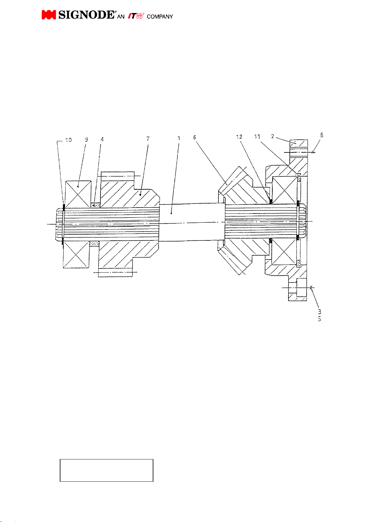
Intermediate shaft
464291
52
Page 68
PARTS LIST
Description: Intermediate AK200-HDX-19/25
Drawing N°: 464291
Version/Part N°: 464291
Pos. Qty. Description Drawing N°. DIN/Version Part N°.
1 1 Shaft with involute connection 462966
2 1 Cover 150.14-002 462546
3 4 Soc. head cap screw M6x20 912 0WT0841
4 1 Spacer 100.05-004 462034
5 4 Lock washer 6 7980 0WT2256
6 1
7 1 Gear with involute connection 462967
8 4 Thread pin, flat M8x10 913 0WT1809
9 2 Ball bearing 6304-2RS 460359
10 2 Lock ring, extern 20x1,2 471 0WT2818
11 1 Lock ring, intern 52x2 472 0WT2934
12 1 Washer 20x28x1 988 462117
Bevel gear with involute
connection
462963
53
Page 69
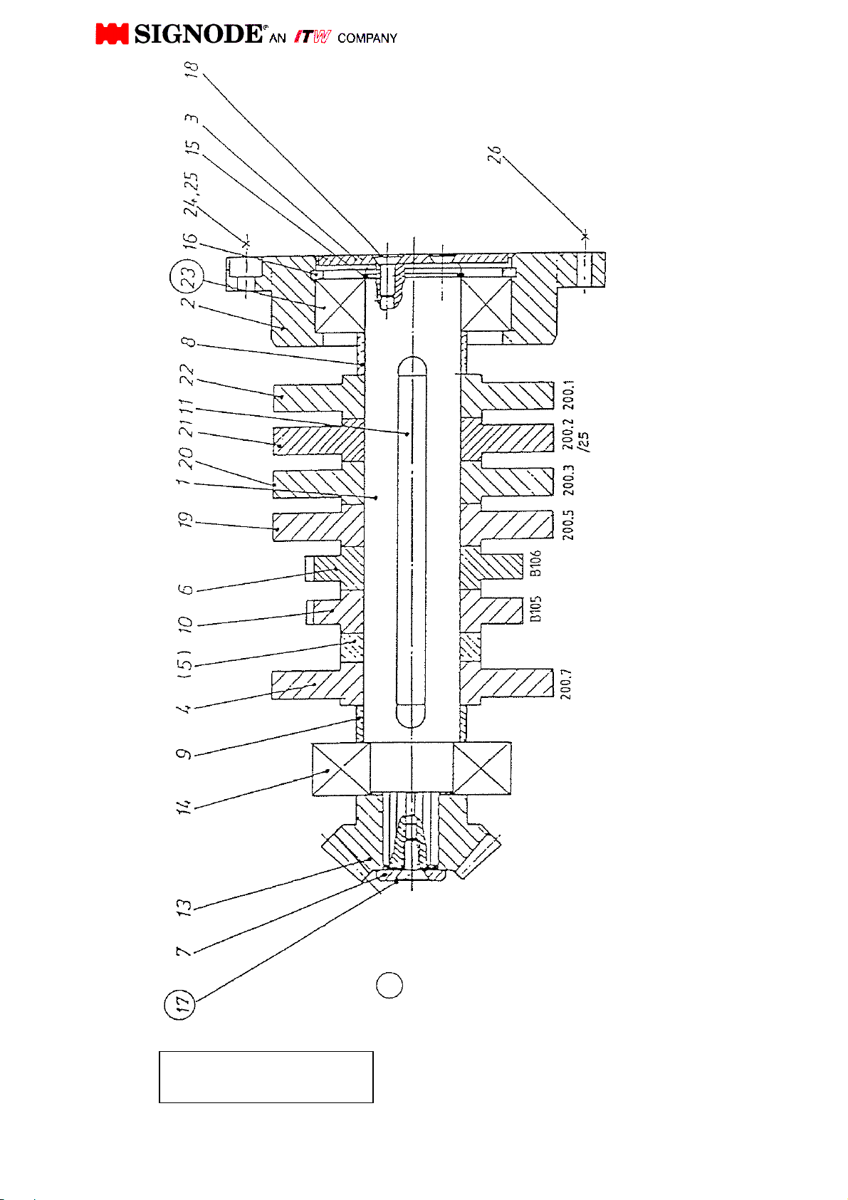
Camshaft
Note:
When exchanging the cams, please note
that the imprinted number points towards
in the conical gear wheel of 4 each
Insert these screws
with loctite
464613
54
Page 70
PARTS LIST
Description: Camshaft AK200-HDX
Drawing N°: 4644613
Version/Part N°: AK200-HDX-HT/2 464613
Pos. Qty. Description Drawing N°. DIN/Version Part N°.
1 1 Shaft 462964
2 1 Cover 100.04-002 460582
3 1 Cover 100.04-003 460584
4 1 Cam 200.7/MT 464335*
5
6 1
7 1 Washer 100.04-014 460600
8 1 Spacer
Actuator disc „Final tension
reached“
B106 464397
463418
9 1 Spacer
10 1
11 1 Key B10x8x125 6885 462115
13 1
14 1 Ball bearing 6306 2RS 460354
15 1 Lock ring, extern 30x1,5 471 0WT2828
16 1 Lock ring, intern 72x2,5 472 0WT2944
17 1 Countersunk screw M8x16 7991 0WT0631
18 2 Countersunk screw M8x10 7991 0WT0620
19 1 Cam 200.5
20 1 Cam 200.3/A
21 1 Cam 200.2 / 25
22 1 Cam 200.1/A
23 1 Freewheel f. camshaft KK35 462538
24 4 Soc. head cap screw M6x20 912 0WT0841
25 4 Lock washer 6 7980 0WT2256
26 4 Thread pin M8x10 913 0WT1809
* Cam 200.7/LT for low tension 464334
*
** only for camshaft AK200.7/LT
Actuator disc „Pre-tension
reached“
Bevel gear with involute
connection
Cam 200.7/MT for medium
tension
B105 464396
462963
464327
463419
464617
464616
464615
464614
55
Page 71
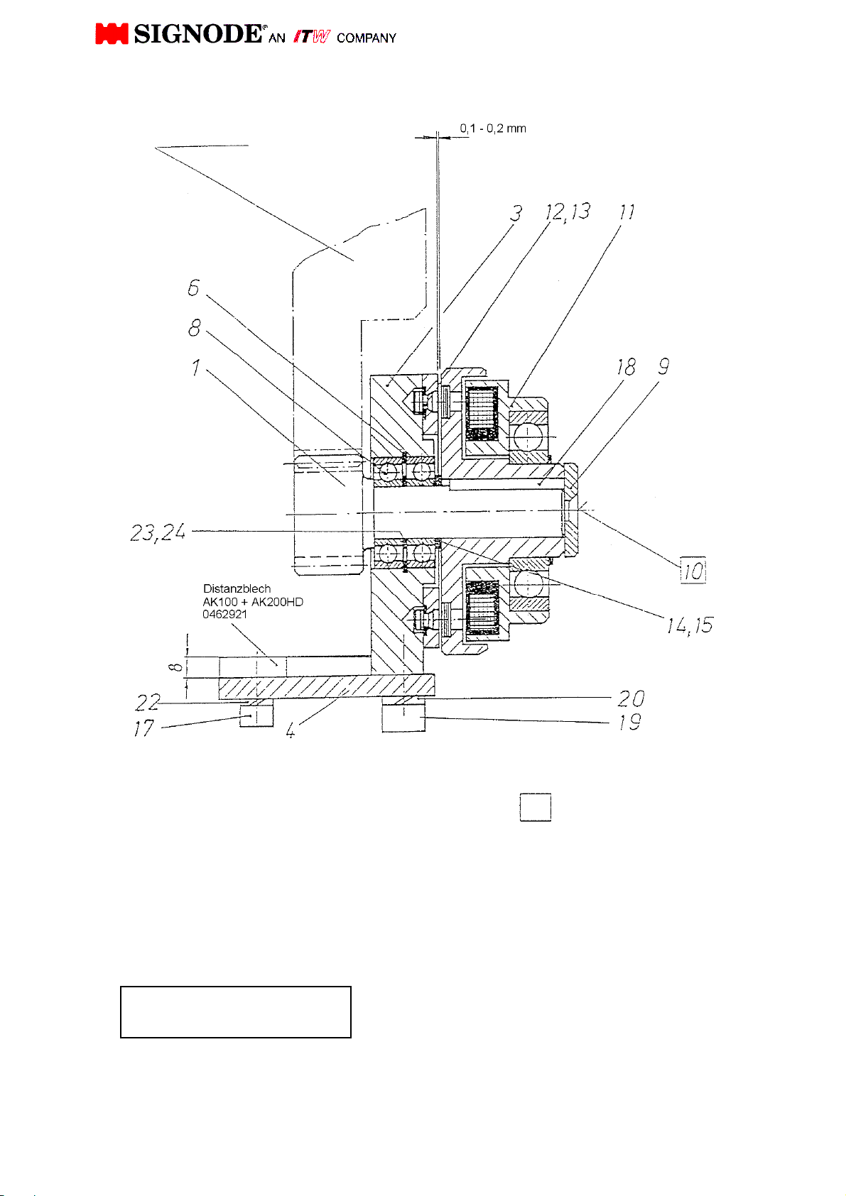
Brake "Camshaft turn"
Strap drive pos. 9
necessary clearance
Insert these screws
with loctite
150.15
56
Page 72
PARTS LIST
Description: Camshaft brake AK200-HDX
Drawing N°: 150.15
Version/Part N°: 462840
Pos. Qty. Description Drawing N°. DIN/Version Part N°.
1 1 Axle with gear 463314
3 1 Bearing bock 150.15-003 462837
4 1 Mounting plate 150.15-004 462838
6 1 Lock ring, intern 32 472 0WT2922
8 2 Ball bearing 6002 2RS 462955
9 1 Washer 28 GN 184 Ganter 460633
10 1 Countersunk screw M6x16 7991 0WT0622
11 1 Clutch coupling, compl. 15Nm 100.06 460642
12 3 Schnorr-lock washer H1235/4 462123
13 3 Soc. head cap screw M4x10 6912 462121
14 1 Washer 15x21x0,5 988 0WT3110
15 ca 6 Washer (used as necessary) 15x21x0,1 988 462126
18 1 Key A5x5x30 6885 462119
19 2 Soc. head cap screw M8x20 912 0WT0856
20 2 Lock washer 8 7980 0WT2257
22 3 Lock washer 6 7980 0WT2256
23 1 Washer 15x21x0,2 988 0WT3108
24 1 Washer 15x21x1,0 988 0WT3112
57
Page 73
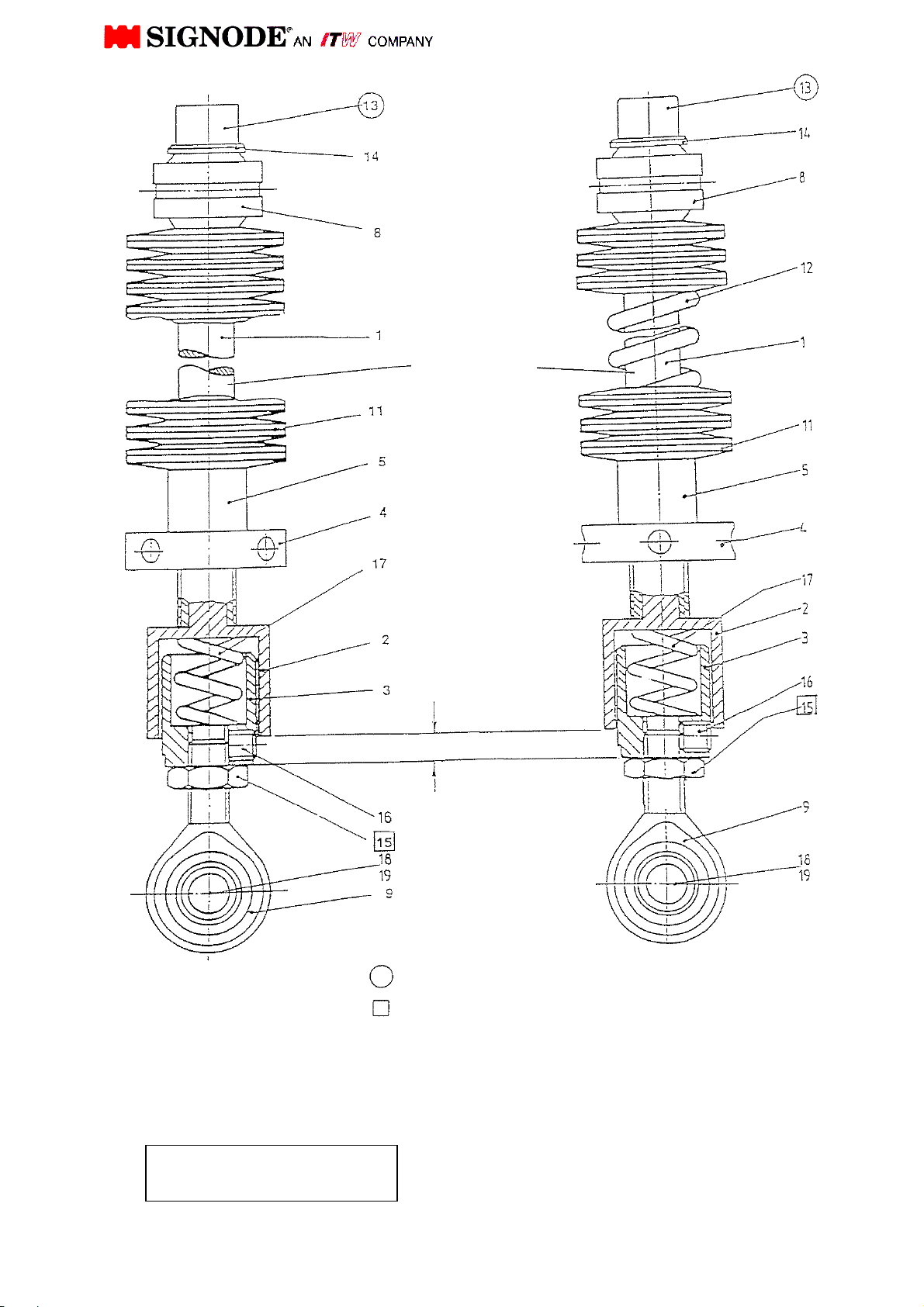
with sealing wax
shaft after approx.
Spring assembly
with strap
Note:
Apply normal
commercial
grease to the
20.000 strap
cycles
(or after 1 month)
5 mm - 6 mm
Spring stroke
being inserted
Insert these screws
with loctite
Mark these screw position
100.07
58
Page 74
PARTS LIST
Description: Spring assembly AK200-HDX-19/25
Drawing N°: 100.07 soft
Version/Part N°: 462809
Pos. Qty. Description Drawing N°. DIN/Version
1 1 Guide shaft 100.07-001 460648
2 1 Sleeve 100.07-002 460649
3 1 Spring sleeve 100.07-003 460650
4 1 Adjustment nut 100.07-004 460653
5 1 Spacer 100.07-005 460654
6
7
8 1 Swivel bearing GE 14 PB 460657
9 1 Toggle head SAK 10 ESA 460656
10
11
12 (1) Compression spring D-337 461420
13 1 Soc. head cap screw M10x15 912 0WT0870
14 1 Washer B 10,5 125 0WT2212
15 2 Hex. nut M10 439 0WT2057
16 1 Thread pin M8x6 916 462128
17 1 Compression spring D-279 461430
18 2 Washer 6,4 125 0WT2210
19 1 Soc. head cap screw M6x10 912 0WT0838
42 (16)
Belleville washer 40x14,3x1,5x2,75 460658
Part N°.
59
Page 75
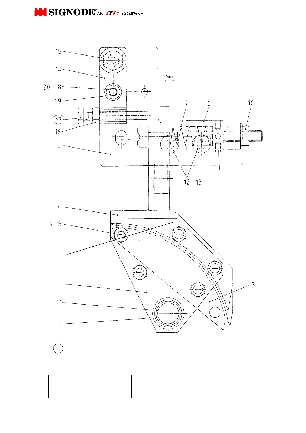
head without strap the bearings of chain
compr. Spring pos. 7 after
Insert
guide with spring
9, 21
9, 22
Adjustment pos. 17 without strap in
must not contact the feed wheel ring.
464643
Adjustment test, without strap in head
clearance between pos. 4 and pos. 7
approx. 1mm.
Readjust during wear of feed wheel ring.
Attention!
When adjusting
compression spring do
not risk any strap
deformation
Reduce pre-tension of
exchange of feed wheel
ring, so that clearance of
1 mm is provided
60
Page 76
PARTS LIST
Description: Insert guide with spring AK200-HDX
Drawing N°: 464643
Version/Part N°: 32 mm strap size 464643
25 mm strap size 464644
19 mm strap size 464645
Pos. Qty. Description Drawing N°. DIN/Version Part N°.
1 1 Hub 464646
2 1 Plate front 100.09-002 460669
Version 32 mm
3 1 Segment 100.09-003
4 1 Strap guide 100.15-004 Version 32 mm 464647
5 1 Cover plate 464536
6 1 Adjustment screw 100.15-006 462482
7 1 Compression spring D-313 Q 462484
8 1 Fitting bolt M8x9k6x60 610 464651
9 5 Hex. nut M8 934 0WT2009
10 1 Hex. nut M10 934 0WT2010
11 2 Bushing 460380
12 2 Countersunk screw M8x25 7991 0WT0633
13 2 Thread insert 30208016 462021
14 1 Stop device 464499
15 1 Catch pin GN617 6AK 464498
16 1 Hex. Nut M8 934 0WT2009
17 1 Hex. Screw M8 x 60 931 0WT0561
18 1 Soc. head cap screw M8 x 30 912 464512
19 2 Washer 8.4 125 0WT2210
20 1 Hex. nut self lock. M8 985 0WT2106
21 3 Fitting bolt M8x9k6x56 DIN 610 464653
22 1 Plate rear 464652
25 mm
19 mm
464648
464649
464650
61
Page 77
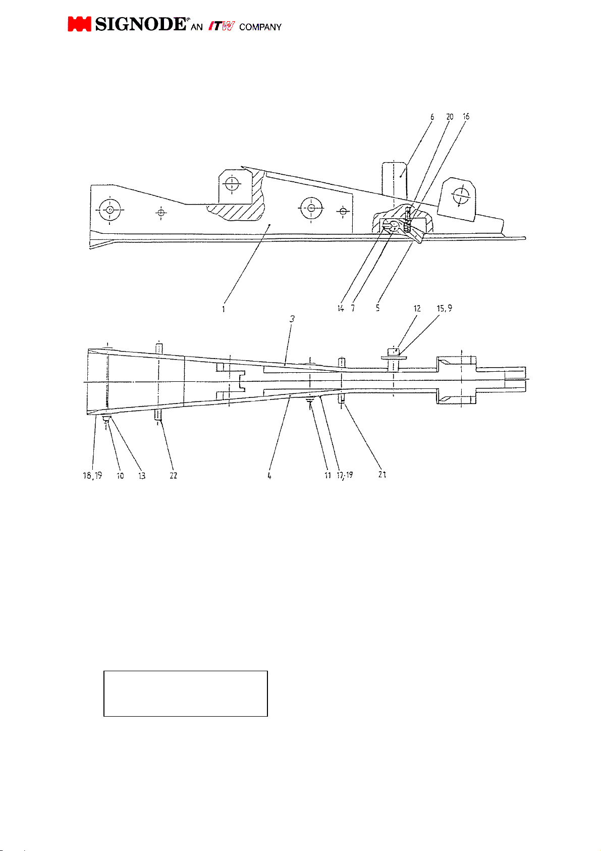
Insert guide wedge
464636
62
Page 78
PARTS LIST
Description: Strap guide wedge AK200-HDX
Drawing N°: 464636
Version/Part N°: 32 mm strap size 464636
25 mm strap size 464665
19 mm strap size 464310
Pos. Qty. Description Drawing N°. DIN/Version Part N°.
464637
464460
464311
464638
464461
464312
464639
464462
464313
464464
462005
464640
464463
461521
461754
Version 32 mm
1 1 Strap guide wedge
3 1 Gate, right
4 1 Gate, left
5 1 Switch lever 1050.08-008 462133
6 1 Switch slip
7 1 Pin
9 1 Washer 5,3 125 0WT2209
10 1 Soc. head cap screw M5x55 912 0WT0833
11 1 Soc. head cap screw M5x40 912 0WT0830
12 1 Soc. head cap screw M5x12 912 0WT0824
13 2 Hex. nut M5 985 0WT2103
14 1 Thread pin 45H, M4x6 914 462744
15 1 Lock washer 5 7980 0WT2255
16 1 Compression spring D-050
17 2 Spring retainer 072400
18 2 Spring retainer 040460
19 4 Conical spring 072432
20 1 Pin 3x8 6325 0WT2472
25 mm
19 mm
Version 32 mm
25 mm
19 mm
Version 32 mm
25 mm
19 mm
Version 32/25mm
19 mm
Version 32 mm
25 mm
19 mm
Version: 19/25mm
21 1 Roll pin
22 1 Roll pin
5x60 DIN 7346
5x50 DIN 7346
5x80 DIN 7346
5x60 DIN 7346
63
Version 32/25mm
19 mm
Version 32/25mm
19 mm
464641
0WT2775
464642
464641
Page 79
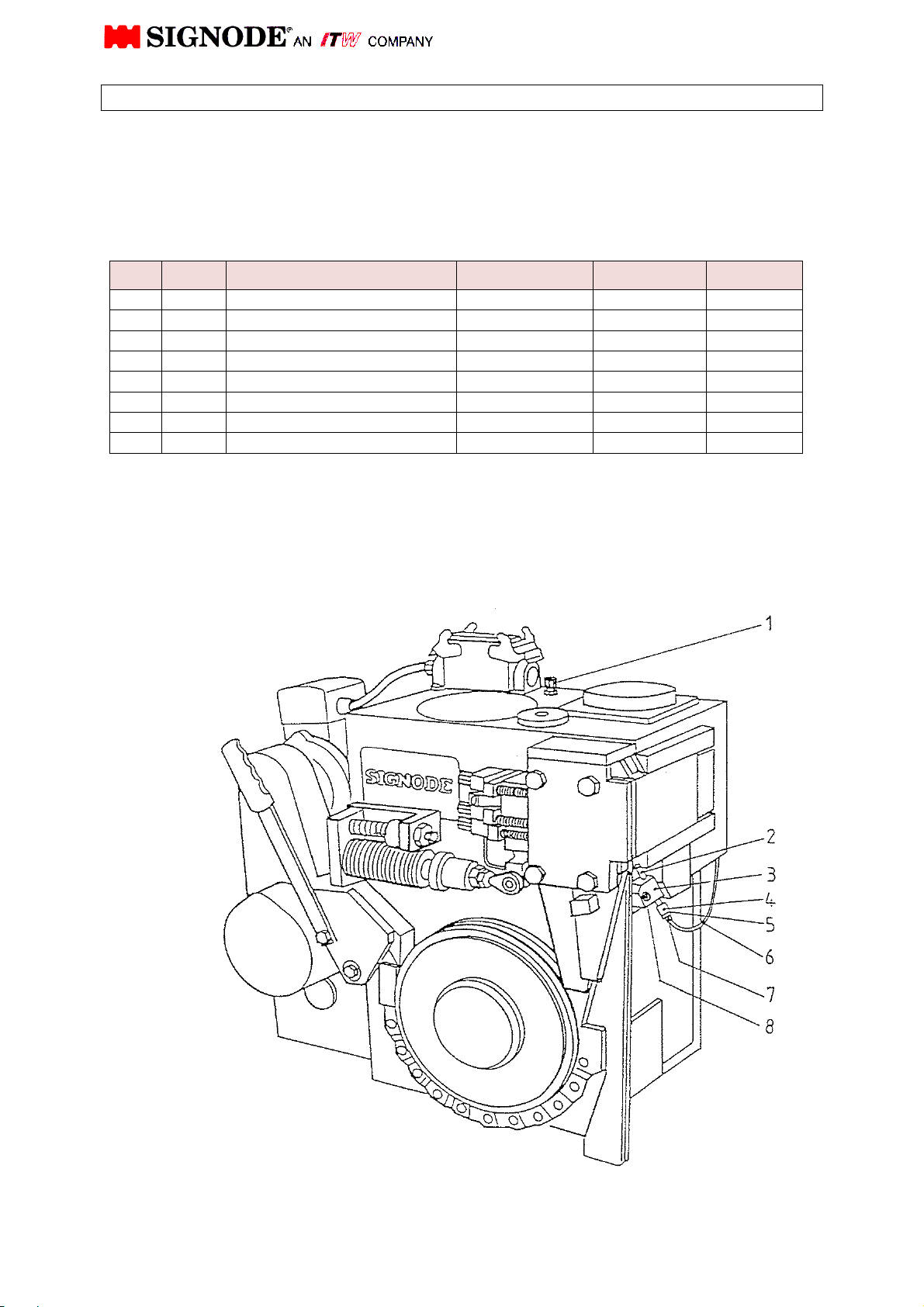
Pos.
Qty.
Description
Draw
ing N°.
DIN/Version
Part N°
.
PARTS LIST
Description: Air blowing device
Drawing N°: 464263
Version/Part N°: 464269
1
1 Fitting SCK600-K 460279
2
1 Tube 462934
3
1 Mounting for tube 462933
4
1 Sleeve 1/8“ 464401
5
1 Seal ring KF 18 1/8“ 460190
6
1 Plastic hose PL-600, 750 lg. 460256
7
1 Quick connection CK-1/8 PK6 460299
8
1 Soc. Head cap srew M6x20 912 0WT0841
64
Page 80
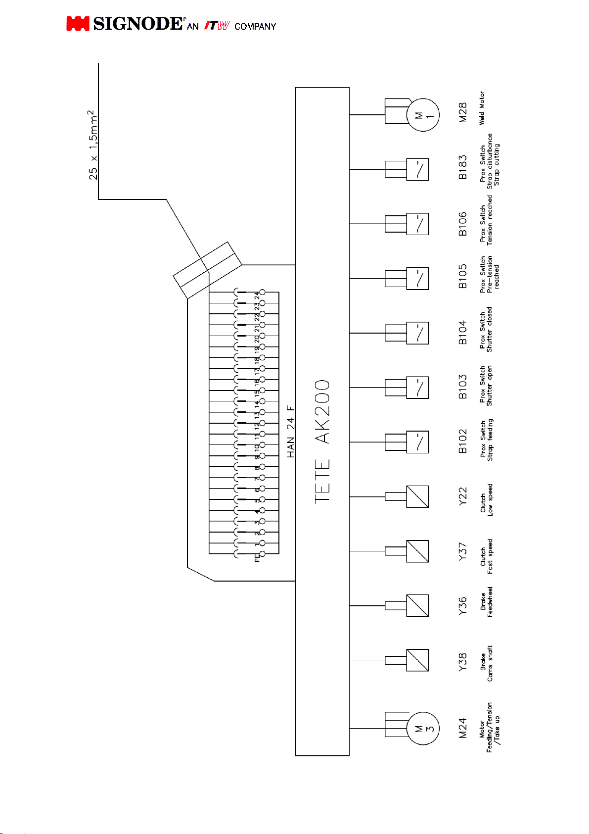
65
Page 81
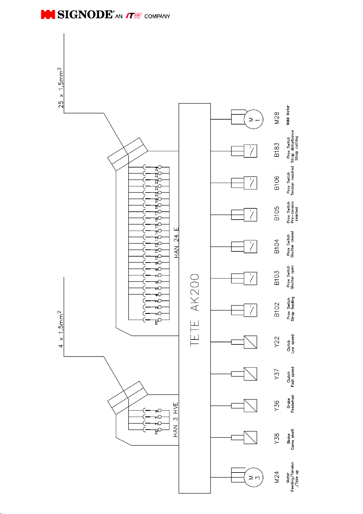
66
Page 82

Rev.
Date
Name
Description
04
03 2011/03/28 Furtm. Page. 42/ Pos. 63 Nr. 464230 Nr.464659 ( M. Funck )
02 2010/09/02 JMM Up dated all pages and page 31 + Pos.9
01 2010/08/24 Hunecken Page 2,8,13,28,29,30,31,34,38,42,47,48,54+56
00 2009/01/29 Supper Original Version
67
 Loading...