

Signode AK200HDX-19, AK200HDX-32, AK200HDX-25 Operation, Parts And Safety Manual
PLASTIC STRAPPING HEAD
MODEL AK200HDX-19 / 25 / 32 mm
Serial N° 09/2008 SN3627
As at : 28 March 2011
It is the customer’s reponsibility to have all
operators and servicemen read and understand
Contact your local Signode representative for
IMPORTANT!
DO NOT DESTROY
this manual.
additional copies of this manual.
OPERATION, PARTS AND SAFETY MANUAL
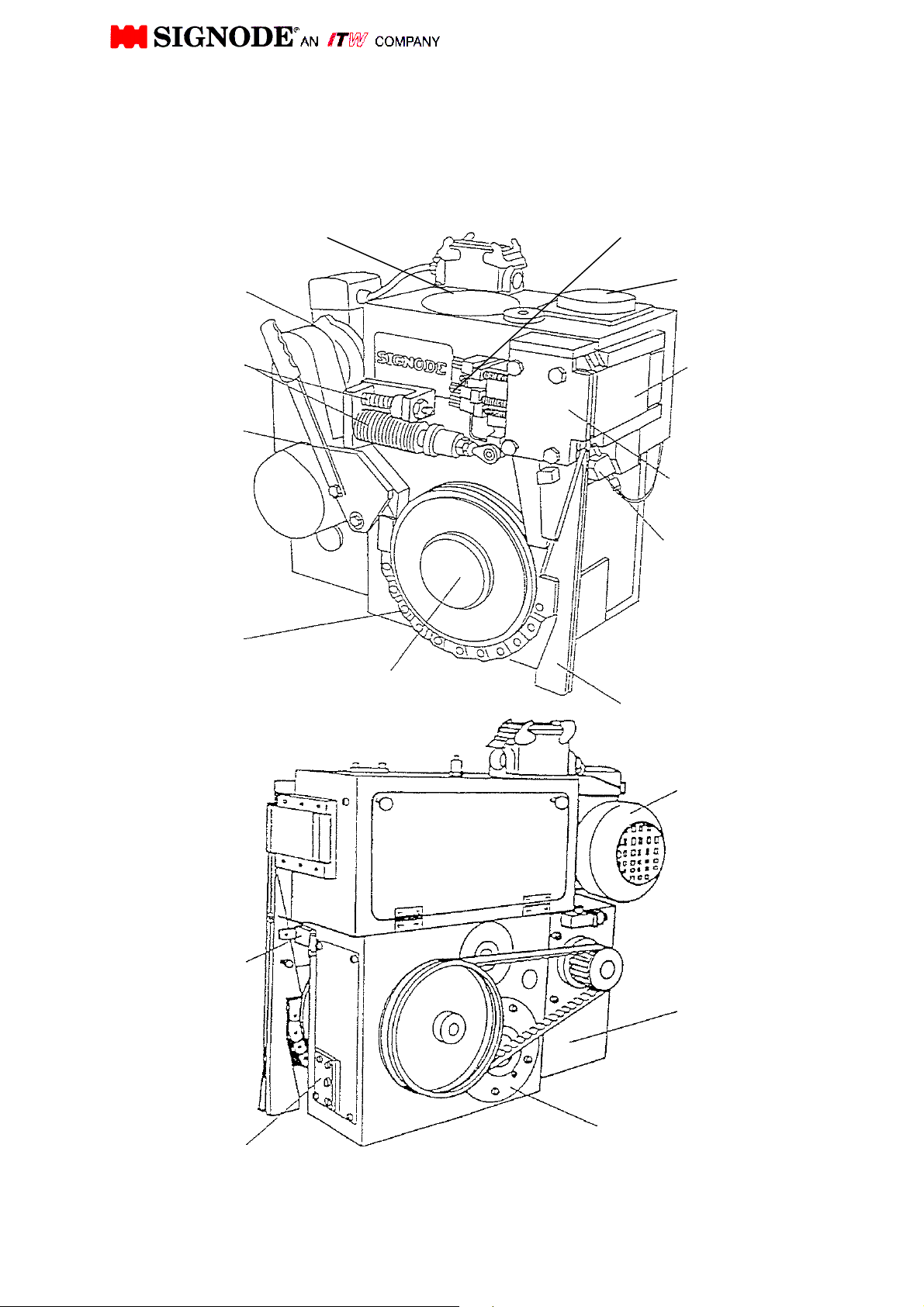
Air blowing
SIGNODE AK200-HDX
Basic Operating and Adjustment Instructions
Drive motor
Disk washer
with aux. spring
Strap entry chute
Back-up
roller chain
Strap stop
switch
Holding brake
cam shaft
Cam shaft
Feed wheel
Sealing punch polder
Weld Motor
Pusher
(cover plate)
Sealing
Mechanism
device
Strap guide wedge
Drive motor
Transmission
Drive motor
1
4.
1.
Keep your Operation, Service and Safety
ADDITIONAL SAFETY INSTRUCTIONS ARE LOCATED THROUGHOUT THIS
GENERAL SAFETY
This manual gives you information on how to operate and maintain your Signode Power
Strapping Machine.
Only trained personnel should operate or service machine.
Read these safety instructions before operating or servicing your machine.
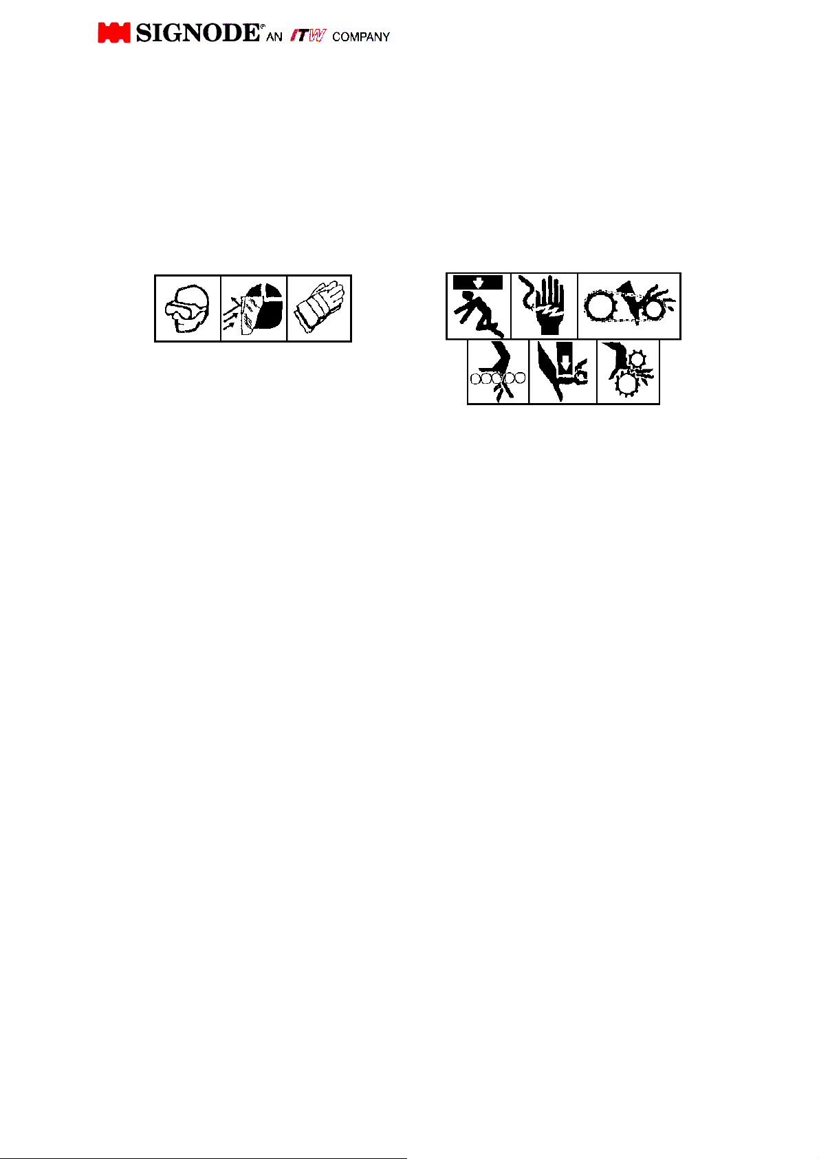
OPERATING MACHINE
BEFORE
1.
Read the operating instructions.
2.
Wear eye or face, and hand protection.
3.
Inspect the machine for unsafe conditions
DAILY and replace any worn or broken
parts.
Check that all guards are in place and all
safety devices are working properly. Do not
operate machine with any safety devices
removed.
5.
Make sure machine is clear of all tools, debris
and other objects not related to machine
function.
DURING
1.
Do not wear loose clothing or jewelry.
2.
Never put any part of your body into, under or
near moving machinery.
3.
Keep hands out of the strap chute area.
AFTER
1.
Shut off all electric an air power.
2.
Remove all tools, debris, and other objects
from machine area.
2.
3.
4.
5.
6.
ADDITIONAL CONSIDERATIONS
To insure proper operation of machine,
Do not overload machine by exceeding
SERVICING MACHINE
Shut off and lock out electric and air
power.
Remove packages from machine.
Do not stand or walk on conveyor service
machine.
Follow the maintenance instructions in
your manual.
Use the correct tools to repair machine.
Never adjust, repair or oil moving
machinery.
use the specified electric and/or air
power sources.
Signode's recommended performance
limitations.
Do not attempt to after machine design
unless written approval is received from
Signode Corporation.
Manual at your machine. Refer to it -
often.
Read all of the signs on
machine.
Do not remove any
signs from machine
Replace all missing or
damaged signs.
MANUAL. THEY SERVE TO WARN THE OPERATOR AND SERVICEMAN
ABOUT POTENTIALLY HAZARDOUS SITUATIONS.
2
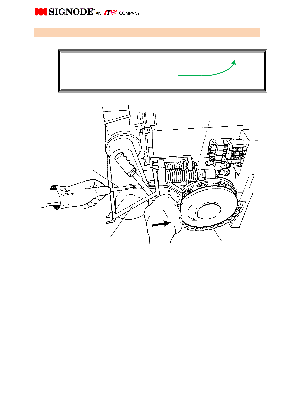
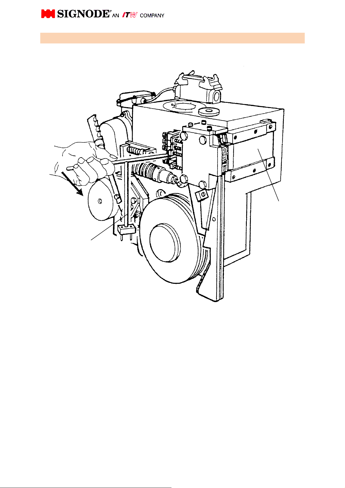
Important Caution!
1. Insert strap
To prevent strap jams natural strap curl
in the direction shown (with the curl up)!
Disk Washers
Strap
Cam Shaft Wrench
Part No. 0460605
Back-up roller Chain
Release tension of the back-up roller chain by compressing the stack of disk washers
with the cam shaft wrench.
Push the strap into the strap guide channel until it meets resistance, then insert strap
into the head using operating mode.
Wear gloves!
3
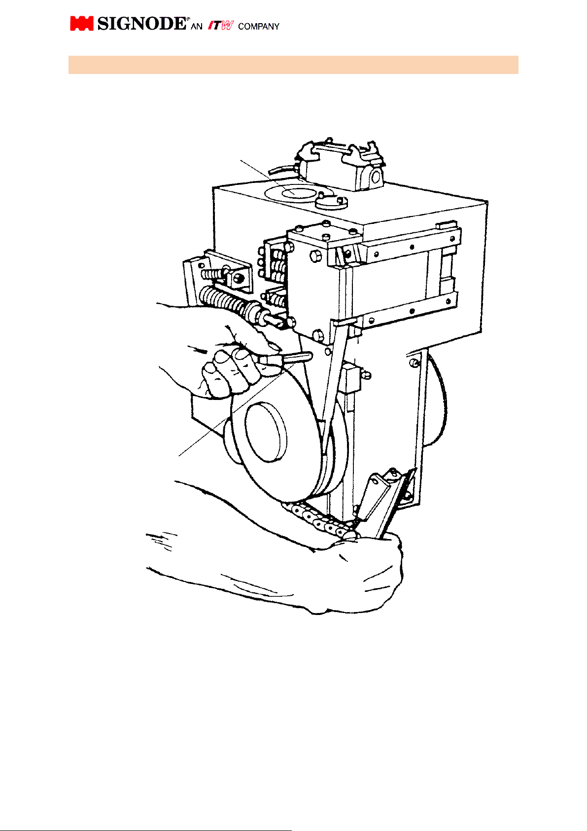
Part No.: 0460605
(cover plate)
2. Opening of pusher (by hand)
Cam shaft wrench
Insert the camshaft wrench into the hole at the end of the pusher lever and move it
towards the right.
The pusher opens and exposes the die holder and vibrator for inspection and
cleaning.
Pusher
4
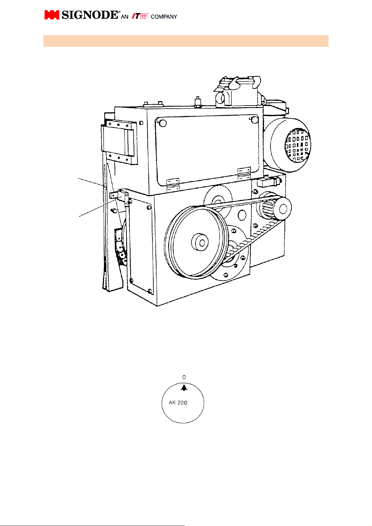
3. Disengage back-up roller chain
To clean the strap guide channel, to remove pieces of strap and to turn the cam shaft
by hand, the back-up roller chain must be disengaged.
First of all, release the back-up roller chain and pull out the pin.
Then disengage the complete chute wedge with the chain.
Pin
Cam shaft
5
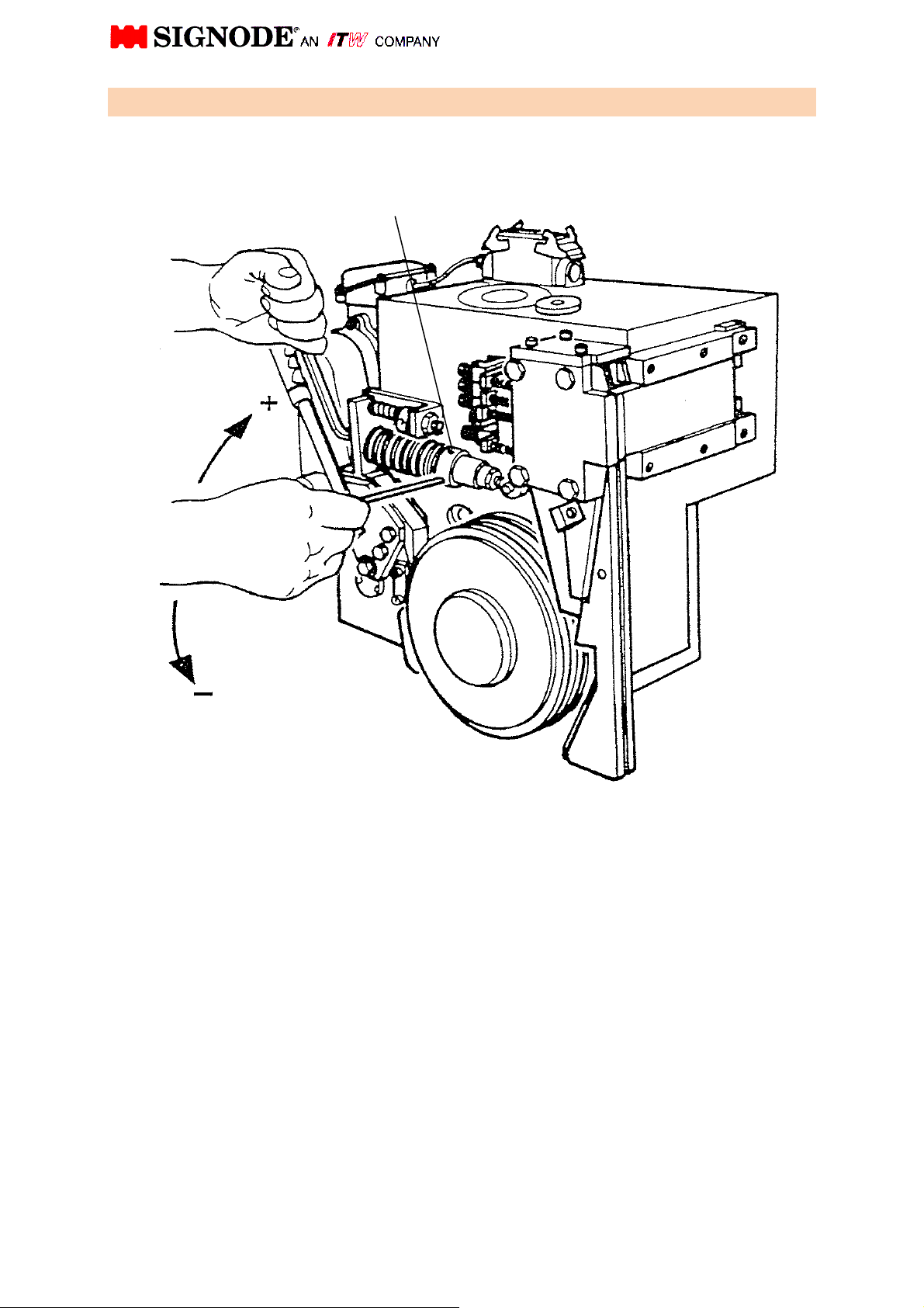
Adjustment screw
4. Strap tension adjustment
Strap tension is increased by turning the adjustment screw clockwise and decreased
by turning it counter-clockwise.
If an extreme low strap tension is desired, you may reduce the disk washers and add
on compression spring. Refer to your instruction manual under chapter "disk washer".
(Drawing-No. 100.07 soft)
6
5 Function of the Proximity switch (strap Stop switch)
Switch actuator
B102 Proximity Switch
“strap stop
With no strap present, the strap Stop switch is not actuated.
Strap passing the switch actuator pushes the same down, energizing the proximity
switch (B102 Strap stop Proximity switch)
”
Cam shaft position: 0
7
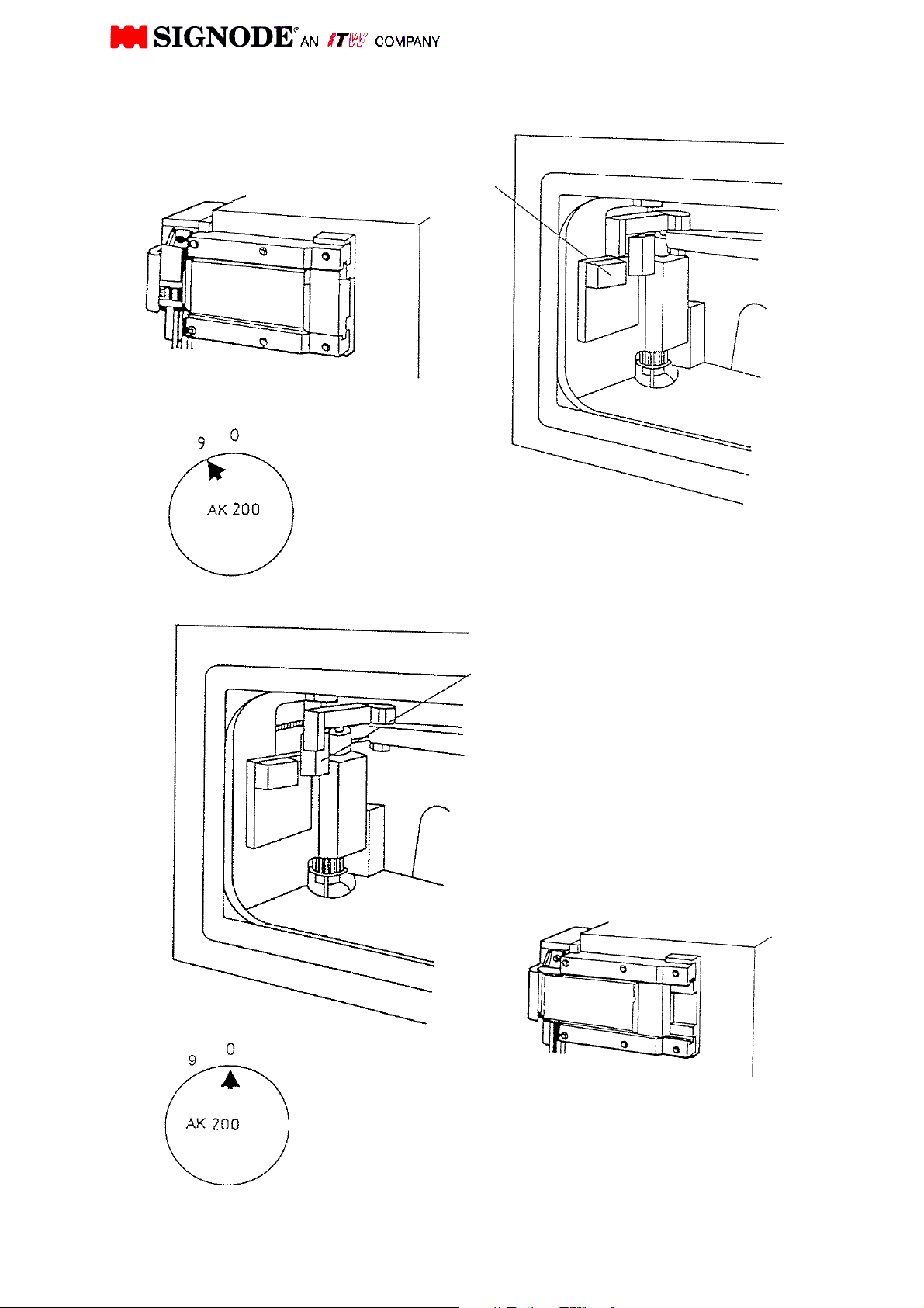
5.1 Function of proximity switch B103 & B104 “ pusher open / closed”
B103 Proximity switch "pusher
open"
Energized (diode lit)
Pusher fully open
Cam shaft position: 9
B104 Proximity switch "pusher
closed"
Energized (diode lit)
Pusher closed
Cam shaft position: 0
8
before 2
slow tension
behind 2
"Pre
-
Tension reached"
"Pre
-
Tension reached"
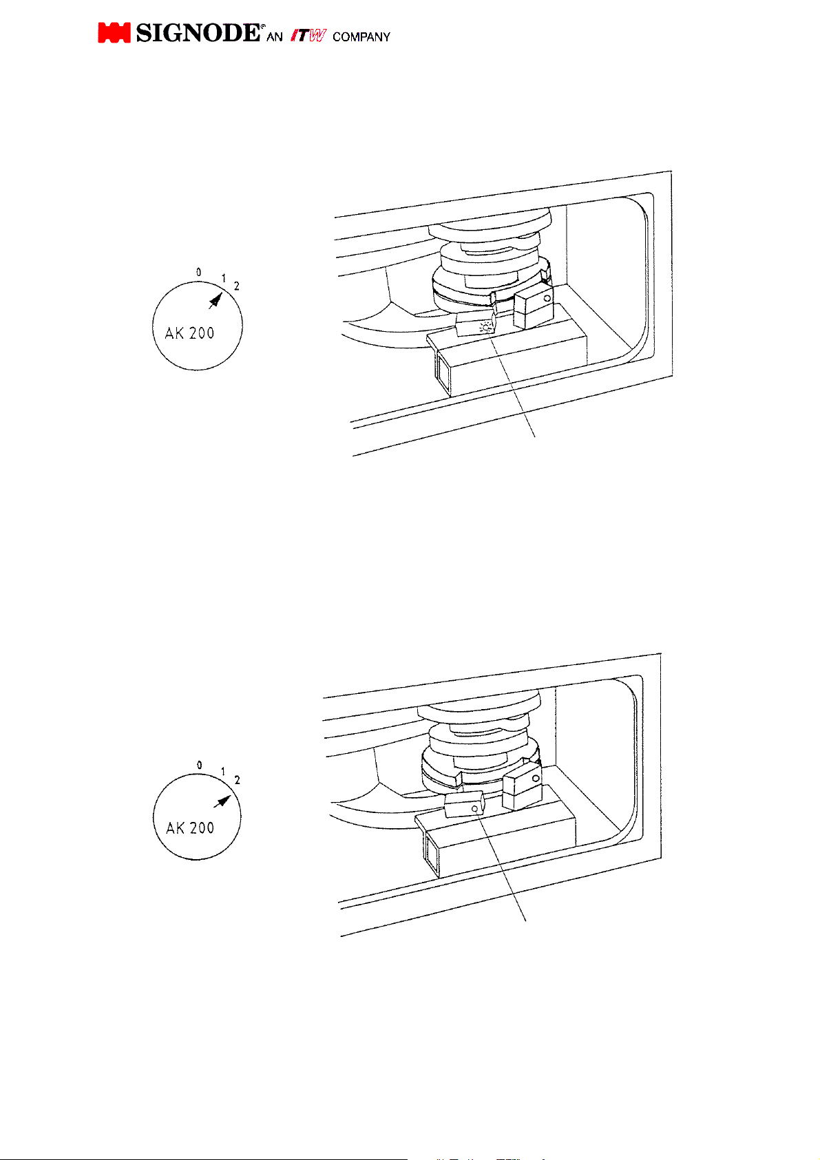
5.2 Function of proximity switch B105
switching from high speed to slow speed tension
Switching energized =
high speed tensioning
(diode lit)
Cam shaft position:
Not energized =
Cam shaft position:
B105 Proximity switch
B105 Proximity switch
9
"Final
-
tension reached"
"Final
-
tension reached
"
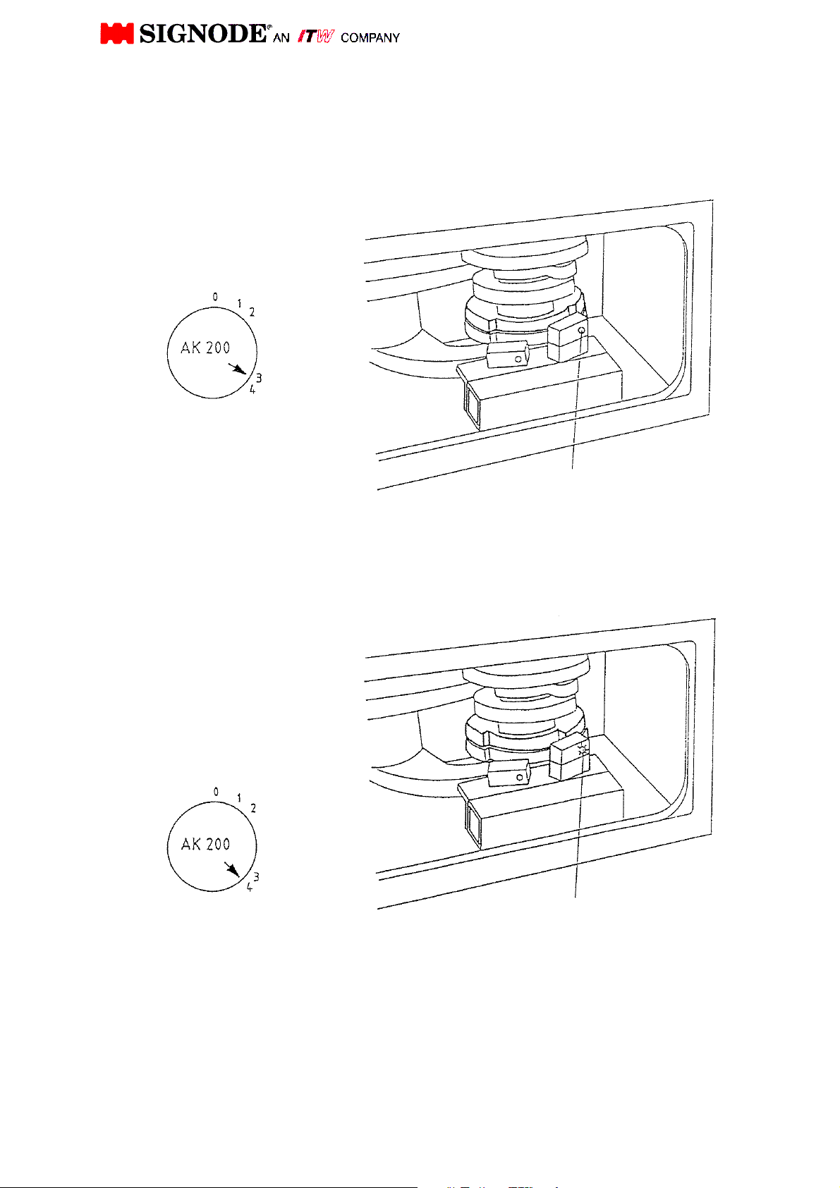
Strap tension is
5.3 Function of proximity switch B106
switch for brake "final tension reached"
Not energized =
strap is being
tensioned (slow)
Cam shaft position: at 3
Energized (diode lit) =
Cam shaft position: at
B106 Proximity Switch
B106 Proximity switch
10
TENSION AND SEALING PROCEDURE
0. Home position proximity switch B104 "shutter close" activated. Shutter closed.
1. Tip of strap is clamped. Proximity switch B106 "max. strap tension reached" will
be activated for the first time.
2. Proximity switch B105 "Pre- tension reached" will be free Switching into tension
slow speed.
3. Strap will be tensioned. Proximity switch B106 "max. strap tension reached" will
be de-activated again.
4. Maximal strap tension reached, cam follower is on highest point of cam. The
spring package is pressed together to its maximum for maximum pre-set strap
tension. Starting strap end clamped. Proximity switch B106 strap tension
reached will be occupied for the second time. Strap drive brake Y36 will be
connected.
5. Loop grip presses firmly both straps. Tip of strap and strap end clamped.
Proximity switch B105 "Pre-tension reached" will be activated again strap
slacken for cut off at no load starts.
6. Weld motor starts and strap will be cut. Proximity switch B105 "pre-tension
reached" will be free again.
7. Cool off joint. Pressing together both straps at camshaft strap. Proximity switch
B105 "Pre-tension" will be activated for the second time.
8. Vibrator, loop grip and gripper in home position. Proximity switch B104 "Shutter
close" will be free. Shutter starts opening.
9. Proximity switch B103 "Shutter open" is occupied and proximity switch B105
"pre-tension reached" will be free again. Shutter fully opened.
11

SERVICE AND MAINTENANCE MANUAL
FOR STRAPPING HEAD
MODEL
AK200-HDX-19 / 25 / 32 mm

T A B L E O F C O N T E N T S
Section Page
General
Technical Specifications
Sequence of Operation
Positions on Camshaft Display
Preventive Maintenance
Parts Removal and Replacement
Head Adjustments
Trouble Shooting
Recommended Spare Parts List
Remote Spare Parts List
Conversion Kit AK200-
Sub-Assembly Drawings & Parts List
HDX auf 32 mm / 25 mm / 19 mm
464631 Version 32 mm
Strapping Head
464624 Version 25 mm
464618 Version 19 mm
1 1
2 2
3 3
4 10
5 13
6 14
7 17
8 20
9 25
10 28
31
11 32
33
464655 Version 32 mm
Sealing Mechanism
464656 Version 25 mm
39
464657 Version 19 mm
Transmission - 15 -
Strap Drive
Brake
Intermediate Shaft
Camshaft
"Camshaft Brake"
Spring Assembly
Insert Guide with Spring
Strap Guide Wedge
Air Blowing Device
100.36 43
464626 47
100.14 50
464291 52
464613 54
150.15 56
100.07 58
464643 60
464636 62
464269 64
Electrical Plans
Installation
1 Plug Wiring 65
Option:
2 Plugs Wiring 66

1. GENERAL
The SIGNODE AK200 Plastic Strapping Head is designed to be used for applying various
qualities of plastic strapping fully automatically.
The head is only part of the strapping installation, which consists of the main structure, chute
system and control panel.
In order to ensure trouble free operation it is important that all operation and maintenance
personnel have received adequate instruction about the operating sequence of the head.
Furthermore, it is important that all will be familiar with the operation and maintenance manual
as supplied with the strapping head.
When operating and maintaining the head, it is important to regard all safety regulations valid in
the country of operation and supplied by the appropriate safety board or organization.
NOTE:
Before starting the head, check feeding direction of strap drive.
For a long lifetime of the feed wheel ring, it is important that the feed wheel ring does not run
without strap during strap threading. The strap feed control time depends on the strap chute
size and must be set as short as possible (max. 0.5 sec longer as necessary to fill up the strap
chute).
The tension control time must always be set shorter than the overall feeding time so that the
strap cannot escape out of the head, and that always strap rests between feed wheel ring and
roller chain, see adjustments of roller chain 7.6 , page 19.
1

2. TECHNICAL SPECIFICATIONS AK200-HDX
Strapping Width: 32 mm; 25 mm; 19 mm
Strap Thickness: 0,5 - 1,3 mm
Joint Strength: Depends on individual strap
size and strap quality
Feed and Take Up Rate: 1,25 m/sec. (high)
0,07 m/sec. (slow)
Tension: max. 6000 N / adjustable
Min. Package Face: approx. 150 mm
Joint Time: approx. 4,5 seconds
incl. 2 sec. cool-off time
Weight: 95 kg
Power Source: 400 V, 3 Ph, 50 Hz
CAUTION! In case of different motor connection!
(for USA 270 / 480 V, 3 Ph, 60 Hz)
Control Voltage: 24 V
Weld Motor: 230 V, 50/60 Hz
2

3. SEQUENCE OF OPERATION
3.1 GENERAL
The SIGNODE AK200-HDX is electrically powered and electrically / electronically controlled.
Only one power source is needed to operate the head.
The sequence of operation consists of two major functions. These are:
- First "Strap Feeding"
- Second "Strap Take up", "Strap Tension", "Strap Sealing"
Both functions can be operated on the control panel manually by inching push button.
In addition the function "Shutter Open/Closed" can also be operated manually by inching push
button.
Because of the high resistance from the tension cam it is not possible
to turn the camshaft by hand.
If it necessary to turn the camshaft by hand. Please disconnect first the
strap guide chain.
Remove the release pin (see Rep.58, figure 0464631, page 33) and
swing strap guide wedge inclusive chain (see Rep.10, figure 0464631,
page 33) backwards.
Also please swing out the stop device by pull off the catch pin
(voir Rep.14 + 15, figure 0464643, page 60)
3
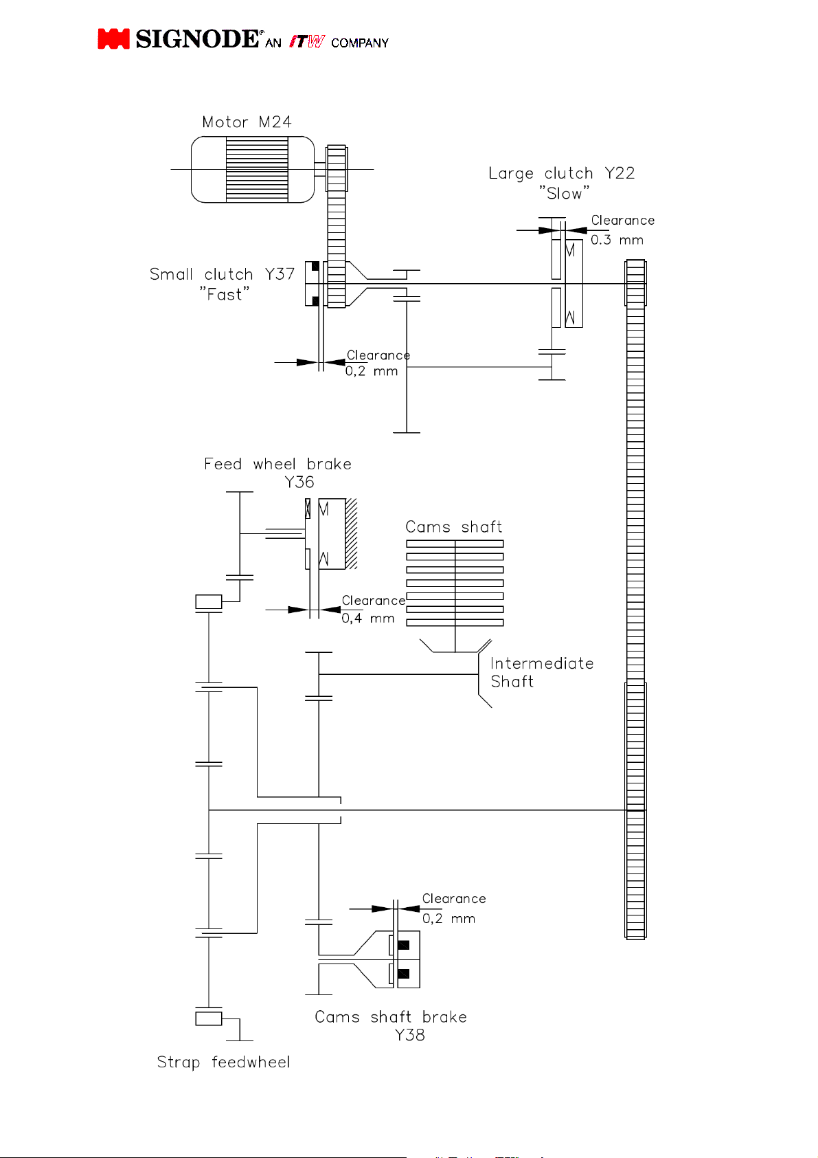
Strapping head drive (allegory)
4

3.2 Table of contents
M 24 = Motor
M 28 = Weld Motor
Y 37 =
Y 22 =
Y 36 =
Y 38 =
Small clutch 15 Nm ,
« transmission Fast »
Large clutch 60 Nm
« Transmission Slow »
Electro-Magnetic Brake
"Strap Drive"
Electro-magnet brake
«Camshaft»
See drawing
464631, Rep. 82
See drawing
464631, Rep.83
B102 =
B103 =
B104 =
B105 =
B106 =
B183 =
Proximity Switch
«Strap stop» (Strap Feed Stop)
Proximity Switch
« Shutter open»
Proximity Switch
« Shutter close »
Proximity Switch
« Pre-tension reached »
Proximity Switch
« Final Tension reached »
Proximity Switch
« Strap Disturbance and Strap cutting at no load »
See drawing :
464631, Rep. 76
See drawing :
464631, Rep. 77
See drawing :
464631, Rep. 78
See drawing :
464631, Rep. 79
See drawing :
464631, Rep. 80
See drawing:
464631, Rep. 81
5

3.3 Operation Description
(See section 4, simplified view)
The strapping head is in home position. The camshaft display indicator is on - 0 - position, and
the camshaft is blocked against rotation in anti-clockwise direction further than the - 0 - position
on the camshaft display. The switch B104 is activated, indicating that the shutter is closed.
With start of the strap cycle program, strap feeding will be initiated. While strap feeding the
motor M24 (see drwg. 464631, pos. 82, page 33) is running in clockwise direction. The small
clutch Y37 "high speed" (see drwg. 100.36, pos. 41, Page 43) of the transmission is activated
and the strap is fed through the chute system at high speed.
On re-entry of the strap into the head, the limit switch B102 positioned in the strap guide wedge
will be activated (see drwg. 464631, pos. 76, page 33). The activated strap feed switch initiates
the large clutch Y22 after a delayed time, causing the motor M24 to interrupt feeding after a
certain time, depending on the setting of the time relay. This setting directly influences the strap
overlap length. During strap feed the camshaft brake Y38 is energised.
Next step; strap being clamped, will be initiated. The motor changes into counter clockwise
direction, at the same time the strap drive brake Y36 will be activated and the "camshaft brake"
Y38 is de-energised. The large clutch Y22 will be activated and the camshaft rotates in
clockwise direction from position 0 into position 1. The proximity switch B106 "max strap tension
reached" will be activated for the first time. The camshaft stops at position 1 and the tip of the
strap will be clamped by the gripper (see drwg. 464655, pos. 8, page 39). Camshaft brake Y38
will be activated again. The strap drive brake Y36 will be de-activated.
6

Next step; strap tension will be initiated. The camshaft brake Y38 will now be activated and the
brake Y36 is de-energised. The large clutch Y22 in the transmission is de-energised and the
small clutch Y37 will be activated. The strap drive changes rotation at high speed and the strap
is pulled out of the strap chute system and is applied around the package (during high tension
the camshaft brake Y38 will be de-energised after a certain delayed time).
When the strap has been applied to the package, the strap drive is slowed down by the strap
being tensioned and the function of the planetary gear shaft rotates the camshaft from position 1
into point 2. Hereby the camshaft has to overcome the spring pressure of the pre-tension spring
(see drwg. 100.07, pos. 17, page 58).
At point 2 the sensor "Pre-tension reached" (switching fast -slow) will be free. The diode does
not gleam anymore (see drwg. 464631, pos. 79, page 33). Therefore the small clutch Y37 is de-
energised and the large clutch Y22 is activated. The transmission is now running at slow speed.
Depend on the adjusted spring resistance for the max. strap tension the camshaft rotation will
be retarded. The strap drive rotates now at slow speed until the strap drive will be stopped by
the raising strap tension and the camshaft rotates from point 3 into point 4.
Because of the planetary gear drive function and depending on the raising strap tension and
raising resistance due to the risk of the cam disc a relative moment between the strap drive and
camshaft occurs, until the adjusted max. strap tension on camshaft point 4 has been reached.
At camshaft point 4 the sensor "Strap tension reached" will be activated for the second time
(diode lit). The brake Y36 will be activated and blocks the strap drive via the gears in position 4.
The tensioned strap will now be held by the strap drive. The camshaft rotates from point 4 into
position 5. In position 5 the strap end (loop) will be fully clamped by the loop grip (see drwg.
464655, pos. 7, Page 39). The sensor "Pre-tension reached" will be activated again.
With this switch point the camshaft brake Y38 will be activated and the motor M24 and the large
clutch Y22 will be de-energised.
Also the brake Y36 for strap drive will be de-energised after a delayed time (400 ms).
Next step, "strap end cutting at no load" will be initiated. During the strap loosen time "time set in
the program" the strap will be loosen and turned the strap drive for a short time in feeding
direction until the strap is without load.
After the strap loosen time and a additional delay time (500 ms) the strap can cut under no load.
The motor M24 will be energised in tension direction, the large clutch Y22 and strap drive brake
Y36 will be activated and the camshaft brake Y38 will be de-energised again.
7

The camshaft rotates from position 5 to position 7 and the next step, welding will be initiated.
Thereby the vibrator support moves forward with the cutter blade and vibrator.
(see drwg. 464655, pos. 9, 22, 25, Page 39).
At point 6 the sensor "Pre-tension reached" will be de-activated again. With this switching point
the weld motor will be started, and via the eccentric drive of the vibrator the weld oscillation will
be reached. First the cutter blade cuts off the strap end under no load and the vibrator presses
both straps oscillating on top of another. The oscillation process melts both layers of strap
together. Depending on the strap quality the programme sequence is set (approx. 0, 5 sec) and
the weld motor stops. The strap ends will be combined by the motionless vibrator. At position 7
the camshaft stops as long as the cool off time is set in the programme sequence
(approx. 3 sec.), so the melted joint is able to cool off under pressure.
8

After the cool off time has expired, strap release will be initiated. The camshaft rotates from
position 7 into point 8. Gripper, loop grip and vibrator move backwards to its home point 8.
The camshaft rotates from point 8 without stopping into position 9. The shutter starts opening
(sensor "Shutter close" will be de-activated) and is in fully open position at position 9 (sensor
"Shutter open" is occupied and sensor “Pre-tension reached” will be de-activated again). The
"Camshaft brake" Y38 will be activated and holds the camshaft in position until next step
"Shutter close" will be activated. At the same time the large clutch Y22 ("slow speed") de-
energises and the motor M24 rotates in idle position.
At this point, the head is moved away from the package, releasing the strap from the sealing
mechanism until limit switch "Head back to home position" (machine installation) is activated.
Next step; "Shutter close" is activated. The camshaft rotates now from position 9 into position 0.
Hereby the "strap drive brake" Y36 is activated and the camshaft brake Y38 de-activated. At the
same time the large clutch Y22 is activated.
Before reaching position 0, the sensor "Strap tension reached" will be de-activated again and
that time the large clutch Y22, motor M24 and the strap drive brake Y36 have to be deactivated.
The camshaft brake Y38 has to be activated and stops the camshaft in position 0. The camshaft
rests in position 0 and the shutter is closed. Is the sensor “shutter close” activated also, the
head is in home position and ready for further application.
This procedure is for AK200-HDX
AK200 standard head is different.
Note:
See sequence of operation for exact time schedules. Any manual adjustment in the operational
sequence shall be done by skilled personnel only.
9

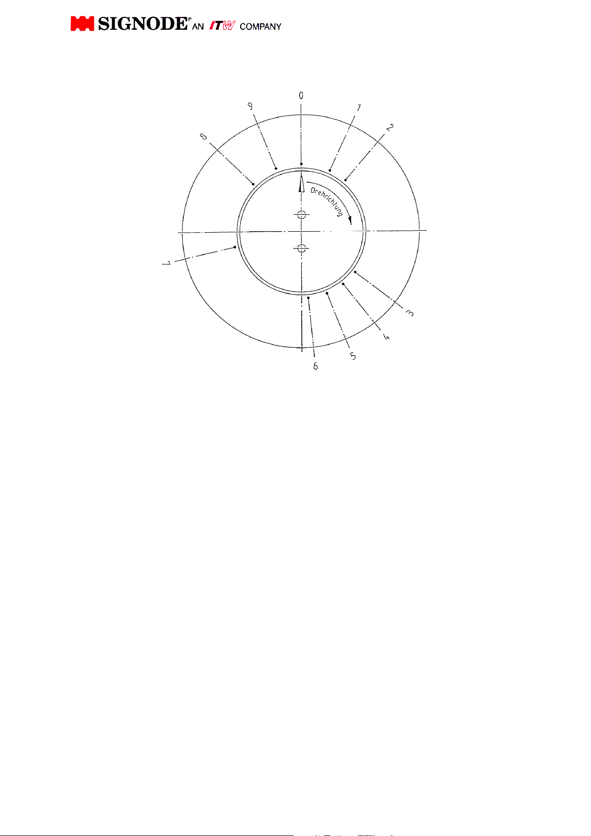
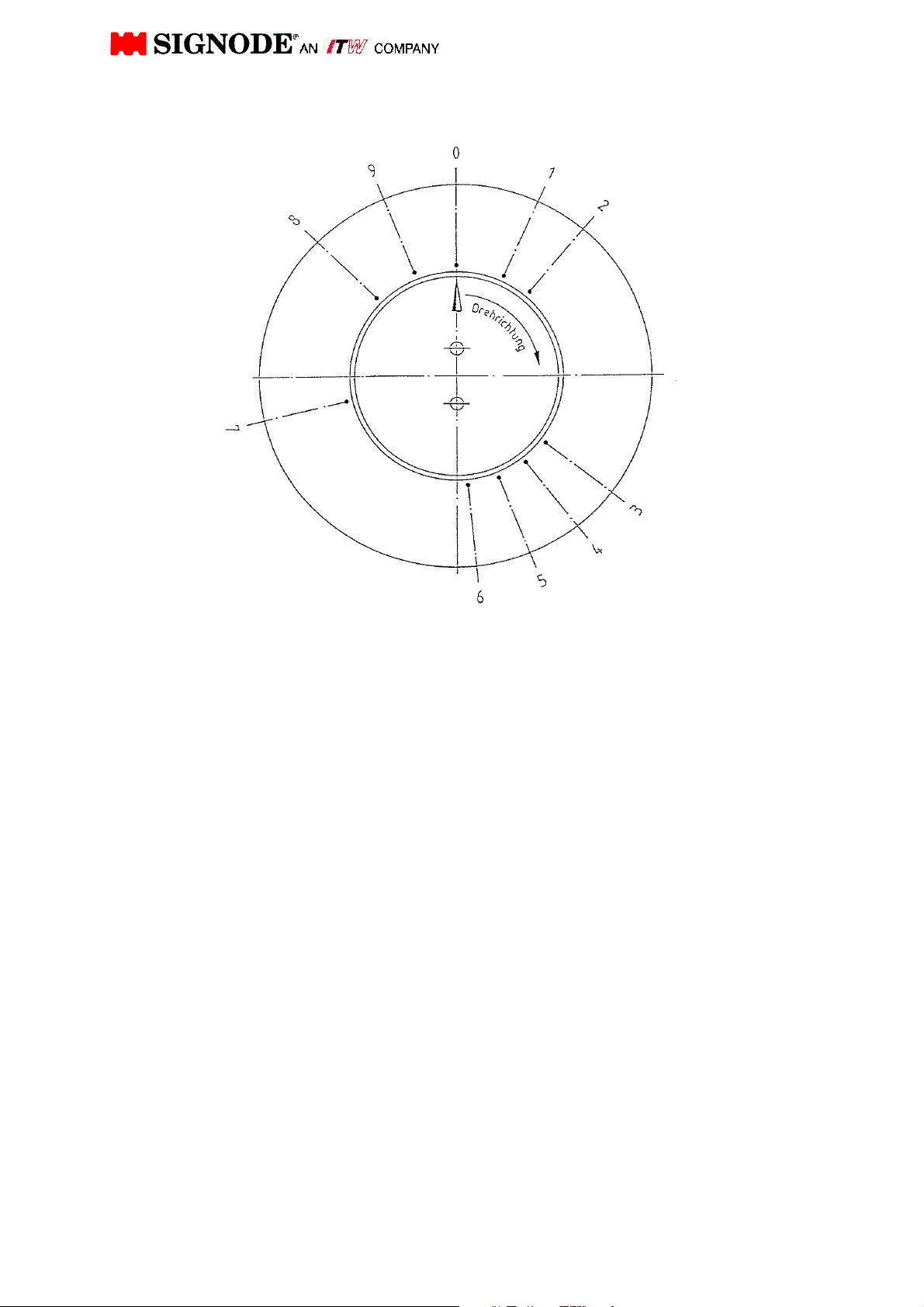
4. POSITIONS ON THE CAMSHAFT DISPLAY
Position 0: The strapping head is in home position. Camshaft brake Y38 holds the
camshaft (time controlled) in position 0. The camshaft is blocked against
turning in counter-clockwise direction further than 0 position via a freewheel.
The proximity switch "Shutter Close" is activated. During strap feed the
camshaft brake Y38 is energised.
Position 1: "Tip of strap is clamped". Proximity switch "max. strap tension reached" will
be activated for the first time. The feed motor rotates in counter-clockwise
direction and the take-up cycle is started at high speed. During high tension
the camshaft brake Y38 will be de-energised after a delayed time.
Position 2: Proximity switch "Pre-tension reached" will be free. Shifting from "High speed"
to "Low speed" is activated.
Position 3: Strap will be tensioned. Sensor “max. strap tension reached” will be de-
activated again.
Position 4: Max. strap tension is reached. The cam follower is at highest point of cam
200.7 The camshaft is blocked by the freewheel so the camshaft has no
chance to rotate in counter-clockwise direction. The spring package is
pressed together to its maximum for the max. pre-set strap tension. The
sensor "max. strap tension reached" will be activated for the second time. The
brake Y36 will be activated.
Position 5: Loop grip presses firmly both straps (tip of strap and strap end clamped).
Proximity switch "Pre-tension reached" will be activated again. Hereby strap
slacken (strap at no load) is activated.
Position 6: The vibrator and cutter blade move forward. The strap will be cut off at no
load. The sensor "Pre-tension reached" will be de-activated again. With this
switching point the weld motor starts and both strap ends are welded.
Position 7 Proximity switch "Pre-tension reached" will be activated for the second time
The camshaft stops as long as the cool off time is set in the programme
sequence.
Position 8: Vibrator, loop grip and gripper return into home position. Pusher starts
opening.
Position 9: Pusher is fully opened sensor " Shutter open" is occupied and sensor “Pre-
tension reached” will be de-activated again, the joint moves out of the
mechanism. Camshaft brake Y38 is activated and blocks the camshaft until
next step "Shutter close" will be activated.
Position 0: The sensor "strap tension reached" will be de-activated again and sensor
“Shutter close” will be activated, the camshaft brake will be activated and stops
the camshaft in position 0 and the shutter is closed.
Note: Further description see section 3.3 and camshaft position next page.
10
TENSION- AND SEALING PROCEDURE
0. Home position proximity switch B104 "shutter close" activated. Shutter closed.
1. Tip of strap is clamped. Proximity switch B106 "max. strap tension reached" will
be activated for the first time.
2. Proximity switch B105 "Pre- tension reached" will be free Switching into tension
slow speed.
3. Strap will be tensioned. Proximity switch B106 "max. strap tension reached" will
be de-activated again.
4. Maximal strap tension reached, cam follower is on highest point of cam. The
spring package is pressed together to its maximum for maximum pre-set strap
tension. Starting strap end clamped. Proximity switch B106 strap tension
reached will be occupied for the second time. Strap drive brake Y36 will be
connected.
5. Loop grip presses firmly both straps. Tip of strap and strap end clamped.
Proximity switch B105 "Pre-tension reached" will be activated again strap
slacken for cut off at no load starts.
6. Weld motor starts and strap will be cut. Proximity switch B105 "pre-tension
reached" will be free again.
7. Cool off joint. Pressing together both straps at camshaft strap. Proximity switch
B105 "Pre-tension" will be activated for the second time.
8. Vibrator, loop grip and gripper in home position. Proximity switch B104 "Shutter
close" will be free. Shutter starts opening.
9. Proximity switch B103 "Shutter open" is occupied and proximity switch B105
"pre-tension reached" will be free again. Shutter fully opened.
11
 Loading...