

Page 1
4A1-114/114KR & 4A1-2
MANUAL TENSIONERS
Page 2

READ THESE INSTRUCTIONS CAREFULLY. FAILURE TO FOLLOW THESE INSTRUCTIONS CAN
RESULT IN SEVERE PERSONAL INJURY.
GENERAL SAFETY CONSIDERATIONS
1. TOOL MANUAL
Before using this tool read and understand the operation manual.
2. STRAP BREAKAGE HAZARD
Never position yourself in-line with the strap during tensioning and sealing. Properly position
yourself when tensioning and sealing as shown in the operating instructions.
Improper operation of the tool, sharp corners on the load, improper strap placement around
the load or an unstable or shifted load could result in strap release or breakage, during
tensioning. This could result in the following:
!! A sudden loss of balance causing you to fall.
!! Both tool and strap flying violently towards your face.
3. TRAINING
This tool must not be used by persons not properly trained in its use. Be certain that you
receive proper training from your employer. If you have any questions contact your Signode
Representative.
4. EYE INJURY HAZARD
Failure to wear safety glasses with side shields can result in severe eye injury or
blindness. Always wear safety glasses with side shields which conform to ANSI
Standard Z87.1 or EN 166.
5. FALL HAZARD
Maintaining improper footing and/or balance when operating the tool can cause you to fall.
Do not use the tool when you are in an awkward position.
6. CUT HAZARD
Handling strap or sharp parts could result in cut hands or fingers. Wear
protective gloves.
7. TOOL CARE
Take good care of the tool. Inspect and clean it daily, lubricate it weekly and adjust when
necessary. Replace any worn or broken parts.
8. WORK AREA
Keep work areas uncluttered and well lighted.
2
Page 3
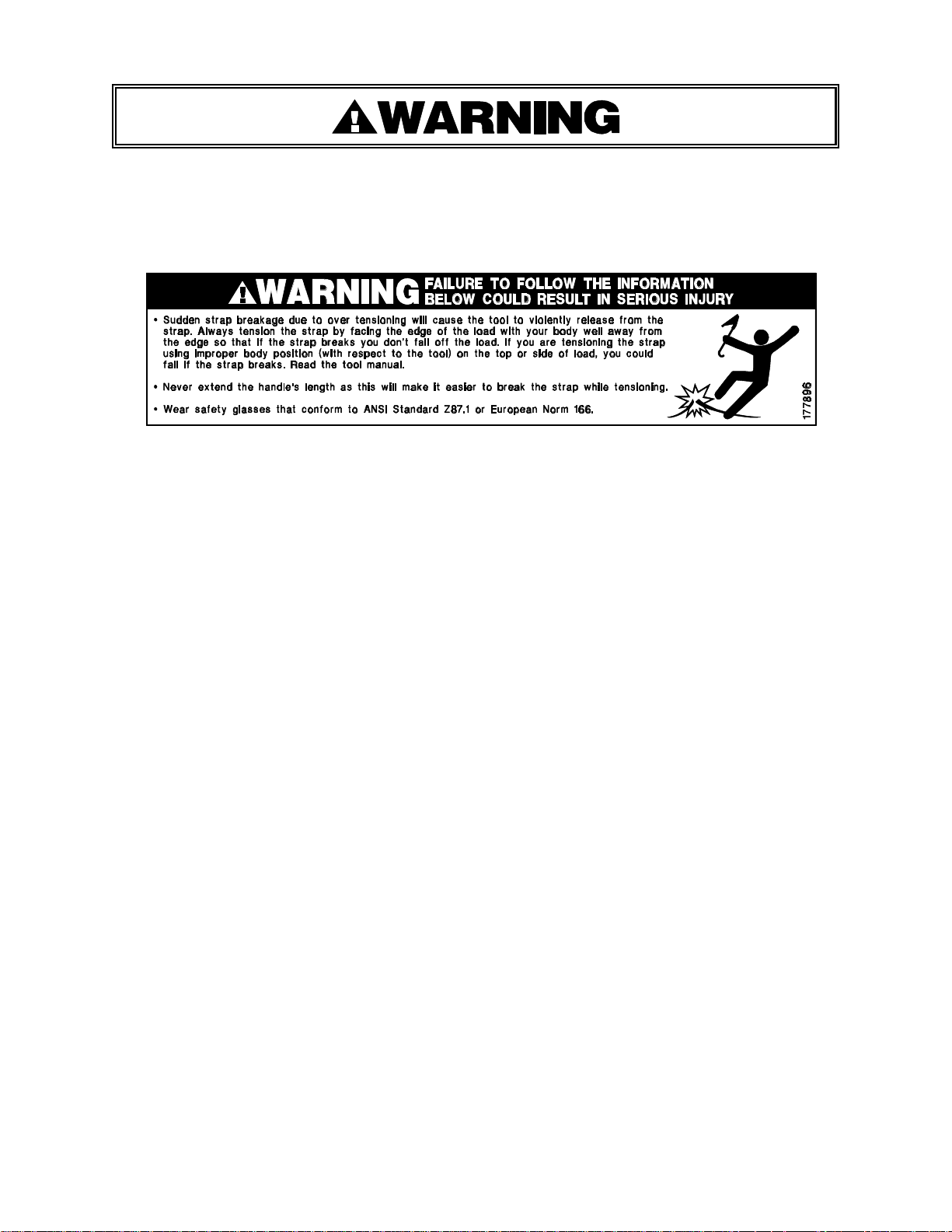
9. WARNING LABEL 177896
The warning label shown below is on the tool handle. If this label becomes damaged, replace
it immediately. Ensure that a plastic shrink tube sleeve us applied over the label. Contact
your Signode Sales Representative if you have any questions.
10. CUTTING TENSIONED STRAP
A. Keep all bystanders at a safe distance, away from the danger zone (shaded area) and
possible flying strap ends.
B. Stand to one side of the strap being cut - outside of the danger zone (shaded area).
C. Cut the strap.
3
Page 4
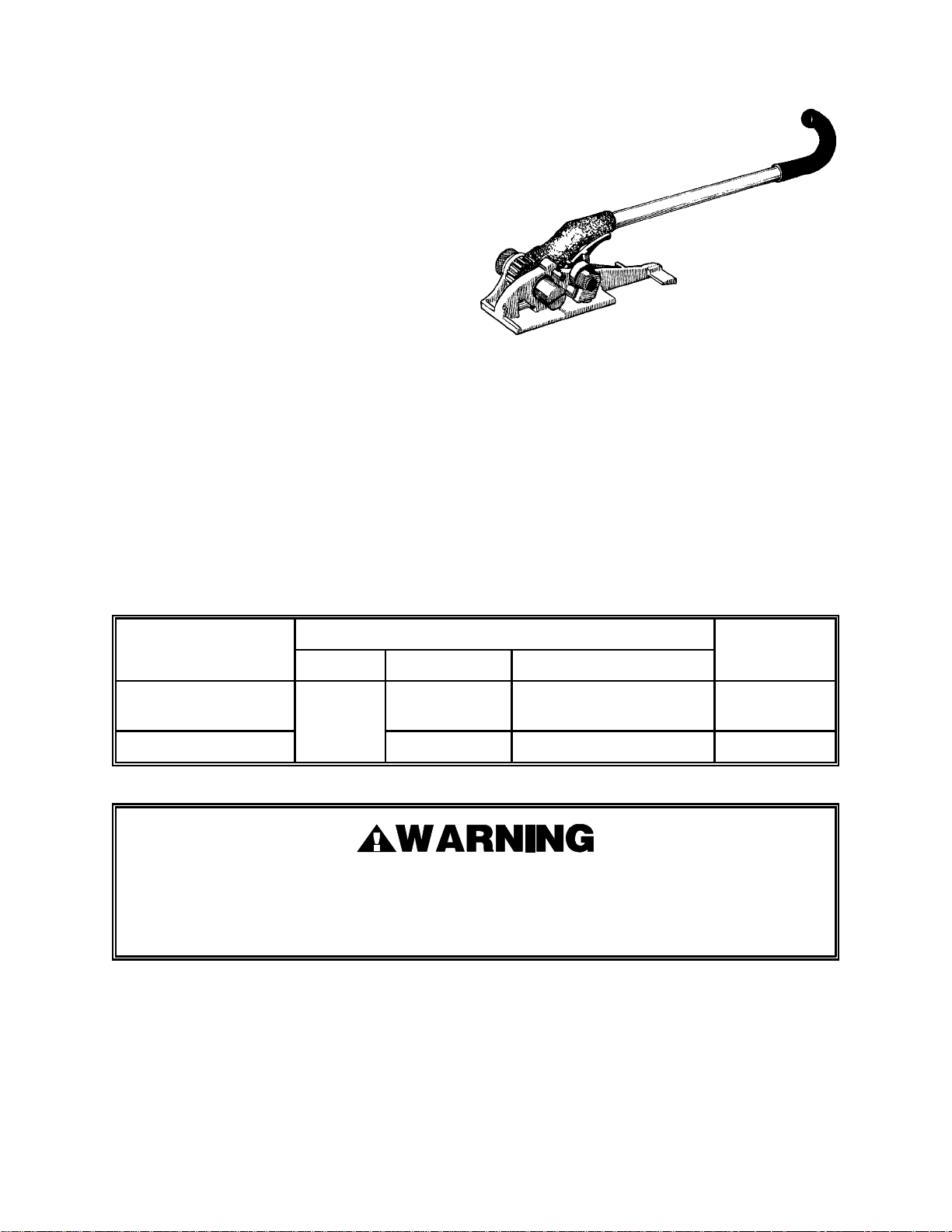
TABLE OF CONTENTS Page
General Safety Instructions 2
Specifications 4
Operating Instructions Overview 5
Placement Around Load 6
Inserting Strap Into Tool 7
Top of Load 8
Side of Load 9
Wall Anchored Load 10
Part Removal & Replacement 12
Troubleshooting 16
Parts List 20
4A1-114, Part No. 184125
4A1-114KR, Part No. 1844135
4A1-2, Part No. 184140
SPECIFICATIONS
STRAP
TOOL MODEL TYPE WIDTH THICKNESS SEALS
4A1-114
4A1-114KR Magnus
4A1-2 2" Min. .044" Min. to .050"
1-1/4" Min. .031" Min. to .050"
With the 4A1-114 and 4A1-114KR tools, use only 1-1/4" wide (minimum) x .031" thick
(minimum) hi tensile strap. With the 4A1-2 tool, use only 2" wide (minimum) x .044" thick
(minimum) hi tensile strap. Failure to use the proper tool or strap can result in serious
injury. Contact your Signode Sales Representative for the correct strap for your application.
4
Page 5
OPERATING INSTRUCTIONS
When tensioning or sealing, position yourself according to the operation instructions for
the type of load being strapped. Keep all bystanders away.
It is recommended that safety belts be worn by operators working on at elevated positions.
Never increase the length of the tensioning handle by any means such as extending the
handle length.
Apply tensions that are proper for the size and type of strap being used and is compatible
with the loads being strapped and its corner characteristics. Contact your Signode Sales
Representative if you have any questions.
Tuck the strap end back into the dispenser when you are not using it.
Operating instructions are broken down into the following sequences:
1. Placing strapping around a load.
2. Inserting strapping into tool.
3. Tensioning strap when on top of a load.
4. Tensioning vertical strap for sides of a load.
5. Tensioning strap for wall anchored load and horizontal strap.
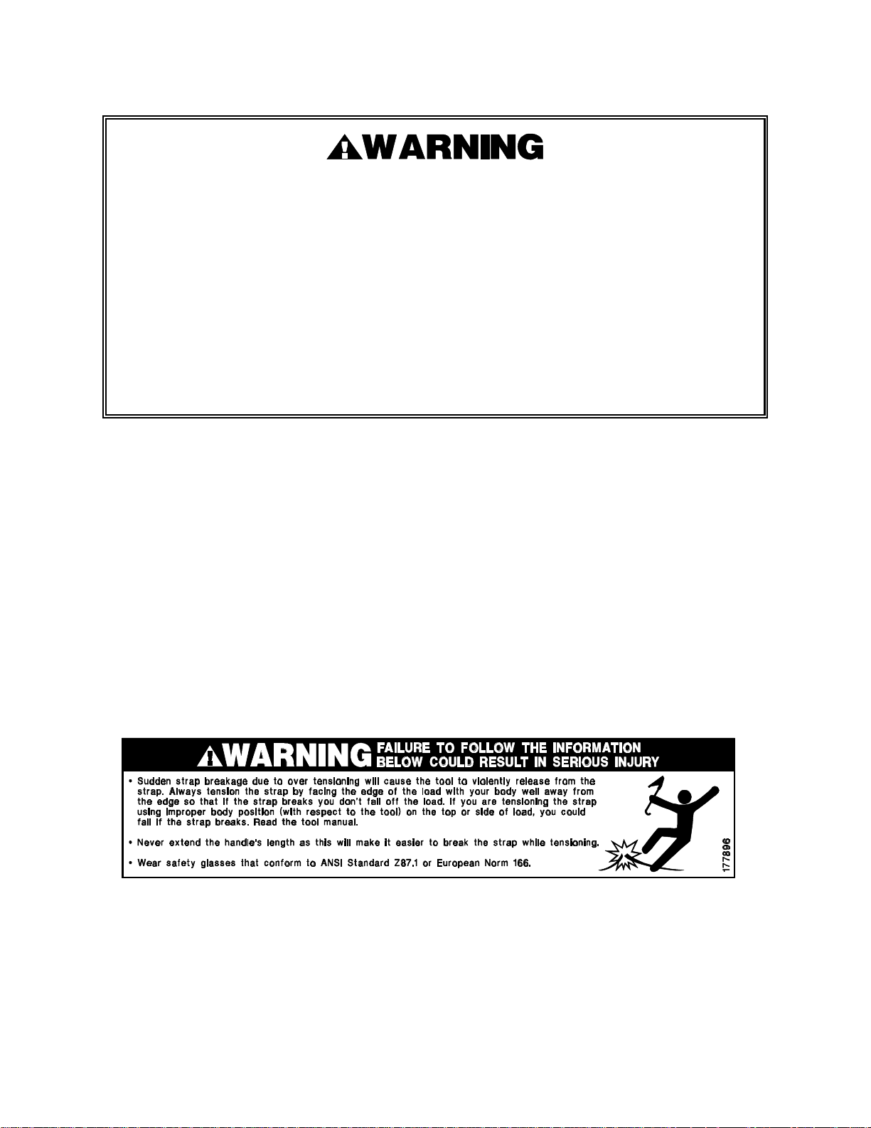
The warning label shown below (177896) is installed on every tool handle. If this label becomes
damaged, replace it immediately. Ensure that a plastic shrink tube sleeve us applied over the
label. Contact your Signode Sales Representative if you have any questions.
5
Page 6

STRAP PLACEMENT AROUND LOAD
1. Place strap around load as shown in the illustrations.
HORIZONTAL STRAP SIDE LOAD
VERTICAL STRAP SIDE LOAD
TOP STRAP LOAD
Failure to place the strap properly around the load or an unstable or shifted load could
result in a sudden loss of strap tension during tensioning. This could result in a sudden
loss of balance casing you to fall.
If the load corners are sharp use edge protectors.
Failure to follow the above could result in serious injury or death.
2. Thread the proper number of heavy duty seals on both straps, Contact your Signode Sales
Representative for recommendations. Bend the lower/inner strap backwards to hold seals in
place. Bend the upper/outer strap away from the load to permit insertion into the windlass of
tensioner.
6
Page 7
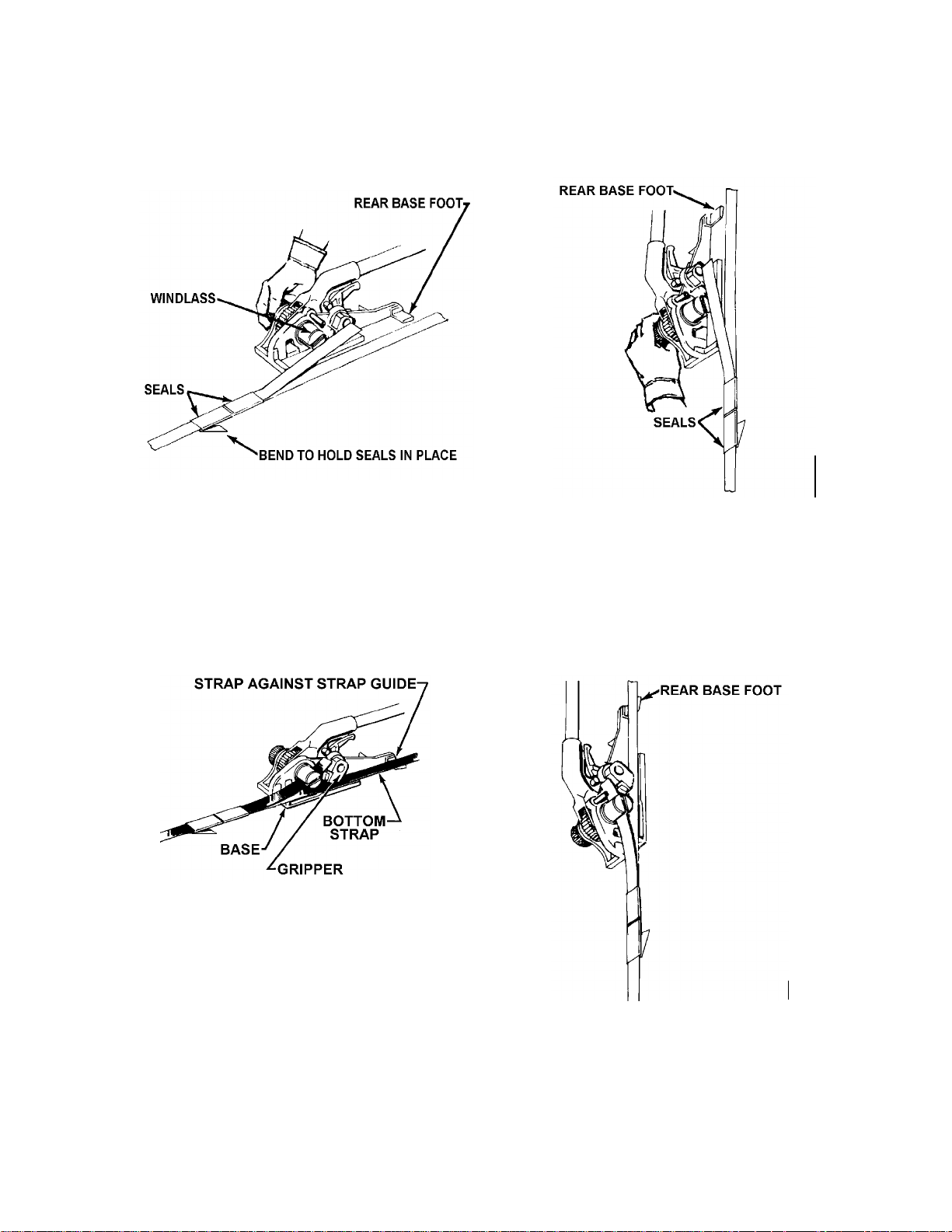
INSERTING STRAP INTO THE TOOL
1. Rotate the tensioning handle all the way down to lock the gripper in the open position.
Adjust the windlass so that the slot is in line with angle of strap.
TYPICAL ORIENTATION FOR TOP LOADS
TYPICAL ORIENTATION FOR SIDE LOADS
2. Insert lower/inner strap in opening between gripper and base of tensioner until the strap is
fully in contact with the inner wall of the base (strap guide). Make sure that the lower/inner
strap is inserted over the base foot. Insert top/outer strap fully into windlass slot.
Approximately 2 to 4 inches should extend beyond windlass; cut off any excessive length
before tensioning.
TYPICAL ORIENTATION FOR TOP LOADS
TYPICAL ORIENTATION
FOR SIDE LOADS
7
Page 8
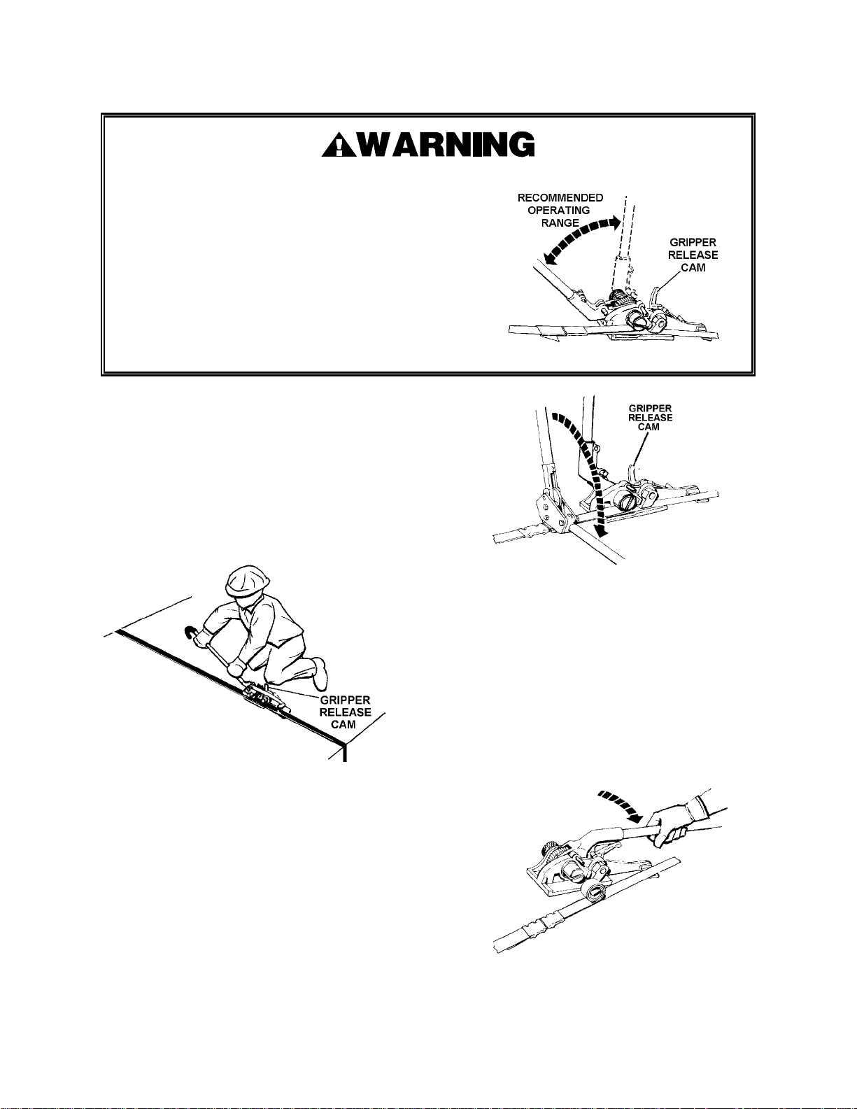
OPERATING INSTRUCTIONS FOR ON TOP OF LOAD
While tensioning strap, do not rotate the tensioning
handle to the point where it will contact the gripper
release cam. This will result in a sudden loss of strap
tension. Be careful when applying final tension, as
excessive tension could cause strap breakage.
Position yourself in such a manner that strap
breakage or hands slipping off the handle will not
cause a loss of balance. Never increase the length of
the tensioning handle by any means, such as, slipping
a pipe over the handle to extend its length. If you have
any questions contact your Signode Sales
Representative.
1. Bring tensioning handle upward,
allowing the gripper to contact the lower
strap. Rotate tensioning handle back
and forth to take up slack in strap. When
strap is snug, the operator should kneel
perpendicular to the strap and apply the
final tension using short tensioning
strokes.
2. Open sealer fully and center sealer jaws
of sealer over each seal. Crimp or notch
each seal the proper number of times by
bringing the top handle downward as far
as it will go.
Consult your sealer manual for the
proper number of crimps or notches
needed for your application.
3. Release tensioner from strap by bringing
handle down until gripper release cam
locks in tensioning handle pin. Remove
tensioner by twisting windlass slot out
of strap curl and sliding tool away from
strap.
8
Page 9
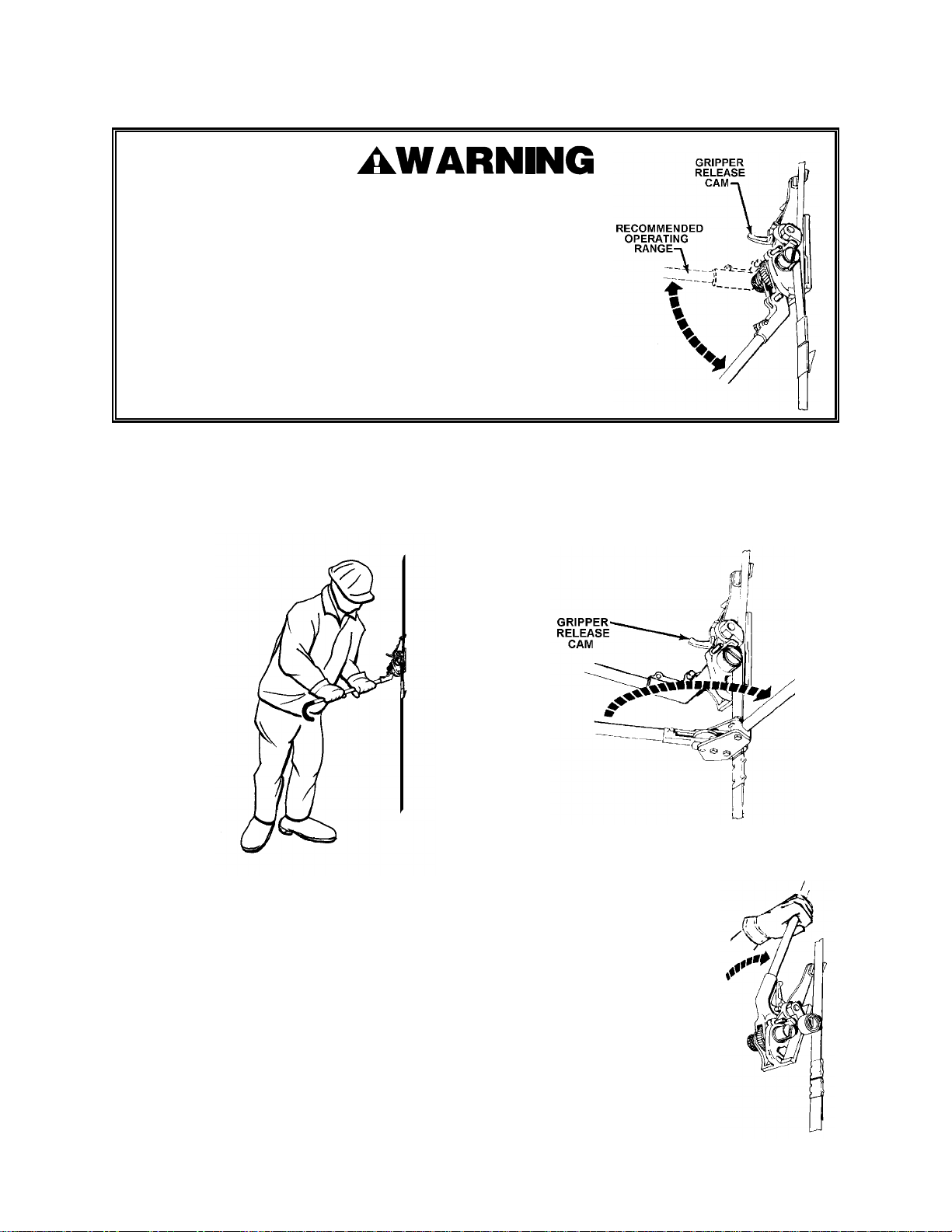
OPERATING INSTRUCTIONS FOR SIDE OF LOAD (VERTICAL)
While tensioning strap, do not rotate the tensioning handle
to
the point where it will contact the gripper release cam. This
will result in a sudden loss of strap tension. Be careful when
applying final tension, as excessive tension could cause
strap breakage. Position yourself in such a manner that strap
breakage or hands slipping off the handle will not cause a
loss of balance. Never increase the length of the tensioning
handle by any means, such as, slipping a pipe over the
handle to extend its length. If you have any questions
contact
your Signode Sales Representative.
1. Bring tensioning handle downward,
allowing the gripper to contact the lower
strap. Rotate tensioning handle back
and forth to take up
slack in strap. When
strap is snug, the
operator should
stand to the
side of the tool
and apply the
final tension
using short
tensioning
strokes.
2. Open sealer fully and center sealer jaws
of sealer over each seal. Crimp or notch
each seal the proper number of times by
bringing the top handle downward as far
as it will go.
Consult your sealer manual for the
proper number of crimps or notches
needed for your application.
3. Release tensioner from
strap by rotating
handle until it contacts
and locks into the
gripper release cam.
Remove tensioner by
twisting windlass slot
out of strap curl and
sliding tool away from
strap.
9
Page 10
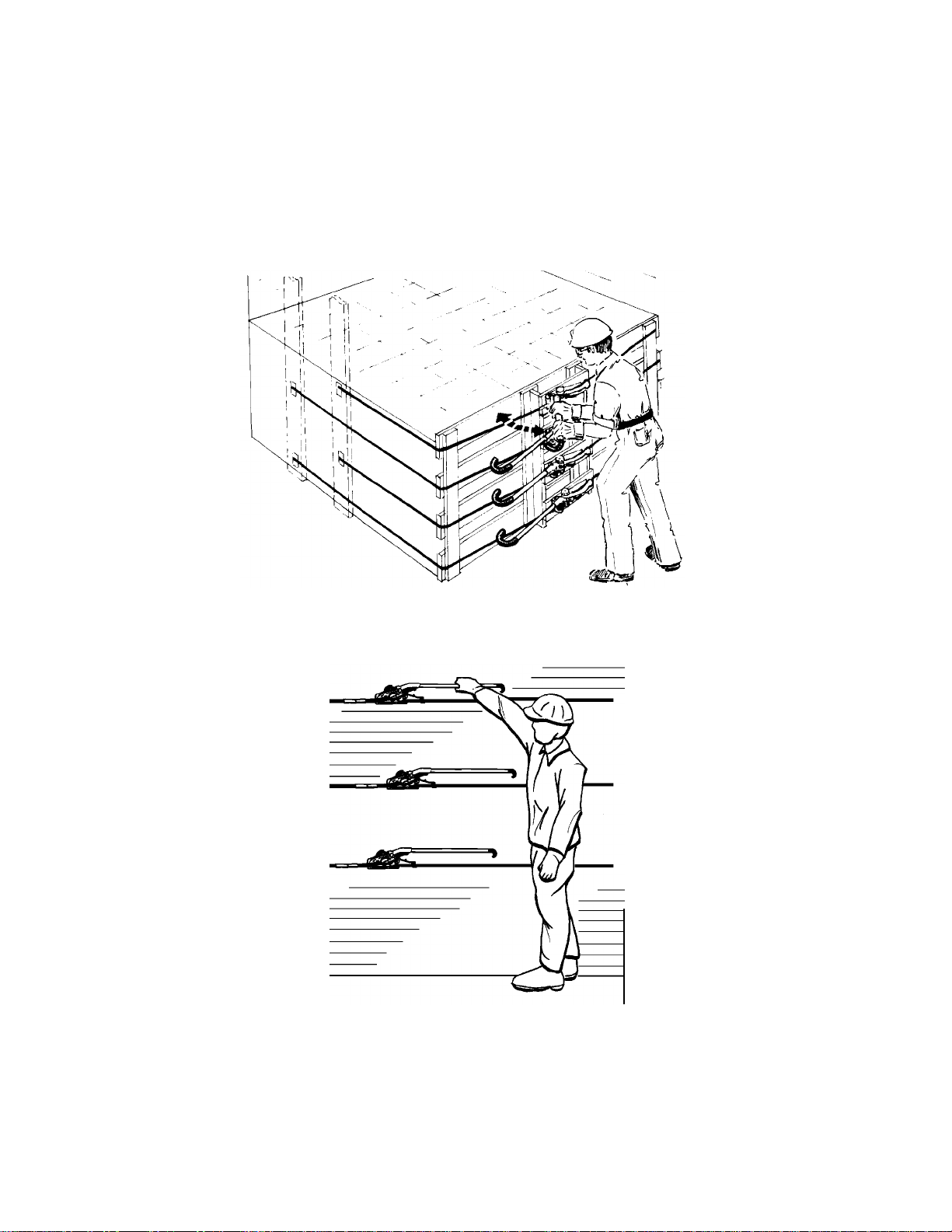
OPERATING INSTRUCTIONS FOR WALL ANCHORED
OR SIDE (HORIZONTAL) LOADS
The positioning of the tensioner on the strap for horizontal use is the same as on the top of load
operation. After the slack strap is taken up, final tension is applied by short push type strokes,
as illustrated below. Note that a tensioner is used on each strap to ensure equal tension. The
sealing operation is also the same as for top of load use (Refer to top of load instructions).
10
Page 11

BLANK
11
Page 12
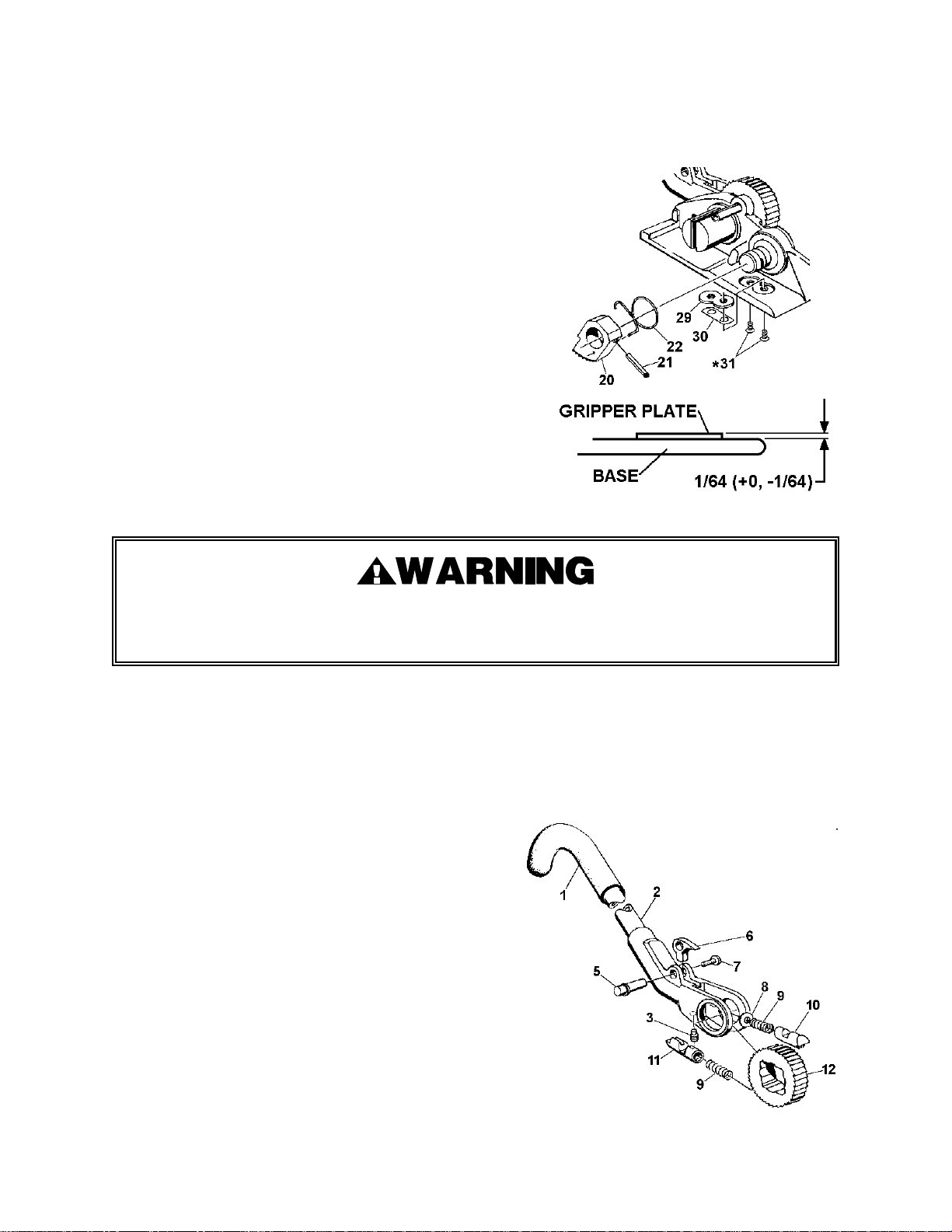
PART REMOVAL AND REPLACEMENT
GRIPPER, GRIPPER SPRING, GRIPPER PLATE
1. To remove the gripper and the gripper spring (20 and
22), drive the roll pin (21) out of the gripper using a
3/16" pin punch. Pull the gripper and gripper spring
off the gripper shaft. Inspect and replace as required.
Before reassembling, clean the exposed end of the
gripper shaft and lubricate using light machine oil. Do
not use grease. Reassemble in reverse order.
2. To replace the gripper plate (29) remove the two
gripper plate screws (31) and lift the gripper plate out
of the base. Be careful not to lose the shims (30)
beneath the gripper plate. Before installing a new
gripper plate, blow any dirt out of the hole in the base.
The gripper plate must be installed flush to 1/64"
above the base surface as shown in Figure 1. Apply
one drop of Loctite sealant #242 to each screw.
Reassemble in reverse order. After reassembling the
tool, do not use for 12 hours to permit Loctite sealant
to harden.
The top of the gripper plate must be only slightly above the top of the base. Failure to
install the gripper plate properly can cause a loss of strap tension.
TENSION HANDLE ASSEMBLY, WINDLASS SHAFT, AND RATCHET WHEEL.
1. Remove the retaining wire (19) from the windlass knob (17). Remove the cap screw (18) from
the windlass shaft (14). Pull the windlass knob off the end of the windlass shaft.
2. Slide the windlass shaft out of the base (32) and lift out the tension handle assembly. The
ratchet wheel can then be removed and inspected.
3. To remove the handle pawl (10) from the yoke
handle weldment (2), first remove the Klipring
Truarc (7) from the slot on the pawl pin (5). Press
the pawl pin out of the handle yoke by pushing on
the pin from the Truarc side of the pin. Once the
pawl pin is removed, remove the handle pawl
aligning set screw (3). The pawl cam, handle pawl,
pawl spring and spring washer (6, 10, 9 and 8) can
now be removed and inspected. Before
reassembling, clean all parts thoroughly in
solvent, particularly the hole in the handle yoke for
the handle pawl. Lubricate all moving parts with
light machine oil and reassemble in reverse order.
12
Page 13
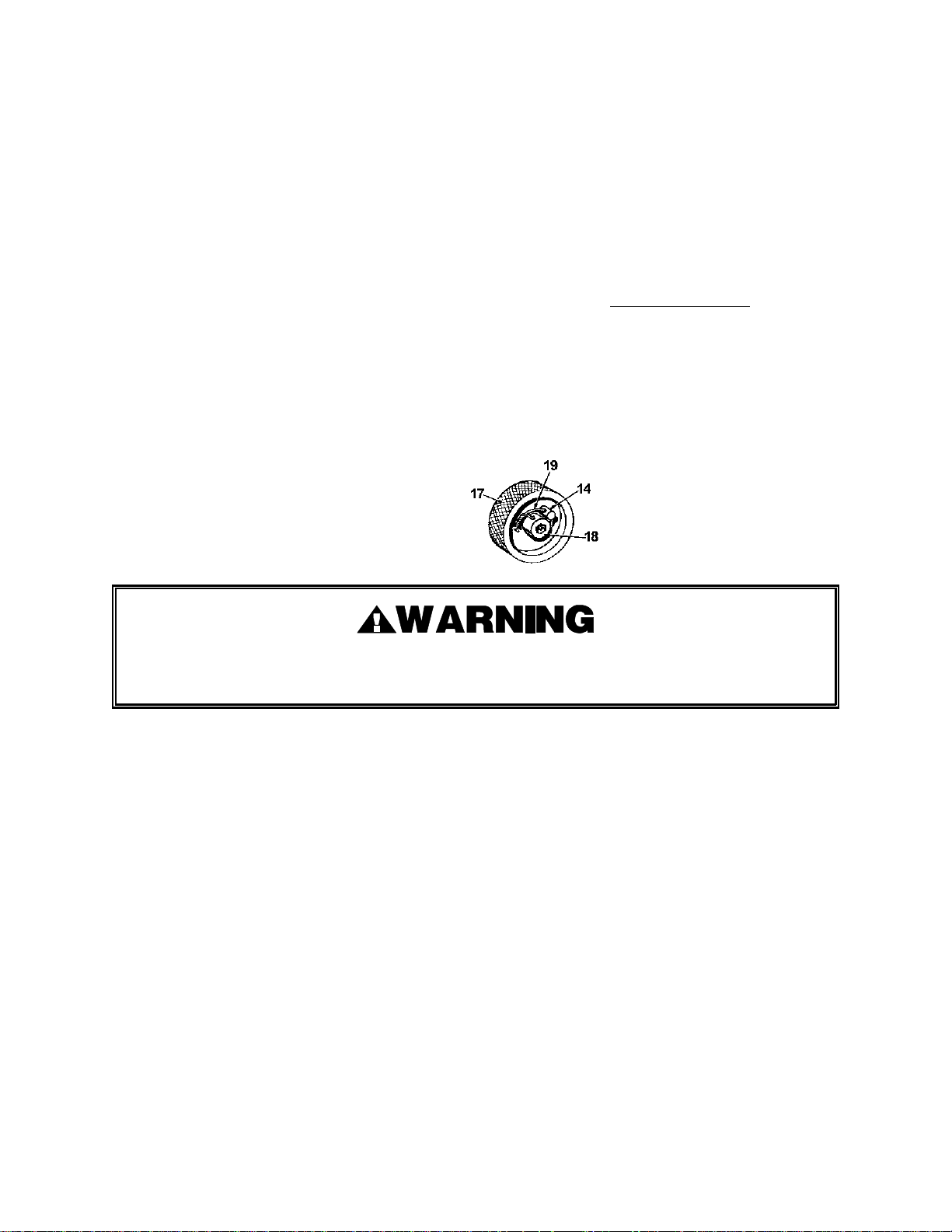
4. Should it be necessary to replace the windlass shaft bushings (15 and 16), it is recommended
that each bushing be driven out of the base by using pieces of rod or pipe with smaller
diameters than the holes in the base. If pipe of the correct size cannot be obtained, the
bushings can be driven out with a pin punch. Before installing new bushings, apply one
drop of Loctite sealant #242 to each outer bushing surface. It is recommended that the
bushings be pressed into the base. Be careful not to damage the edges of the bushings
during installation.
5. Before reassembling the tool, clean ratchet wheel, windlass shaft, and yoke handle assembly
thoroughly. Lubricate all moving parts with light machine oil. Do not use grease.
Reassemble in reverse order.
NOTE: To tighten cap screw on windlass knob, first rotate slot in the windlass shaft to
vertical position. Cut two (2) pieces of strap about 6" long and insert in windlass slot. Place
one drop of Loctite sealant #242 on cap screw threads. Use strap to prevent windlass from
turning as cap screw is tightened. DO NOT USE a screwdriver to prevent windlass from
turning as windlass slot can be damaged. After cap screw is tightened, install a new
retaining wire as shown.
THREAD WIRE (19) THROUGH HOLD IN
SCREW (18) AND THROUGH HOLE IN PIN
(14), TWIST WIRE ENDS UNTIL SNUG.
Never use Loctite or any similar adhesive on handle pawl aligning set screw (3) as this could
cause the handle pawl to stick and not engage the ratchet gear properly.
GRIPPER SHAFT, CAM PUSH ROD, AND BASE PAWL
1. Remove the gripper and the gripper spring in accordance with the instructions on the
previous pages.
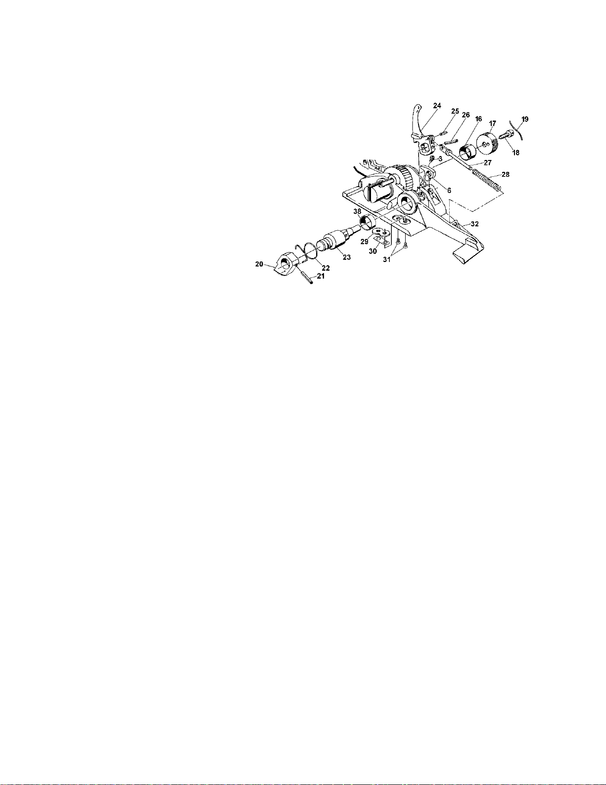
2. To remove the gripper shaft and the cam push rod, place the tension handle assembly in the
forward position and manually return the gripper release cam (24) to the full rear position.
Working from the top of the tool with a pin punch, drive the roll pin (26) out of the gripper
release cam. It will be necessary to rotate the gripper release cam forward after the roll pin is
part way through the gripper release cam to obtain clearance to drive the roll pin all the way
out. After the roll pin is removed, rotate the gripper release cam to the full forward position.
Tap the gripper shaft (23) out of the base. Once the gripper shaft is removed, the gripper
release cam, cam push rod, spring, and pawl cam (24, 27, 28 and 6) can be removed and
inspected.
13
Page 14
PART REMOVAL AND REPLACEMENT, Continued
3. Should it be necessary to
replace or service the base pawl
(11), the tension handle
assembly, windlass shaft, and
the ratchet wheel must be
removed first. See instructions
on previous pages. Once the
ratchet wheel is removed,
remove the base pawl aligning
set screw (3). The base pawl
and spring can now be removed
and inspected.
4. Before reassembling the tool,
clean all parts thoroughly in
solvent and allow to dry
completely. All moving parts
should be lubricated with light
machine oil.
5. To reassemble the tool, install the pawl spring, set screw, and base pawl into the base. Next,
assemble the ratchet wheel, tension handle assembly, and windlass shaft. See instructions
on previous pages. To install the gripper shaft, use the following procedure:
a. Ensure that the gripper release cam (24) is pinned to the cam push rod (27) with the roll
pin (25).
b. Slide cam push rod spring (28) onto the cam push rod.
c. Set gripper release cam assembly into the appropriate position in the base with end of
the cam push rod extending through the hole in the base.
d. Set pawl cam (6) in position in the base.
e. Insert the gripper shaft into the base and through the gripper release cam. The gripper
shaft will only go part way through the gripper release cam.
f. Pull the gripper release cam to the full rear position, see Figure 4.
g. Insert a screwdriver between the gripper release cam and the base. Use the screwdriver
to pry the gripper release cam towards the rear of the tool. At the same time, rotate the
gripper shaft until the square part of the gripper shaft slides into the square hole in the
gripper release cam.
NOTE: When sliding the gripper shaft into the gripper release cam, ensure that the wide
radius on the gripper shaft is facing down.
14
Page 15

h. Push the gripper shaft fully into the base.
i. Remove the screwdriver and install the roll pin (26) into the hole in the gripper release
cam.
j. Install the gripper (20) and gripper spring (22).
NOTE: After the tool is reassembled, crank the tension handle several times to be sure that
set screws (3) are not binding the handle pawl or base pawl. If either pawl is binding, turn the
appropriate set screw counterclockwise 1/2 turn at a time and recheck each time by cranking
the handle.
15
Page 16
TROUBLESHOOTING
The following items are the most common tool symptoms if problems occur. For symptoms or
remedies not shown, contact your Signode service representative for additional information and
details. The following tool symptoms are shown in this manual:
#1 - Gripper will not hold lower strap.
#2 - Strap slides off windlass shaft during tensioning.
#3 - Tensioning handle slips during tension stroke.
#4 - Tool will not hold tension.
#1 SYMPTOM: Gripper will not hold lower strap.
CAUSE REMEDY
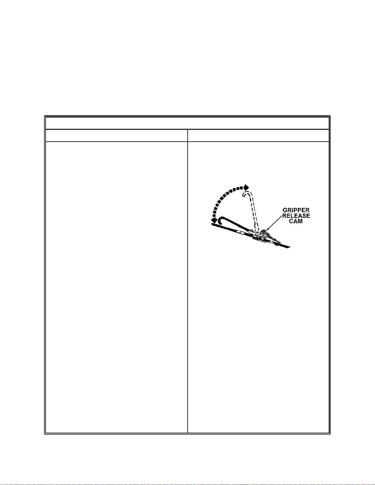
1. Operator is bringing tension handle too
far back allowing tension handle to hit
gripper release cam.
2. Gripper spring (22) is weak or broken.
3. Dirt in gripper teeth.
4. Gripper teeth worn.
1. While tensioning strap, do not rotate
the tensioning handle to the point
where it will contact the gripper release
cam. This will result in a loss of strap
tension.
2. Replace gripper spring. See Parts
Removal and Replacement
Instructions.
3. Clean gripper teeth and apply light
machine oil to end of gripper shaft. Do
not use grease.
4. Replace gripper and apply light
machine oil to end of gripper shaft. Do
not use grease.
5. Gripper plate (29) is worn. Top of plate
must be above base.
6. Dirt or rust has accumulated between
gripper and gripper shaft preventing
gripper from rotating.
7. A bent or dirty cam push rod (27) or
weak spring (25) prevents gripper shaft
from rotating.
5. Replace gripper plate. See Parts
Removal and Removal Instructions.
6. Remove gripper (see Parts Removal
and Removal Instructions). Clean hole
in gripper and exposed end of gripper
shaft, then lubricate using light
machine oil. Do not use grease.
7. Replace cam push rod and spring.
Clean and apply light machine oil to all
moving parts.
16
Page 17
#2 SYMPTOM: Strap slides off windlass shaft during tensioning.
CAUSE REMEDY
1. Strap not inserted fully inserted into
windlass shaft slot during strap
loading.
2. Tool is not kept in line with strap
during tensioning.
3. Excessive amount of strap being
wound onto windlass shaft.
#3 SYMPTOM: Tensioning handle slips during tension stroke.
CAUSE REMEDY
1. Handle pawl is clogged by dirt or rust
preventing free movement of handle
pawl.
2. Tip of handle pawl is heavily worn or
chipped.
3. Teeth on ratchet wheel are heavily worn
or chipped.
1. Push strap fully into slot during initial
tensioning strokes. See Operating
Instructions for details.
2. Keep tensioning handle in line with
strap during tensioning.
3. Cut off strap 2 to 4" beyond windlass.
See Operating Instructions for details.
1. Remove tension handle, handle pawl,
spring and ratchet wheel. Clean parts
and hole in handle yoke and apply
light machine oil to moving parts. See
Parts Removal and Replacement.
2. Replace handle pawl and lubricate with
light machine oil. See Parts Removal
and Replacement.
3. Replace ratchet wheel and lubricate
with light machine oil. See Parts
Removal and Replacement.
4. Windlass shaft bushings (15 and 16)
are heavily worn allowing windlass
shaft to wobble. This may cause
improper ratchet wheel/handle pawl
alignment.
4. Replace bushings and lubricate with
light machine oil. See Parts Removal
and Replacement.
17
Page 18
TROUBLESHOOTING, Continued
#4 SYMPTOM: Tool will not hold tension.
CAUSE REMEDY
1. Base pawl is clogged by dirt preventing
free movement of base pawl.
2. Tip of base pawl is heavily worn or
chipped.
3. Teeth on ratchet wheel are heavily worn
or chipped.
4. Windlass shaft bushings (15 and 16)
are heavily worn allowing windlass
shaft to wobble. This may cause
improper ratchet wheel/handle pawl
alignment.
1. Remove base pawl,spring and ratchet
wheel. Clean parts and hole in handle
yoke and apply light machine oil to
moving parts. See Parts Removal and
Replacement.
2. Replace base pawl and lubricate with
light machine oil. See Parts Removal
and Replacement.
3. Replace ratchet wheel and lubricate
with light machine oil. See Parts
Removal and Replacement.
4. Replace bushings and lubricate with
light machine oil. See Parts Removal
and Replacement.
18
Page 19

BLANK
19
Page 20

PARTS LIST
4A1-114 4A1-114KR 4A1-2
KEY QTY. PART NO. PART NO. PART NO. DESCRIPTION
1 1 171652 171652 171652 Handle grip
2 1 171955 171955 179023 Yoke handle assembly
3 2 173956 173956 173956 Set screw, Nylock
5 1 006768 -- 006768 Pawl pin
5A 1 -- 005568 -- Pawl pin
6 2 006767 006767 006767 Pawl cam
7 1 086190 086190 086190 Klipring, Truarc #5304-77
8 1 006746 006746 006746 Pawl spring washer, 1/4 SAE Std.
9 2 006769 006769 006769 Pawl spring
10 1 006711 006711 006711 Handle pawl
11 1 006712 006712 006712 Base pawl
12 1 006762 006762 006762 Ratchet wheel
13 1 006920 006920 -- Roll pin, 3/8 x 1 5/8
13A 1 -- -- 071804 Roll pin, 3/8 x 2 1/4
14 1 005908 005908 005909 Windlass shaft assembly
15 1 008675 008675 008675 Bushing
16 1 008682 008682 008682 Bushing
17 1 006705 006705 006705 Windlass knob
18 1 006748 006748 006748 Cap screw, 5/16-18 x 3/4
19 1 007184 007184 007184 Retaining wire
20 1 006758 006758 006758 Gripper
21 1 006787 006787 006787 Roll pin, 3/16 x 1
22 1 006788 006788 006788 Gripper spring
23 1 005907 005907 005912 Gripper shaft
24 1 006765 -- 006765 Gripper release cam
24A 1 -- 005565 -- Gripper release cam
25 1 006738 006738 006738 Roll pin, 5/32 x 3/8
26 1 006737 006737 006737 Cam retaining pin (roll pin), 5/32 x 1
27 1 006739 006739 006739 Cam push rod
28 1 006741 006741 006741 Cam push rod spring
29 1 006742 006742 006742 Gripper plate
30 A/R 005913 005913 005913 Shim
31 2 004860 004860 006789 Gripper plate screw
32 1 163321 -- -- Base
32A 1 -- -- 163333 Base
32B 1 -- 163327 -- Base, not shown
33 1 -- -- 006740 Push rod swivel
34 1 -- -- 006698 Gripper stop pin
35 1 177896 177896 177896 Warning sign
36 1 002481 002481 002481 Nameplate
37 2 002163 002163 004939 Drive screw
38 1 424193 424193 424193 DU Bearing (14DU12)
!! When ordering parts, please show tool model, part number and name.
!! All recommended spare parts are underlined and should be stocked.
!! Standard hardware parts may be obtained from local hardware suppliers.
20
Page 21
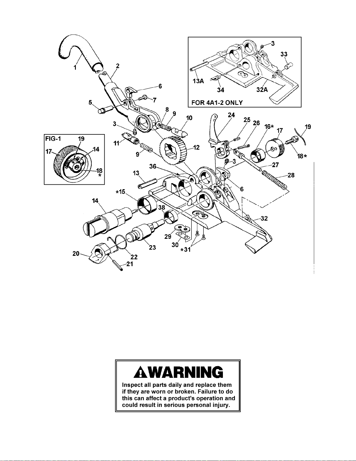
* Use Loctite #242.
NOTES:
1. Thread wire (19) through hole in screw (18) and through hole in pin (14). Twist wire ends until
snug (See Figure 1 above).
2. Assemble Key Nos. 13, 15 and 16 with slot facing up.
3. Do not apply sealant to small screws or to moving parts as liquid spreads easily.
4. Clean tool at least once a week and apply light machine oil to all moving parts daily.
21
Page 22

BLANK
22
Page 23

BLANK
23
Page 24
SIGNODE
NEW TOOL WARRANTY
Signode Engineered Products Warrants that a new Signode strapping tool will operate per functional
specifications for a period of sixty (60) days after the date of shipment to the owner's place of business.
Normal wearing parts, as outlined in the Operation, Parts & Safety manual, are covered by a thirty (30)
day warranty unless, in Signode's judgement, these parts have been subjected to abnormal or extreme
usage. Signode's sole liability hereunder will be to repair or replace, without charge, F.O.B. Signode's
Glenview, Illinois plant, any tool which proves to not operate per functional specifications within the
stated period. Signode reserves the right to replace any tool which proves not to operate per functional
specifications with a new or like-new tool of the same model if in Signode's judgement such replacement
is appropriate. Any new replacement tool provided to an owner will carry a full sixty (60) day warranty.
Any warranty repaired tool or like-new replacement tool will carry a warranty for the balance of the time
remaining on the initial sixty (60) day warranty. This warranty will be extended to compensate for the
time the tool is in Signode's possession for warranty repairs.
This warranty is void as to any tool which has been: (I) subjected to mis-use, misapplication, accident,
damage, or repaired with other than genuine Signode replacement parts, (II) improperly maintained, or
adjusted, or damaged in transit or handling; (III) used with improperly filtered, unlubricated air or
improper strapping material, (IV) in Signode's opinion, altered or repaired in a way that affects or
detracts from the performance of the tool.
SIGNODE MAKES NO WARRANTY, EXPRESSED OR IMPLIED, RELATING TO MERCHANTABILITY,
FITNESS OR OTHERWISE EXCEPT AS STATED ABOVE AND SIGNODE'S LIABILITY AS ASSUMED ABOVE
IS IN LIEU OF ALL OTHERS ARISING OUT OF OR IN CONNECTION WITH THE USE AND PERFORMANCE
OF THE TOOL. IT IS EXPRESSLY UNDERSTOOD THAT SIGNODE SHALL IN NO EVENT BE LIABLE FOR
ANY INDIRECT OR CONSEQUENTIAL DAMAGES INCLUDING, BUT NOT LIMITED TO, DAMAGES WHICH
MAY ARISE FROM LOSS OF ANTICIPATED PROFITS OR PRODUCTION, SPOILAGE OF MATERIALS,
INCREASED COSTS OF OPERATION OR OTHERWISE.
Considerable effort has be made to ensure that this product conforms to our high quality standards.
However, should you experience any difficulties, please contact your Sales Representative providing
samples and the manufacturing code specified on the tool.
Thank you for your help.
SIGNODE ENGINEERED PRODUCTS
Hand Tool Division
3620 W. Lake Avenue, Glenview, Illinois 60025
© Copyright 2002, Signode 186021 Rev. 12/2002
 Loading...