

Page 1

ST TYPE STRAP TENSIONER
Part No. 003480
TOOL SPECIFICATIONS
STRAP TYPE WIDTH THICKNESS
Apex, Magnus 3/8"(9.5mm) to 3/4"(19.0mm) .015"(0.38mm) to .025"(0.63mm)
Refer to Signode Operation, Parts & Safety Manual part number 186006
for additional part removal & replacement details and information.
IMPORTANT - DO NOT DESTROY THIS MANUAL. It is the customer's responsibility to have all operators
and service personnel read and understand this manual. Contact your local Signode representative for
additional copies of this manual.
© Copyright 2003, Signode 286164 Rev. 5/2003
PLEASE NOTE:
Page 2
GENERAL SAFETY INSTRUCTIONS - READ THESE INSTRUCTIONS CAREFULLY.
FAILURE TO FOLLOW THESE INSTRUCTIONS CAN RESULT IN SEVERE PERSONAL INJURY.
GENERAL CONSIDERATIONS
1. EYE INJURY HAZARD.
Failure to wear safety glasses with side
shields can result in severe eye injury or
blindness. Always wear safety glasses
with side shields which conform to ANSI
Standard Z87.1 or EN 166.
2. STRAP BREAKAGE HAZARD.
Improper operation of the tool or sharp
corners on the load can result in strap
breakage during tensioning, which could
result in the following:
! A sudden loss of balance causing you to fall.
! Both tool and strap flying violently towards
your face.
Failure to place the strap properly around the load or on
an unstable or shifted load could result in a sudden loss
of strap tension during tensioning. This could result in a
sudden loss of balance causing you to fall.
Read the tools operating instructions. If the load corners
are sharp use edge protectors. Place the strap correctly
around a properly positioned load.
! Positioning yourself in-line with the strap, during
tensioning and sealing, can result in severe personal
injury from flying strap or tool. When tensioning or
sealing, position yourself to one side of the strap and
keep all bystanders away.
7. WORK AREA
Keep work areas uncluttered and well lit.
8. CUTTING TENSIONED STRAP
Using claw hammers, crowbars, chisels, axes or similar
tools will cause tensioned strap to fly apart with
hazardous force. Use only cutters designed for cutting
strap. Read the instructions in the cutters manual for
proper procedure in cutting strap. Before using any
Signode product read its operation and safety manual.
Several combinations of strap, seals and tools can be used
with this tensioner. Use the correct Signode products for your
application. If you need help contact your Signode
Representative.
SAFETY PROCEDURES FOR TOOL OPERATION
1. Before using this tensioner, read all the instructions in
this Operation, Parts and Safety Manual.
2. NEVER HANDLE OR SHIP ANY LOAD WITH IMPROPERLY
FORMED SEALS. Misformed seals may not secure the
load and could cause serious injury. Inspect the tool for
worn and/or damaged parts. Replace tool parts as
needed.
If seals are not being properly formed:
A. Ensure that the tool's operating instructions are
being followed before applying another strap.
B. Cut the strap off and apply another.
! Using strap not recommended for this tensioner can
result in strap breakage during tensioning. Use the
correct Signode products for your application.
3. FALL HAZARD.
Maintaining improper footing and/or balance when
operating the tool can cause you to fall. Do not use the
tool when you are in an awkward position.
4. CUT HAZARD
Always wear protective gloves when
handling strap or sharp parts.
5. TRAINING.
This tool must not be used by persons not
properly trained in its use. Be certain that you receive
proper training from your employer. If you have any
questions contact your Signode Representative.
6. TOOL CARE.
Take good care of the tool. Inspect and clean it daily,
lubricate it weekly. Replace any worn or broken parts.
3. Tuck strap end back into the dispenser when not in use.
MAINTENANCE/CLEANING
Debris accumulated in the teeth of either the feedwheel or the
clutch plug must be removed with a small wire brush. A need
to clean the teeth will become apparent when either the
feedwheel skids on the strap or the lower strap slips on the
clutch plug during tensioning.
2
Page 3
OPERATING INSTRUCTIONS
Wear safety glasses which conform to ANSI Standard
Z87.1 or EN 166.
Always position yourself to one side of the strap
while tensioning and sealing. Make sure all
bystanders are clear before proceeding. Maintain
proper footing and balance.
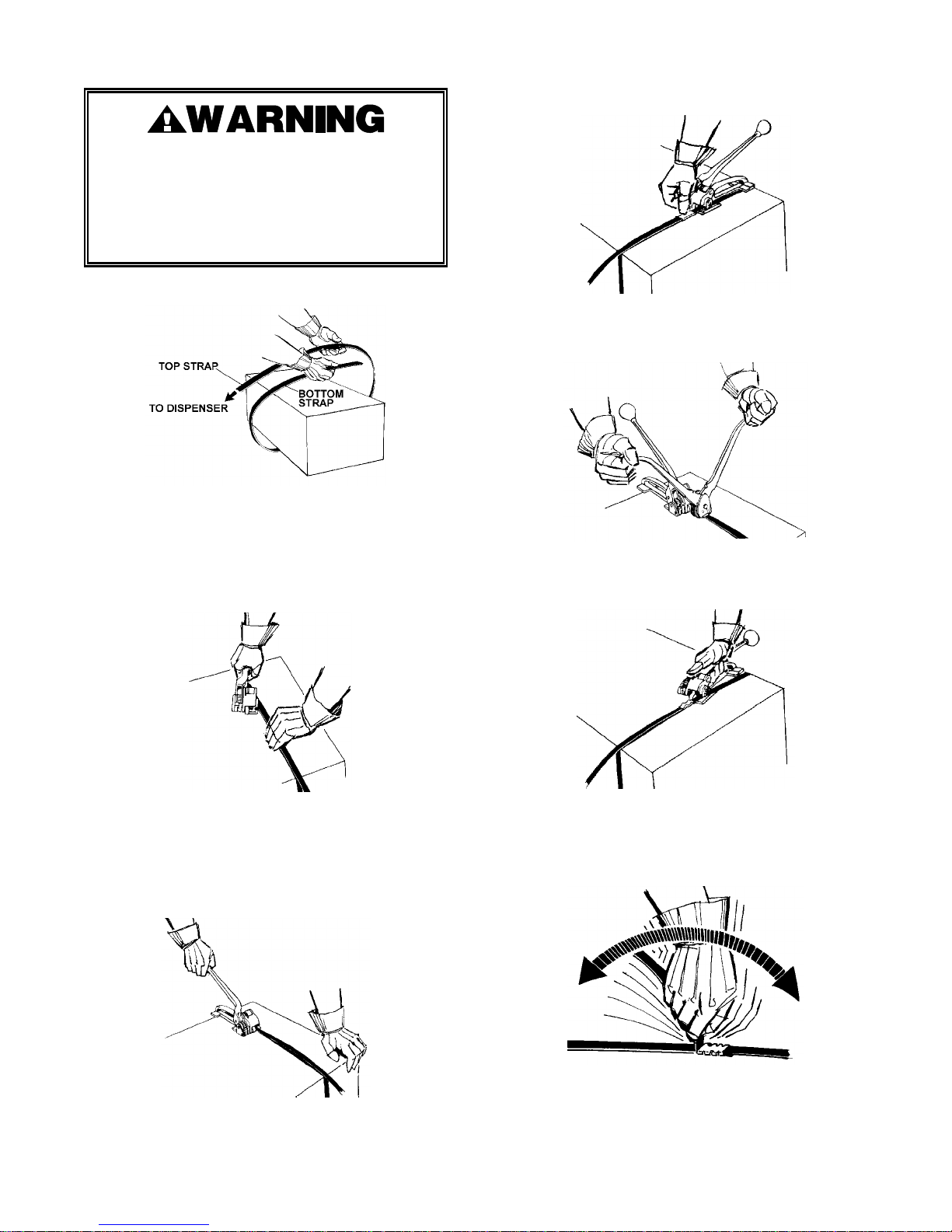
1. Encircle the package with strap as illustrated. Take up the
slack, keeping the strap squarely in line.
2. Hold the hand-tensioned strap in position with the left
hand, grasp the tool in the right hand and squeeze the
handle to the base to lift the feedwheel. Position the rear
foot over the strap and slide the front foot under the
overlapping ends, approximately 1" (25mm) ahead of the
lower strap end. Make sure both straps have been fully
inserted into the tool. The inner edges of the strap must
butt up against the inner edge of the tool.
4. Snap a seal on the straps directly in front of the tool,
making sure that the seal covers both straps.
5. Hold the sealing tool at a right angle to the strap and rest
it squarely over the seal. Seal the tensioned strap by
bringing both sealer handles together as far as they will
go.
6. Return the handle to rest on the tool and press down on
the handle pawl with thumb. Squeeze the handle to the
base and remove the tool from the strap by swinging the
rear foot out as illustrated.
3. Release grip on tool to engage straps. Make sure the
strap is in alignment with the tool. While standing to one
side of the strap line, tension the strap through
continuous up and down motions with the tensioning
handle. NOTE: Do not allow the handle to press against
the base during the downward portion of the tensioning
cycle. This will raise the feedwheel and release the
tensioned strap.
7. Excess strap is bent sharply back on the seal with the
thumb or fingers. One and a half or two additional bends
will result in a clean strap break off. If the width and
gauge of the strap being used will not allow it to be bent,
cut the excess strap as close to the seal as possible
using an approved strap cutter.
3
Page 4
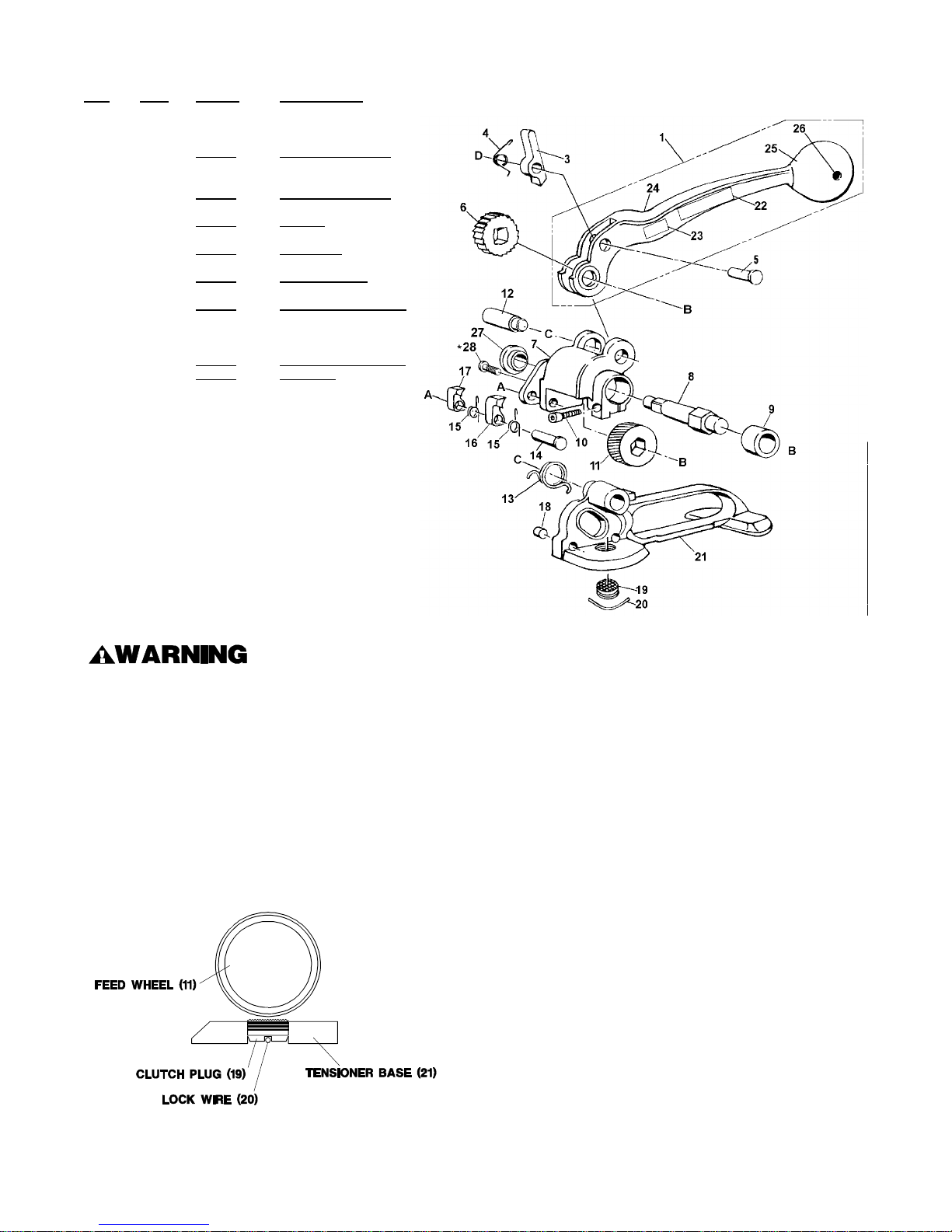
ST TENSIONER PARTS LIST
KEY QTY. PART # DESCRIPTION
1 1 273894 Handle assembly
3 1 003492 Handle pawl
4 1 003489 Handle pawl spring
5 1 003494 Handle pawl pin
6 1 003488 Ratchet gear
7 1 003490 Feedwheel support
8 1 003487 Feedwheel shaft
9 1 003478 Bearing
10 1 004502 SHCS, 10-32 x 5/8
11 1 003482 Feedwheel
12 1 003491 Support pin
13 1 003479 Support spring
14 1 003486 Retaining pawl pin
15 2 003483 Retaining pawl spring
16 1 003484 Long retaining pawl
17 1 003485 Short retaining pawl
18 2 001656 Strap guide pin
19 1 273748 Clutch plug assembly
20 1 001644 Lock wire
21 1 003497 Base
22 1 002471 Nameplate
23 1 003133 Caution plate
24 1 003493 Handle
25 1 306927 Knob
26 1 010057 Roll pin, ¼D x 1-¾LG
27 1 424250 Bushing
28 1 424251 BHCS, 1/4-28 x 1/4
When ordering parts, please show tool model, part
number, and description. All recommended spare parts
are underlined and should be stocked.
* Apply one drop of Loctite #271 (Red) or equivalent,
available as Signode Part No. 422796.
NOTE: Keys numbers 8, 27 and 28 can be ordered
together as Gear Housing Kit, Signode part No. 424436
All parts must be periodically inspected and replaced if worn or broken. Failure to do this can affect a
product's operation and can result in personal injury.
CLUTCH PLUG ADJUSTMENT
1. Remove the lock wire (Key 20) with needle nose pliers.
2. Using a flat head screwdriver, tighten the clutch plug (19)
so that it touches the feedwheel. Then back it off one
groove to align it with the lock wire holes in the tool base.
Be sure the clutch plug and the feedwheel do not touch.
3. Replace the lock wire over the grooves in the clutch plug
and hammer flat. To be sure the lock wire is secure, place a
screwdriver across the center of the lock wire and tap once
more.
4
 Loading...