

Signify North America Corporation Signify Canada Ltd.
200 Franklin Square Drive 281 Hillmount Road,
Somerset, NJ 08873 Markham, ON, Canada L6C 2S3
Telephone 855-486-2216 Telephone 800-668-9008
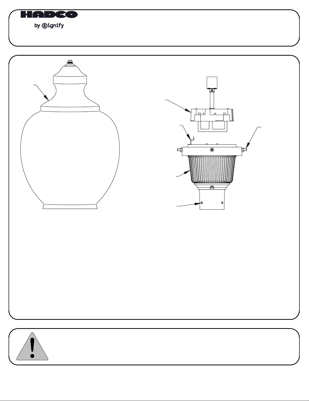
GLOBE
BALLAST
COVER
INSTALLATION INSTRUCTIONS:
FOR THE V72 FIXTURES
SPRING CLIP
SET SCREW
& LOCKNUT
FOR GLOBE
BALLAST
HOUSING
SET SCREW
FOR POST
(V72 SHOWN)
CAUTION
1. The electrical power must be disconnected from the fixture and pole before installing, servicing, or
relamping the fixture.
2. These directions must be read carefully and adhered to. Failure to do so may result in injury, damage to
the fixture, and voiding the warranty.
TOOLS REQUIRED
FOR INSTALLATION & RELAMPING
1. 5/32" Allen wrench
2. Wire connectors for appropriate wire
3. Phillips head screw driver
4. 1/2" Socket wrench
This fixture is intended for installation in accordance with the National Electrical Code and local code
specifications. Failure to adhere to these codes and instructions may result in serious injury and/or damage
to the ballast and void the warranty. These instructions do not purport to cover all details or variations in
equipment, nor to provide for every possible contingency related to installation, operation, maintenance,
or mounting situation. Should specific problems occur that are not addressed by these instructions, contact
your Sales Representative or distributor for assistance. Retain these instructions for future reference.
32000512, revision E
page 1 of 2
INSTALLATION
WARNING - The power MUST be turned off prior to proceeding. Read these instructions carefully.
If any problems are encountered that are not covered in these instructions, contact Hadco
for assistance.
STEP 1: REMOVE GLOBE
Loosen the (4) set screws and lock nuts that secure the globe
to the fixture. Lift the globe off of the fixture.
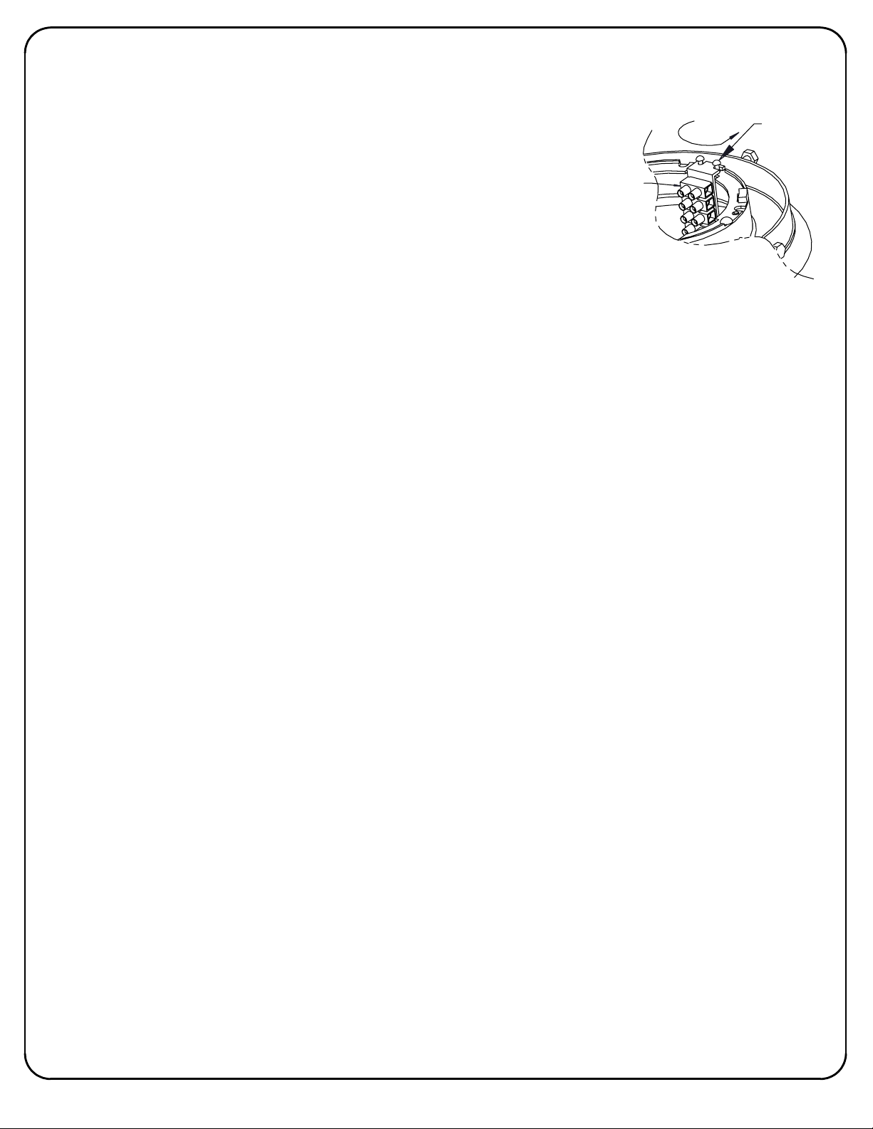
STEP 2: WIRING
TERMINAL
BLOCK
*Using wire nuts:
Wire bug the incoming power supply wires to the fixture's supply wires.
-OR *Using Internal Terminal Block
1. Push the spring clip away from the ballast cover with thumb and rotate the ballast
cover counter-clockwise until it stops.
2. Lift the ballast cover away from the fixture and disconnect the blue quick-connectors.
3. Loosen the (2) 8-32 screws and rotate the terminal block bracket to remove it from
the housing.
4. Remove the outwires, supplied by Hadco, from the terminal block.
5. Install the incoming power supply wires into the terminal block.
- First, verify that the voltage lead coming from the ballast is the same as the incoming
voltage.
- Then proceed to connect the common supply line with the fixture common, the ground
supply with the fixture ground, and the supply voltage with the fixture voltage.
6. Replace the terminal block bracket and tighten the two screws.
7. Replace the ballast cover by reversing steps 1 & 2. Verify that the spring clip snaps
back into place and secures the ballast cover to the fixture.
STEP 3: Mount the housing onto a 3" post shaft or tenon.
Use the post fitter's 5/16-18 set screws, supplied by Hadco, to secure the housing to the
post shaft or tenon.
STEP 4: Install the correct lamp as specified on the lamp label next to the socket.
STEP 5: Replace globe and tighten globe set screws and lock nuts.
STEP 6: Connect power and test the fixture for proper operation.
(2) 8-32
SCREWS
TO REPLACE LAMP
NOTE: It is a good idea to clean the fixture each time you relamp. Avoid using harsh solvents
or abrasives.
STEP 1: Remove the globe. See STEP 1 from INSTALLATION above.
STEP 2: Remove the old lamp and dispose of it in accordance with local codes and regulations.
STEP 3: Install a new lamp, referring to the lamp label next to the socket to ensure using the
correct type.
STEP 4: Replace the globe and tighten the globe set screws and lock nuts.
TO REPLACE BALLAST
STEP 1: Remove globe. See STEP1 from INSTALLATION above.
STEP 2: Remove ballast cover. See STEP 2, 1 & 2 from INSTALLATION above.
STEP 3: Make sure that the current lamp type and wattage correspond with the NEW ballast
type and wattage.
STEP 4: Check the NEW ballast module for correct voltage.
STEP 5: Install the new ballast cover (with new ballast). See STEP 2, 7 from INSTALLATION above.
STEP 6: Replace lamp and globe and tighten globe set screws.
DISCLAIMER
While we believe these instructions to be accurate at the time of publication, Hadco reserves the right to make
changes to this fixture and/or components. The contractor should follow local and National Electrical Codes
where required. For any further information please contact Hadco customer service.
32000512, revision E
page 2 of 2
 Loading...