

Page 1
Signify North America Corporation Signify Canada Ltd.
200 Franklin Square Drive 281 Hillmount Road,
Somerset, NJ 08873 Markham, ON, Canada L6C 2S3
Telephone 855-486-2216 Telephone 800-668-9008
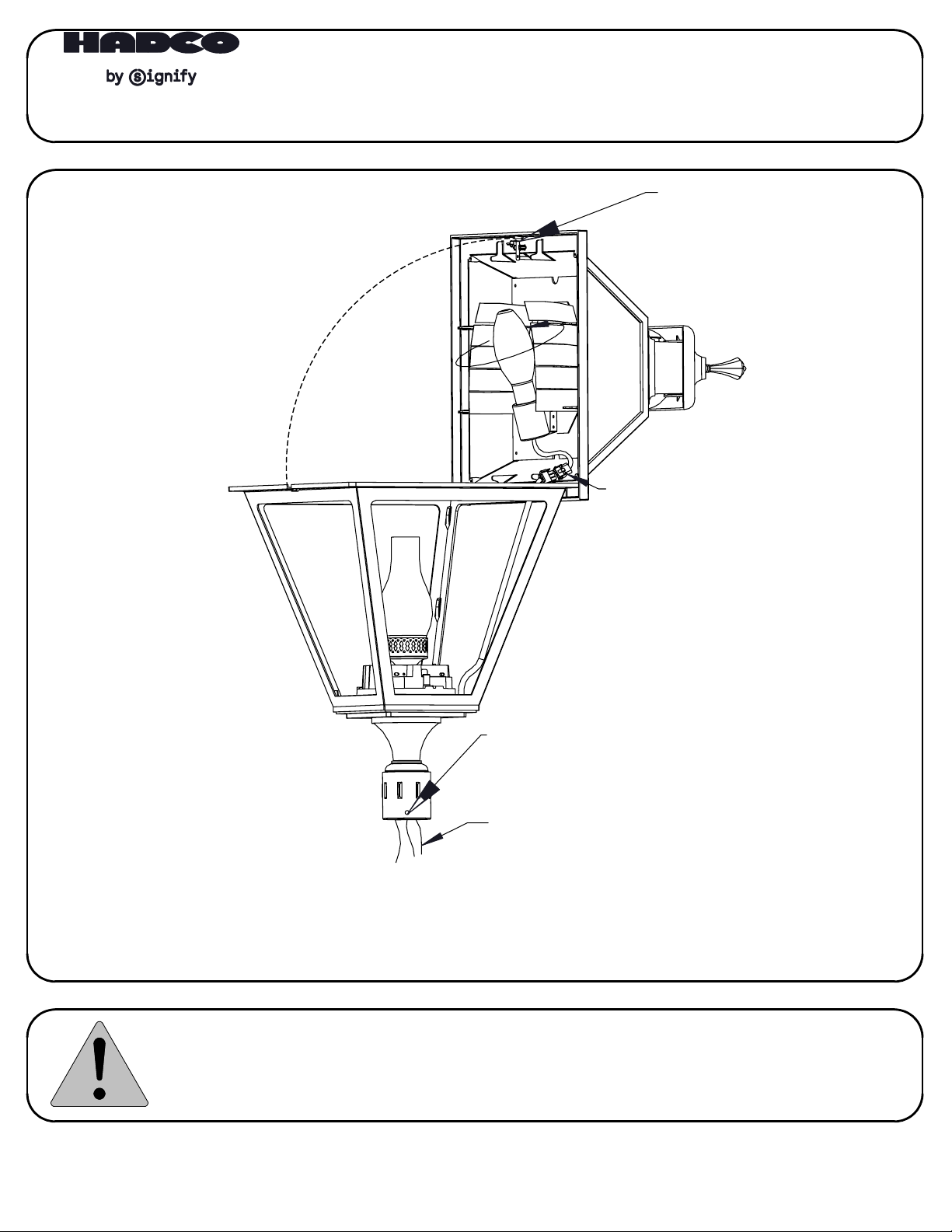
INSTALLATION INSTRUCTIONS:
V671 SERIES FIXTURES
SPRING CLIP
YELLOW DISCONNECTS
CAUTION
1. The electrical power must be disconnected from the fixture and pole before installing, servicing, or
relamping the fixture.
2. These directions must be read carefully and adhered to. Failure to do so may result in injury, damage to
the fixture, and voiding the warranty.
32001402, revision F
5/16-18 SET SCREW
USE 5/32 ALLEN WRENCH
SUPPLY WIRES
This fixture is intended for installation in accordance with the National Electrical Code and local code
specifications. Failure to adhere to these codes and instructions may result in serious injury and/or damage
to the ballast and void the warranty. These instructions do not purport to cover all details or variations in
equipment, nor to provide for every possible contingency related to installation, operation, maintenance,
or mounting situation. Should specific problems occur that are not addressed by these instructions, contact
your Sales Representative or distributor for assistance. Retain these instructions for future reference.
page 1 of 3
Page 2

TOOLS REQUIRED FOR INSTALLATION
1. 5/32" Allen Wrench
2. Screw Driver [#8-10, slotted type]
3. Screw Driver [phillips type]
4. Wire connectors for appropriate wire
INSTALLATION
WARNING - The power MUST be turned off prior to proceeding. Read these instructions carefully.
If any problems are encountered that are not covered in these instructions, contact Hadco
for assistance.
STEP 1: WIRING
1.1 Use wire nuts to connect incoming power supply wires to the fixture supply wires.
1.2 Provide a suitable strain relief for wiring.
STEP 2: MOUNTING
2.1 Mount the housing onto a 3" diameter post shaft or tenon.
2.2 Use the post fitter's 5/16-18 set screws, supplied in the fixture, to secure the
housing to the post shaft or tenon.
STEP 3: OPEN ROOF
3.1 Release the spring clip that secures the roof [see FIG. 1 on page 1].
3.2 Swing roof open to access lamp compartment.
STEP 4: LAMPING
4.1 Install the correct lamp based upon the lamp label next to the socket.
4.2 Clean installed lamp of all dirt and body oils.
4.3 Type III House-side Shield option ONLY. (Available for refractor panels only.)
* Rotate the reflector shield assembly around the socket to the correct orientation.
** Note: the reflector is the house side.
STEP 5: Close roof and secure with spring clip.
* Verify that spring clip snaps back into place and secures roof.
STEP 6: Connect power and test the fixture for proper operation.
STEP 7: After the installation is complete, deliver this manual to the owner.
LAMP REPLACEMENT
NOTE: It is a good idea to clean the fixture each time you relamp. Avoid using harsh solvents
or abrasives.
STEP 1: Release spring clip that secures the hinged roof. Open roof [see Fig. 1 on page 1].
STEP 2: Remove the old lamp and dispose of it in accordance with local codes and regulations.
STEP 3: Install a new lamp, referring to the lamp label next to the socket to ensure using the
correct type.
STEP 4: Clean installed lamp of all dirt and body oils.
STEP 5: Close the roof and secure.
* Verify that the spring clip snaps back into place.
TWIST-LOCK RECEPTACLE INSTALLATION / REPLACEMENT
NOTE: DECORATIVE VENT CAP is keyed to MOUNTING PLATE to ensure mounting in one direction
so that PHOTO CELL is properly oriented with PHOTO CELL LENSE.
STEP 1. Pull DECORATIVE VENT CAP from ROOF.
STEP 2. Ensure TWIST-LOCK RECEPTACLE is facing northward, if it is not facing northward the
following two adjustments could be made;
2.1 TWIST-LOCK RECEPACLE can be repositioned in 90~ increments by removing
and reinstalling the two MOUNTING SCREWS. Ensure MOUNTING PLATE & TWIST-LOCK
RECEPTACLE are rotated in unison.
2.2 Fixture could also be rotated on top of pole.
STEP 3. Install PHOTO CELL into TWIST-LOCK RECEPTACLE.
STEP 4. Reposition DECORATIVE VENT CAP and MOUNTING CLIPS into slots of the MOUNTING PLATE.
* Varify that the PHOTO CELL LENS is at the same location as the PHOTO CELL EYE.
STEP 5. Press DECORATIVE VENT CAP firmly into place.
32001402, revision F
page 2 of 3
Page 3

FIG. 3
PHOTOCELL LENS
TWIST-LOCK
RECEPTACLE
NORTH INDICATOR
DECORATIVE VENT CAP
PHOTO CELL
(BY OTHERS)
MOUNTING SCREWS
MOUNTING PLATE
DISCLAIMER
While we believe these instructions to be accurate at the time of publication, Hadco reserves the right to make
changes to this fixture and/or components. The contractor should follow local and National Electrical Codes
where required. For any further information please contact Hadco customer service.
32001402, revision F
page 3 of 3
 Loading...