

Page 1
INSTALLATION INSTRUCTIONS:
Signify North America Corporation Signify Canada Ltd.
200 Franklin Square Drive 281 Hillmount Road,
Somerset, NJ 08873 Markham, ON, Canada L6C 2S3
Telephone 855-486-2216 Telephone 800-668-9008
Safety, Warnings and Suggestions
1
2
9
10
should be taken not to position fixtures in locations where bare skin can come into contact with the potentially high
Care
temperatures on the lens.
3
4
5
6
7
8
sure that electrical power is disconnected before any work in performed.
Make
wiring and installation should meet local, state and national electrical codes. This will help prevent wire connector
All
corrosion due to water penetration from conduit.
correct lamp type and wattage per lamp label.
Install
gaskets and sealing surfaces must be kept clean during installation.
All
Check
that the inside of the housing is free of debris of any kind. This can obstruct the flow of air and
increase the temperature of the lens surface.
Check
that the gap between the lens ring and the casting is clear of any obtruction. Clean
installing fixtures in locations where water collects and stands for long periods.
Avoid
if required. Debris can obstruct the flow of air and increase the temperature on the lens surface.
a rule of thumb, the higher the fixture is mounted above grade potential problems such as foliage over growth or
As
water, mud etc. collecting on lens are reduced.
condensation, built up during installation, is visible on the lens it is recommended that the fixture be turned on before
If
the lens ring is replaced on the fixture for approximately 30 minutes. This should allow the condensation to be exhausted.
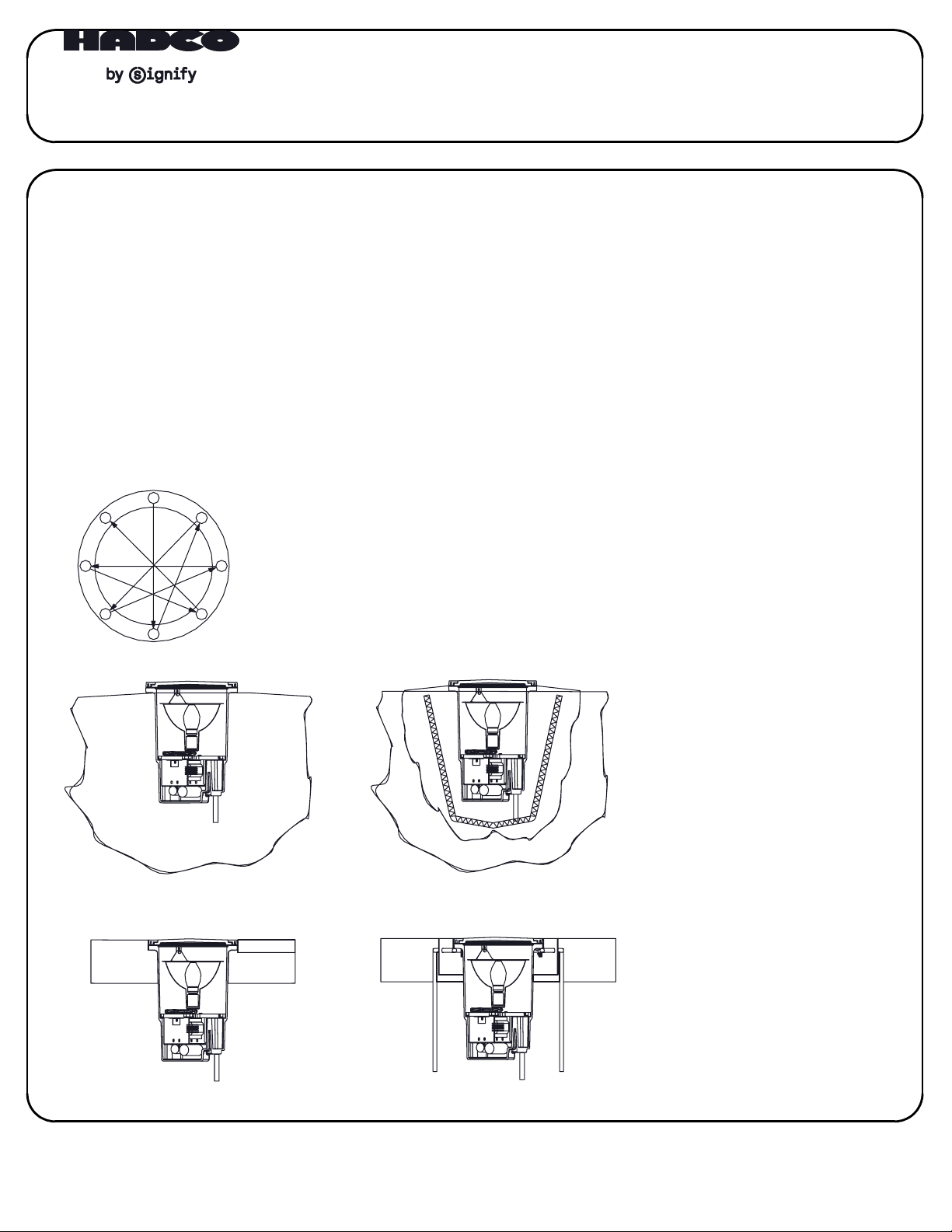
Mount fixture as high above grade as
1
8
6 5
4
2
3
7
SL-43 In Soil
Use several
rotations of
the following
sequence to
tighten the
lens ring socket
head cap screws
to 50 in/lbs.
possible to prevent debris and water
standing on fixture surface.
Create an isolation barrier around
the fixture to prevent rocks and
foilage from interfering with light output.
Add drainage media below and around
fixture to prevent standing water.
SL-43 In Soil with Concrete Base
and Trim Ring
Concrete
Paver/Marble
Use reinforcement
where necessary to
prevent concrete
cracking.
SL-43 In Concrete with Trim Ring
SL-43 In Concrete with Grout Mask
and Trim Ring
SL-43
1. Prepare the site with adequate
excavation to install fixtures.
Drainage media below fixture will
enhance installation.
2. Remove lens ring and lens with
gasket,
"D" shaped splice box cover plate
and gasket.
3. Connect conduit to the 3/4" NPT
openings in the splice compartment
at the bottom of the fixture, using
the appropriate thread sealing
compound.
4. Position fixture so it is flush or just
above the installation area grade
and orient the fixture with regard to
architectural requirements to obtain
the appropriate accent.
5. Make power and ground connections
using provided waterproff wire nuts.
It is recommended that RTV silicone or
other re-enterable water sealing
compound be used to seal the
conduit entry points.
6. Reinstall "D" shaped splice box cover
plate and gasket ensuring that all
(4) screws are securely tightened.
Reinstall reflector assembly, install
lamp
7. Install lens ring and lens with gasket
IMPORTANT! A CRISS CROSS PATTERN
IS REQUIRED TO ENSURE THAT A GOOD
COMPRESSION SEAL IS MADE.
If this is not accomplished, the fixture
could leak and be damaged.
Tighten socket head cap screws
gradually using multiple tightening
steps to 50 in/lbs.
4
8
and make aiming adjustments.
1
2,3
reflector assembly and
Tighten to 15 ft-lbs. max.
5
7
4
4
32A41398, revision C
page 1 of 2
Page 2
INSTALLATION INSTRUCTIONS:
SL-43 (LED VERSION ONLY)
FOLLOW ALL SAFETY PRECAUTIONS AND SITE PREPERATIONS PER PAGE 1 OF THESE INSTALLATION INSTRUCTIONS.
!!
1. Remove lens ring and lens with gasket.
2. Remove foam packing around heatsink used for shipping and discard appropriately.
3. Remove heatsink/ring assembly and "D" shaped splice box cover plate.
4. Connect conduit to the 3/4" NPT openings in the splice compartment at the bottom of the fixture using the appropriate thread sealing
compound.
5. Connect white (neutral) supply wire to white fixture wire, black (hot) supply wire to black fixture wire, and greeen (ground) supply wire
to green fixture wire using provided waterproof wire nuts. It is recommended that RTV Silicone or other re-enterable water sealing
compound be used to seal the conduit entry points.
*Control wires (gray and purple) are crimped to prevent cross wiring. If using a dimming device, cut ends, strip and connect.
- See approved dimmer list per Xitanium driver X1036C100V048DNM1 datatsheet.
- Consider limitation/impact of long wire runs when installing 0-10V dimming systems.
*Input voltage (VAC): 120-277v auto sensing, 50 or 60Hz
*Fixture load: 34W max.
6. Reinstall "D" shaped splice box cover plate ensuring that all four (4) screws are securely tightened.
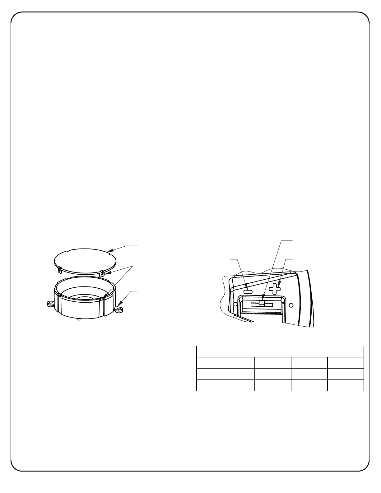
7. Fixture is pre-installed with "Medium Flood" optic lens from factory. To replace with "Narrow Flood" or "Wide Flood" optics, pop optic lens
off reflector by using fingernails or screw driver at the (4) tabs.
Narrow flood lens (20 deg)
Medium flood lens (36 deg)
Wide flood lens (65 deg)
Align new optic lens with tabs and push onto reflector until all four locations snap into place.
8. Adjust lumen output switch by sliding the switch to the desired setting. There are (5) different settings ranging from 9.5W to 34W.
See chart below for approximate lumen values. Heatsink has a "+" and "-" symbol to illustrate wattage level.
9. Reinstall heatsink/ring assembly. Angle heatsink in orientation desired (typically vertically straight).
10. Reinstall lens ring and lens with gasket. Tighten socket head cap screws gradually using multiple tighening steps
(see pictorial of pattern on page 1).
IMPORTANT! A CRISS CROSS PATTERN IS REQUIRED TO ENSURE THAT A GOOD COMPRESSION SEAL IS MADE.
If this is not accomplished, the fixture could leak and be damaged.
Tighten to 15 ft-lbs. max.
- supplied in bag, marked along edge of lens with "P".
- pre-installed, marked along edge of lens with "I".
- supplied in bag, marked along edge of lens with "S".
OPTIC LENS
(3 OPTIONS)
ALIGN TAB
WITH NOTCH
MIN. (9.5W) SETTING
to 50in/lbs.
OUTPUT SWITCH
(NOMINAL 20W SHOWN)
MAX. (35W) SETTING
!!
REFLECTOR
(DO NOT REMOVE)
REPLACEMENT OPTIONS:
1. Driver - includes driver and mounting screws.
2. Optic lens kit - includes [3] optic lenses (reflector not included)
3. Switch kit - includes switch and mounting screws.
DRIVER REPLACEMENT INSTRUCTIONS:
1. Remove lens ring and lens with gasket.
2. Remove heatsink/ring assembly and driver box cover plate.
3. Remove driver screws and detach driver.
4. Disconnect existing driver wires from connectors and replace driver.
See wiring diagram for Xitanium driver X1036C100V048DNM1.
*Reconnect wires to surge protector (SP1) if applicable.
5. Reattach driver to cover.
6. Reassemble remaining items per installation instructions above (see item numbers 8-10).
Beam/Switch output
Medium Flood (3000K)
Medium Flood (4000K)
Lumen Output Table (Clear Glass Lens Option)
Factory pre-set at this level.
*
9.5W (min)
1030 2055 3075
1095 2185 3269
* 20W (nom)
34W (max)
32A41398, revision C
page 2 of 2
 Loading...