

Page 1
Reliable SR
technology for
connected
LED applications
LED Drivers
Design-in Guide
Page 2

Contents
Introduction to this guide 3
Information or support 3
Application note 3
Warnings and instructions 4
Safety warnings and installation instructions 4
Introduction to Advance Xitanium
SR bridge 5
Xitanium SR bridge 5
Xitanium SR bridge versions 5
Programmable interface 5
SimpleSet technology 5
SR bridge wiring diagram 5
Features of Xitanium SR bridge 6
Wide mains input range 6
Switchable output using zero
crossing detection 6
Sensor ready (SR) interface 6
Energy metering 6
MultiOne/SimpleSet congurable features 6
Sensor ready (SR) interface 7
Sensor ready interface 7
Typical examples 8
Digital communication 9
Other considerations for SR interface 9
SR bridge use cases 10
Basic SR bridge use case 10
347V SR bridge use case 1 1
SR bridge dimming curve and dimming range 1 1
SR bridge fault detection use case 1 1
SR bridge class room with occupancy/
daylight harvesting use case 12
SR bridge hallway use case 13
Mechanical design-in 14
Form factors 14
Thermal management 15
Introduction 15
Temperature case point 15
Electrical design-in 16
Inrush current 16
Surge protection 16
Leakage current 17
Electromagnetic compatibility (EMC) 17
Electrical isolation 17
Disclaimer 18
Notes 19
2 Advance Light ing
Page 3
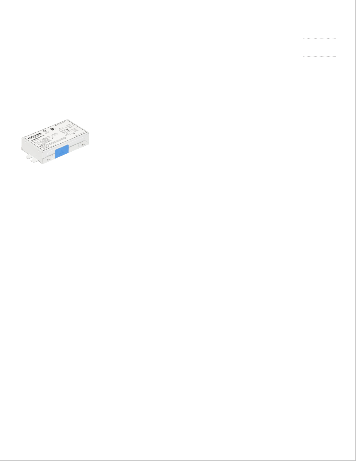
Introduction to this guide
Figure 1. Advance Xitan ium SR br idge.
Xitanium SR Bridge
Design-in Guide
Intro duc tion
to This Gu ide
Thank you for choosing the Advance Xitanium sensor ready
bridge (SRB). In this guide you will nd the information
needed to integrate SRB devices into an LED luminaire
or LED system.
Information or support
For further information or support please consult your local Advance oce or visit:
• Xitanium SR bridges or SR drivers: www.philips.com/xitaniumsr/na
• OEM general info: www.philips.com/oemna
• EasySense: www.philips.com/easysense
Application note
The Advance Xitanium SR bridge allows existing 0-10V dimming systems to become
part of wireless connected lighting systems for indoor lighting such as oces,
public buildings, industrial applications and retail environments.
3
Page 4
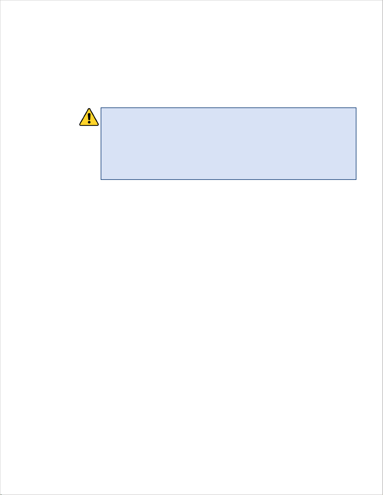
Warnings and instructions
Warnings
• Avoid touching live parts!
• Do not use SR bridge and connected driver(s) with damaged housing
and/or connectors!
• Do not use SR bridge and connected driver(s) with damaged wiring!
Safety warnings and installation instructions
• Do not use damaged products.
• Do not short SR bridge output wires.
• SR bridge output wire is a live mains part when switched on.
• The luminaire manufacturer is responsible for complete luminaire design and must
comply with all relevant safety standards.
• The SR bridge is suitable for built-in use only and must not be exposed to the elements
such as snow, water and ice or to any chemical agent that can be expected to have an
adverse eect on the driver (e.g., corrosive environments). It is the responsibility of both
luminaire manufacturer and installer to prevent exposure. The SR bridge specied for UL
damp and dry locations.
• Do not service the SR bridge and connected driver(s) when the mains voltage is
connected; this includes connecting or disconnecting the loads.
• SR bridge and connected driver(s) must be installed in accordance with national and
local electrical codes.
• Proper earth and/or equipotential connections are required whenever possible
or applicable.
4 Advance Li ghtin g
Page 5
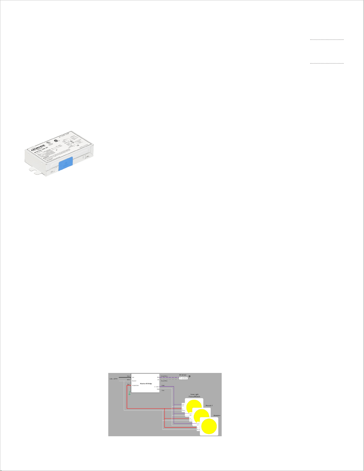
Introduction to Advance
Advance Xitanium SR bridge
Figure 2. Advance Xitan ium SR br idge.
Xitanium SR Bridge
Design-in Guide
Intro duc ti on to
Advance Xitanium
SR Bridge
Xitanium SR bridge
The Advance Xitanium SR bridge is designed to connect existing or new 0-10V dimming
indoor lighting systems to SR (wireless) connected systems. Applications include oces,
public buildings, industrial applications and retail environments.
With Xitanium SR functionality, exibility in luminaire design is assured, and with the SR
interface it is simpler than ever to connect to SR certied sensors.
Xitanium SR bridge versions
The Xitanium SR bridge described in this guide is available in two versions; a –BS version
with mounting studs to mount the box to an existing (downlight) xture mounting plate and
a –LD version to be mounted inside luminaires.
Detailed specications can be found in the Xitanium SR bridge datasheets, which can be
downloaded at www.philips.com/xitaniumsr/na.
Programmable interface
The Xitanium SR bridges are programmable. Some features and parameters can be set via
the SR Interface or SimpleSet technology using Advance MultiOne Congurator software.
SimpleSet technology
Advance SimpleSet NFC wireless programming technology allows luminaire manufacturers
to quickly and easily program the Xitanium SR bridge during the manufacturing process,
without a connection to mains power, oering great exibility.
For more information on MultiOne or SimpleSet technology, please visit www.philips.com/
multione or contact your local Advance representative.
SR bridge wiring diagram
A typical application for the Xitanium SR bridge is to connect the SR bridge to one or more
0-10V (LED) drivers and an SR-certied device (see Figure 3).
Figure 3 . Xitan ium SR br idge w irin g diagram.
5
Page 6

Features of Xitanium SR bridge
Wide mains input range
The Advance Xitanium SR bridge can operate on a wide range of mains input voltages from
120Vac – 347Vac.
Switchable output using zero crossing detection
The output of the Xitanium SR bridge can be switched on/o via integrated relay switching
with advanced zero crossing technology. This allows for higher loads to be switched on/o
with high reliability.
Sensor ready (SR) interface
The Xitanium SR bridge features a digital interface (SR interface) to enable direct
connection to any suitable SR-certied RF sensor.
Energy metering
The Xitanium SR bridge has built-in energy/power measurement capability.
MultiOne/SimpleSet congurable features
6 Advance Ligh ting
Note: These features are only supported from MultiOne 3.4 onward. Please also refer to the
“Advance MultiOne Congurator” user manual that can be accessed from the Help menu
inside the MultiOne software, for more information.
Feature Description of the feature Notes and examples
0-10V / 1 -10V This feature gives the OEM the ability to match the
0-10V (or 1-10V) dimming curve of the connected
driver to the correct translation of the DALI arc
power commands on the SR Bus.
DALI PSU DALI Power Supply. This feature can turn on/o
the build-in SR Power Supply
LFIT Load Fault Indicator Thresholds. This feature
allows the OEM to set a threshold to indicate one
(or more) lights have failed and set the DALI lamp
failure detection properly.
Min dim level Minimum dim level. This feature can be used to
set the minimum (DALI) dim level of the SR Bridge
to match the minimum dim level of the connec ted
0-10V d ri ve r(s).
OEM
Traceability
RSO Relay Switched Output. This feature can be used
Table 1. SR bridge MultiOne/SimpleSet congurable features.
OEM Traceability. This feature allows the OEM to
store a GTIN and identication number and some
additional information that could be used for
Traceability or Asset Management.
to enable/disable the relay of the SR Bridge.
Four xed curves (1-10V curved, 1- 8V linear, 1-9V
linear, 1-8V logarithm) or User specied can be
selected. 1-8V linear is default to match most
Advance Xitanium LED drivers.
By default the SR DALI PSU is turned on
(Enabled).
Typical sett ing corresponds to maximum p ower
of all drivers connected minus one so that if one
driver fails it w ill be detected.
Default setting is 1%. But if the connected driver
can only dim down to 10%, the DALI dim level of
the SR Bridge can be also set to 10% matching
the DALI dim curve to the 1-8V dimming cur ve of
the driver. Any DALI arc level command for < 10%
will result in a 1V output on the 0-10V output of
the SR Bridge.
The GTIN and ID are part of standard DALI.
The additional information can be up to 42
characters long.
In cases where the lights should not be turned o
when the DALI O command is used, the “Always
stays closed” button should be checked.
Page 7

Sensor ready (SR) interface
Figure 4 . Typical VI-curve SR bus
power supply.
Xitanium SR Bridge
Design-in Guide
Sensor Ready (SR)
Interfa ce
Sensor ready interface
The Advance Xitanium LED SR bridge features a digital SR interface to enable direct
connection to any suitable SR-certied RF sensor.
The simple two-wire SR interface supports these key functions:
• Switchable built-in SR bus power supply to provide power to the connected control
device (e.g., an RF module or a CMS controller)
• Two-way digital communication between the SR bridge and control device, using
standard DALI 2.0 protocol
• Standard DALI dimming, ON/OFF and control functions
• Power and energy reporting utilizing the power monitoring integrated in the SR bridge
• Diagnostic information
Built-in SR bus power supply
The SR bridge has the ability to supply the SR bus with a built-in power supply that can
be turned ON/OFF. By default the power supply is turned on and ready to be used with an
external control device (e.g., RF sensor).
This should in principle be turned o if used in DALI networks with multiple drivers to avoid
incorrect polarity, which can lead to very high currents on the DALI bus. However, we do not
recommend to use this SR bridge in a wired DALI network.
The internal power supply can be turned ON/OFF with the MultiOne conguration software
using the SimpleSet tool or the SR interface (DALI) tool.
The built-in SR supply is capable of delivering a minimum current of 52 mA (ISR) to the SR
bus and the connected device(s).
The built-in SR supply will never supply more than 60mA (ISR_MAX).
The SR bus voltage will be between 12V and 20V depending on the connected device load
and the amount of SR supplies put in parallel. See Figure 4 for the typical VI curve for one
SR supply.
When the internal SR supply is switched OFF, the SR bridge will extract a maximum of 2 mA
from the SR bus (like standard DALI gear).
7
Page 8

Control device(s)
• Most control devices intended to be used in an SR system will be powered from the SR
bus.
• When communication is present on the SR bus, the bus gets pulled down by the data
packages. This reduces the average current available for the power consuming control
device. When communicating the average available current can drop approximately
50%. This should be taken into account when designing the control device.
• The extracted peak current (ISR_EXTRACTED) should be limited by the control device.
Rules for building an SR system
• Respect SR bus polarity when more than one SR supply is connected in parallel.
• The total maximum SR bus current (ISR_MAX_TOTAL) must be ≤250 mA. This current
can be determined by adding ISR_MAX of all SR supplies. As a consequence, a
maximum of four SR supplies can be connected in parallel. The total current delivered
to the SR bus (ISR_DELIVERED) can be determined by adding ISR of all SR supplies.
• The total current extracted from the SR bus (ISR_ EXTRACTED) can be determined by
adding up consuming devices like SR drivers with switched OFF SR supply, other DALI
gear and control devices.
• To guarantee good communication, a margin of 8 mA is needed to drive the SR bus
itself (ISR_MARGIN).
• The following rule should be respected:
ISR_EXTRACTED + ISR_MARGIN ≤ ISR_DELIVERED.
Caution
• When the above rules are not taken into account, communication cannot be
guaranteed and damage to components may occur.
Typical examples
One SR bridge is connected to a control device. The internal SR supply of this bridge is
switched ON. The specication of the control device states that the extracted peak current
is 40 mA. Will this SR system have good communication?
• One SR supply is involved, so BUS polarity is not an issue.
• ISR_MAX_TOTAL = 60 mA. This is ≤250 mA.
• ISR_DELIVERED = 52 mA
• ISR_EXTRACTED = 40 mA
• ISR_MARGIN = 8 mA
• 40 + 8 mA ≤52 mA
8 Advance Lig hting
Page 9

Xitanium SR Bridge
Design-in Guide
Sensor Ready (SR)
Interfa ce
Is it allowed to add an SR bridge with switched OFF SR supply to this SR system?
• Yes, an SR driver with switched OFF SR supply extracts 2 mA from the SR bus.
• ISR_EXTRACTED = 40 + 2 = 42 mA
• 42 + 8 mA ≤52 mA
Can this SR supply also be switched on?
• Yes, but you should check the polarity of both SR supplies.
• ISR_TOTAL = 2 * 60 = 120 mA. This is ≤250 mA.
Digital communication
Dimming is possible through the standard digital interface based on DALI 2.0 (IEC 62386
101, 102 Ed2.0). Dimming range is 1%-100%. Dimming curves can be either logarithmic or
linear (see Figures 5 and 6).
• Note that the output current at 1% and 100% level is determined by the
connected driver.
• The SR bridge has built-in energy measurement capability and can report energy and
actual power consumption. Accuracy of power measurement is higher of following
two values: 0.5W or +/-4 % measured input power. This feature stores parameters in
the non-volatile memory bank provision specied in the DALI 2.0 standard and the
SR Certied specication.
• The SR bridge also supports many diagnostic features/parameters, which can be
accessed via the SR interface, as per SR Certied specication.
• Although the SR interface supports DALI commands, it is not a DALI interface as such
since the interface is polarity-sensitive. We do not advise use of the SR bridge in wired
DALI networks.
Other considerations for SR interface
• Length of wiring: using 18AWG (0.8 mm2), the maximum length of the SR wiring, when
used for DALI communication, should not exceed 50ft (15m).
• The SR control interface terminals are Class 2 as per UL.
DALI Linear Dimming Cur veDALI Logarithmic Dimming Curve
Figure 5. DALI logarithmic dimming curve. Figure 6. DALI line ar dimm ing cur ve.
9
Page 10

SR bridge use cases
Basic SR bridge use case
The basic use case for the SR bridge is to connect one or more 0-10V dimming drivers and
an SR-certied device to the SR bridge as shown in Figure 7.
Figure 7. Bas ic Xitanium SR b ridg e use ca se.
By default, the SR bridge dimming curve is set to linear and the range is 1 – 8V and is meant
to work with standard 0-10V drivers with linear dimming curve and 1-8V range. If other
drivers are used it is possible that the dimming curves will not match.
The maximum load that the SR bridge can handle depends on the mains input voltage.
The maximum allowed loads are given in the SR bridge datasheet.
10 Advance Lighting
Page 11

Xitanium SR Bridge
Design-in Guide
SR Brid ge Use
Cases
347V SR bridge use case
The SR bridge can handle up to 347V mains input. For basic 347V operation the wiring
diagram is similar as for 120/277V operation. Figure 8 shows how a SR bridge can be
connected to a 347V 0-10V LED driver and an SR sensor.
Figure 8 . Basi c Xitan ium SR br idge 3 47V operati on.
SR bridge dimming curve and dimming range
The SR bridge dimming curve and dimming range can be programmed using the MultiOne
Congurator or SimpleSet. By default, the dimming curve is set for DALI linear and the
dimming range is set at 1 – 8V.
The dimming curve can be programmed as either being (DALI) logarithmic or linear.
To meet the DALI logarithmic or linear curve, the physical minimum dimming level and
dimming curve of the connected 0-10V driver should be congured correctly in the SR
bridge using the MultiOne Congurator or SimpleSet.
If you are using a Advance 0-10V driver, you can select the dimming curve and physical
minimum dimming level that are used in that driver. However, if you are using a driver
from another manufacturer, you possibly have to customize/congure the dimming curve
vs. dim percentage and physical minimum dimming level for that driver.
The SR bridge dimming range can be programmed in 19 steps. For each step a voltage
value and dimming percentage need to be set.
The voltage values can be from 0 – 10. The dimming percentage values need to be
within 1 – 100%.
SR bridge fault detection use case
The SR bridge is measuring the power/energy consumed of the connected loads constantly.
This feature can be used to monitor the connected load and determine if a portion of the
load has failed. During normal operation (at full output) the connected load/drivers draw
a certain amount of power. If one or more connected loads fail, the power consumption
will be reduced. The SR bridge has the capability to set the DALI Lamp Failure ag based
on a threshold that can be programmed in the SR Bridge indicating that the load has been
reduced. The fault detection accuracy depends on the trigger point and minimum detection
dim level, which can be congured by MultiOne.
11
Page 12

For example if (10) 50W drivers are connected a SR Bridge each with a max input power of
50W for a DALI Arc Power command of 254 (full output) then to be able to detect the failure
of (1) driver/LED load, the threshold would be set at (9x50=) 450W. The SR Bridge would
report/set DALI Lamp Failure when the power measured by the SR Bridge becomes less
than 450W. Note, that this power level must be scaled by the SR Bridge if the Arc Power
command is other than 254.
In this case with lights set at 50% Arc Power then the expected power would be 250W and
the SR Bridge would report/set DALI Lamp Failure when the power is less than 225W.
SR bridge class room with occupancy/daylight harvesting use case
Existing class rooms using a 0-10V dimming system can easily be retrotted with a SR bridge
and certied SR sensors using occupancy/daylight harvesting to achieve maximum energy
eciency/savings and to create a connected lighting system. A typical (small) class room has
several rows of dimmable lights controlled by a switch/dimmer near the entrance door.
For this use case we are going to assume a small class room with windows on one side
having 4 rows of 5 lights each. All (0-10V dimmable) lights are controlled by a switch/
dimmer near the entrance door (see Figure 9).
12 Advance Lighting
Figure 9. Typica l small Class ro om wit h 0-10V dimming system.
To make it a occupancy/daylight harvesting connected lighting system we are going to use
2 SR bridges each with a SR certied sensor (like the Advance EasySense SNS series of
sensors). The rst SR bridge and sensor gets connected to the rst 3 rows of the lights with
the (occupancy) sensor placed near the entrance door. The second SR bridge and (daylight
harvesting) sensor gets connected to the last row of lights closest to the windows (see
Figure 10) with the (occupancy/daylight) sensor placed near the window. Retrotting the
existing 0-10V dimming system with the SR Bridge solution does not take much installation
work. The SR Bridges get mounted in between the mains feed and the rst driver in each
section. The dimming wires get disconnected from the existing dimmer and rerouted to
the SR Bridges. All other mains and dimming connections between the other drivers remain
the same.
Page 13

Xitanium SR Bridge
Design-in Guide
SR Brid ge Use
Cases
Figure 10. Small Class roo m retro tted w ith SR Br idge s olution.
SR bridge hallway use case
Hallways/long corridors are another area that can easily be retrotted with SR Bridge and
SR sensor to achieve maximum energy eciency/savings and to create a connected lighting
system. In a typical Hallway 0-10V dimming system the lights can usually be turned on/o at
both ends (see Figure 11).
Figure 11 . Typical Hallw ay 0-10V dimming system.
With the SR Bridge and SR sensor we can now add occupancy detection and create a
connected lighting system that not only can dim up/down but turn on/o the lights where
needed for maximum energy savings. In our use case example we are going to use 2 SR
Bridges and 2 SR occupancy sensors since we assume the hallway is too long to be covered
by one sensor only (contact the sensor manufacturer for more detailed information for
coverage area/distance between sensors. For more detailed information on EasySense
sensors see the EasySense link listed in the introduction section.)
In this example the Hallway lights are going to be divided into 2 sections (one 4 lights and one
3 lights). A SR bridge and SR (occupancy) sensor get connected to each section (see Figure 12).
Figure 12. H allway ret rotted with SR Brid ge and SR s enso rs.
For this retrot installation the mains to the existing 0-10V drivers (on each) end have to
be re-routed to each SR bridge. And 2 sections of lights have to be created by cutting the
mains and dimming wires between 2 of the lights.
13
Page 14

Mechanical design-in
Form factors
The Advance Xitanium SR bridge is available in two dierent versions: model SRB-LD is
for mounting inside luminaires (see Figure 13) and model SRB-BS includes studs to easily
mount the SR bridge onto a mounting plate of a downlight xture (see Figure 14).
The specic dimensions can be found in the SR bridge datasheet.
It is highly recommended to mount the SR bridge by using all available mounting feet/studs
in order to achieve maximum mechanical robustness against shocks and vibration.
Mounting screw dimensions should be based on the specied xing hole diameter in the SR
bridge datasheet. Oversized and undersized screws should not be used in order to prevent
damage to the mounting feet or loose mounting.
Please allow for sucient free space around the SimpleSet antenna (blue areas as shown
in Figure 13 and 14) if the SR bridge is to be congured after mounting in the luminaire. The
minimum recommended space is dependent on the type of SimpleSet conguration tool.
Using the tool as shown in Figure 15 (Feig Electronic Desktop Reader ID CPR30-USB), the
minimum distance is 19 mm (+/-1mm).
14 Advance Lighting
Figure 13. SRB-LD version for luminaire mounting.
Figure 15 . Feig Elec tronic ID CPR30-USB SimpleSet i nterf ace tool.
Figure 14 . SRB-BS version to mount to (downlig ht) xture
mounting plate.
Page 15

Thermal management
Introduction
The following section covers the critical thermal management point to facilitate design-in.
Taking thermal considerations into account will ensure optimal performance and lifetime
of the system. The maximum case temperature (Tc max) of the SR bridge should not be
exceeded. It is mandatory to keep the SR bridge Tc max within specication to meet SR
bridge lifetime and failure rate specications. Please refer to the product datasheet for
specic values. Advance Xitanium SR bridges are designed to provide a lifetime of up to
50,000 hours at the specied Tc max.
Temperature case point
To achieve optimal lifetime and reliability, it is critical that the temperature of the
components in the SR bridge remains within their rating. During design, all precautions
are taken to ensure that the internal components are at the lowest possible temperatures.
Xitanium SR Bridge
Design-in Guide
Thermal
Management
Initial thermal analysis is performed via IR scans at room temperature to identify the
hottest components of the SR bridge. Subsequently, detailed temperature measurements
of the critical components are performed under various input/output conditions at worst
case operating temperatures.
The temperature measurements are then correlated to a Tcase (Tc) point on the SR bridge
as shown in Figure 16. Tc temperature is a proxy for the temperatures of the critical internal
SR bridge components.
The location of the Tc point is identied on the product label (Figure 17).
Note:
The specied Tc max of the SR bridge must NEVER be exceeded. In order to ensure
accurate Tc test results, the case temperature should not vary by more than 1°C for a period
of at least 30 minutes after a stable temperature has been achieved. Tc point should not
be obstructed when mounted in the luminaire/enclosure.
Figure 16. Schematic representation of internal
therm al paths to the SR br idge Tc poin t.
Figure 17. Prod uct label
indicating Tc point.
15
Page 16

Electrical design-in
Inrush current
Inrush current refers to the brief high input current that ows into a device during the
moment of connection to mains; see Figure 18. Typically, the amplitude is much greater
than the steady-state input current.
Advance Xitanium products meet the inrush specication values per NEMA 410.
The SR bridge uses advanced “zero-crossing” technology by turning on the connected load
only when the mains voltage is near the zero crossing. This reduces the inrush current of
the connected load(s) to a minimum.
The peak and duration values are given in the individual product datasheet. It should be
noted that the inrush current measurement given in the datasheet is the absolute worst
case value.
What does inrush current do? High inrush currents can cause circuit breakers or fuses to
open if not designed to handle this current. It can limit how many drivers can be connected
to a circuit breaker (CB) or fuse. In case of the SR bridge, it limits how many drivers can be
connected to the SR bridge.
Surge protection
The Advance Xitanium SR bridge has limited built-in surge protection (in accordance with
IEEE/ANSIC62.41.2 Transient Surge Requirements). The datasheet gives the protection level
of the SR bridge. A specication of 2.5kV means that the SR bridge is tested to
withstand 2.5kV line transient for 100kHz Ring wave with 30 Ohms source impedance.
The SR bridges are tested with the above waveform for all line coupling modes (L to N,
L to PE, N to PE and L&N to PE).
In case the SR bridge is built into a luminaire, appropriate surge protection should be
designed into the luminaire to meet the specic category for meeting the Energy Star/
ANSI requirement.
Figure 18.Graphical representation of inrush current.
16 Advance Lighting
Page 17

Xitanium SR Bridge
Design-in Guide
Electrical
Design-in
Leakage current
The Advance Xitanium SR bridge is designed to meet leakage current requirements per
UL 916 standards. The specied maximum value is 0.75 mA RMS at 277V. The test is done
with the SR bridge alone. In a luminaire, leakage current may be higher since the LED load
introduces additional leakage capacitance. As such, precautions should be taken on the
luminaire level.
Electromagnetic compatibility (EMC)
The Xitanium LED SR bridge meets EMC requirements per FCC Title 47 Part 15 Class A. These
tests are conducted with a reference setup and the SR bridge mounted on a grounded
metal plate. To maintain good EMC performance at the luminaire level, the input, output
and dim wires should be kept as far apart as possible. The addition of ferrite beads in
series with the wires or coupling the wires through ferrite cores within the luminaire may
improve the overall EMC performance. However, selection of the type and characteristics
of the additional lter depends on what frequency components have to be damped and
by how much.
Electrical isolation
The Advance Xitanium SR bridge output is isolated from the primary (Class 2).
Isolation is also provided between all the electronic circuits and the chassis.
Xitanium bridges meet UL 916, and the output terminals have been qualied as
Class 2 circuit with UL1310 safety standards.
All of the wires in the Advance Xitanium SR bridges meet the UL1452 safety standards.
17
Page 18

Disclaimer
©2017 Advance Lighting Holding B.V. All rights reserved.
Note that the information provided in this document is subject to change.
This document is not an ocial testing certicate and cannot be used or construed
as a document authorizing or otherwise supporting an ocial release of a luminaire.
The user of this document remains at all times liable and responsible for any and all
required testing and approbation prior to the manufacture and sale of any luminaire.
The recommendations and other advice contained in this document, are provided
solely for informational purposes for internal evaluation by the user of this
document. Advance Lighting does not make and hereby expressly disclaims any
warranties or assurances whatsoever as to the accuracy, completeness, reliability,
content and/or quality of any recommendations and other advice contained in this
document, whether express or implied including, without limitation, any warranties
of satisfactory quality, tness for a particular purpose or non-infringement. Advance
Lighting has not investigated, and is under no obligation or duty to investigate, whether
the recommendations and other advice contained in this document are, or may be,
in conict with existing patents or any other intellectual property rights. The
recommendations and other advice contained herein are provided by Advance
Lighting on an “as is” basis, at the user’s sole risk and expense.
Specically mentioned products, materials and/or tools from third parties are
only indicative and reference to these products, materials and/or tools does not
necessarily mean they are endorsed by Advance Lighting. Advance Lighting gives no
warranties regarding these and assumes no legal liability or responsibility for any
loss or damage resulting from the use of the information thereto given here.
18 Advance Lighting
Page 19

Notes
Xitanium SR Bridge
Design-in Guide
Notes
19
Page 20

© 2019 Sig nif y Holding. A ll rig hts re served. The infor mation prov ided h erei n
is subject to change, without notice. Signify does not give any representation
or warranty a s to the accura cy or completenes s of the information i nclu ded
herei n and sh all not be liable for a ny action in re lian ce the reon. T he informat ion
prese ntedin t his document is not inten ded as a ny commercial of fer and does
notform p art of any quot atio n or contract , unle ss othe rwise agreed by S igni fy.
All tra dema rks are owned by Sign ify H oldi ng or th eir respective ow ners.
PAd-1704DG 02/19 www.signify.com/advance
Signify North America Corporation
200 Franklin Square Drive,
Somerset, N J 08873
Telephone 855-486-2216
Signify Canada Ltd.
281 Hillm ount Ro ad,
Markh am, ON , Cana da L6C 2S3
Telephone 800-668-9008
 Loading...