

Signet Pulse 2.200 LS Operation & Instruction Manual

Page 1 of 12 DocNo.DCP0001326 DSM 06/01/05 rev7
Features
The P2.200 LS amplifier contains two identical independent amplifier modules. Each has one Main and one
Aux. input. Routing logic allows the Main and Aux. to mix; this allows the monitoring tone to pass at all times
and the monitoring system to operate. If the PTT is operated, the Main input overrides the Aux.
Each module’s status is displayed on the front panel along with an output level bar graph and status
indicators. All sections of the amplifier and charger are constantly monitored for faults or abnormal operation:
1 The load monitoring checks the power absorbed by the loudspeaker load at 22 kHz and compares this
with the threshold and window levels set at installation. If the power drawn deviates outside the window a
fault is indicated on the front and rear of the unit and signalled to other equipment via the relevant fault
outputs.
2 If the impedance monitoring tone is not being received by the amplifier, both the Load Hi and Load Low
front LEDs light and the rear Tone Fail light shows.
3 Should either leg of the loudspeaker wiring short to system earth this will also light the Load Hi and Load
Low LEDs on the front panel, along with the Earth Fault LED on the rear.
4 Mains power status is also monitored, along with the internal fuses, to give a complete picture of the state
of the amplifier.
The load monitoring system also provides an output to drive a ‘hot swap’ automatic amplifier replacement
system, via the HSP port, on failure of the amplifier only. Should a load fail short or open circuit but the
amplifier is still OK, the hot swap output will not operate. This means that any loudspeakers that can be
driven will operate and leaves the hot swap amplifier available for use on another potential failure.
The output from each module is presented on a three-way socket and is fully floating. The standard output
voltages are 50V and 100V, allowing two modules to be connected in series to give 400W at 100V line.
The power supply has a 24 Vd.c. battery input and an onboard battery charger.
Technical Description
Amplifier Modules
The Aux. and Main line level inputs are de-balanced and pass via level controllers and an analogue switch
into a summing amplifier where they are mixed. If the contact input is asserted (470 ohms to ground) a logic
circuit disconnects the aux. input.
The protect circuit disconnects the output transformer when the voltage rails fall below 22 Volts, exceed 36
Volts, or when a d.c. offset is present on the output rails. The signal then passes through to the output stage,
which is a feed-forward current-mode bridge circuit and the output level meter monitors the level at this stage.
The output current is passed through the primary of the output transformer and through a low value outputsensing resistor. The output of the transformer is tapped at 50 and 100 Volts. If the 50 Volt taps are
connected in series the unit provides a single 400 Watt output at 100 V line.
Power Supply
A large capacitor reservoir provides a very smooth output, even under large current surges. Two separate
internal 10 Amp fused outputs connect to the two amplifier modules.
A separate low-current feed passes via the sleep enable selector link into the sleep timer section. Another
feed passes, via the Aux. on LED (this shows that the Aux. power is available on the rear connector) through
a 3 Amp fuse to the Aux. power connector. With mains voltage operation this unregulated output is at
approximately 32 Vd.c. When mains has failed, this output is connected to the battery and therefore operates
at battery voltage level.
A 27.6 Volt regulator is also taken off this line and used to charge external batteries via a 20 Amp fuse.
PSU and amplifier faults are returned into the monitoring circuit from both amplifiers, slugged to prevent false
faults being reported externally, and passed to the open collector fault outputs on the SIP port. A fourth open
collector output is normally set as OK (normally closed) and opens when any fault occurs.
Operation Instruction Manual
Pulse 2.200 LS Dual 200W 100V line Amplifier with Monitoring
Page 2 of 12 DocNo.DCP0001326 DSM 06/01/05 rev7
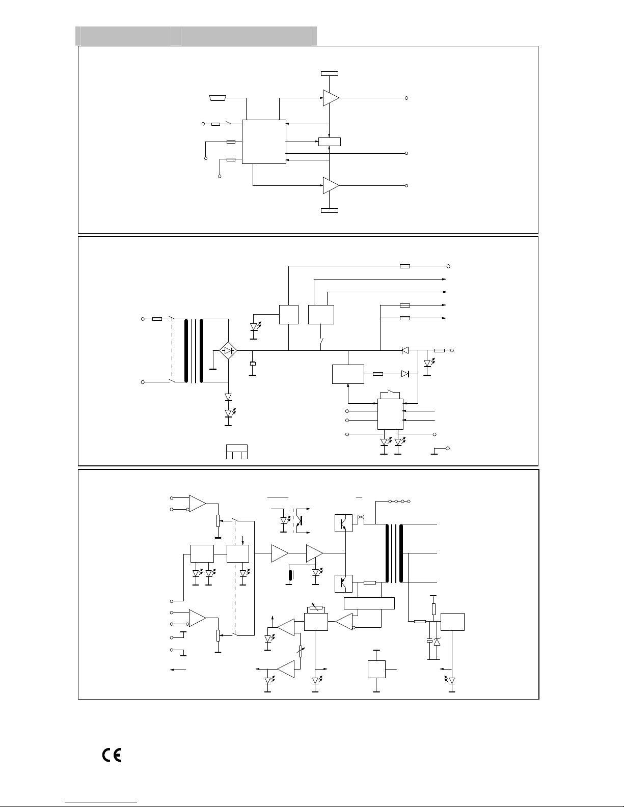
Block Diagrams Front panel indicators
DISPLAY
PSU/
CHARGER
P2.200LS OVERALL
BLOCK DIAGRAM
ISSUE 1.
AMP
MODULE A
AMP
MODULE B
AMP
MODULE A
AMP
MODULE B
230VAC
50/60Hz
~
AUX 27.6V
OUT
24V SEALED
LEAD-ACID BATTERY
FAULTS
SHOWS THE OVERALL CONFIGURATION OF PSU AND AMP MODULES PLUS DISPLAY
SIP
PORT
HOT SWAP PORT B
HOT SWAP PORT A
P2.200LS PSU MODULE BLOCK DIAGRAM
ISSUE 1.
5AMP
HBC
35A
BATTERY
20A
20A
27.6 V
REGULATOR
3A
AC IN
44000µF 3A
AMP
MODULE A
AMP
MODULE B
AMP
MODULE A
AMP
MODULE B
16 SECONDS ON
15 MINUTES OFF
SLEEP
ENABLE
AUX
ON
230VAC
50/60Hz
~
AUX 27.6V
OUT
MONITOR
GROUND
OKPSU
FAULT
DISABLE
DC IN
20A
3A
10A
10A
ALL FUSES AUTOMOTIVE BLADE
TYPE, EXCEPT MAINS INLET
FUSE
AMP A FAULT
AMP B FAULT
OK, SIP4PSU FAULT, SIP3
AMP B FAULT, SIP2
AMP A FAULT, SIP1
SLEEP
LINE
IN
(AUX)
0dB
LEVEL
P2.200LS AMPLIFIER MODULE BLOCK DIAGRAM.
TWO PER P2.200LS ISSUE 1
LINE
IN
(MAIN)
0dB
LEVEL
MONITOR
ANALOGUE
SWITCH
ANALOGUE
SWITCH
CONTROL
50 V
100V
0V
CONTACT
(PTT IN)
OPEN
CIRCUIT
FAULT
SHORT
CIRCUIT
FAULT
DETECT
FAULT
HSP2
LOAD
HIGH
FAULT
HSP1
LOAD
LOW
FAULT
HSP4
DETECT
Vp
FAULT
HSP3
WINDOW
THRESHOLD
TONE
FAIL
DETECTS CURRENT
THROUGH RESISTOR
EARTH
FAIL
PROTECT
SLEEP IN
-18 -6 -3 0
OUTPUT LEVEL
LOGIC
15V
REG
Vp out
+24 Vin
GROUND
+24V IN
OUTPUT
4TH ORDER BANDPASS
FILTER @ 22.05KHz
RLA1
RLA
1
OK HSP6
HSP5
IF LOAD LOW & TONE FAIL OR PROTECT THEN OK
HSP = HOT SWAP PORT.
CAN AVOID HOT SWAP IF NATURE OF
FAULT MEANS THERE IS NO POINT
AMP FAULT TO PSU
(OPEN CIRCUIT OR
SHORT CIRCUIT OR
LOAD HIGH OR LOAD
LOW OR TONE FAIL OR
EARTH FAULT)

Page 3 of 12 DocNo.DCP0001326 DSM 06/01/05 rev7
Each amplifier’s current status is displayed on the front panel, along with output bar graphs for each channel,
and the access status. All indicators are in accordance with BS 5839: Part 4: 1988.
Each amplifier module has a separate indication on the front panel for the following states:
Name Function / Description
1
Output level A four-element moving dot display shows the current amplifier output
level in logarithmic steps with 0dB being full power.
2
Priority The control contact on the main input is closed.
3
Protect The onboard protection systems have been activated and the load is
now isolated.
4
Sleep This facility is not used as it does not comply with BS5839-8
5
Load Hi The load monitoring system has detected an open circuit or higher
impedance than was set at commissioning.
6
Load Low The load monitoring system has detected a closed circuit or lower
impedance than was set at commissioning.
7
Contact Fault The main input control contact or wiring is either open circuit or short
circuit.
8
Tone fail
(Load Hi and Load Low lit)
The amplifier cannot detect the 22 kHz monitoring tone.
The power supply unit also has front panel status indication for the following states:
Name Function / Description
1
AC in The AC mains supply is healthy.
2
DC in The reserve battery supply is in use.
3
PSU Fault The battery charger has detected either a short circuit or high
impedance battery.
4
Aux. on The auxiliary power supply for external equipment is available.
5
OK All the functions of the amplifier are normal.
Page 4 of 12 DocNo.DCP0001326 DSM 06/01/05 rev7
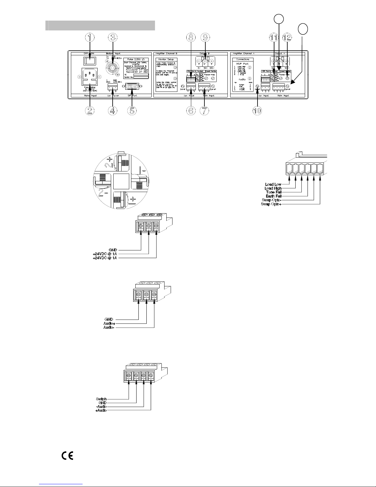
Name Function/Description
Name Function/Description
1
Switch Switches mains power
2
AC Input 6A IEC 3 pin connector
(Fuse: 5A 250V 20mm HBC)
3
Battery
Input
Rear of CliffCon 4
PC/P
Pin 1- : GND
Pin 1+ : +24V DC
@ 20A
8
Hot Swap
Port
4
Aux.
Power
9
Output See Output Connections
5
SIP Port See Internal Adjustments (page 9)
10
Level
control
Audio level control of
closest input.
6
Aux.
audio
input
11
LEDs
OC, The main input control wiring
is open circuit.
SC The main input control wiring is
short circuit.
E, Earth fault The 100V
loudspeaker line has a short to
ground.
Hi, Load High. Open circuit
detected, or a impedance higher
than commissioned.
TF, Tone Fail The monitor tone on
the input signal is not detected.
Lo, Load Low. Closed circuit
detected or lower impedance than
commissioned.
12
Window
13
Threshold
7
Main
audio
input
Switch: 470R to GND = on
6k8 to GND = off
See mix mute settings on page 9
14
Level
Used to set-up the fault
monitoring circuitry (see
page 6)
Rear panel controls & features
13 14
 Loading...