

Signet PDA200, PDA800 Operation & Instruction Manual
Page 1
Doc No. DCP0000487 JH 12/7/99 rev3
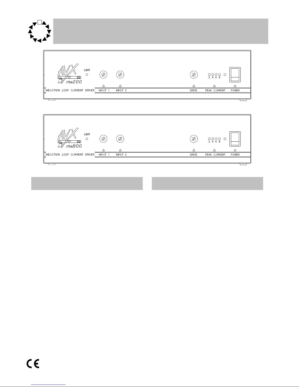
Features Technical Description
• PDA200 provides up to 120m
2
coverage
• PDA800 provides up to 400m
2
coverage
• Automatic tracking compressor
• Two selectable Mic/Line inputs
• Hidden controls
• X-talk connector
• Popular 5pin Din connectors
• Input peak LED
• Output current meter
• Free standing case
The PDA200 & PDA 800 are constant current induction loop amplifiers.
They use an advanced and unique
‘floating sense system’ to achieve greater
efficiency and to correct the phase problems created by driving an inductor.
The PDA 200 and 800 have a wide
range companding system to give a constant output level for a varying input
level. This is particularly useful when
dealing with fixed microphones used by
people moving within the space around
it; the compander compensates for these
changes in level.
A Compressor output is available to
connect a tape recorder to the loop amplifier so that a recording can be made
using the compander which is of a much
higher quality than the auto gain system
in many tape recorders.
Operation Instruction Manual
PDA200 & PDA800
Audio frequency induction
loop ampilifiers

Page 2
Doc No. DCP0000487 JH 12/7/99 rev3
AC power operation
For normal AC operation, plug the AC power
supply cord in a wall outlet of 230 V specified
voltage. The unit complies with BS415.
AC power cord
The wires in the mains lead supplied with the
unit are coloured in accordance with the following code.
Green and Yellow Earth
Blue Neutral
Brown Live
As the colours of the wires in the mains lead of
this unit may not correspond with the coloured
markings identifying the terminals in your plug,
please connect as follows.
Wire Plug terminal
Green & Yellow ‘E’ mark
‘EARTH’ symbol mark
‘GREEN’ mark
‘GREEN AND YELLOW’ mark
Blue ‘N’ mark
‘BLACK’ mark
‘BLUE’ mark
Brown ‘L’ mark
‘RED’ mark
‘BROWN’ mark
Caution
To prevent electric shock do not remove
the cover
Upon receipt of the amplifier shipment, please
inspect for any damage incurred in transit. If
damage is found, please notify your local representative and the transport company immediately. State date, nature of damage and whether
any damage was noticed on the shipping container prior to unpacking. Please give the waybill
number of the shipping order.
The unit should not be placed in areas;
1. with poor ventilation
2. exposed to direct sunlight
3. with high ambient temperature or adjacent to
heat generating equipment
4. with high humidity or dust levels
5. susceptible to vibration
Unpacking

Page 3
Doc No. DCP0000487 JH 12/7/99 rev3
Installation Input connections
Two input connectors are standard 5 pin
Din types. Both are mic or line selectable dependant upon the pin connections used, use the
following chart or see the back of the unit which
has the pin outs marked next to the relavent
connector.
Unbalanced Balanced
line line
pin4 signal pin4 Hot
pin5 link to pin2 pin5 Cold
pin2 ground pin2 ground
Unbalanced Balanced
microphone microphone
pin1 signal pin1 Hot
pin3 link to pin2 pin3 Cold
pin2 ground pin2 ground
Phantom is supplied on pins 1 and 3. 15V, 5mA
maximum per pin.
Alert input
For a simple alert signal, closing a switch
across pins 1 & 2 generates a 2KHz tone at 2Hz
on/off rate. The alert input can also be connected
to fire alarms/doorbells etc., however when connecting to a doorbell you must use a separate
isolated contact on the doorbell switch.
pin1 Trigger
pin2 Ground
pin3 5V
pin4 Tone in
pin5 Alert Tone.
Pins 4 & 5 must be linked at all times.
Read this manual throughally before starting installation, the following procedure should
be used.
1. Install the loop (see page 6)
2. Before connecting a loop to the amplifier use a
multimeter to check the loop is not shorted to
ground at any point, (it will almost certainly
damage the amplifier if it is).
3. Connect music or speech input signal to the
amplifier. The peak line level of this signal
should be approximately 1V.
4. Ensure input levels controls and drive control
are fully anti-clockwise. .
5. Increase the input level controls until the ‘limit’
LED is just flashing. This indicates that the
dynamic range processor is receiving a signal
of the correct level. The compression ratio is
fixed at a ratio of 20:1. If you are using both
inputs the level controls act as a simple mixer.
6. Adjust the drive control until the required cur-
rent peak is produced. (see page 5). Care
should be taken when doing this to ensure
the current is within the recommended
rating of the cable. The average current
output should be approximately one quarter of the maximum peak.
7. Using an induction loop receiver (eg SigNET
Rxti2), listen to the signal inside the loop. It is
also advisable to check the system with a field
strength meter. Please note that the orientation
of the field strength meter may influence the
reading.
Mains Hum
Background hum can sometimes be heard
when testing an installation especailly when testing with a induction loop reciever. This is not
caused by the loop system and will NOT normally be heard by hearing aid users, due to built
in filtering in most hearing aids.
The source of mains hum is most likely to
be ( 50 Hz) mains wiring, particularly in old
buildings where Live and Neutral cables may
take different routes, thus creating an induction
loop radiating at 50Hz.
If the client complains of mains hum simply
disconnect the loop to prove that the source is
unrelated.
 Loading...