

Page 1
Page 1
Doc No. DCP0000518 JH 12/7/99 rev2
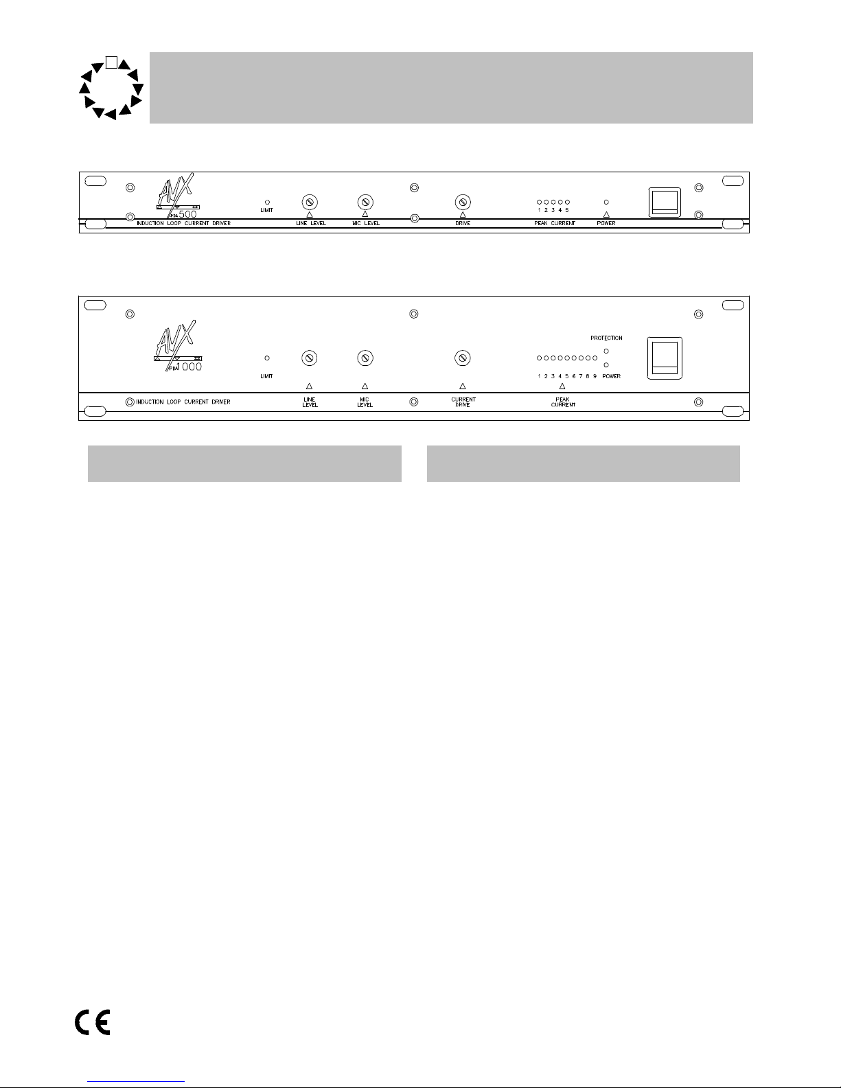
Features Technical Description
• PDA500 provides up to 250m
2
coverage
• PDA1000 provides up to 550m
2
coverage
• Automatic tracking compressor
• Line input
• Mic input
• Hidden controls
• Popular 3pin XLR connectors
• Input peak LED
• Output current meter
• 19” rack mounting case
Operation Instruction Manual
PDA500 & PDA1000
Audio frequency induction
loop ampilifiers
The PDA series are constant current audio
frequency induction loop amplifiers. They use an
advanced and unique floating sense system to
achieve greater efficiency and to correct the
phase problems created by driving an inductor,
whilst also providing exceptional sound quality
The pre amplification stage in the PDA
series incorporates an advanced signal processing system which allows tight control to be maintained over the signal. This is achieved with only
minimal degradation of the signal and is unnoticeable in normal operation. This is far more
advanced and sophisticated system than that
found in many dedicated signal processing units.
The processor can be switched between
compression and compansion (compression and
expansion). Expansion is limited to 28 dB to
prevent background noise and hiss being amplified. Compression up to 90dB is available. The
compression ratio is dynamically variable. For
most applications the processor should be set
for compression, however compansion should
be used in installations where there are a large
number of microphones and little or no external
signal processing.
Page 2

Page 2
Doc No. DCP0000518 JH 12/7/99 rev2
AC power operation
For normal AC operation, plug the AC power
supply cord in a wall outlet of 230 V specified
voltage. The unit complies with BS415.
AC power cord
The wires in the mains lead supplied with the
unit are coloured in accordance with the following code.
Green and Yellow Earth
Blue Neutral
Brown Live
As the colours of the wires in the mains lead of
this unit may not correspond with the coloured
markings identifying the terminals in your plug,
please connect as follows.
Wire Plug terminal
Green & Yellow ‘E’ mark
‘EARTH’ symbol mark
‘GREEN’ mark
‘GREEN AND YELLOW’ mark
Blue ‘N’ mark
‘BLACK’ mark
‘BLUE’ mark
Brown ‘L’ mark
‘RED’ mark
‘BROWN’ mark
Caution
To prevent electric shock do not remove
the cover
Upon receipt of the amplifier shipment, please
inspect for any damage incurred in transit. If
damage is found, please notify your local representative and the transport company immediately. State date, nature of damage and whether
any damage was noticed on the shipping container prior to unpacking. Please give the waybill
number of the shipping order.
The unit should not be placed in areas;
1. with poor ventilation
2. exposed to direct sunlight
3. with high ambient temperature or adjacent to
heat generating equipment
4. with high humidity or dust levels
5. susceptible to vibration
Unpacking
Page 3

Page 3
Doc No. DCP0000518 JH 12/7/99 rev2
Read this manual throughally before starting installation, the following procedure should
be used.
1. Install the loop (see page 6)
2. Before connecting a loop to the amplifier use a
multimeter to check the loop is not shorted to
ground at any point, (it will almost certainly
damage the amplifier if it is).
3. Connect music or speech input signal to the
amplifier. The peak line level of this signal
should be approximately 1V.
4. Ensure input levels controls and drive control
are fully anti-clockwise. .
5. Increase the input level controls until the ‘limit’
LED is just flashing. This indicates that the
dynamic range processor is receiving a signal
of the correct level. If you are using both inputs
the level controls act as a simple mixer.
6. Adjust the drive control until the required cur-
rent peak is produced. (see page 5). Care
should be taken when doing this to ensure
the current is within the recommended
rating of the cable. The average current
output should be approximately one quarter of the maximum peak.
7. Using an induction loop receiver (eg SigNET
Rxti2), listen to the signal inside the loop. It is
also advisable to check the system with a field
strength meter. Please note that the orientation
of the field strength meter may influence the
reading.
Mains Hum
Background hum can sometimes be heard
when testing an installation especailly when testing with a induction loop reciever. This is not
caused by the loop system and will NOT normally be heard by hearing aid users, due to built
in filtering in most hearing aids.
The source of the hum is most likely to be
mains wiring, particularly in old buildings where
Live and Neutral cables may take different
routes, thus creating an induction loop radiating
at 50Hz.
If the client complains of mains hum simply
disconnect the loop to prove that the source is
unrelated.
Installation Input connections
Two input connectors are standard 3pin
XLR. One input is for line level the other for mic.
level signals. For pin connections use the following chart or see the back of the unit which has
the pin outs marked next to the relavent connector.
LIne Input
Microphone input
Unbalanced Balanced
pin1 ground pin1 ground
pin2 signal pin2 Hot
pin3 link to pin1 pin3 Cold
Unbalanced Balanced
pin1 ground pin1 ground
pin2 signal pin2 Hot
pin3 link to pin1 pin3 Cold
Phantom is supplied on pins 2 and 3,
44V, 5mA maximum per pin.
Page 4

Page 4
Doc No. DCP0000518 JH 12/7/99 rev2
Output connections
Loop output
The output is via two 30A 4mm terminal
posts. Connection can be made by way of tails or
4mm plugs. Tails are recommended as they are
very unlikely to be pulled out.
WARNING: The PDA amplifiers are capable of producing short term peaks of twice their
rated current.
Internal adjustments
Duck
Off
(Default)
No attenuation
On For every 1 dB increase above
threshold, the microphone input is attenuated by 10 dB, to
a maximum of 60dB.
The duck feature when selected, attenuates
the microphone input signal when the line input
signal passes a pre-set threshold level. The duck
is used to eliminate any echo that may be occur
due to the signal from the stage/line input being
heard, then after a short delay, heard again from
the audience response microphone which picks
up the signal amplified by the main PA system.
This will only occur when a loop system incorporating an audience response microphone is used
in conjunction with a stage/ front of house signal
feed to the line input.
Compand/ compress
Compress
(Default)
pins 1&2
At a factory set level the compression ratio will be automatically changed to keep prevent
clipping. This option gives the
best sound quality and should be
selected if the input is from a
mixing desk or theatre stage for
example.
Compand
pins 2&3
This option can be used set for a
system which has a large number
of microphones or is likely to
suffer from poor mic use. The
tracking compressor will give
±15dB gain to the signal to try to
keep the level as level as possible.
These adjustments should only be carried
out by qualified personnel. The power lead
must be disconnected before the top cover
is removed.
Page 5

Page 5
Doc No. DCP0000518 JH 12/7/99 rev2
To calculate the required current it is first
necessary to calculate the aspect ratio of the
loop. This is the width of the loop divided by the
length of the loop, assuming the loop approximates to a rectangle. Circular loops should be
approximated to a square. If the room is L shaped, assume it is a square or rectangle and
use the longest side and the longest width. (For
this case, the calculated peak current required
will be too large, so reduce the drive level slightly)
It is also necessary to know the total length of the
loop cable. If the connecting cable from the
amplifier to the loop is the same cable as used
for the loop, then this should also be included.
The calculations below assume that the
loop will be approximately the same level as the
receiver. (Vertical displacement) If the loop is
significantly higher or lower (more than one to
two metres) than the receiver, then the peak
current required will be slightly higher.
Peak current calculation
Refer to the current width- graph to establish the required peak current. The width of the
loop is shown on the x-axis. The peak current is
shown vertically on the y-axis.
This is the peak current. The average
current output should be approximately one
quarter of the maximum peak.
Move along the x-axis until you come to the
width of your loop, then move up until you come
to one of the aspect ratio lines. From this point,
read the peak current required.
The D.C resistance of the loop should be
between 0.2 Ohms and 2 Ohms. It is very unlikely that any loop will be less than 0.2 Ohms as
this is virtually a short. It is quite acceptable to
have a D.C resistance greater than two Ohms,
but full current drive may not be possible.
Peak current calculation
Page 6

Page 6
Doc No. DCP0000518 JH 12/7/99 rev2
Loop cables
Cable selection
Almost any single core cable (multi-strand
or solid core) can be used for the loop provided it
is of the appropriate impedance. Ideally the DC
impedance of the loop should be 1 Ohm (<0.2
Ohm or >2 Ohm will result in a degradation in
signal). The following table gives some useful
approximations.
Use of a tri-rated cable is recommended.
This is cable with a tougher than usual jacket,
the reason being; damage will occur to the amplifier if at any point the loop is grounded.
Loop cable should ideally be laid at floor
level but in certain circumstances this may not
be possible. Any large amounts of metal (eg
steel meshed reinforced concrete floors) will absorb some of the signal strength, in this case the
cable may have to be mounted in the walls.
Aluminium (suspended ceilings) being
para-magnetic should also be avoided, mounting
a loop above a aluminium suspended ceiling will
probably result in almost no coverage, turning up
the output of an amplifier would just make matters worse as it will just stress the output stage
(and minutely warm the aluminium) resulting in a
definite shortening of the life-span of the amplifier.
Recommended cable gauge
PDA500 1.0 -2.5mm
2
PDA1000 2.5 - 5mm
2
Use of cables outside the recommended
gauges may may result in damage to the unit,
or risk of fire.
Optimum cable lengths:
Cable diameter Optimum lengths
1.0mm
2
30 - 70 metres
1.5mm
2
70 - 100 metres
2.5mm
2
100 - 165 metres
4.0mm
2
165+ metres
Only use cable diameters recommened for each
unit
Speaker positioning
If a speaker is placed near or beside a loop
cable the cross-over in the speaker may pick up
the loop signal, so try to keep speakers and loop
cables as far apart as possible. Normally this
does not show up in use because loop and
speaker have the same programme material,
only where the loop has a different signal to the
speakers (e.g. stage talk back systems)will this
become an issue.
Feeder Cables
When connecting an amplifier to a loop
some distance away use a heavy gauge twisted
pair (4-6mm2 ). This will have a negligible
impedance, as such the amplifier will not drive
against it and the power will be fed into the loop
where it can do useful work. For the cable size of
the actual loop, follow guidelines opposite.
Test loops
We always recommend the laying of a test
loop, there is no such thing as a standard installation and sometimes only a test loop will uncover
problematic areas.
Feedback
Long lengths of unbalanced signal cable
may cause feedback when placed inside the
loop. This problem can be virtually eliminated by
using balanced signals.
Problems may occur when using standard
dynamic microphones. The coil inside may act
as a receiver and cause feedback. It is advisable
to use condenser microphones. These may require phantom powering, available on both microphone inputs.
Other sources of feedback are coils in other
equipment that is linked to the induction loop
system, for example guitar pickups.
Loop cable class
A loop cable is classed as a 2A cable under
IEEE 16th Edition wiring regulations. As such it
must be sited a minimum of 600mm away from
telephone, mains and control cables.
Loop cables
Page 7

Page 7
Doc No. DCP0000518 JH 12/7/99 rev2
Loop patterns
A loop pattern laid on the floor is a low cost
method to reduce over-spill by providing more
even field strength compared to the usual single
turn of cable laid around the room’s perimeter.
The basic pattern looks like the diagram below:
Large areas and multiple rooms
Use several loop patterns, each pattern
must be connected to a separate loop amplifier.
When laying out patterns, ensure each is 90
degrees out of phase with its neighbours as per
the following diagrams which show a two story
building:
Note. For a two storey building the same loop
position on different floors is also 90 degrees out
of phase.
Non-rectangular rooms
Layout as per a basic pattern and step back the
prongs to the shape of the room.
Each pattern should be considered as a
many pronged fork. The pattern should be
spaced approx. 2m from nearest wall / next
pattern, prongs of the fork should be spaced
approx. 2m apart and should be approx. 2m
wide, prongs should extend to approx. 3/4m of
base of fork.
Assume the cable is being run around the
edge of a room for cable diameter calculations,
as the pattern restricts the amount of power
which can be fed into the loop. The large black
arrow shows clockwise direction of loop. Break
into pattern at any point to connect PDA unit.
Loop patterns
Page 8

Page 8
Doc No. DCP0000518 JH 12/7/99 rev2
SigNET Amplification & Control
Tower Road,
Glover Estate,
Washington,
Tyne & Wear, NE37 2SH
Tel: +44 (0) 191 417 4551
Fax: +44 (0) 191 417 0634
Inputs Two - XLR. Balanced - elec-
tronically
Microphone 200 Ohms - balanced
47 K Unbalanced
Sensitivity -66 dBm to -2dBm
Line Impedance10 K balanced;
20 K unbalanced
Sensitivity -20 dBm to + 22
dBm
Performance Bandwidth At any output level -
20 Hz to 16 KHz - 3 dB
Distortion < 0.05% THD @ 1
KHz
Dynamic range >90 dB
Noise <-86 dB
CMRR >84 dB
Input level
control
Line: -ì to +6 dB
Mic: -ì to + 66 dB
Mains voltage 230 V AC ± 20%
Power
Consumption
PDA500 < 100 VA
PDA1000 < 225 VA
Dimensions Width 482 mm
Height 44 mm PDA500
88 mm PDA1000
Length 243 mm.
Specification
PDA 1000 Output Drive current
Max peak > 16 A
EBU PPM > 12 A
Sine - 1KHz > 5 A RMS
Loop coverage > 540m
2
Loop impedance 0.2 to 2 ohms
PDA 500 Output Drive current
Max peak > 10 A
EBU PPM > 8 A
Sine - 1KHz > 2.6 A RMS
Loop coverage > 220m
2
Loop impedance 0.2 to 2 ohms
Specification
 Loading...