

Signet GF 5600 User Manual
‡ SIGNET 5600 Batch Controller
ENGLISH
*3-5600.090-1*
3-5600.090-1 (Rev. D-6/03) English
Contents
1. Wiring terminals
2. Power Connection
3. Compatible Sensor Wiring
4. Batch Contact Wiring
5. Remote Control Wiring
6. End of Batch/Counter Pulse Output Wiring
7. Option Contact Wiring Options
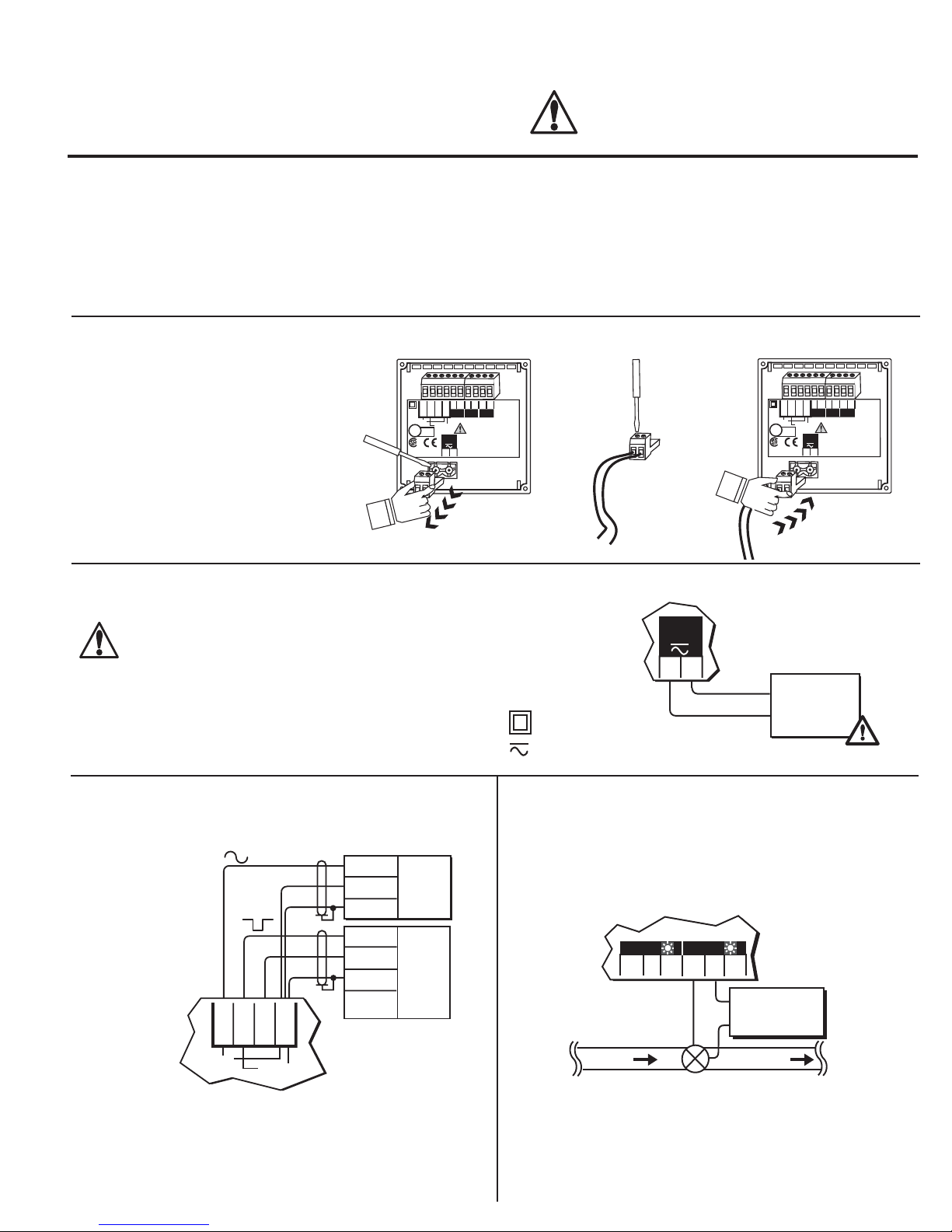
1. Wiring terminals
• Remove terminal blocks for easy wiring.
CAUTION!
• Remove power to unit before wiring input and
output connections.
• Follow instructions carefully to avoid personal
injury.
8. Current Output Wiring Options
9. 5600 Operation Modes
10. Menu Functions
11. Parts and Accessories
12. Specifications
13. Quick Reference Menu Parameters
14. Maintenance
15. Troubleshooting
1.
1 2 3 4 5 6
1 2 3 4
2
+
1
Gnd
+
Gnd
Total
AUX
Std. Sensor
U
PLS
Freq. IN
Freq. IN
Iso. Gnd
Sen. Pwr.
output
output
Open Collector
Sensor
LISTED
L
77CJ
12-24 V
10 W
+
-
1 2
Flow
reset
Patent No. D376,328
2.
1
2
3.
1 2 3 4 5 6
1 2 3 4
2
+
1
Gnd
+
Gnd
Total
AUX
Std. Sensor
U
PLS
Freq. IN
Freq. IN
Iso. Gnd
Sen. Pwr.
output
output
Open Collector
Sensor
LISTED
L
77CJ
12-24 V
10 W
+
-
1
2
Flow
reset
Patent No. D376,328
2. Power Connection
CAUTION!
Never connect 115 VAC or 230 VAC to rear power
terminals. High voltage AC will damage instrument and
void warranty.
Technical Notes:
• Maximum 4-20 mA loop impedance (sec. 8A) is affected by the
supply voltage.
• To reduce the possibility of noise interference, isolate AC
power lines from signal lines.
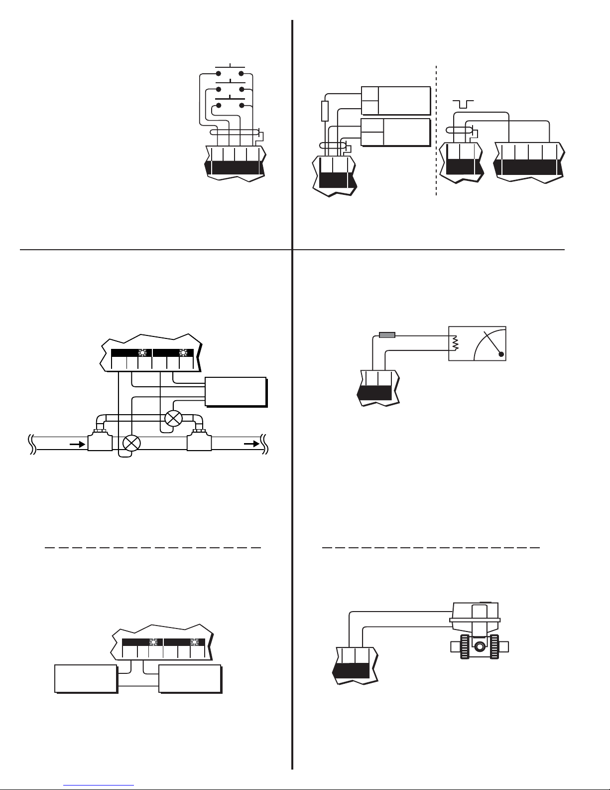
3. Compatible Sensor Wiring
+GF+
SIGNET Sensors:
Std. Sensor
Freq. IN
Freq. IN
Iso. Gnd
Sen. Pwr.
Open Collector
Sensor
Red
Black
Shld.
Red
Black
Shld.
5600
Terminals
515
525
2517
2000
2507
2536
2540
2550
Vortex*
5600
12-24 V
10 W
Terminals
External power
+
-
supply
-
12 - 24 VDC
OR
= Double Insulated
12 - 24 VAC
+
= DC or AC power
4. Batch Contact Wiring
See section 9 for simple and advanced mode configuration
options.
5600
Option
NO
Batch
C
NC
NO
C
Terminals
NC
AC or DC
power
flow
valve
Technical Notes:
• To reduce the possibility of noise interference, route sensor
cable )away from AC power lines.
• *Vortex sensor or system frequency output
ÐSIGNET 5600 Batch Controller
Technical Notes:
• Maximum alarm contact ratings: 5 A @ 30 VDC, 5 A @ 125
VAC, or 3 A @ 250 VAC
• To reduce the possibility of noise interference, isolate AC power
lines from signal lines.
1 of 12
5. Remo)te Control Wiring
Rear START, STOP, and RESUME
(Rsm) terminals can provide remote
batch control from a distance using
one of four methods:
• Mechanical switch closures (shown)
• End of batch pulse from a second
5600 (sec. 6)
• End of batch contact closure from a
second 5600 (sec. 7C).
• End of batch current pulse from a
second 5600 (sec. 8C).
Momentary Switch Contacts
(customer supplied)
5600
Terminals
Start
Stop
Remote
Rsm
Start
Stop
Resume
RTN
6. End of Batch/Counter Pulse Output Wiring
See section 9 for simple and advanced mode configuration
options.
A. External counter connection
+
5 - 30
VDC
Gnd
-
IN
Gnd
5600
External
Counter
10 kΩ
+
CNT/EOB
output
Terminals
B. Daisy chaining two 5600
batch controllers together
+
Gnd
CNT/EOB
output
First 5600
Start
Remote
Second 5600
Stop
Rsm
RTN
Technical Notes:
• Use 4-conductor shielded cable for remote control lines up to
30 m (100 ft) max.
7. Option Contact Wiring Options
A. Two Stage Shutdown (advanced mode only, sec. 9.2)
5600
Terminals
NC
AC or DC
power
to tank
NC
Valve
NO
Batch
C
Main line
flow
Bypass line
Option
NO
C
Technical Notes:
• Maximum alarm contact ratings: 5 A @ 30 VDC, 5 A @ 125
VAC, or 3 A @ 250 VAC
• To reduce the possibility of noise interference, isolate AC power
lines from signal lines.
Technical Notes:
• Use 2-conductor shielded twisted-pair cable for output lines
up to 30 m (100 ft.) max.
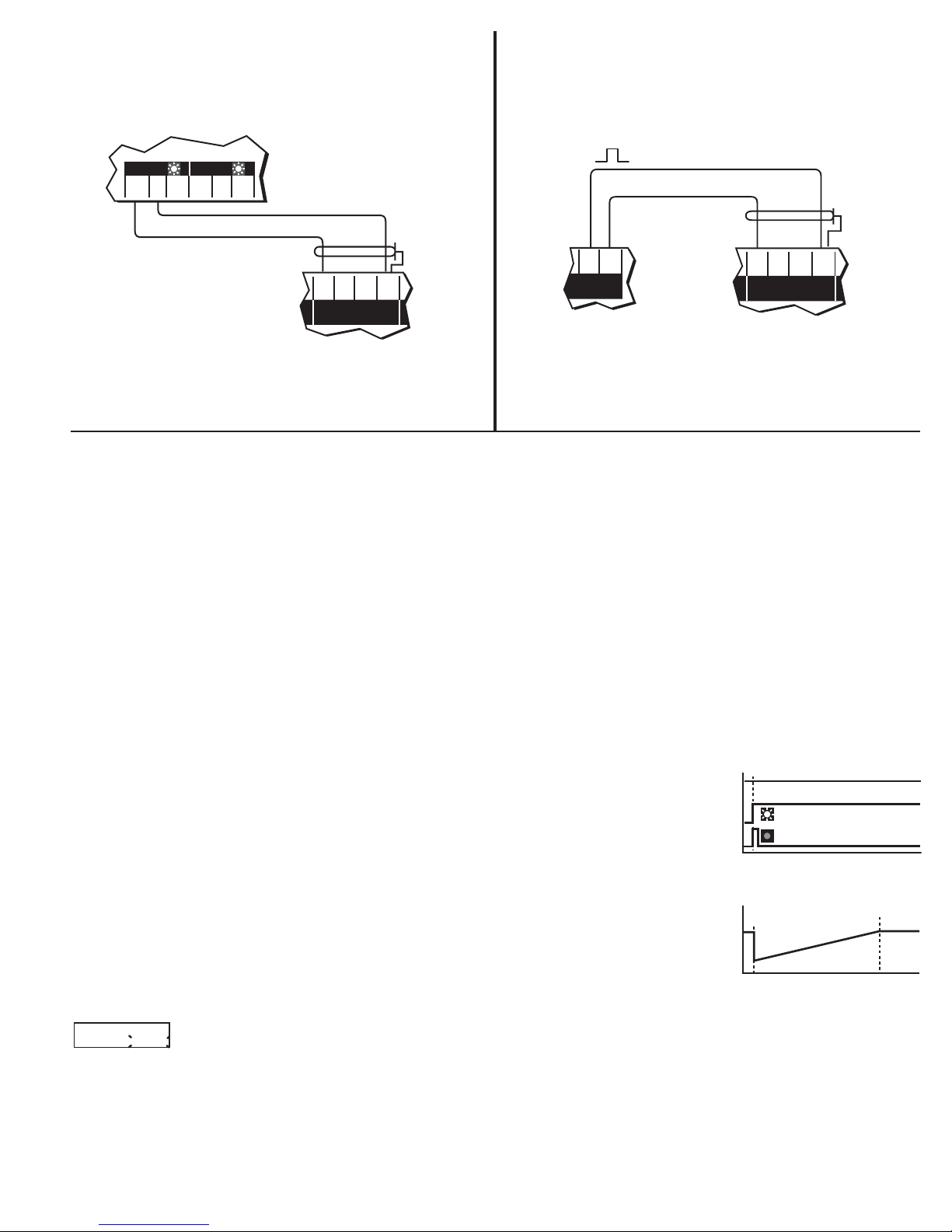
8. Current Output Wiring Options
A. Batch Completion (simple or advanced mode, sec. 9)
Fuse**
1/8A
+
4 - 20 mA
*
-
+
Current
output
Technical Notes:
**1/8A fuse recommended (customer supplied)
* 4-20 mA output is internally powered (non-isolated),
maximum loop impedance 350 ý with a 12 V instrument supply
voltage, 950 ý with a 24 V instrument supply voltage.
To isolate output and prevent ground loop problems:
1. Use monitor device with isolated inputs, or
2. Use separate DC supply for 5600 and monitor device, or
3. Power 5600 with 12 - 24 VAC step down transformer
-
5600
Terminals
B. Missing Signal Alarm (simple or advanced mode, sec. 9)
OR Overrun Alarm (advanced mode only, sec. 9.2)
5600
Terminals
Alarm
device
Option
NO
C
NC
Batch
NO
AC or DC
C
power
NC
Technical Notes:
• Maximum alarm contact ratings: 5 A @ 30 VDC, 5 A @ 125
VAC, or 3 A @ 250 VAC
• To reduce the possibility of noise interference, isolate AC power
lines from signal lines.
2 of 12
B. Valve Control (advanced mode only, sec. 9.2)
#5 ( + )
4 - 20 mA
#6 ( - )
-
5600
Terminals
George Fischer electronic
actuator with PE 22P
positioner required
+
Current
output
Technical Notes:
• Output compatible with the following George Fischer electronic
actuators/PE 22P positioner models: EA 20, EA 30, EA 41
and EA 50
ÐSIGNET 5600 Batch Controller
Section 7 Continued...
Section 8 Continued...
C. End of Batch Pulse (advanced mode only, sec. 9.2)
Daisy chaining two 5600 batch controllers together for a second
batching stage.
C. End of Batch Pulse (advanced mode only, sec. 9.2)
Daisy chaining two 5600 batch controllers together for a second
batching stage.
5600
NC
NO
Batch
C
Option
NO
C
First 5600
Technical Notes:
• Use 2-conductor shielded twisted-pair cable for contact lines
up to 30 m (100 ft.) max.
NC
Second
5600
Terminals
Start
Remote
Stop
Rsm
RTN
-
5600
Terminals
Rsm
Stop
Start
Remote
Second 5600
RTN
+
Current
output
First 5600
Technical Notes:
• Wiring MUST be connected exactly as shown.
• Use 2-conductor shielded twisted-pair cable for output lines
up to 30 m (100 ft) max.
9. 5600 Operation Modes
This section gives a detailed description of the 5600's simple and advanced operation modes (sec. 14) and how they affect the batch
contact, End of batch/totalizer output, option contact, and current output.
9.1 Simple Operation Mode
• Batch Contact (sec. 4): In simple mode, the batch contact is dedicated for on/off control. It is energized at the start of a batch and
de-energized at the end of a batch. It also de-energizes when STOP is selected from the front keypad or initiated by a remote contact
closure to the rear STOP terminals (sec. 5). A RESUME command can also be initiated by either method to complete the batch. The
front panel batch indicator turns on when the batch contact is energized.
• Counter/End of Batch Pulse Output (sec. 6): In simple mode, the output is configured as a counter pulse output. The output
emits a
130 millisecond pulse for each engineering (total) unit measured. The output is a open collector type which requires an external pull up
resistor and power supply for external counter use (sec. 6).
• Option Contact - Missing Signal Alarm (sec. 7B): This function provides alarm capability if flow is not
detected in 30 seconds after a batch cycle starts. If the flow sensor signal is missing, the option contact
energizes and the front panel contact indicator turns on, signaling the missing sensor signal. The batch
contact also
de-energizes, closing the flow control valve and stopping the batch. The alarm condition will remain until
the front panel ENTER key is pressed or a remote contact closure is made to the rear STOP terminal (sec.
5).
• Current Output - Batch Completion (sec. 8A): This function is offered in the simple or advanced
operation mode. The output is a linear increase from 4 mA at batch start to 20 mA at batch end.
Batch started...
Sensor input
option contact
batch contact
Batch running...
0%
4 mA
100%
20 mA
9.2 Advanced Operation Mode
Overrun Comp:
automatic manual
early, compensating for valve closing time and eliminating batch overrun. Automatic overrun compensation counts sensor pulses
during the batch cycle, and any excess pulses after the batch stops. The instrument calculates the estimated batch overrun based on
the additional sensor pulses, then automatically reduces the next batch size for the next batch. During the next batch cycle, the batch
contact de-energizes early, thus closing the flow control valve early and eliminating batch overrun.
ÐSIGNET 5600 Batch Controller
• Batch Contact (sec. 4): The batch contact is dedicated for on/off control and is either manually or automatically
compensated for batch overrun. Manual overrun compensation allows the operator to compensate for valve closure
time in a batching system. The operator is prompted to enter a batch volume that de-energizes the batch contact
3 of 12

Option Contact:
batch contact
Option contact
0%
100%
90%
Batch running...
Two Stage
• Counter/End of Batch Pulse Output (sec. 6): In advanced mode, the output can be
configured as either a counter pulse output (sec. 9.1) or as an end of batch pulse
output. When configured as an end of batch pulse, the output emits a 500 millisecond pulse at the
completion of every batch. The output is a open collector type which requires an external pull up resistor
and power supply for external counter use (sec. 6).
• Option Contact - Two Stage Shutdown (sec. 7A): This function is designed to prevent over filling or to minimize water hammer.
Both the batch and the option contact are energized when the batch starts. The option contact then de-energizes at a programmed batch percent-
Option Contact:
Overrun Alarm
energizes, completing the sequence. Front keypad and remote START, STOP, and RESUME
inputs (sec. 5) also control the option contact. The front panel contact indicator turns on when
the option contact is energized.
age, forcing flow through a smaller bypass line to reduce the fill rate. After the entire batch is measured, the batch contact de-
Batch running...
0%
Option contact
batch contact
100%
Overrun
• Option Contact - Overrun Alarm (sec. 7B): This function provides overrun alarm
capability for detecting a leaky or stuck valve. If the programmed batch overrun volume is measured after the batch
ends, the option contact is energized and the front panel contact indicator turns on, alarming
Option Contact:
End of Batch
the operator that the flow shut off valve is leaking or stuck open. To cancel alarm, press the
ENTER key (or remote STOP switch) once. The overrun alarm will retrigger if the condition
persists.
Batch running...
0%
Option contact
batch contact
100%
500ms
• Option Contact - End of Batch Pulse (sec. 7C): This function is designed to trigger an external batch counter or second 5600 Batch Controller at
the end of a batch. The option contact is energized for 500 milliseconds at the end of every batch cycle. An external power
Option Contact:
Missing Signal
supply switched through the option contact's common (COM) and normally open (NO) terminal provides a pulse for triggering
these devices.
Option Contact:
Off
Missing Signal
Alarm: On
start-up. An adjustable time delay entry (in seconds) is offered which specifies how long the instrument will wait after batch
start-up before initiating the missing signal alarm. See simple operation mode (sec. 9.1) for alarm operation details.
• Option Contact On/Off (sec. 10.4H): This function enables or disables the option contact and front panel option LED.
When the option contact is configured "Off", the option contact and front panel LED are disabled.
• Missing Signal Alarm On/Off (sec. 10.4H):
Missing signal alarm is always enabled (factory default sec. 9.1) even if the option contact is selected to be a different function.
• Option Contact - Missing Signal Alarm (sec. 7B): The missing signal alarm represents a missing sensor signal after batch
Current Output:
Batch Completion
Current Output:
Valve Control
This function is designed to completely disable the missing signal alarm, if desired. NOTE: If disabled, the batch contact is
NOT affected and will NOT signal the operator or stop the running batch if there is a problem.
• Current Output - Batch Completion (sec. 8A): In advanced mode, the current output
functions identical to the simple operation mode. See the simple operation mode explanation
above.
Batch running...
0%
valve
20 mA
4 mA
100%
valve
• Current Output - Valve Control (sec. 8B): This function is designed for use with a George Fischer electric
actuator with PE 22P positioner for preventing overflow or minimizing water hammer. When a batch starts, the
current output is held at 20 mA, forcing the PE 22P positioner to the full open valve position. Near batch end, the output gradually ramps downward
to slow the flowrate, then drops to 4 mA closing the valve and ending the batch. Front keypad and remote START, STOP, and
Current Output:
End of Batch
RESUME inputs also control the output (sec. 5). A STOP command any time during a batch
sequence will force the output to 4 mA and close the PE 22P positioner. (Note: for optimum
performance, the batch process should last at least 1 minute!)
Batch running...
0%
0 mA
100%
20 mA
500ms
• Current Output - End of Batch (sec. 8C): This function is designed to trigger a second 5600 batch controller's
remote START input for a second batching stage. When the batch starts, the current output remains at 0 mA until the end of the batch, then jumps to
20 mA for 500 milliseconds. The 500 millisecond current pulse triggers the second 5600's remote START terminal to start the second batch stage.
4 of 12
ÐSIGNET 5600 Batch Controller
 Loading...