

Signet FMIC User Manual
Integrity Voice Alarm Routing Matrix
FMIC Manual
Page 1 of 8 DocNo.DCP0002986 ADS 11/12/05 rev0
IMPORTANT
THIS SECTION MUST BE READ PRIOR TO THE INSTALLATION / MAINTENANCE OF THIS PRODUCT
This equipment must only be installed and maintained by a suitably skilled and technically competent
person.
No responsibility can be accepted by the manufacturer or distributors of this product for any
misinterpretation of an instruction or guidance note or for the compliance of the system as a whole.
Voice alarm system design is beyond the scope of this document. An understanding of system
components and their use is assumed.
Errors and omissions excepted. The manufacturer’s policy is one of continuous improvement and we
reserve the right to alter product specifications at our discretion and without prior notice.
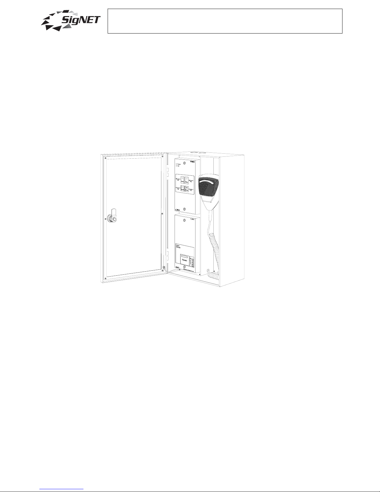
FMIC Overview
The FMIC comprises a wall-mounted red steel case with a glazed door that contains a close-talking
noise-cancelling fist microphone plus ancillary electronics.
It is designed to be used with SigNET’s Integrity voice alarm system and is fully monitored for faults. The
internal electronics comprise two parts, a 1ZPR pre-amplifier and monitoring unit and an FMX fault
monitoring expansion and message control unit.
Up to four FMICs may be connected in a daisy-chain format to one voice alarm input.
When used with the Integrity VA system, it is connected to a one 1LS card and, in most applications, is
required to operate as an all-call microphone, even in case of microprocessor failure. In this case, the
1LS card must be installed in slot 1 of the Integrity mainframe.
The microphone is designed for use in noisy environments and incorporates a lip-guide to help the user
position the microphone close, but not too close, to his mouth.
The FMIC is normally connected to the mainframe via two four-core 1.5mm
2
`fire-rated cables although in
non-life-safety applications, Cat 5 cable may be used.
The front door is normally secured by a cam lock and key, but a ‘T-bar’ handle may be specified if
required.

Integrity Voice Alarm Routing Matrix
FMIC Manual
Page 2 of 8 DocNo.DCP0002986 ADS 11/12/05 rev0
1ZPR Overview
The 1ZPR has an OK indicator to show that power is connected and there are no local faults. If a fault is
detected with the microphone or 1ZPR the OK light goes out and the FAULT light illuminates.
It also has a speak button which incorporates a Busy indicator/VU level meter.
The audio section features a compressor to cope with varying speech levels, a noise-gate to reduce
background noise, three-band equalization and a selectable chime module (0, 1, 2 or 3 chimes).
In order to page, the microphone’s PTT thumb switch or the 1ZPR’s speak button is pressed and,
provided the system is not busy at a higher priority (shown by the Speak bar flashing solid green), the
speak bar will light solid green and the announcement can be made. The VU meter follows the chime
sound and the operator should not speak until it has finished.
If the system is busy at an equal or higher priority pressing the PTT will have no effect.
FMX Overview
The FMX has a Power indicator that is lit when power is connected and a Fail indicator that lights if the
FMX or 1ZPR detects a fault.
The FMX’s controls and indicators work as follows when connected to a correctly configured Integrity VA
system:
Press the Message 1 “PLAY” button and the associated LED lights briefly. The message (normally
“Evacuate”) plays once and will stop when it reaches the end.
The message 2 controls and indicators are the same except that a “Test” message is normally
controlled.
Technical description
Speech is picked up by the microphone and the signals are passed to a voltage controlled amplifier
under control of a signal derived from rectifying the stage output signals, providing a 3:1 compression
ratio.
The output of this stage is fed to an LED output level display and a three-band equalizer (100 Hz, 1 kHz
and 10 kHz).
The audio line is monitored for faults by means of a 15 V phantom voltage that is injected from the 1LS
card.
Fault Monitoring
The electret microphone capsule is monitored for impedance and current absorption. Any deviation
outside a pre-set window is detected as a fault which turns off the OK LED and lights the Fault LED. At
the same time, the monitor circuit disconnects a 6k8 end of line resistor in the PTT circuit, causing the
PTT line voltage to rise. This is detected as a fault by the 1LS card.
Cables
The FMIC is designed to use two four-core fire-rated cables that enter the case via two 20 mm knockouts in the top or bottom of the case. In non life-safety applications, Cat 5 cable can be used instead. Up
to four FMICs can be daisy-chained on up to 1000 metres if cable (fire rated or Cat 5).
Integrity Voice Alarm Routing Matrix
FMIC Manual
Page 3 of 8 DocNo.DCP0002986 ADS 11/12/05 rev0
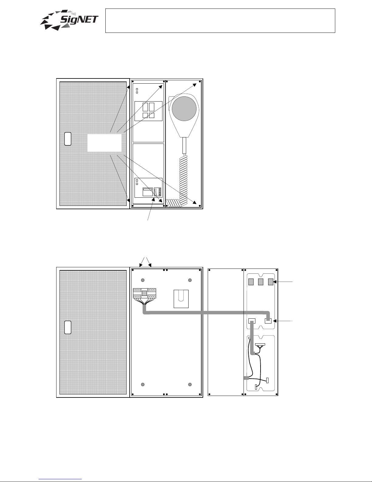
Installation
Open the door and remove the eight screws holding the back plate. If only two screws are fitted, the
other screws will be provided in a plastic bag.
Unplug the Cat 5 lead from the terminal block, remove the back plate and keep it safe.
The FMIC should be located in an area that will be as quiet as possible in an emergency.
Fix the box to the wall, normally between 1.2 and 1.4 metres from the final floor position using suitable
fasteners.
In the UK, standard or enhanced fire-rated cables (BS 5839-1 2002) should be used.
FMX
1ZPR
Eight back
plate screws
VU meter
unplug
Terminal block
DIP
Mounting holes
20 mm knockouts
Mic holder
 Loading...