


ENGLISH ESPAÑOL
MFL68920519_04
%Do not store or use gasoline or other flammable vapors and liquids in the
vicinity of this or any other appliance.
%WHAT TO DO IF YOU SMELL GAS
- Do not try to light any appliance.
- Do not touch any electrical switch.
- Do not use any phone in your building.
- Immediately call your gas supplier from a neighbor's phone. Follow the
gas supplier's instructions.
- If you cannot reach your gas supplier, call the fire department.
%Installation and service must be performed by a qualified installer, service
agency, or the gas supplier.
If the information in this manual is not followed exactly, a fire or explosion
may result causing property damage, personal injury or death.
WARNING
SKSDR360GS
OWNER’S MANUAL
DUAL FUEL RANGE
Read this owner’s manual thoroughly before operating the appliance
and keep it handy for reference at all times.
www.thesignaturekitchen.com
Copyright © 2017 Signature Kitchen Suite. All Rights Reserved.

2
TABLE OF CONTENTS
TABLE OF CONTENTS
4
IMPORTANT SAFETY
INSTRUCTIONS
13
PRODUCT OVERVIEW
13 Parts
13 Accessories
14
INSTALLATION
14 Installation Overview
14 Product Specifications
15 Before Installing the Range
17 Ventilation Requirement
17 Proper Location
20 Gas Supply
20 Electrical Supply
20 Installing the Range
24 Connecting the Range to Gas
25 Connecting Electricity
28 Engaging the Anti-tip Device
29 Test Run
29 Checking Ignition of the Surface Burners
31
OPERATION
31 Control Panel Overview
32 Getting Started
32 Changing Oven Settings
32 Settings
32 Lockout
33 Date & Time
33 Clock Themes
33 Sabbath Mode
34 Wi-Fi
34 Remote Start
34 Brightness
34 Display
34 Convection Auto Conversion
35 Language Selection
35 Volume
35 Preheat Alarm Light
35 Thermostat Adjustment
35 Temperature Units
36 Smart Diagnosis™
36 Program Update
36 Factory Data Reset
36 Open Source License
37 Using the Cooktop
37 Gas Cooktop Module
37 Cooktop Timers
38 The Gas Surface Burners
38 Before Use
38 Using the Gas Surface Burners
39 Setting the Flame Size
39 In Case of Power Failure
39 Cookware for Gas Burners
40 Extra Low Simmer (Small Burners Only)
40 Using a Wok
40 Using Stove-Top Grills
41 The Gas Built-in Griddle (available on some
models)
43 Using the Oven
43 Before Using the Oven
43 Oven Vent
43 Using Oven Racks
44 Accessories
44 Oven Cooling
45 Timer
45 Bake
46 Convection Modes
47 Rapidheat Roast
48 Recommended Baking and Roasting Guide
49 Broil
50 Recommended Broiling Guide
51 Warm
52 Proof
52 Probe
54 My Recipe
54 Gourmet Cook
55 Gourmet Cook Guide
56 Gourmet Steam Guide
57 Steam Function
58 Remote Start
59
SMART FUNCTIONS
59 SIGNATURE KITCHEN SUITE Application
60 Smart Diagnosis™ Function
61 Open Source Software Notice Information
62 FCC Notice
62 FCC RF Radiation Exposure Statement

3
TABLE OF CONTENTS
ENGLISH
63
MAINTENANCE
63 Control Panel
63 Gas Surface Burners
64 Burner Grates
64 Gas Cooktop Surface
65 Griddle
66 Exterior
67 Front Manifold Panel and Knobs
68 SpeedClean™
70 Self Clean
72 Oven Air Vents
72 Steam Feeder Tank
73 Cleaning Scale on Oven Bottom
73 Descaling
73 Drying
73 Evaporation
74 Removing and Replacing the Lift-Off Oven
Doors
75
TROUBLESHOOTING
75 FAQs
77 Before Calling for Service
81
WARRANTY
4
IMPORTANT SAFETY INSTRUCTIONS
IMPORTANT SAFETY INSTRUCTIONS
Read and follow all instructions when using the range to prevent the risk of fire, electric
shock, personal injury, or damage. This guide does not cover all possible conditions that
may occur. Always contact your service agent or manufacturer about problems that you do
not understand.
Download this owner's manual at: www.thesignaturekitchen.com
This is the safety alert symbol. This symbol alerts you to potential hazards that
can result in property damage and/or serious bodily harm or death.
All safety messages will follow the safety alert symbol and either the word
WARNING or CAUTION. These words mean:
WARNING
- Indicates a hazardous situation which, if not avoided, could result
in death or serious injury.
CAUTION
-
Indicates a hazardous situation which, if not avoided, could result
in minor or moderate injury.
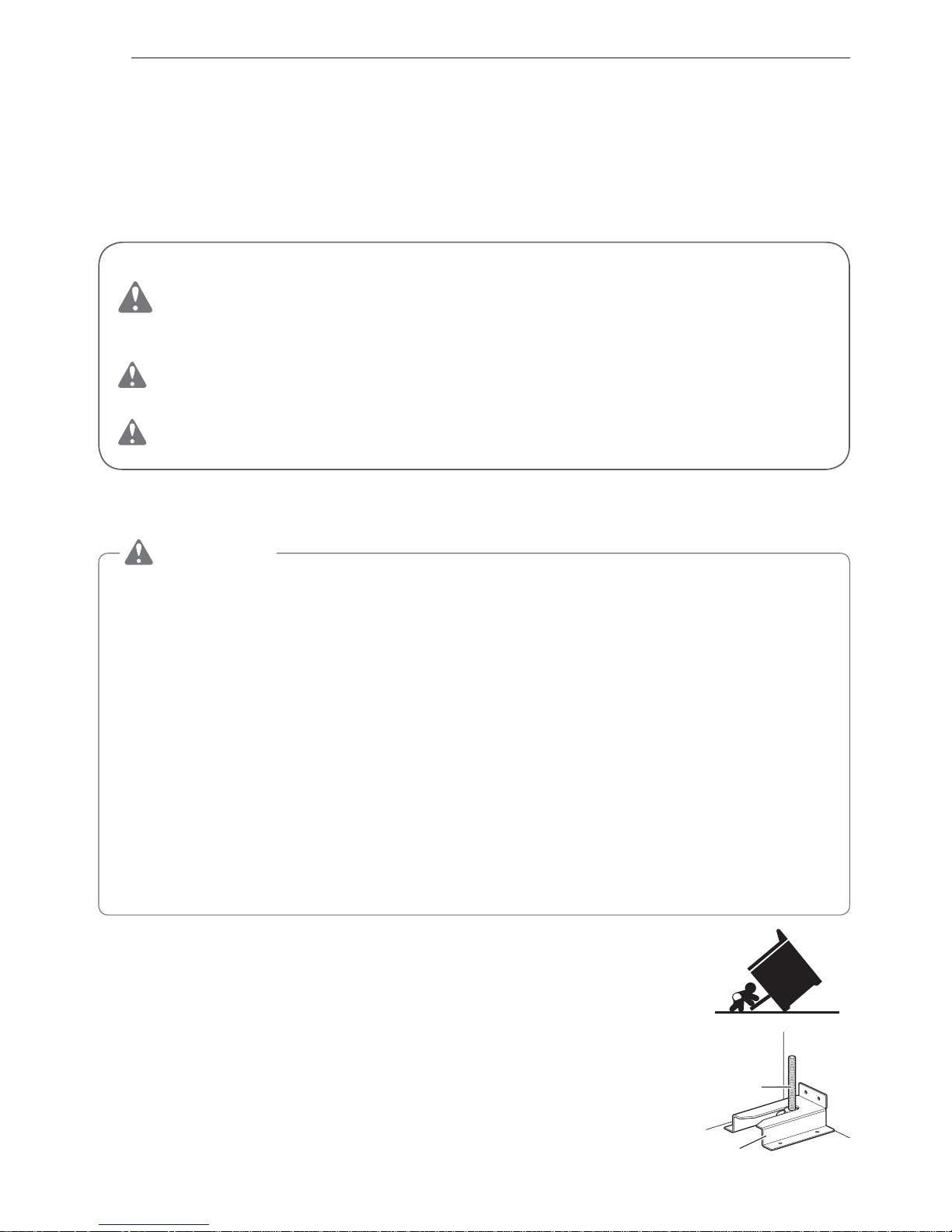
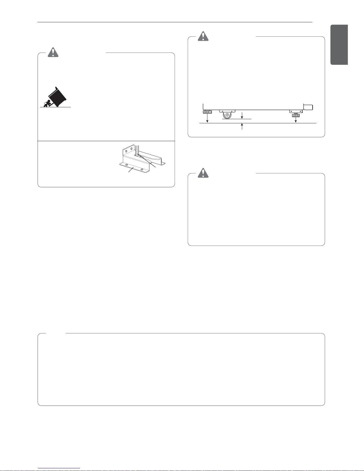
ANTI-TIP DEVICE
WARNING
%TO REDUCE THE RISK OF TIPPING, THE APPLIANCE MUST BE SECURED
BY A PROPERLY INSTALLED ANTI-TIP DEVICE. TO CHECK IF THE DEVICE IS
INSTALLED PROPERLY, VERIFY THAT THE ANTI-TIP DEVICE IS ENGAGED, OR
GRASP THE TOP REAR EDGE OF THE RANGE BACK GUARD AND CAREFULLY
ATTEMPT TO TILT IT FORWARD. Refer to the installation section for instructions.
%A child or adult can tip the range and be killed.
%Install the anti-tip device to the structure and/or the range. Verify the anti-tip device has
been properly installed and engaged following the instructions on the anti-tip bracket
template.
%Engage the range to the anti-tip device following the instructions on the anti-tip bracket
template. Ensure the anti-tip device is re-engaged when the range is moved by following
the instruction on the anti-tip bracket template.
%Re-engage the anti-tip device if the range is moved. Do not operate the range without
the anti-tip device in place and engaged.
%See installation instructions for details.
%Failure to do so can result in death or serious burns to children or adults.
%Never remove the oven legs. The range will not be secured to the
anti-tip bracket if the legs are removed.
%Do not step or sit on the oven door. The range could be tipped and
injury might result from spilled hot liquid, food, or the range itself.
%Do not rest large, heavy items such as whole turkeys on the open
oven door. The range could tip forward and cause injury.
%Reengage the anti-tip device after pulling the range out for
cleaning, service, or any other reason.
%Failure to follow these instructions can result in death or serious
burns to children or adults.
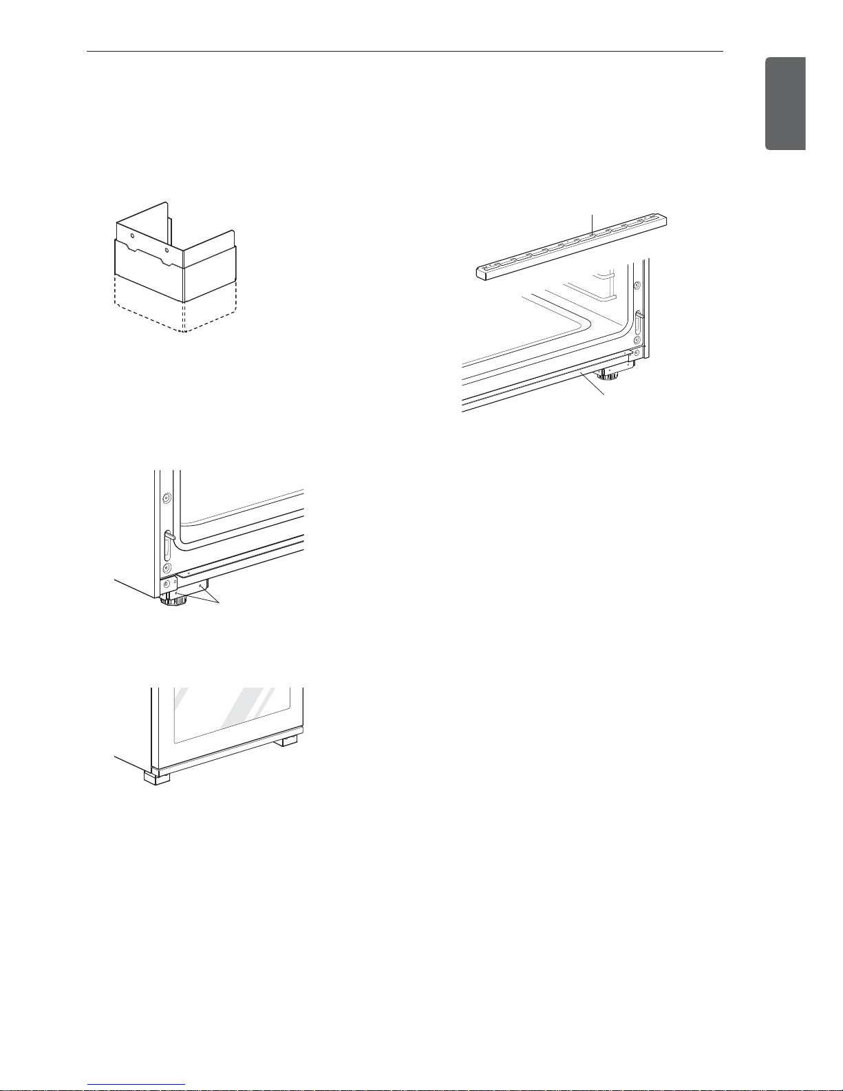
Anti-tip bracket
Leveling
leg
5
IMPORTANT SAFETY INSTRUCTIONS
ENGLISH
INSTALLATION SAFETY PRECAUTIONS
Have the installer show you the location of the range gas shut-off valve and how to shut it
off if necessary.
WARNING
%Make sure the range is properly installed and grounded by a qualified installer,
according to the installation instructions. Any adjustment and service should be
performed only by qualified gas range installers or service technicians.
%Make sure the range is properly adjusted by a qualified service technician or installer
for the type of gas (natural or LP) that is to be used. The range can be converted for
use with either type of gas. See the installation instructions.
%These adjustments must be done by a qualified service technician according to the
manufacturer’s instructions and all codes and requirements of the authority having
jurisdiction. Failure to follow these instructions could result in serious injury or property
damage. The qualified agency performing these adjustments assumes responsibility for
the conversion.
%Disconnect the electrical supply before servicing the appliance.
%Never use the appliance door as a step stool or seat, as this may result in tipping of the
appliance and serious injuries.
%This product should not be installed below ventilation type hood systems that direct air
in a downward direction.
Doing so may cause ignition and combustion problems with the cooktop resulting in
personal injury and may affect the cooking performance of the unit.
%To prevent fire hazard or electrical shock, do not use an adapter plug or an extension
cord, or remove the grounding prong from the electrical power cord. Failure to follow
this warning can cause serious injury, fire or death.
%To prevent poor air circulation, place the range out of the kitchen traffic path and out of
drafty locations.
%Do not attempt to repair or replace any part of the range unless it is specifically
mentioned in this manual. All other services should be referred to a qualified technician.
%Make sure that all packaging materials are removed from the range before operating it
to prevent fire or smoke damage should the packaging material ignite.
%After using the range for an extended period of time high floor temperatures may result.
Many floor coverings will not withstand this kind of use.
%Never install the range over vinyl tile or linoleum that cannot withstand such type of
use. Never install it directly over interior kitchen carpeting.
A
NSI/CSA Standard
Designation
MH62439
GAS-FIRED
6
IMPORTANT SAFETY INSTRUCTIONS
SAFETY PRECAUTIONS
The Safe Drinking Water and Toxic Enforcement Act requires the Governor of California to
publish a list of substances known to the state to cause birth defects or other reproductive
harm, and requires businesses to warn customers of potential exposure to such substances.
Gas appliances can cause minor exposure to four of these substances, namely benzene,
carbon monoxide, formaldehyde and soot, caused primarily by the imperfect combustion
of natural or LP gas. Correctly adjusted burners, indicated by a bluish rather than a yellow
flame, will minimize imperfect combustion. Exposure to these substances can be minimized
by opening windows or using a ventilation fan or hood.
WARNING
This product contains chemicals known to the State of California to cause cancer and
birth defects or other reproductive harm. Wash hands after handling. (US only)
%DO NOT TOUCH HEATING ELEMENTS OR INTERIOR SURFACES OF OVEN. Heating
elements may be hot even though they are dark in color. Interior surfaces of an oven
become hot enough to cause burns. During and after use, do not touch or let clothing or
other flammable materials contact heating elements or interior surfaces of oven until they
have had sufficient time to cool. Other surfaces, such as oven vent openings and surfaces
near these openings, oven doors, and windows of oven doors, also get hot and may cause
burns if not cooled.
%Use care when opening door. The hot air and steam that escape can cause burns to
hands, face and eyes. Let hot air or steam escape from the oven before removing or
replacing food in the oven.
%Do not repair or replace any part of the appliance unless specifically recommended in the
manual. All other servicing should be performed by a qualified technician.
%Do not use harsh etching, abrasive cleaners or sharp metal scrapers to clean the oven
door glass since they can scratch the surface. Scratches may cause the glass to shatter.
WARNING
If the door glass, surface, or oven heating unit of the range are damaged, discontinue
use of the range and call for service.
%Do not use plastic to cover food. Use foil or oven-safe lids only.
%Do not allow anyone to climb, stand or hang on the door or cooktop. They could damage
the range and even tip it over, causing severe personal injury.
%Do not line the oven walls, racks, bottom, or any other part of the oven with aluminum foil
or any other material. Doing so will disrupt heat distribution, produce poor baking results
and cause permanent damage to the oven interior (aluminum foil will melt to the interior
surface of the oven)
%Never attempt to dry a pet in the oven.
%Never use your appliance for warming or heating the room.
%Always use pot holders or oven mitts when removing food from the oven or the surface
element. Cookware will be hot. Use only dry pot holders. Moist or damp pot holders on
hot surfaces may result in burns from steam. Do not let the pot holder touch hot heating
elements. Do not use a towel or other bulky cloth to remove food.
%Do not heat unopened food containers. Pressure in the containers may cause them to
burst which may result in injury.
%Large scratches or impacts to glass doors can lead to broken or shattered glass.
%Leak testing of the appliance must be conducted according to the manufacturer’s
instructions.
7
IMPORTANT SAFETY INSTRUCTIONS
ENGLISH
%To eliminate the risk of burns or fire by reaching over heated surface units, cabinet storage
space located above the surface units should be avoided. If cabinet storage is to be
provided, the risk can be reduced by installing a range hood that projects horizontally a
minimum of 5 inches beyond the bottom of the cabinets.
WARNING
%Gas leaks may occur in the system and result in a serious hazard. Gas leaks may
not be detected by smell alone. Gas suppliers recommend you purchase and install
a UL approved gas detector. Install and use in accordance with the gas detector
manufacturer’s instructions.
%To prevent staining or discoloration, clean appliance after each use.
%Do not attempt to open or close the door or operate the oven until the door is properly
installed.
%Never place fingers between the hinge and front oven frame. Hinge arms are spring
mounted. If accidentally hit, the hinge will slam shut against the oven frame and injure
your fingers.
CAUTION
%Wear gloves when cleaning the range to avoid injury or burns.
%Do not use the oven for storing food or cookware.
%To prevent damage to the oven door, do not attempt to open the door when Lock is
displayed.
%Do not stand or place excessive weight on an open door. This could tip the range,
break the door, or injure the user.
%Do not use delayed baking for highly perishable foods such as dairy products, pork,
poultry, or seafood.
FLAMMABLE MATERIALS
WARNING
Be certain that all packing materials are removed from the appliance before operating.
Keep plastic, clothes, paper, and other flammable materials away from parts of the
appliance that may become hot.
%Do not store or use flammable material in the oven or near or on the cooktop. Flammable
materials include paper, plastic, pot holders, linens, wall coverings, curtains, and gasoline
or other flammable vapors and liquids such as grease or cooking oil. These materials can
be ignited when the oven and cooktop are in use.
%Wear proper apparel. Do not wear loose-fitting or hanging garments, which may ignite if
they contact hot surfaces, and cause severe burns.
%Do not use the oven for drying clothes. Only use the oven for its intended purpose.
%If a cabinet storage is provided directly above cooking surface, place items that are not
frequently used and can be safely stored in an area subjected to heat. Temperatures may
be unsafe for volatile items such as flammable liquids, cleaners or aerosol sprays.
8
IMPORTANT SAFETY INSTRUCTIONS
ELECTRICAL SAFETY
CAUTION
Be certain that all packing materials are removed from the appliance before operating.
Keep plastic, clothes, paper, and other flammable materials away from parts of the
appliance that may become hot.
%Always disconnect power from the appliance before servicing.
%Do not use aluminum foil or any other material to line the oven bottom.
Improper installation of these liners may result in a risk of electric shock or fire.
%Do not allow aluminum foil or the temperature probe to contact heating elements.
DEEP FAT FRYER
%Use extreme caution when moving or disposing of hot grease.
%Always heat fat slowly, and watch as it heats.
%If frying combinations of oils and fats, stir them together before heating.
%Use a deep fat thermometer, if possible, to prevent overheating fat beyond the smoking
point.
%Use the least possible amount of fat for effective shallow or deep-fat frying. Filling the pan
with too much fat can cause spillovers when food is added.
CHILD SAFETY
%Do not leave small children unattended near the oven.
WARNING
Do not leave children alone or unsupervised near the appliance when it is in use or is
still hot. Children should never be allowed to sit or stand on any part of the appliance as
they could be injured or burned.
CAUTION
Do not store items of interest to children in cabinets above a range or on the back guard
of a range – children climbing on the range to reach items could be seriously injured.
%Never let a child hang on the oven door.
%Do not allow children to crawl into the oven.
%Let hot utensils cool in a safe place, out of reach of small children.
%Children should not be allowed to play with controls or other parts of the appliance.
9
IMPORTANT SAFETY INSTRUCTIONS
ENGLISH
SURFACE BURNERS
WARNING
%Even if the top burner flame goes out, gas is still flowing to the burner until the knob is
turned to the Off position. If you smell gas, immediately open a window and ventilate
the area for five minutes prior to using the burner. Do not leave the burners on
unattended.
%Use proper pan size. Do not use pans that are unstable or that can be easily tipped.
Select cookware with flat bottoms large enough to cover burner grates. To avoid
spillovers, make sure the cookware is large enough to contain the food properly. This
will both save cleaning time and prevent hazardous accumulations of food, since heavy
spattering or spillovers left on the range can ignite. Use pans with handles that can be
easily grasped and remain cool.
CAUTION
%Be sure that all surface controls are set in the Off position prior to supplying gas to the
range.
%Never leave the surface burners unattended at high flame settings. Boilovers may
cause smoke and greasy spillovers that may ignite.
%Always turn the knobs to the Lite position when igniting the top burners and make sure
the burners have ignited.
%Control the top burner flame size so it does not extend beyond the edge of the
cookware. Excessive flame is hazardous.
%Only use dry pot holders- moist or damp pot holders on hot surfaces may result in
burns from steam. Do not let pot holders come near open flames when lifting cookware.
Do not use towels or other bulky cloth items. Use a pot holder.
%If using glass cookware, make sure the cookware is designed for range-top cooking.
%To prevent burns from ignition of flammable materials and spillage, turn cookware handles
toward the side or back of the range without extending them over adjacent burners.
%Never leave any items on the cooktop. The hot air from the vent may ignite flammable
items and will increase pressure in closed containers, which may cause them to burst.
%Carefully watch foods being fried at a high flame setting.
%Always heat fat slowly, and watch as it heats.
%If frying combinations of oils and fats, stir together before heating.
%Use a deep fat thermometer if possible to prevent fat from heating beyond the smoking
point.
%Use the least possible amount of fat for effective shallow or deep fat frying. Filling the
pan with too much fat can cause spillovers when food is added.
%Do not cook foods directly on an open flame on the cooktop.
%Foods for frying should be as dry as possible. Frost or moisture on foods can cause hot
fat to bubble up and spill over the sides of the pan.
%Never try to move a pan of hot fat, especially a deep fryer. Wait until the fat is cool.
%Do not place plastic items on the cooktop- they may melt if left too close to the vent.
%Keep all plastics away from the surface burners.
%To prevent burns, always be sure that the controls for all burners are in the Off position
and all grates are cool before attempting to remove them.
%If you smell gas, turn off the gas to the range and call a qualified service technician.
Never use an open flame to locate a leak.
%Always turn the knobs to the Off position before removing cookware.
%Do not lift the cooktop. Lifting the cooktop can cause damage and improper operation
of the range.

10
IMPORTANT SAFETY INSTRUCTIONS
CAUTION
%If the range is located near a window, do not hang long curtains that could blow over
the surface burners and catch on fire.
%Use care when cleaning the cooktop. The pointed metal ends on the electrodes could
cause injury.
%Stand away from the range while frying.
%Keep an eye on foods being fried at high or medium high heat settings.
USING GRIDDLE
CAUTION
%Don’t touch the griddle before it has cooled.
%Don’t allow grease to accumulate in the griddle tray. Empty the griddle tray after every
use. If you do not, a grease fire may occur.
%Do not block the griddle vent by placing objects in front of the vent.
%Do not pour cold water on the hot griddle. Doing so may crack the griddle.
%Clean and dry the griddle thoroughly before first use to remove any residual oils from
manufacturing.
FOOD PACKAGING AND STORAGE SAFETY INFORMATION
%Always wash your hands carefully with soap and water before and after handling food.
%Keep all work surfaces and utensils clean and disinfected before and after packaging
foods.
%Temperature, moisture, acidity, and salt or sugar content of foods can influence the growth
of potentially harmful microorganisms in food.
%For safety, vacuum-sealed fresh (perishable) foods should be kept in the "safe zones":
cooled to 40°F/4°C or below or heated to 130°F/55°C or above.
%Vacuum-sealed pouches of cooked foods can be quick chilled by submerging them in ice
water (half ice/half water) for 30 to 60 minutes and then refrigerated for up to 48 hours or
frozen for up to a year.
USING STEAM FUNCTION
CAUTION
%Hot steam may cause scalding.
%Don’t open the door and don't touch the vent holes while steam function is working.
%Use care when opening the door. The hot air and steam that escape can cause burns
to hands, face and eyes. Let hot air or steam escape from the oven before opening the
door.
%Steam may condense on the inside of the door. Do not wipe condensation off until the
door has cooled.

11
IMPORTANT SAFETY INSTRUCTIONS
ENGLISH
ENERGY SAVING TIPS
%Multiple-rack cooking saves time and energy. Whenever possible, cook foods requiring the
same cooking temperature together in one oven.
%For optimal performance and energy savings, follow the guides on page 48 for proper rack
and pan placements.
%Match the size of the cookware to the amount of food being cooked to save energy when
heating. Heating ½ quart of water requires more energy in a 3-quart pot than in a 1-quart
pot.
%Match the size of the cooktop burner or element to the size of the cookware in use. Using
a large element for a small pan wastes heating energy, and the exposed surface of the
element is a burn or fire hazard.
%Reduce energy use by cleaning light oven soils with the SpeedClean™ feature instead of
self-clean.
%Avoid opening the oven door more than necessary during use. This helps the oven
maintain temperature, prevents unnecessary heat loss, and saves on energy use.
SAFETY DURING USE
%Do not touch the oven racks while they are hot.
%If a rack must be moved while the oven is hot, do not let the pot holder contact the hot
heating element in the oven.
%Use caution with the Timed Cook or Delayed Timed Cook features. Use the automatic
timer when cooking cured or frozen meats and most fruits and vegetables. Foods that can
easily spoil, such as milk, eggs, fish, meat or poultry, should be chilled in the refrigerator
first. Even when chilled, they should not stand in the oven for more than 1 hour before
cooking begins, and should be removed promptly when cooking is complete. Eating
spoiled food can result in sickness from food poisoning.
%Accessible parts may become hot when the grill is in use.
%Do not place food or cookware on the bottom of the oven cavity. Doing so will cause
permanent damage to the oven bottom finish.
%Do not use water on grease fires. Should an oven fire occur, leave the oven door closed
and turn the oven off. If the fire continues, throw baking soda on the fire or use a fire
extinguisher. Do not put water or flour on the fire. Flour may be explosive and water can
spread a grease fire and cause personal injury.
%When disposing of the range, cut off the power cord and remove the door.
%Do not make any attempt to operate the electric ignition oven during an electrical power
failure.
%Pull the oven rack to the stop-lock position when loading and unloading food from the
oven. This helps prevent burns caused by touching hot surfaces of the door and oven
walls.
%Do not use the oven if a heating element develops a glowing spot during use or shows
other signs of damage. A glowing spot indicates the heating element may fail and present
a potential burn, fire, or shock hazard. Turn the oven off immediately and have the heating
element replaced by a qualified service technician.
%When using cooking or roasting bags in the oven, follow the manufacturer’s directions.

12
IMPORTANT SAFETY INSTRUCTIONS
SAFETY WHEN CLEANING
%Open a window or turn on a ventilation fan or hood before self-cleaning.
%If the oven is heavily soiled with oil, self-clean the oven before using the oven again. The
oil could cause a fire.
%Wipe up heavy soil on the bottom of the oven before using the Self Clean function.
%Do not use oven cleaners. Commercial oven cleaner or oven liner protective coating of
any kind should not be used in or around any part of the oven.
%Never keep pet birds in the kitchen. The health of birds is extremely sensitive to the fumes
released during an oven self-clean cycle. Fumes may be harmful or fatal to birds. Move
birds to a well-ventilated room.
%Clean in the self-clean cycle only parts listed in this manual. Before self-cleaning the oven,
remove the broiler pan, all oven racks, the meat probe and any utensils or food from the
oven.
%Important Instruction. The oven displays an F error code and sounds three long beeps if it
malfunctions during the self-cleaning process. Switch off the electrical power to the main
fuse or breaker and have the oven serviced by a qualified technician.
%It is normal for the cooktop of the range to become hot during a self-clean cycle. Do not
touch the cooktop during a self-clean cycle.
%Never pour cold water over a hot oven for cleaning. Doing so may cause the oven to
malfunction.
%Make sure oven lights are cool before cleaning.
%Do not clean door gasket. The door gasket is essential for a good seal. Care should be
taken not to rub, damage, or move the gasket.
%If there is a fire in the oven during self-clean, turn the oven off and wait for the fire to go
out. Do not force the door open. Introduction of fresh air at self-clean temperatures may
lead to a burst of flame from the oven. Failure to follow this instruction may result in severe
burns.
%For your safety, do not use high-pressure water cleaners or steam jet cleaners to clean the
product.
COOK MEAT AND POULTRY THOROUGHLY
%To protect against food-borne illnesses, cook meat and poultry thoroughly. The USDA has
indicated the following as safe minimum internal temperatures for consumption:
%Ground meats: 160 °F
%All poultry: 165 °F
%Beef, veal, pork, or lamb: 145 °F
%Fish/seafood: 145 °F
13
PRODUCT OVERVIEW
ENGLISH
PRODUCT OVERVIEW
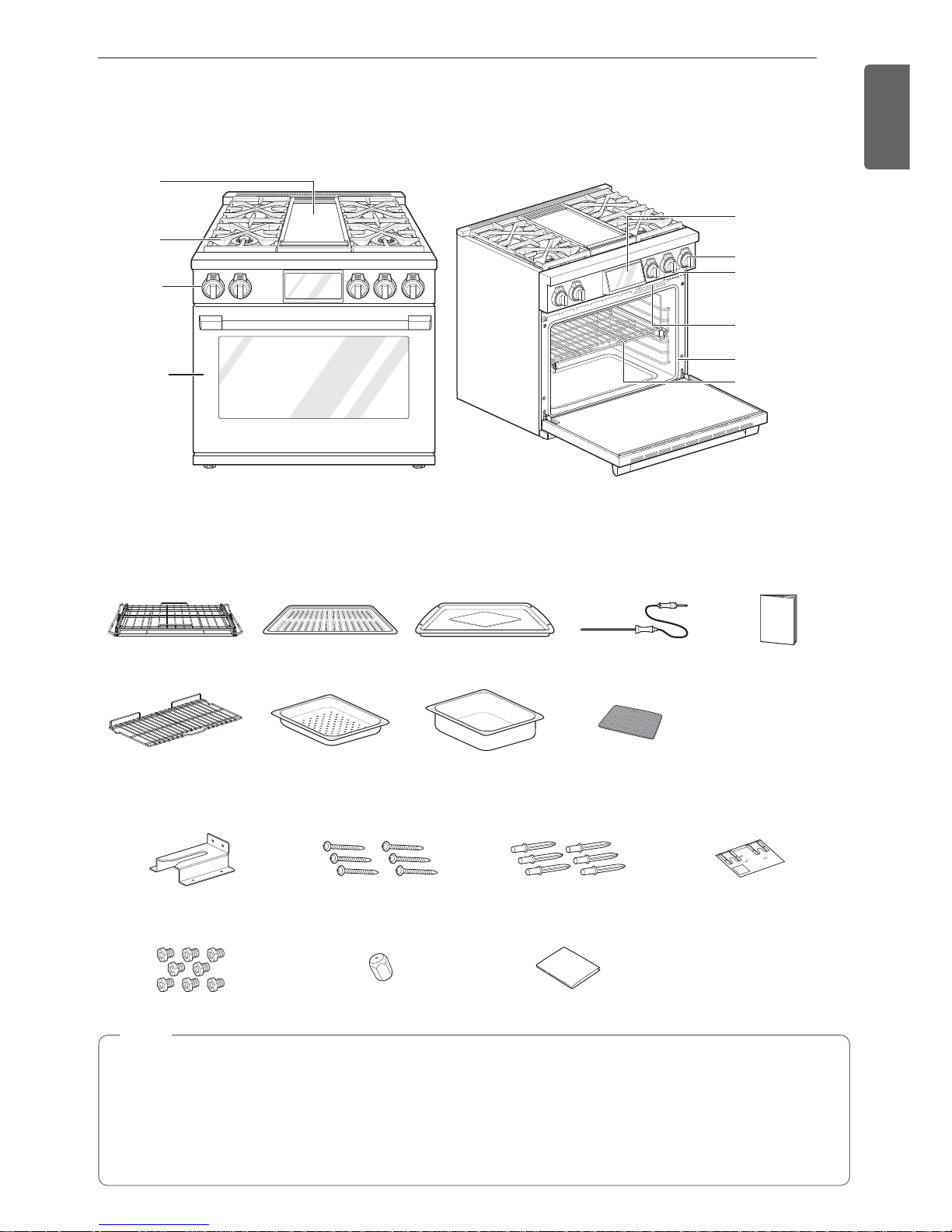
Parts
Cooktop control
knob
Display Panel
Gasket
Steam Feeder
Tank
Rack
Rating label
model and serial
number plate
Gas
Cooktop
Griddle
Controller
Oven Door
Accessories
Included Accessories
Gliding rack (2ea) Grid (1ea) Broiler pan (1ea) Meat probe (1ea) Owner’s manual
(1ea)
Rack (1ea) Perforated tray
(1ea)
Solid tray
(1ea)
Non-scratch scouring
pad (1ea)
Anti-tip kit
Anti-tip bracket (1ea) Screws (6ea) Anchors (6ea) Template
LP nozzle conversion kit
Cooktop nozzles (8ea) Griddle nozzle (1ea) Installation guide (1ea)
NOTE
%If accessories are missing, call 1-855-790-6655 or visit our website at : www.thesignaturekitchen.com
%For your safety and for extended product life, only use authorized components.
%The manufacturer is not responsible for product malfunction or accidents caused by the use of separately
purchased, unauthorized components or parts.
%The images in this guide may be different from the actual components and accessories, which are subject
to change by the manufacturer without prior notice for product improvement purposes.
14
INSTALLATION
INSTALLATION
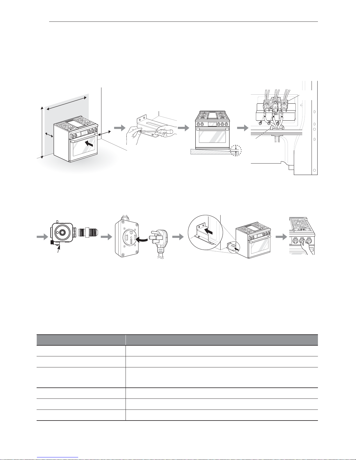
Installation Overview
Please read the following installation instructions first after purchasing this product or transporting it to another
location.
Check and choose the
proper location
Install anti-tip device Level the range Connect electric range
Conduit
connection
plate
Black White Red
Terminal
block
Plug in the power cordConnect the range to gas Engage the anti-tip device Test run
240 V or 208 V
Pressure regulator
Product Specifications
The appearance and specifications listed in this manual may vary due to constant product improvements.
Oven Range Models SKSDR360GS
Description 36" Duel Fuel Pro Range
Electrical requirements 6.4 kW 120/240 VAC, 4.8 kW 120/208 VAC
Exterior Dimensions
35 7/8" (W) x 35 7/64" (H) x 26 39/64" (D) (D with door closed)
91.1 cm (W) x 89.6 cm (H) x 67.6 cm (D) (D with door closed)
Height to cooking surface 36" (91.4 cm)
Net weight 396.8 lb (180 kg)
Total capacity 6.3 cu.ft.
15
INSTALLATION
ENGLISH
Before Installing the Range
WARNING
Tip - Over Hazard
A child or adult can tip the range and
be killed. Verify the anti-tip bracket
has been installed. Ensure the
anti-tip bracket is engaged when the
range is moved.
Do not operate the range without the
anti-tip bracket in place. Failure to
follow these instructions can result
in death or serious burns to children
and adults.
To check that leveling leg is
inserted into anti-tip bracket,
grasp the top rear edge
of the range and carefully
attempt to tilt it forward.
Anti-tip
bracket
Leveling
leg
WARNING
%Leveling legs must be extended lower than
wheels to prevent range from moving.
This range is designed with wheels to make
installation easier. During installation, make
sure to extend the leveling legs until the wheels
are lifted off the ground. Failure to do so can
result in death or serious injury to children and
adults.
If you did not receive an anti-tip bracket with your
purchase, call 1-855-790-6655 (SIGNATURE
KITCHEN SUITE) to receive one at no charge.
WARNING
%The information in this manual should be
followed exactly. Failure to do so may result
in fire, electrical shock, property damage,
personal injury, or death.
%Wear gloves during the installation
procedure. Failure to do so can result in bodily
injury.
%Make sure no parts came loose during shipping.
In the Commonwealth of Massachusetts
%This product must be installed by a licensed plumber or gas fitter.
%When using ball type gas shut-off valves, they must be the T-handle type.
%When using a flexible gas connector, it must not exceed 3 feet in length.
NOTE
%Observe all governing codes and ordinances.
%Have the installer show you the location of the circuit breaker or fuse. Mark it for easy reference.
%As when using any appliance generating heat, follow basic safety precautions.
%Be sure your range is installed and grounded properly by a qualified installer or service technician
according to the installation instructions.
%Any adjustment and service should be performed only by qualified gas range installers or service
technicians.
16
INSTALLATION
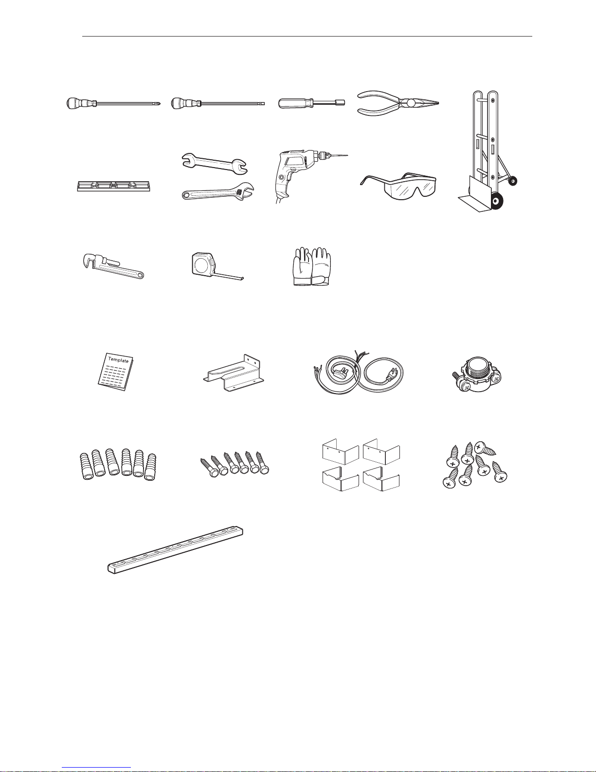
Preparing for Installation
Tools Needed
Phillips screwdriver Flat-blade screwdriver
1
/4" Nut driver Pliers
Level Open-end or
adjustable wrench
Drill Safety glasses Dolly
Pipe wrench (2)
(one for support)
Tape measure Gloves
Parts Provided Parts not Provided
Template (1) Anti-tip bracket kit (1) 4-wire or 3-wire cord and
strain relief kit
(UL approved 40 or 50 AMP)
Strain relief
(For conduit
Installations only)
Anchor sleeves (6) Lag bolts (6) Leg cover (2 sets) Screws (7)
(Leg cover, Front rail)
Front rail (1)
Materials You May Need
%Gas line shut-off valve
%Pipe joint sealant that resists action of natural and LP gases
%Flexible metal appliance connector (
3
/4" or 1/2" NPT x 1/2" I.D.)
Never use an old connector when installing a new range.
%Flare union adapter for connection to gas supply line (
3
/4" or 1/2" NPT x 1/2" I.D.)
%Flare union adapter for connection to pressure regulator on range (
1
/2" NPT x 1/2" I.D.)
%Liquid leak detector or soapy water
%Lag bolt or
1
/2" O.D. sleeve anchor (for concrete floors only)
17
INSTALLATION
ENGLISH
Ventilation Requirement
It is recommended that these ranges be installed in
conjunction with a suitable overhead vent hood.
%Install a hood with at least 600 CFM above a 30” or
36” range.
Due to the high heat capacity of this unit, particular
attention should be paid to the hood and ductwork
installation to assure it meets local building code.
WARNING
Do not install this product with an air curtain hood
or other range hood that operates by blowing air
down on the cooktop. This airflow may interfere
with operation of the gas burners resulting in fire
or explosion hazard.
See below for the minimum clearance from the
cooking surface to any horizontal surface above
the range. Failure to observe this clearance may
result in a fire hazard.
%Installations without a hood require a 48"
minimum distance to any overhead combustible
surface.
%Installations with custom hoods containing
exposed horizontal combustible surfaces
require a hood with at least 600 CFM at least
36" above the cooking surface.
%For other hood installations, refer to the
installation instructions included with the hood
for specific clearances.
Proper Location
%The range is a free standing unit. If the unit is to be
placed adjacent to cabinets, the clearances shown
in “Install Clearance” are required. The same
clearances apply to island installations, except for
overhead cabinets, which must have a space wide
enough to accept the flared island hood.
%The range should not be recessed into the cabinets
beyond the edge of the front face of the oven. (see
“Product Dimensions and Clearances”)
%The maximum depth of overhead cabinets
installed on either side of the hood is 13”(330 mm).
Wall cabinets must be 18” (457 mm) above the
countertop.
%There is a 36'' (914 mm) minimum clearance
required between the top of the cooking surface
and the bottom of an unprotected cabinet. A 30''
(762 mm) clearance can be used when the bottom
of the wood or metal cabinet is protected by not
less than 1/4'' (6 mm) of a flame retardant material
covered with not less than No. 28 MSG sheet steel,
0.015'' (0.38 mm) thick stainless steel, 0.024'' (0.61
mm) aluminum, or 0.02'' (0.51 mm) thick copper.
%Non-combustible surfaces: as defined in 'National
Fuel Gas Code'(ANSI Z223.1, Current Edition).
Clearances from non-combustible materials are not
part of the ANSI Z21.1 scope and are not certified
by UL. Clearances of less than 36 inches (914.4
mm) must be approved by the local codes and/or
by the local authority having jurisdiction.
CAUTION
%Avoid placing cabinets above the range. To
minimize the hazard caused by reaching over
the open flames of operating burners, install a
ventilation hood over the range that projects
forward at least five inches beyond the front of
the cabinets.
%Do not locate your range where it may be
subject to strong drafts. Any openings in the
floor or wall behind the range should be sealed.
Make sure the openings around the base of
the range that supply fresh air for combustion
and ventilation are not blocked by carpeting or
woodwork.
%This range is for indoor, household use
only.
%If the range is located near a window, do not
hang long curtains or paper blinds on that
window.
%Make sure wall covering, countertop and
cabinets around the range can withstand
the heat (up to 194 °F) generated by the
range. Discoloration, delamination or melting
may occur. This range has been designed to
comply with the maximum allowable wood
cabinet temperature of 194 °F.
%Before installing the range in an area
covered with linoleum or other synthetic
floor covering, make sure the floor covering
can withstand temperatures of at least
160 °F.
%Use an insulated pad or
1/4
in. (640 mm)
plywood under the range if installing the
range over carpeting.
When the floor covering ends at the front of the
range, the area that the range will be installed on
should be built up with plywood to the same level
or higher than the floor covering. This will allow the
range to be moved for cleaning and servicing, as well
as provide proper air flow to the range.
18
INSTALLATION
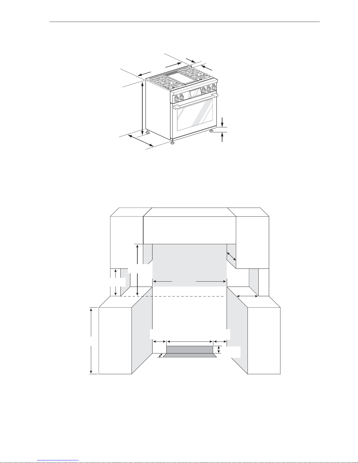
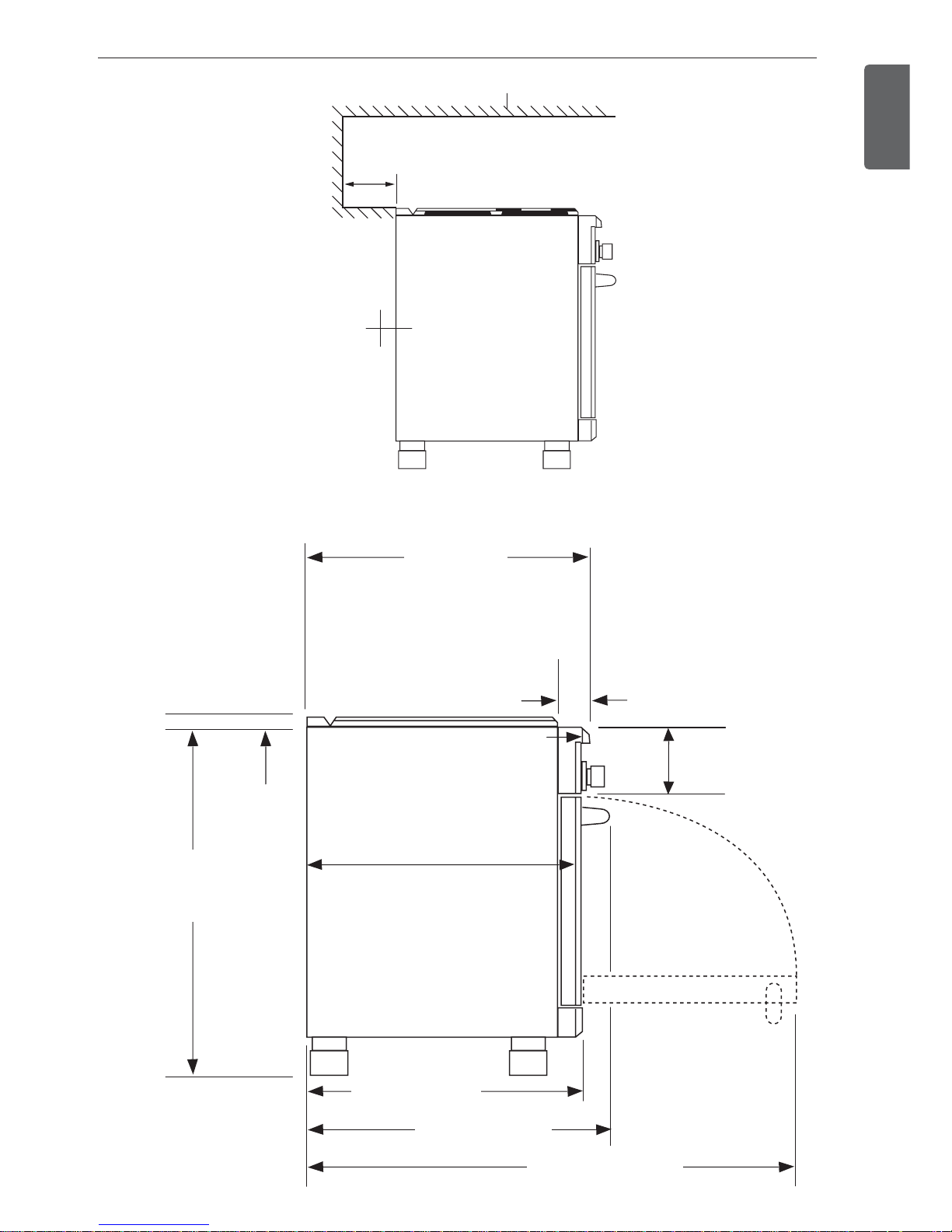
Install Clearance
35 7/64"
(895.7 mm)
to
36 45/64"
(932.3 mm)
Height
2 19/64"
(58.1 mm)
to
3 47/64"
(94.7 mm)
35 7/8"
(911 mm)
Width
1
1
/16"
(26.8 mm)
26 39/64"
(675.7 mm)
Depth to front deco
Countertop
to cooking
surface
Leg height
Universal Utility Locations
3 5/16"
(84 mm)
21"
(533.4 mm)
Gas /Electrical Zone
7 1/2"
(190.5 mm)
7 1/2"
(190.5 mm)
36"
(914.4 mm)
7 5/8"
(193 mm)
10" (254 mm)
13"
(330.2 mm)
36"
(914.4 mm)
18"
(457.2 mm)
36"
(914.4 mm)
Non-Combustible Material
19
INSTALLATION
ENGLISH
3" (76.2 mm) min
to combustible surface with Flush Island Trim
Combustible Materials
0" Clearance
to a back or
side wall below
the cooking
surface
Product Dimensions and Clearances
3.42" (87 mm)
Control Panel
Depth
35
7
/
64
"
(895.7 mm)
to
36
45
/64"
(932.3 mm)
1
1
/16"
(26.8 mm)
28
7
/
8
" (733.4 mm)
To Front Edge
24.4" (620 mm)
Max. recess depth
26 39/64" (675.7 mm)
To Front of Door
29.1" (740 mm)
To Front of Handle
50" (1270 mm)
With Oven Door Open
7.59" (193 mm)
Control Panel
Height
20
INSTALLATION
Gas Supply
The range is designed to operate at a pressure of
5" of water column on natural gas or 10" of water
column on LP.
Make sure you are supplying the range with the type
of gas for which it is configured.
This range is convertible for use with natural or LP
gas. When using this range with LP gas, conversion
must be made by a qualified LP installer before
attempting to operate the range.
For proper operation, the pressure of natural gas
supplied to the regulator must be between 5" and 13"
of water column.
For LP gas, the pressure supplied to the regulator
must be between 10" and 13" of water column. When
checking for correct operation of the regulator, the
inlet pressure must be at least 1" more than the
operating (manifold) pressure as given above.
The pressure regulator located at the inlet of the
range must remain in the supply line regardless of
which type of gas is being used.
A flexible metal appliance connector used to connect
the range to the gas supply line should have an I.D.
of
5
/8" and a maximum length of 5 feet. In Canada,
flexible connectors must be single wall metal
connectors less than 6 feet in length.
Electrical Supply
Installation of the range must be planned so that the
rough in of the terminal block for the receptacle or
conduit connection will allow maximum clearance to
the rear of the unit.
When the power supply cord or conduit is connected
to the mating receptacle or terminal block cover, the
combined connection should protrude no more than
2'' (51 mm) from the rear wall.
NOTE
Canadian models have the power cord supplied
with the range.
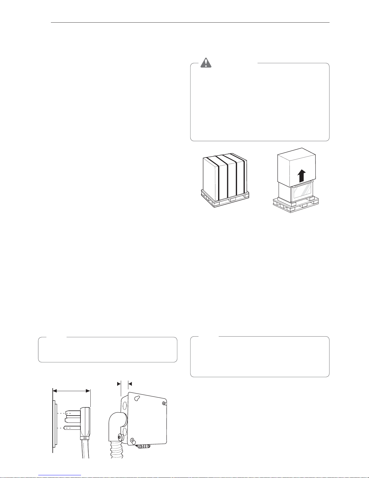
Power Cord & Receptacle
2" (51 mm) maximum
when plugged in
Junction Box & Conduit
2” (51 mm)
maximum
Installing the Range
Unpacking the Range
CAUTION
%You should use 2 or more people to move
and install the range. (Excessive Weight
Hazard) Failure to do so can result in back or
other injury.
%Do not use the door handles to push or
pull the range during installation or when
moving the range out for cleaning or
service. Doing so can result in serious damage
to the door of the range.
1
Cut the packing straps. Lift the carton straight
up. Remove packing material, tape and any
temporary labels from your range before using
but leave the adhesive-backed foam layer over
the brushed-metal surface, to protect the finish
from scratches. Do not remove any warning-type
labels, the model and serial number label, or the
Tech Sheet that is located on the back of the
range.
2
Remove the door(s). This will reduce the weight
of the range during installation.
3
The grates, burner heads, burner caps, trays
and oven racks must be removed to facilitate
handling. Do not remove the griddle element.
NOTE
Doors and passageways leading to the installation
location require at least 32" (813 mm) opening. If
the opening is less than 32" (813 mm), the oven
door(s) and control knobs must be removed.
21
INSTALLATION
ENGLISH
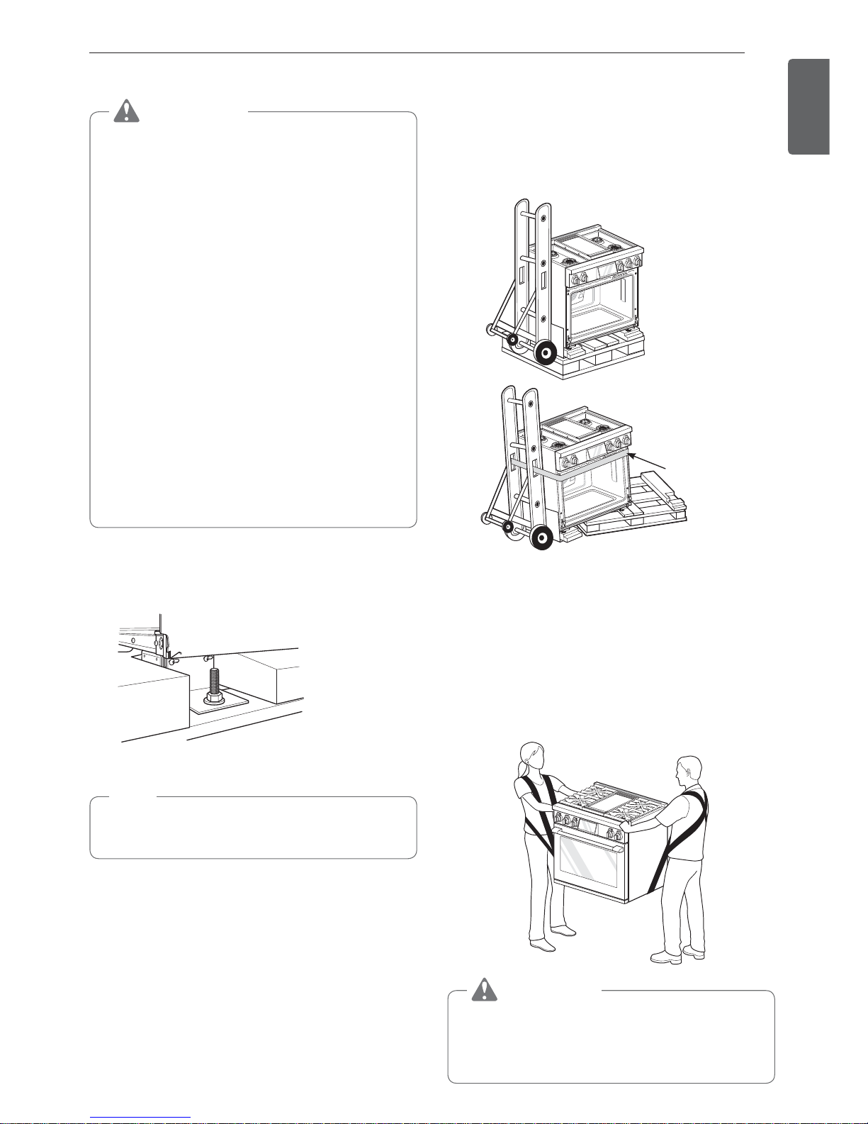
Moving the Range
CAUTION
%Do not lift the range by the oven door’s handle,
as this may damage the door hinges and cause
the door to fit incorrectly.
%Do not lift the appliance by the range’s control
panel.
%Rings, watches, and any other loose items
that may damage the unit or otherwise might
become entangled with the unit should be
removed.
%Hidden surfaces may have sharp edges. Use
caution when reaching behind or under the
appliance.
%Do not use a hand truck or appliance dolly on
the back or front of the unit. Handle from the
side only.
%Due to the weight, it is strongly recommended
that a furniture dolly with soft wheels or an air
lift be used to move this unit. The weight must
be supported uniformly across the bottom.
%All ranges are held to the pallet by (4) brackets
through a wood block
1
Remove the two screws on each bracket that
secure the product to the pallet.
2
Remove the oven door and racks.
NOTE
%Instructions for removing the oven doors can be
found on page 74.
3
Carefully tilt the range from the side and insert a
dolly under the range to remove the range from
the pallet. Use additional help as required to
remove the product from the pallet. To prevent
damage to the sides of the range, it will be
necessary to pad the corners beneath the straps
on the dolly.
Dolly Straps
Below Oven
4
Transport the range on the furniture dolly close
to its final location, tip the range back to level,
and carefully remove the dolly.
Your range is heavy and can be installed on soft
floor coverings such as cushioned vinyl or carpeting.
Use care when moving the range on this type of
flooring. Use a belt when moving the range to prevent
damaging the floor. Or slide the range onto cardboard
or plywood to avoid damaging the floor covering.
CAUTION
%You should use two or more people to move
and install the range. (Excessive Weight
Hazard) Failure to do so can result in back or
other injury.
22
INSTALLATION
Installing the Anti-tip Device
Anti-tip
bracket
Leveling
leg
WARNING
Tip - Over Hazard
A child or adult can tip the range and
be killed. Verify the anti-tip bracket
has been installed. Ensure the anti-tip
bracket is engaged when the range
is moved. Do not operate the range
without the anti-tip bracket in place.
Failure to follow these instructions
can result in death or serious burns to
children and adults.
To check that leveling leg is
inserted into anti-tip bracket,
grasp the top rear edge
of the range and carefully
attempt to tilt it forward.
Wall plate
Anti-tip
bracket
Screw must
enter wood or
concrete
Locate the anti-tip bracket using the template.
An anti-tip bracket is packaged with the template.
The instructions include necessary information to
complete the installation. Read and follow the range
installation instruction sheet (template).
WARNING
%A child or adult can tip the range and be killed.
%Install the anti-tip device to the structure and/
or the range. Verify the anti-tip device has been
properly installed and engaged by following the
instructions on this template.
%Engage the range to the anti-tip device
following the instructions on this template.
Ensure the anti-tip device is reengaged when
the range is moved by following the instructions
on this template.
%Re-engage the anti-tip device if the range is
moved. Do not operate the range without the
anti-tip device in place and engaged.
%See installation instructions for details.
%Failure to do so can result in death or serious
burns to children or adults.
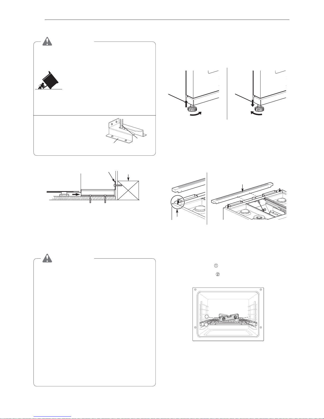
Leveling the Range
Front Legs
Level the range by adjusting the leveling legs with a
wrench. Extending the legs slightly may also make it
easier to insert the rear leg into the anti-tip bracket.
Rear Legs
To adjust the rear leveling legs, remove the 2 screws
at the front of the vent trim and remove the trim.
Use an adjustable 7 mm box wrench to turn the rear
leg extension rods at each corner.
Vent T rim
Rear Leg
Extension Rod
Use a level to check your adjustments. Place the level
diagonally on the oven rack, and check each direction
for level.
First check direction
.
Then check direction
. If the level doesn’t show level
on the rack, adjust the leveling legs with a wrench.
1
2
23
INSTALLATION
ENGLISH
Installing the Leg Cover
1
Remove the plastic covers from the stainless
steel leg covers.
2
Slide each small leg cover inside a larger leg
cover. Cutouts should face up and both covers
should be open at the back.
3
Use the assembled covers to conceal the front
leveling legs.
4
Place the outer covers on the floor and slide the
inner covers up until the holes at the top front
snap over the dimples on the flanges on the
bottom of the range.
Dimples
5
Insert the provided screws through the holes
in the leg cover assemblies to secure them in
place.
Installing Front Rail
1
Remove the plastic film from the stainless steel
front rail.
2
Insert the front rail onto the flange below the
oven door, aligning the holes in the top of the rail
with the holes in the flange.
Front Deco
Flange
3
Use the 3 screws provided to secure the front
rail to the flange.
24
INSTALLATION
Connecting the Range to Gas
Shut off the range gas supply valve before removing
the old range and leave it off until the new hook-up
has been completed.
Because hard piping restricts movement of the range,
a CSA International-certified flexible metal appliance
connector should be used unless local codes require
a hard-piped connection.
A manual valve must be installed in an accessible
location in the gas piping external to the appliance
for the purpose of turning on or shutting off gas to the
appliance.
Never reuse an old connector when installing a new
range.
To protect against gas leaks, use a qualified pipe joint
sealant on all external threads.
1
An inlet pipe is set on the left rear of this
appliance. Hook up a gas hose that has 1/2" NPT
internal thread to the inlet pipe using a wrench.
2
Apply sealing compound or Teflon tape at the
connection.
3
When all connections have been made, be sure
all range controls are in the Off position and turn
on the main gas supply valve. Gas leaks may
occur in your system and create a hazard. Gas
leaks may not be detected by smell alone.
Check all gas connection joints and fittings for
leaks with a non-corrosive leak detection fluid,
then wipe off.
Gas suppliers recommend you purchase and
install a UL approved gas detector. Install
and use in accordance with the installation
instructions.
WARNING
%Do not use a flame to check for gas leaks.
%Isolate the range from the gas supply system
by closing its individual shut-off valve during
any pressure testing of the gas supply system
at test pressures equal to or less than
1
/2" psig
(3.5 kPa).
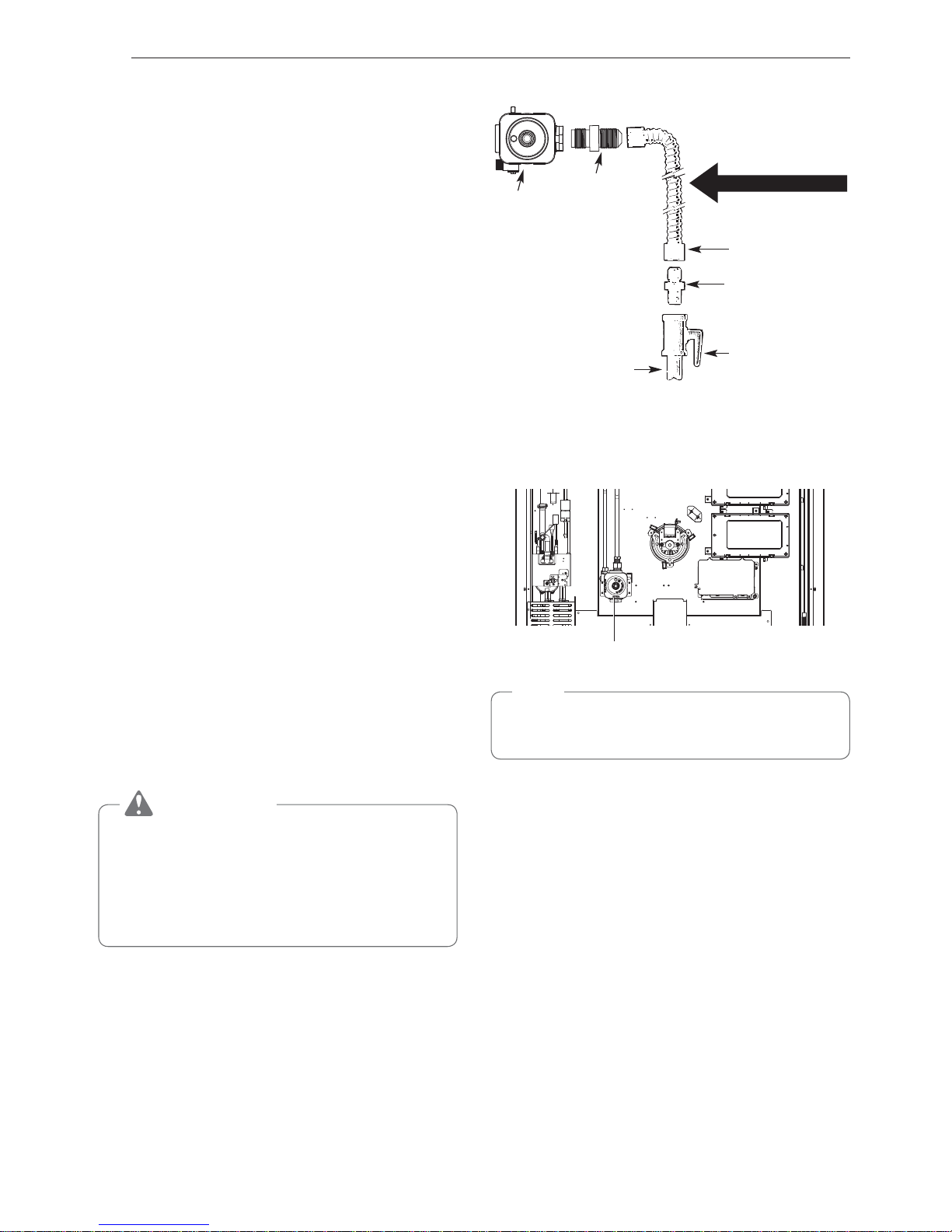
Flexible Connector Hookup
1
/2"
Adapter
Pressure regulator
Flex connector
(6 ft. max.)
Adapter
Gas shut-off
valve
1
/2" or 3/4" Gas
pipe
Gas Flow into Range
Installer: Inform the consumer of the location of the gas
shutoff valve
.
Pressure Regulator Position
Pressure Regulator
NOTE
Use a coin to unscrew the circular cap on the
pressure regulator.
25
INSTALLATION
ENGLISH
Connecting Electricity
Electrical Requirements
This appliance must be installed and grounded on a
branch circuit by a qualified technician in accordance
with the National Electrical Code ANSI/NFPA NO. 70
- latest edition.
All wiring should conform to local and NEC codes.
This range requires a single-phase, 3 wire, A.C
120/208 V or 120/240 V 60 Hz electrical system. Use
only a 3-conductor or a 4-conductor UL-listed range
cord with closed-loop terminals, open-end spade
lugs with upturned ends or similar termination. Do not
install the power cord without a strain relief.
A range cord rated at 40 amps with 120/208 or
120/240 minimum volt range is required. If a 50 amp
range cord is used, it should be marked for use with
1
3
/8" diameter connection openings. This appliance
may be connected by means of a conduit or power
cord. If a conduit is being used, go to page 27 for
3 wire conduit connections or 4 wire conduit
connections.
WARNING
%Allow 2 to 3 ft (61.0 cm to 91.4 cm) of slack
in the line so that the range can be moved if
servicing is ever necessary.
%The power supply cord and plug should not
be modified. If the plug will not fit the outlet,
have a proper outlet Installed by a qualified
electrician.
%Using an extension cord to connect the
power is prohibited. Connect the power cord
and plug directly.
%Electrical ground is required on this
appliance.
%Make sure that the power cord is not pinched
by the range or heavy objects. Failure to
do so can result in serious burns or electrical
shock.
%Do not use a damaged power plug, power
cord, or loose power outlet.
%Do not put a fuse in a neutral or ground
circuit.
%Do not connect the ground wire to plastic
plumbing lines, gas lines, or hot water pipes.
Specified power-supply-cord kit rating
Range rating, watts
Specified
rating of
power
supply-
cord kit,
amperes
Diameter
(inches) of range
connection
opening
120/240
volts
3-wire
120/208
volts
3-wire
Power
cord
Conduit
8,750 16,500
16,501 22,500
7,801 12,500
12,501 18,500
40 or 50A
50
1
3
/8"
1
3
/4"
1
1
/8"
1
3
/8"
3, 4 - Wire Electrical Wall Receptacle
4 Wire receptacle (14-50R)
3 Wire receptacle (10-50R)
26
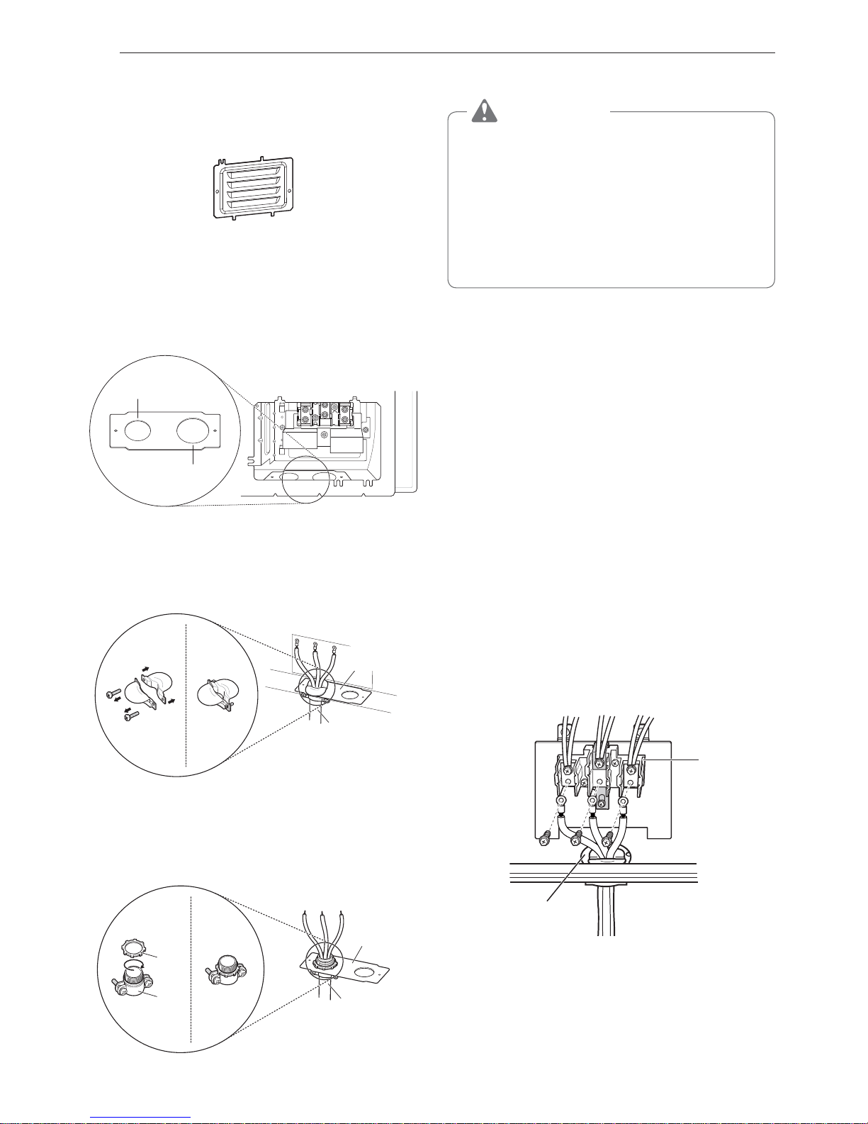
INSTALLATION
Connecting the Power Cord
The rear access cover must be removed. Loosen the
two screws with a screwdriver. The terminal block will
then be accessible.
Access cover
Use the cord/conduit connection plate to install the
power cord or conduit. Leave the connection plate
as installed for power cord installations. Remove the
connection plate for conduit installations and use the
smaller 1
1
/8 in. (2.8 cm) conduit hole instead of the
1
3
/8 in. (3.5 cm) power cord hole.
11/8"
(2.8 cm) Conduit
13/8"
(3.5 cm) Cord
Remove the conduit connection plate
For power cord installations, hook the strain relief
over the 13/8 in. (3.5 cm) power cord hole located
below the rear of the oven. Insert the power cord
through the strain relief and tighten it.
Conduit
connection
plate
Power cord
Assembling power cord strain relief at the 1
3
/8" opening
For conduit installations, insert the conduit strain
relief in the 1
1
/8 in. (2.8 cm) conduit hole. Then install
the conduit through the body of the strain relief and
fasten the strain relief with its ring.
Cord/
Conduit
connection
plate
Conduit
Ring
Body
Assembling conduit cord strain relief at the 1
1
/8" opening
3-Wire Connection: Power Cord
WARNING
%The middle (neutral or ground) wire, which
is white, of a 3-wire power cord or a 3-wire
conduit has to be connected to the middle
post of the main terminal block. The
remaining two wires of the power cord or
conduit have to be connected to the outside
posts of the main terminal connection block.
Failure to do so can result in electrical shock,
severe personal injury or death.
Installing the Power Cord
For power cord installations, hook the strain relief
over the power cord hole (1
3
/8") located below the
rear of the oven. Insert the power cord through the
strain relief and tighten the strain relief.
Do not install the power cord without a strain
relief.
1
Remove the lower 3 screws from the terminal
block and retain them.
2
Insert one of the screws through each power
cord terminal ring and into the lower terminals
of the terminal block. Make sure that the center
(neutral) wire, which is white, is connected to the
center lower position of the terminal block.
3
Tighten the 3 screws securely into the terminal
block. Do not remove the ground strap
connections.
3-Wire Connection
Black White Red
Terminal
block
Conduit
connection plate
If screws are not tightened securely, it can result in
electrical spark and severe personal injury or death.
27
INSTALLATION
ENGLISH
4-Wire Connection: Power Cord
WARNING
%Only a 4-conductor power-supply cord kit
rated 120/208 or 120/240 volts, 50 amperes
and marked for use with ranges with closedloop connectors or opened spade lugs with
upturned ends must be used.
The white middle (neutral) wire of the power
cord or 4-wire conduit has to be connected
to the middle post of the main terminal
block. The other two wires of the power
cord or conduit have to be connected to
the outside posts of the main terminal
connection block. The 4th ground wire
(green) must be connected to the frame of
the range with the ground screw. Failure
to do so can result in electrical shock, severe
personal injury or death.
Installing the Power Cord
Do not install the power cord without a strain
relief.
1
Remove the lower 3 screws from the terminal
block and retain them.
2
Remove the ground screw and bend the end of
the ground strap up so the slot is over the hole
of the center screw removed in step 1.
3
Insert the ground screw into the power cord
ground wire (green) terminal ring and secure it to
the range frame.
4
Insert one screw through each power cord
terminal ring and into the lower terminals of the
terminal block. Make sure that the white center
(neutral) wire is connected to the center lower
position of the terminal block.
5
Tighten the 3 screws securely into the terminal
block. The center screw now attaches the bent
up ground strap to the block.
4-Wire Connection
Ground
strap
Terminal
block
Conduit
connection plate
Ground
screw
Black White Red
Bend strap up
and attach
If screws are not tightened securely, it can result in
electrical spark and severe personal injury or death.
3-Wire Connection: Conduit
Installing the Conduit
Remove the conduit connection plate from the rear of
the oven and rotate it. The conduit hole (1
1
/8") must
be used.
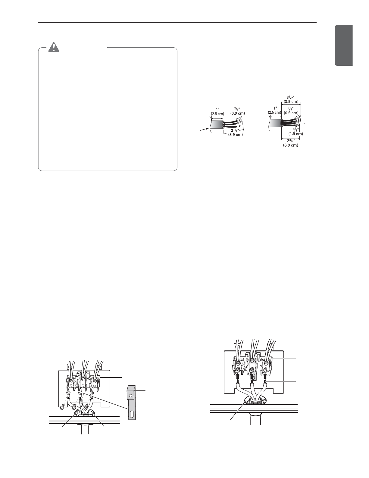
First, prepare the conduit wires as shown below.
3-Wire
Conduit
connection
plate
Ground
wire
or
4-Wire
Second, install the conduit strain relief.
For conduit installations, purchase a strain relief and
insert it in the 1
1
/8 in. (2.8 cm) conduit hole. Then
install the conduit through the body of the strain relief
and fasten the strain relief with its ring. Reinstall the
bracket.
For conduit connections:
If the wire in the conduit is copper it must be 8 or 10
AWG wiring.
If the wire in the conduit is aluminum it must be 6 or 8
AWG wiring.
1
Loosen the lower 3 screws from the terminal
block.
2
Insert the bare wire (white/neutral) end through
the center terminal block opening. Do not
remove the ground strap connections.
3
Insert the two side bare wire ends into the lower
left and the lower right terminal block openings.
Tighten the 3 screws securely into the terminal
block. (approximately 35 - 50 IN-LB)
3-Wire Conduit Connection
Terminal
block
Black White Red
Wire
ends
Conduit
connection plate
If screws are not tightened securely, it can result in
electrical spark and severe personal injury or death.
28
INSTALLATION
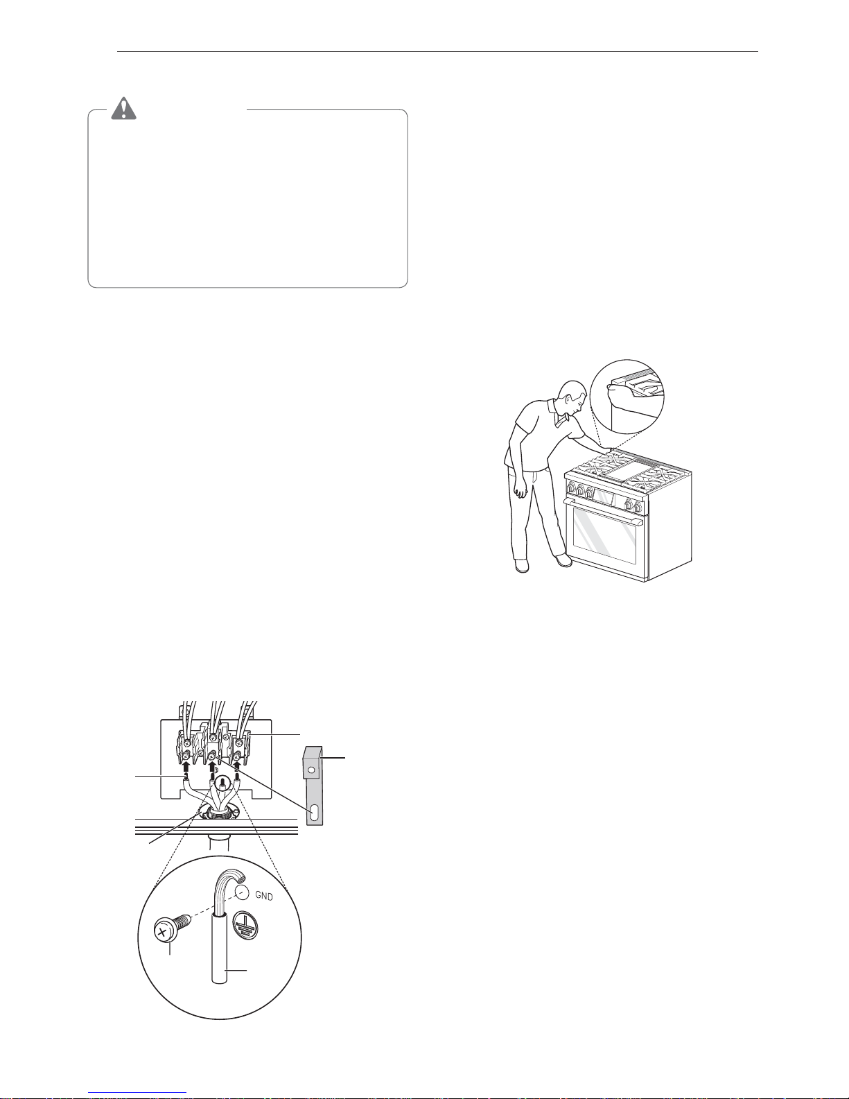
4-Wire Connection: Conduit
WARNING
%The white middle (neutral) wire of the power
cord or 4-wire conduit has to be connected
to the middle post of the main terminal
block. The other two wires of the power
cord or conduit have to be connected to
the outside posts of the main terminal
connection block. The 4th ground wire
(green) must be connected to the frame of
the range with the ground screw. Failure
to do so can result in electrical shock, severe
personal injury or death.
1
Follow the instructions for installing the conduit
under 3-Wire Connection: Conduit until the strain
relief and bracket are installed. Do not install the
conduit without a strain relief.
2
Loosen the 2 lower left and right screws from the
terminal block. Remove the lower center screw.
Do not discard any screws.
3
Remove the ground screw and bend the end of
the ground strap up so the slot is over the hole
of the center screw removed in step 2.
4
Attach the ground (green) bare wire end to the
range frame and secure it in place with the
ground screw.
5
Insert the bare wire (white/neutral) end through the
center terminal block opening. The center screw
now attaches the bent up ground strap to the block.
6
Insert the two side bare wire ends into the left
and the right terminal block openings. Tighten
the 3 screws securely into the terminal block.
(approximately 35 - 50 IN-LB)
4-Wire Conduit Connection
Terminal
block
Black White Red
Ground
strap
Wire
ends
Conduit
connection
plate
Bend strap
up and
attach
Ground
wire
Ground
screw
If screws are not tightened securely, it can result in
electrical spark and severe personal injury or death.
Engaging the Anti-tip Device
%Move the range close enough to the opening to
plug into the receptacle.
%Slide the range into position ensuring that the back
leg slides under the anti-tip bracket. The range
should sit flush against the back wall when properly
installed.
%Carefully attempt to tip the range forward to ensure
that the anti-tip bracket is engaged properly. If
properly installed, the anti-tip bracket will prevent
the range from being tipped. If the range can be
tipped, reinstall the range until the anti-tip bracket is
properly installed and the range will not tip forward.
%Turn on electrical power. Check the range for
proper operation.
29
INSTALLATION
ENGLISH
Test Run
Check if the range is properly installed and run a test
cycle.
1
Remove all packing materials from inside the
oven. Press Power button located next to the
display and set initial settings such as language
and time.
(Refer to "Getting Started" in the Operation
section.)
2
Check the operation of the oven. Select the cook
mode screen opens. Select Bake then Start.
3
The oven should finish preheating in 15 minutes.
4
After making sure the oven operates properly,
turn the temperature in the oven to 550 °F
(288 °C) and leave the oven on for at least an
hour. This helps remove any residual oil which
might cause smoke or odor when first using the
oven.
NOTE
Smoke may come out of the range when it is first
used.
Checking Ignition of the
Surface Burners
Electric Ignition
Select a surface burner knob and simultaneously
push in and turn to the Lite position. You will hear
a clicking sound indicating proper operation of the
spark module.
Once the air has been purged from the supply lines
the burner should ignite within 4 seconds. After the
burner ignites, rotate the knob out of the Lite position.
Try each burner in succession until all burners have
been checked.
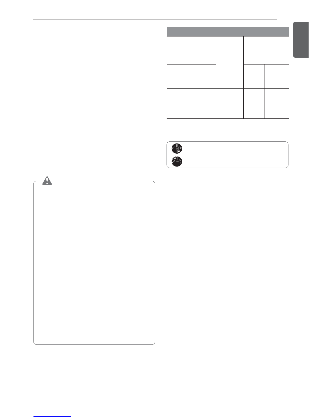
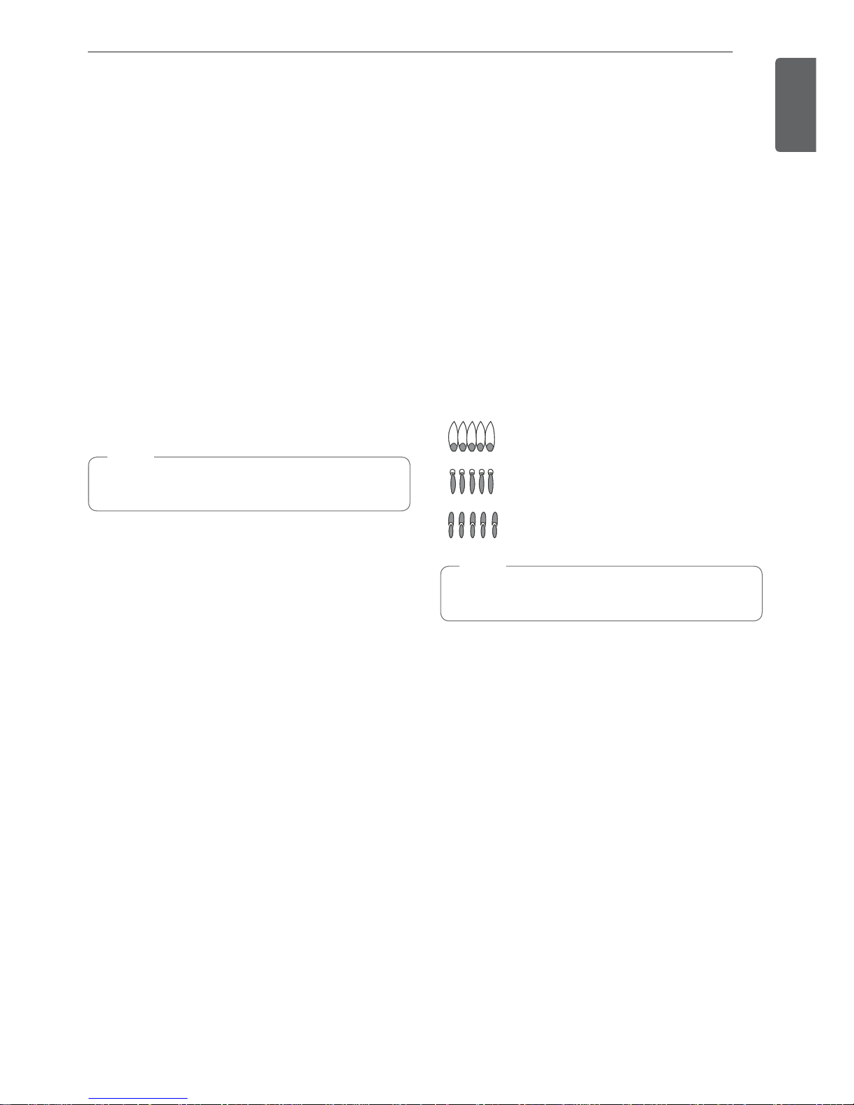
Quality of Flames
The combustion quality of the burner flames needs to
be confirmed visually.
A Yellow flames - Call for service.
B Yellow tips on outer cones - This
is normal for LP gas.
C Soft blue flames - This is normal
for natural gas.
NOTE
%With LP gas, some yellow tipping on outer
cones is normal.
30
INSTALLATION
Adjusting the Surface Burner to the
Low Flame (Simmer) Setting
%The continuous simmer setting needs to be
adjusted on all burners.
%The Extra Low Simmer settings on the small (15K
BTU) burners are adjusted automatically as the
flame cycles off and on.
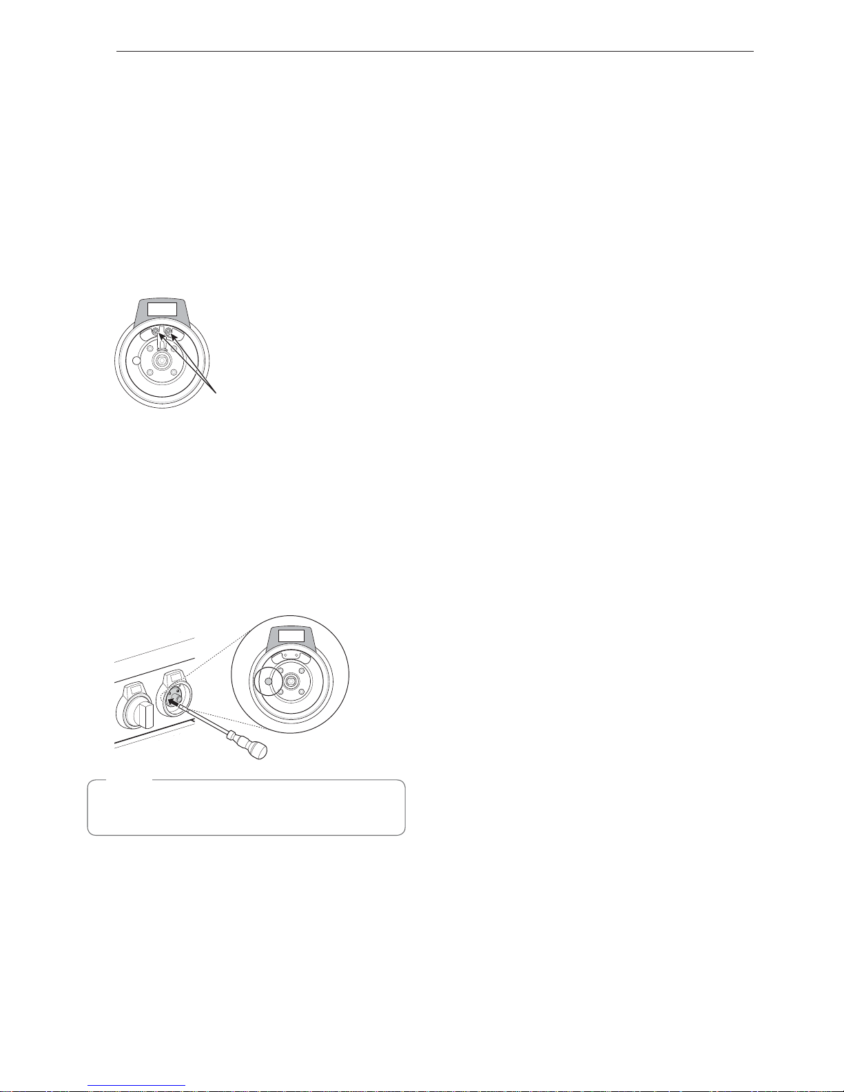
1
Remove the knob on the burner being adjusted.
2
Unscrew the 2 screws to remove the locking
plate.
Screws for locking plate (2ea)
3
Reassemble the burner knob.
4
Light all surface burners.
5
Turn the knob on the burner being adjusted
to the Simmer or S4 position then remove the
knob.
6
Insert a small, flat-blade screwdriver into the
valve shaft and turn the adjustment screw until
the flame reaches the desired size.
NOTE
Hold the valve shaft with one hand while turning
the screw to adjust with the other.
7
Reassemble the locking plate and burner knob.
8
Test the flame stability.
Test 1: Quickly turn the knob from the highest
setting to the Simmer or S4 position. If the flame
goes out, increase the flame size and test again.
Test 2: With the burner set to Simmer or S4,
open and close the oven door quickly. If the air
current extinguishes the flame, increase the
flame height and test again.
9
Repeat steps 1-8 for each gas surface burner.
 Loading...