

Signatrol spYdaq Hardware Manual
Reference : SIG-1227-01-07 Change Note : CN0112
spYdaq Hardware Manual
Page 1 of 36
spYdaq Hardware
Manual.

Reference : SIG-1227-01-07 Change Note : CN0112
spYdaq Hardware Manual
Page 2 of 36
Contents
Contents.................................................................................................................... 2
1 Document History.............................................................................................. 4
2 Introduction........................................................................................................ 5
3 Receiving............................................................................................................ 5
3.1 Transmitters.......................................................................................................... 5
3.2 Base-station .......................................................................................................... 5
3.3 Flow Chart ............................................................................................................. 6
4 Transmitter Set-up............................................................................................. 7
4.1 Setting the device address................................................................................... 7
4.2 Setting the Channel Frequency ........................................................................... 8
4.3 Setting the Transmission Rate............................................................................. 9
The transmission rate determines how often the transmitter takes a measurement
reading and transmits it to the base-station. Most application run on a 10minute
transmit rate which give a battery life in excess of 7 years. Shorter transmit rates
significantly reduce battery life...................................................................................... 9
4.4 Selecting an Appropriate Sensor......................................................................... 9
4.5 Connecting the sensor ....................................................................................... 10
4.6 Positioning the Transmitters.............................................................................. 11
5 PC Software...................................................................................................... 11
5.1 General ................................................................................................................ 11
5.2 Installing the spY-config software..................................................................... 11
6 Modbus Masters .............................................................................................. 11
7 The Base-station.............................................................................................. 12
7.1 Connecting the Base-station.............................................................................. 12
7.2 Optional Auxiliary Power Supply....................................................................... 13
7.3 Wiring the Alarm Connector............................................................................... 14
7.4 Configuration the Base-station.......................................................................... 15
First Use ........................................................................................................................................16
Find Base-station ..........................................................................................................................17

Reference : SIG-1227-01-07 Change Note : CN0112
spYdaq Hardware Manual
Page 3 of 36
Synchronise Clock ........................................................................................................................17
Configure.......................................................................................................................................18
Top Left-System Information .........................................................................................................18
Bottom Left-General Settings ........................................................................................................18
Temperature Units ....................................................................................................................18
Calibration Interval ....................................................................................................................18
Frequency Channel ...................................................................................................................19
Menu Type ................................................................................................................................19
Top Right-Alarm Parameters ........................................................................................................19
System Descriptor .....................................................................................................................19
Top Right – Alarm Settings ...........................................................................................................19
Alarm Latching ..........................................................................................................................19
Audible Annunciation ................................................................................................................19
Transmitter late after .................................................................................................................19
Handle late as ...........................................................................................................................19
Handle Low Bat as ....................................................................................................................20
Bottom Right-Communications Parameters..................................................................................20
IEEE Format.............................................................................................................................. 20
Security .........................................................................................................................................21
Diagnostics....................................................................................................................................22
Basic..........................................................................................................................................22
Advanced ..................................................................................................................................22
Transmitter Configuration.............................................................................................................. 24
General......................................................................................................................................24
Internal Temperature................................................................................................................. 24
Humidity ....................................................................................................................................25
Universal Input ..........................................................................................................................25
Antenna Diversity ..........................................................................................................................25
7.5 Base-Station Controls ........................................................................................ 25
7.6 Base-Station Runtime Screens.......................................................................... 26
Basic Menu....................................................................................................................................26
8 MODBUS RTU Registers ................................................................................. 28
9 Trouble Shooting ............................................................................................. 29
10 Specifications ............................................................................................... 31
10.1
spYdaq Radio Transmitters............................................................................ 31
General..........................................................................................................................................31
10.2
Basestation...................................................................................................... 32
General..........................................................................................................................................32
11 Signal Strength............................................................................................. 33
12 Glossary of Terms........................................................................................ 34
13 System Notes................................................................................................ 35
14 Channel Mapping Template......................................................................... 36

Reference : SIG-1227-01-07 Change Note : CN0112
spYdaq Hardware Manual
Page 4 of 36
1 Document History.
Version Comments
SIG-1227-01-02 Initial Release.
SIG-1227-01-03 Released 27 September 2011
Reading and Alarm block information added.
SIG-1227-01-04 Released 30 November 2011
Added information on Signal Strength
Corrected Signal strength table in section 9,
Basic Diagnostics.
SIG-1227-01-05 Released 08 August 2013
• Add 4 channel information
• Swap switch tables around to LSB first.
SIG-1227-01-06 Added section 11 (Signal Strength)
SIG-1227-01-07 Release 07/06/2017
Changed made for Mk2 Transmitter

Reference : SIG-1227-01-07 Change Note : CN0112
spYdaq Hardware Manual
Page 5 of 36
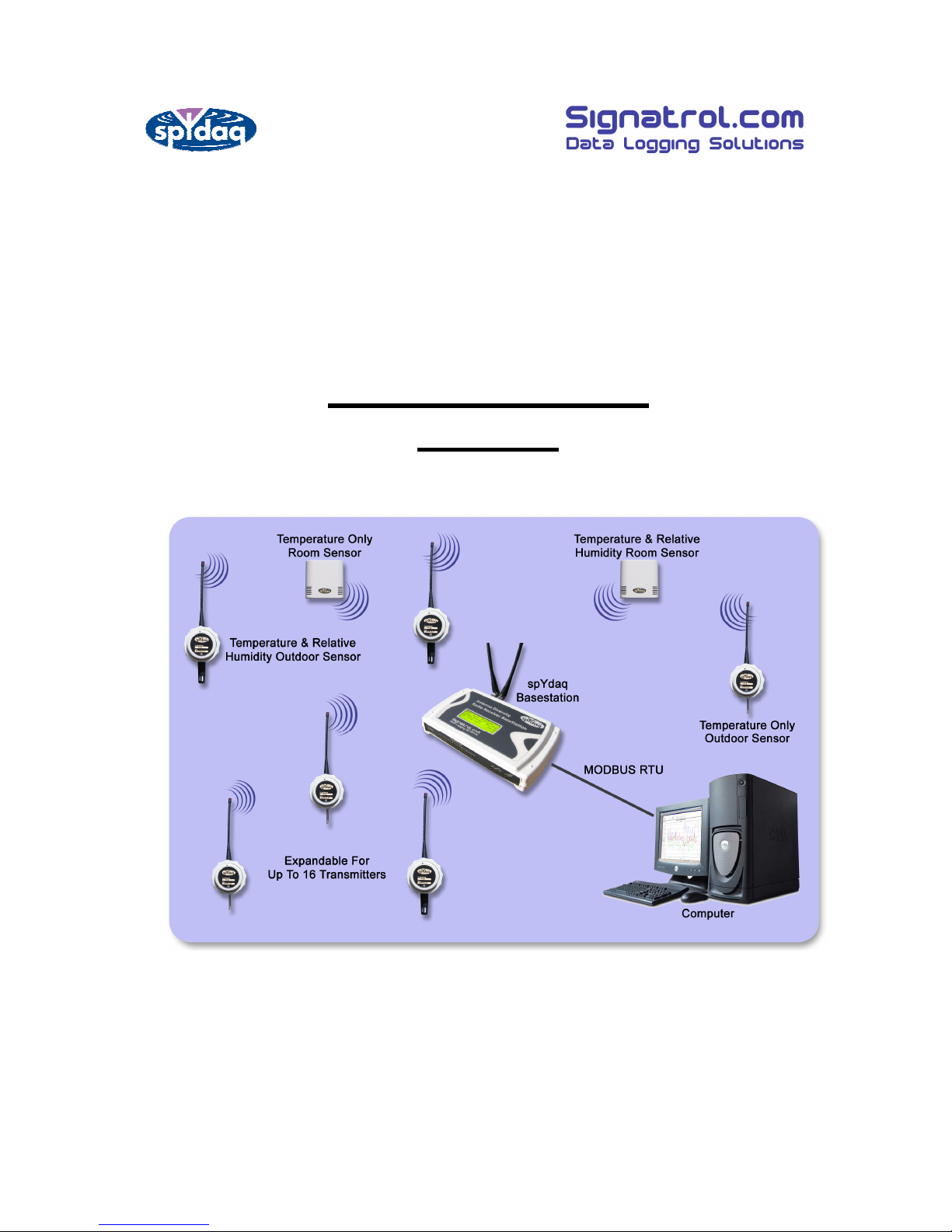
2 Introduction
Congratulations, you have just purchased an advanced radio data logging system. The
following guide takes you through the setting up procedure to enable you to get your
system up and running.
The system comprises of a number of radio transmitters, each with their own address,
which measure various parameters and transmit them to a base station where they are
received, checked for validity and alarms. The parameters are displayed on the local
LCD display and passed either via a serial MODBUS connection to a PC running
appropriate software, or via the mobile phone network (GPRS) to a host website.
There are two frequency channels so that up to two systems can operate side by side.
This manual is only concerned with the MODBUS version.
3 Receiving
Check the box for obvious signs of damage. Is the outer box appears damaged please
do not accept delivery.
Assuming that the system has arrived in good condition then carefully unpack the various
items and check that they are what were ordered.
3.1 Transmitters
If they have been ordered complete with sensors then the sensors should already be
connected and so all that is necessary is to set the address, select the frequency
channel and connect the batteries.
3.2 Base-station
The base-station comes with two standard aerials, a serial interface cable, a USB
interface cable and a power supply with interchangeable plugs. It is necessary to
connect the cables and pre-configure the base-station to enable it to work with the
transmitters
Reference : SIG-1227-01-07 Change Note : CN0112
spYdaq Hardware Manual
Page 6 of 36
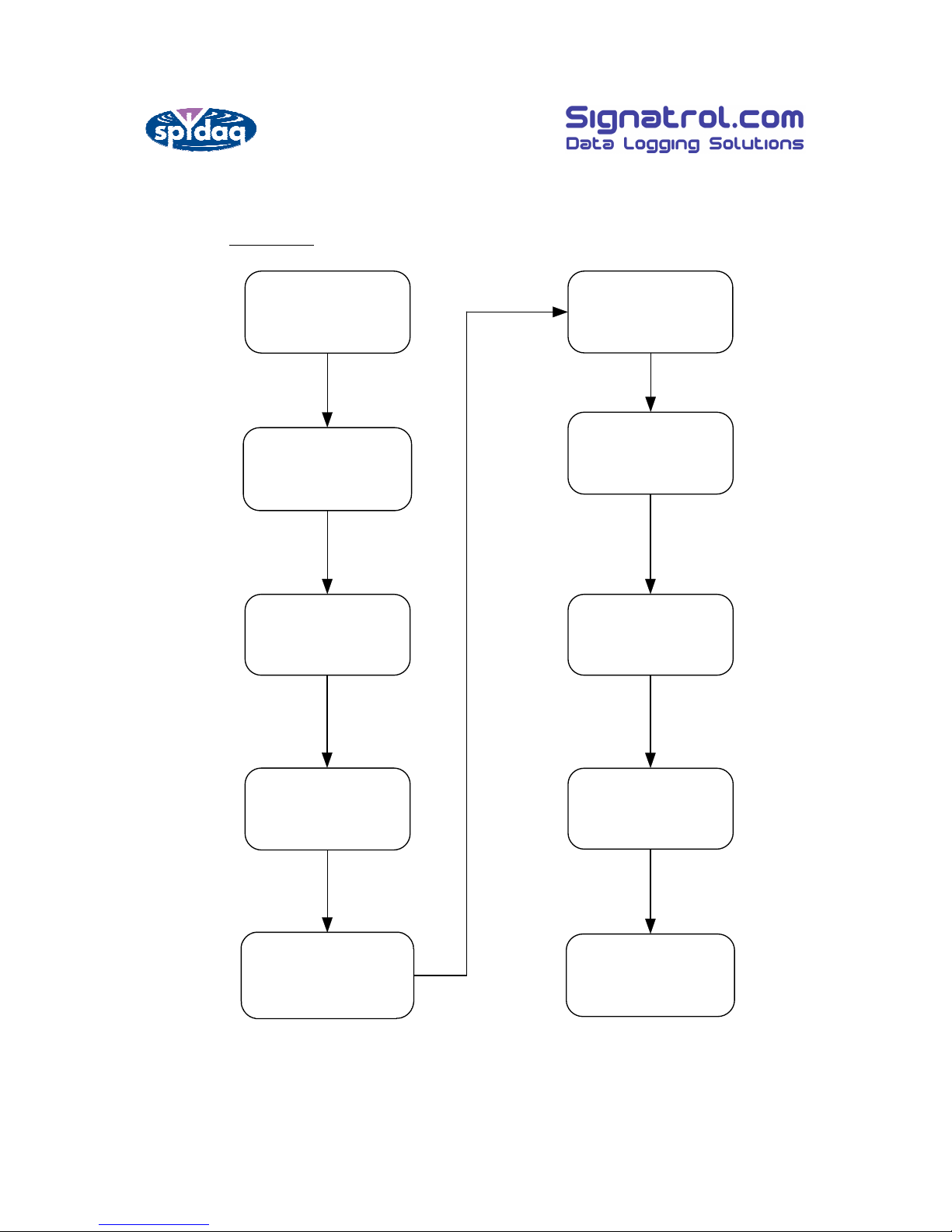
3.3 Flow Chart
Unpack & Check
Contents
Install the
spY- Config
software.
Check the sensors
are attac hed
correctly
Turn ON the
transmitter using the
ON/OFF Switc h
Connect USB cable to
transmitter and c hec k
configuration using
spYc onfig
Connect all cables to
Basestation
Configure
Base-station using
spY- Config Soft ware
Install
spYmonitor-Loc al
Configure data- base
using
spYmonitor-Config
Ensure spYmonitor
Collector is running,
and autost arts when
PC is rebooted.
Reference : SIG-1227-01-07 Change Note : CN0112
spYdaq Hardware Manual
Page 7 of 36
4 Transmitter Set-up
4.1 Setting the device address
Each Base-station can accommodate up to 16 transmitters and each
transmitter can have up to three channels. Temperature, Humidity and
Universal, providing a theoretical maximum of 48 measured points per
system. All transmitters use the same PCB but not all of the transmitters
allow access to all three channels. Consult the individual transmitter
specifications for details.
Before setting the device addresses it is advisable to complete the Channel
Map. Each transmitter is then assigned to a particular area and function. Store the
Channel Map is a safe place for future reference.
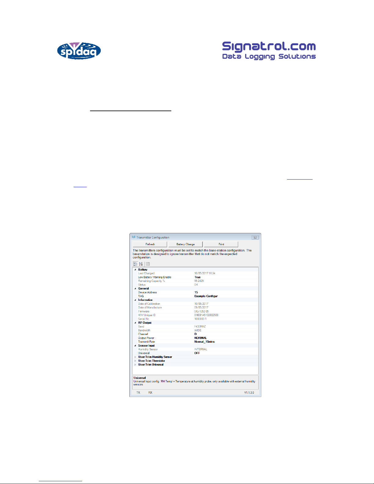
Below is a screen shot of the transmitter configuration screen in the spYConfig application (V1.0.22 or higher required).
Note: Each transmitter must have its own unique address or conflicts will arise
giving false readings. Transmitters must be enabled in the Basestation using the
spYconfig software. Signals arriving at the Basestation which have not been
enabled within the Base-station configuration will be ignored.

Reference : SIG-1227-01-07 Change Note : CN0112
spYdaq Hardware Manual
Page 8 of 36
4.2 Setting the Channel Frequency
Each transmitter can operate on one of four different licence free frequencies. The
channel is selected using the transmitter USB connection and changing the setting
under RF Output>Channel.
Standard Transmitter.
Transmitters with a SPYDAQ-100x prefix.
Channel 433 Band
A
433.55 MHz
B
434.29 MHz
C
433.25 MHz
D
433.92 MHz
Special Order Transmitters.
Transmitters with a SPYDAQ-110x prefix.
Channel 868 Band
A
866.00 MHz
B
867.00 MHz
C
866.33 MHz
D
866.67 MHz
Transmitters with a SPYDAQ-120x prefix.
Channel 915 Band
A
914.50 MHz
B
915.50 MHz
C
922.00 MHz
D
923.00 MHz
Note: whatever frequency is selected for transmission, ALL TRANSMITTERS
MUST BE SET TO THE SAME FREQUENCY and THIS MUST MATCH THE
FREQUENCY SELECTED IN THE BASE-STATION. If the user is using a SPYDAQ
HPR (High Power Repeater) the transmitter frequency channel may differ to the
Base-Station channel due to the repeaters operation.

Reference : SIG-1227-01-07 Change Note : CN0112
spYdaq Hardware Manual
Page 9 of 36
4.3 Setting the Transmission Rate
The transmission rate determines how often the transmitter takes a
measurement reading and transmits it to the base-station. Most application run
on a 10minute transmit rate which give a battery life in excess of 7 years.
Shorter transmit rates significantly reduce battery life.
Transmit Rates
20 Second*
60 Minute 10 Minutes
(default)
30 Minutes
*This mode to be used for setup and commissioning only.
The transmit rate must be the same as the rate set up in the Basestation. Setting
different transmit rates on the transmitter compared to the Base-station will
result in a mis-match error and late alarms/warning.
4.4 Selecting an Appropriate Sensor
Where the transmitter is designed to accept a ‘Universal’ input, it can be one of a
number of different types which are selected as follows:
Available Settings
OFF (Channel Disabled)
RTD/Switch
Thermocouple
0-10 V
0-20 mA
RH Temp *
*RH Temp only available with transmitters fitted with Remote RH
Note: It is important that whatever sensor is selected here is matched by the
configuration of the Base-station. Transmitter signals arriving at the Basestation
with an incorrect configuration will be rejected (See Mismatch error). Please
note that many of the sensors supplied have been pre-configured and need no
further attention.
Reference : SIG-1227-01-07 Change Note : CN0112
spYdaq Hardware Manual
Page 10 of 36
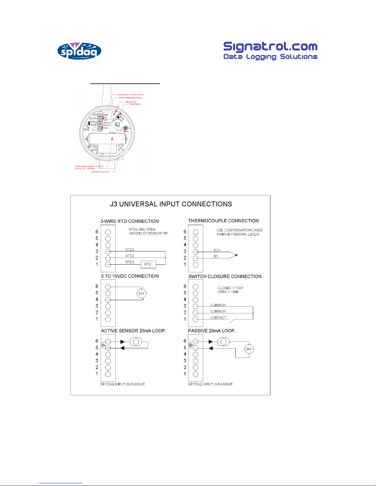
4.5 Connecting the sensor
Having selected an appropriate sensor it then needs to be wired into the PCB as
follows:
Note 1.
4 to 20mA input has an internal impedance of approx 120ohms. The impedance stated
includes the resistance of a series current limiting PTC.
The maximum voltage drop across the spYdaq input is 3V @ 25mA.

Reference : SIG-1227-01-07 Change Note : CN0112
spYdaq Hardware Manual
Page 11 of 36
4.6 Positioning the Transmitters
The performance of radio signals are notoriously difficult to predict due to obstacles,
reflections, interference etc. If there are known issues such as for instance a steel
bulkhead care should be taken in positioning the transmitters and the base-station to
ensure satisfactory transmission signal strength. Positioning of the Base-station aerials
can also have a marked effect on performance see Antenna Diversity.
In general transmitter should be mounted so that the antenna is vertically orientated
and at least 1 metre above ground level. If a particular transmitter is not producing
sufficient field strength then it may benefit from an alternative directional aerial or repositioning. It is for these reasons that, in all but the most simple and straightforward
installations, we would recommend a site survey prior to determining the final
positioning of all the transmitters. Contact the sales office for details.
5 PC Software
5.1 General
For Hardware configuration:
spY-config must be installed on a PC used to setup the spYdaq base-station via USB.
The configuration internal to the base-station must match the transmitter switch
configuration. The user can also setup alarm for each transmitter which will activate
the internal relay and beeper. Customer using spYmonitor has the option to set soft
alarms. Soft alarms can also be set to send emails and/or sms on alarm.
5.2 Installing the spY-config software
Insert the USB drive into your computer and locate the installation exe file.
6 Modbus Masters
The spYdaq base-station has a MODBUS RTU output which is compatible with a wide
range of software platforms, PLCs etc.
We have worked with a number of SCADA systems, including Integraxor, Specview and
Prodigy, but many other systems are available. For more information contact the sales
office.
Modbus is not available on all Base-stations. If you require Modbus make sure that it was
specified on the order. If in doubt, contact our support team.
 Loading...