

Signatrol SL7000 Series, SL7103, SL7001, SL7002, SL7005 User Manual
...
SL7000 User Guide
Drawing No: SIG-1135-01-17 Page 1 of 30
Change Note: CN0054
SL7000 DATA LOGGER
USER GUIDE
Signatrol.com

SL7000 User Guide
Drawing No: SIG-1135-01-17 Page 2 of 30
Change Note: CN0054
Contents
1 INTRODUCTION .............................................................................................................................................................3
1.1 W
ELCOME
....................................................................................................................................................................3
1.2 C
ARE OF THE LOGGER
..................................................................................................................................................3
1.3 U
NDERSTANDING THE HARDWARE CONFIGURATION
...................................................................................................... 3
1.4 S
ERIAL NUMBERING
.....................................................................................................................................................3
1.5 T
HE DIGITAL DISPLAY
...................................................................................................................................................3
1.6 C
HANGING THE BATTERY
..............................................................................................................................................4
1.7 L
OW BATTERY WARNING
. ..............................................................................................................................................4
1.8 B
ATTERY LIFE
...............................................................................................................................................................5
1.8.1
Tips for extending battery life:.........................................................................................................................5
1.8.2
Battery Life for Internal Temperature Only, Internal Humidity and Frequency.............................................. 5
1.8.3
Battery Life including 1 universal channel enabled........................................................................................6
1.8.4
Battery Life including 2 universal channel enabled........................................................................................6
1.8.5
Battery Life including 4 universal channel enabled........................................................................................7
1.9 R
ECALIBRATION
............................................................................................................................................................8
2 SENSOR CONNECTIONS..............................................................................................................................................8
3 EXTERNAL POWER SUPPLY .......................................................................................................................................9
4 EXTERNAL TEMPERATURE/RH SENSOR.................................................................................................................. 9
5 INSTALLING TEMPIT SOFTWARE ...............................................................................................................................9
6 COMMUNICATING WITH THE LOGGER TO THE PC ...............................................................................................10
7 FINDING THE DEVICE ................................................................................................................................................. 11
8 CONFIGURING THE LOGGER.................................................................................................................................... 11
9 REAL TIME DISPLAY...................................................................................................................................................12
10 ISSUING THE LOGGER...............................................................................................................................................12
10.1 F
IRST ISSUE
...............................................................................................................................................................12
10.2 S
ETTING ALARMS
.......................................................................................................................................................12
10.3 P
AGE 1: GENERAL PARAMETERS
................................................................................................................................13
10.4 P
AGE 2: INPUT SETUP
................................................................................................................................................14
10.5 I
NPUT SCALING
:..........................................................................................................................................................15
10.6 C
OUNTER/FREQUENCY INPUT
.....................................................................................................................................16
10.7 P
AGE
3:M
ANIFEST TEXT
.............................................................................................................................................17
10.8 P
AGE 4: INPUT TRIM
...................................................................................................................................................17
11 STARTING THE MISSION............................................................................................................................................17
11.1 S
OFTWARE START
......................................................................................................................................................17
11.2 S
TART ON EVENT
........................................................................................................................................................ 17
11.3 S
TART ON MAGNETIC SWIPE
. ......................................................................................................................................17
12 DOWNLOADING DATA ................................................................................................................................................17
12.1 T
O DOWNLOAD DATA
:..................................................................................................................................................18
13 DISPLAYING A PREVIOUSLY STORED FILE ............................................................................................................18
14 SECURITY TIE ..............................................................................................................................................................18
15 APPENDIX.....................................................................................................................................................................19
15.1 SL7000 S
PECIFICATION
.............................................................................................................................................19
15.1.1
15.1.115.1.1
15.1.1
Inputs .............................................................................................................................................................19
15.1.2
Block Diagram...............................................................................................................................................20
15.1.3
15.1.315.1.3
15.1.3
Accuracies.....................................................................................................................................................21
15.1.4
Measurement Ranges...................................................................................................................................23
15.1.5
General Specification....................................................................................................................................23
15.1.6
Mechanical Dimensions................................................................................................................................24
15.1.7
Optional IP65 Weather-Proof Enclosure. .....................................................................................................25
15.1.8
SL7000 Connection Overview......................................................................................................................26
15.1.9
Current Loop Connection..............................................................................................................................27
15.1.10
Example connection from a Flow transducer with a common collector output...........................................28

SL7000 User Guide
Drawing No: SIG-1135-01-17 Page 3 of 30
Change Note: CN0054
1 Introduction
1.1 Welcome
Welcome to the SL700 data logger from Signatrol Ltd. This flexible and practical logger allows logging of up to 9
variables as follows: 1 internal temperature, 1 internal RH, 4 universal external inputs (Volts, Current,
Thermocouple, RTD or Thermistor), 1 external Temperature, 1 external RH and an external count (frequency) . The
number of channels available is determined by the original configuration and the software settings)
1.2 Care of the logger
The logger is housed in a rugged ABS enclosure. The internal electronics are protected against moisture ingress by
a conformal coating, however, the logger is only designed to work in humid atmospheres of up to 95%RH NonCondensing and should be protected against immersion. It should only be cleaned by wiping with a damp cloth
containing a small amount of detergent.
Warning! Industrial solvents and abrasives can damage the case and the front facia and should not be used for
cleaning.
1.3 Understanding the Hardware Configuration
The configuration supplied is contained within the order code as shown on the rear label as follows:
1st Digit 7 Denotes Series
2nd Digit 0 Denotes no LCD Display, 1 denotes LCD Display fitted
3rd Digit 0 Denotes USB connection to PC
4th Digit 0 Denotes internal temperature Only
1 Denotes internal temperature and RH
2 Denotes 2 Universal Input channels + Internal Temp
3 Denotes 2 Universal Input channels + Internal Temp + RH
4 Denotes 4 Universal Input channels + Internal Temp
5 Denotes 4 Universal Input channels + Internal Temp + RH
The external Temp+ RH probe SL-ACC7000-01 can be fitted to any version.
eg. SL7103 Is a SL7000 series data logger with LCD display, USB interface and two universal inputs together with
an internal temperature and an internal humidity sensor.
1.4 Serial Numbering
Each device has its own unique serial number which identifies the device and enables us to keep a record of its
history. This number is indelibly marked on the front label and also electronically encoded into the device. Please
quote it in any correspondence.
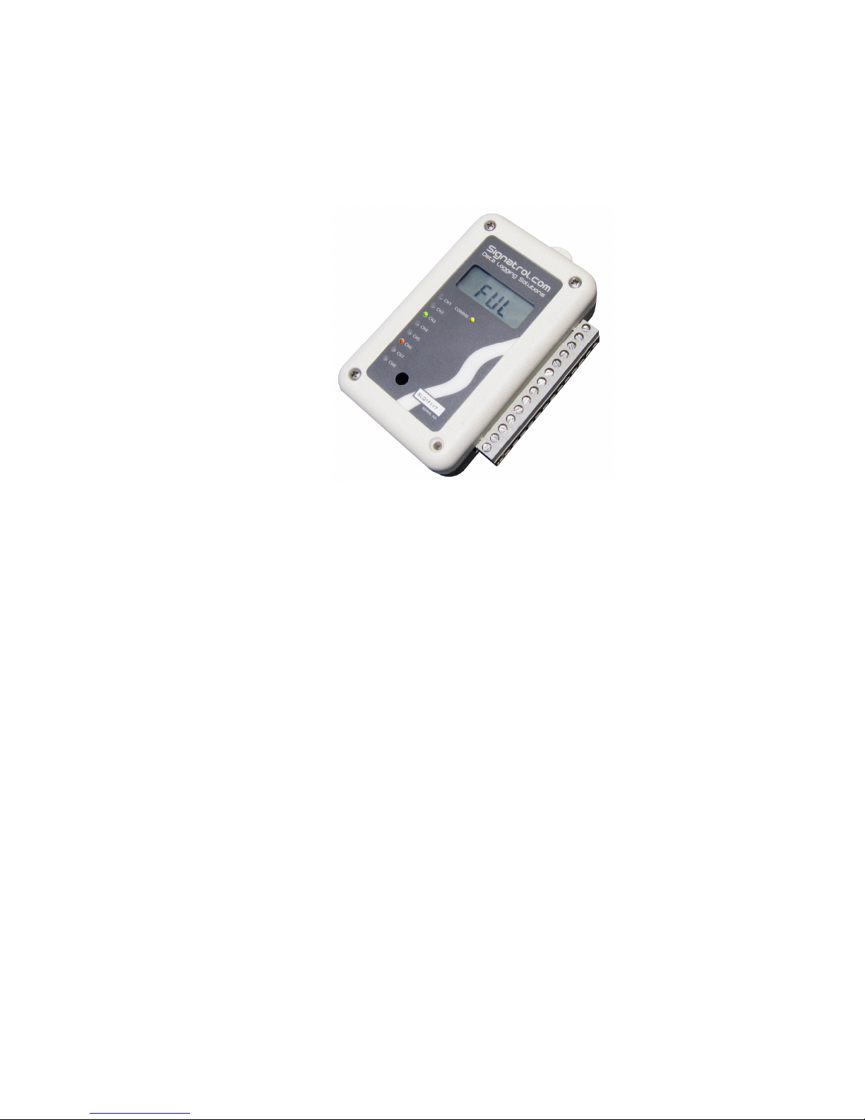
1.5 The Digital Display
The LCD digital display option enables any measured parameter to be displayed digitally. The value together with
its channel number and (in most cases*) its units are displayed. You can select which channels you want to display
from the TempIT software e.g. you may choose to log say 4 channels but only to display 2.
When more than one channel is selected for display the channels are cycled through at the Display Update Rate
which is a programmable interval ( Default 4 Seconds). With each parameter the appropriate channel number is
also displayed.
*Units available are : °C,°F, mA, V, %
LED Displays
A separate LED is provided for each channel. When the channel is selected for logging, the LED flashes at the
Display Update Rate. If the channel is in alarm it flashes RED else it flashes GREEN.
An amber LED is also provided which flashes when the logger is communicating. This LED also flashes
intermittently when the logger is awaiting an event start.

SL7000 User Guide
Drawing No: SIG-1135-01-17 Page 4 of 30
Change Note: CN0054
1.6 Changing the Battery
Although the battery lasts in excess of 6 years (2700mAh battery) with a 2 minute sample rate, when the battery is
nearing the end of its useful life a warning message will be displayed each time you issue the logger. If the device is
fitted with the LCD display option, a small battery symbol also appears in the display. The battery has
approximately 1 month useful life from the logger first indicating a low battery but we recommend that the battery
should be changes as soon as the warning is raised. Changing the battery will result in any data being lost but the
configuration will remain. Remove the 4 stainless steel screws retaining the front half of the case and remove the
front case half. The battery is now exposed and can be carefully removed from its retaining clip and replaced with a
new AA size LITHIUM 3.6V 2200mAh primary cell. (Suitable replacement batteries can be obtained from your
supplier). If you wish to change the battery mid-way through a mission, without aborting the mission, then this can
be achieved by plugging in the USB communications port to a PC prior to removing the battery. In this mode, the
PC powers the device and the battery can be safely removed without interruption to the task. The same thing can
be achieved by first plugging in the external power supply.
Warning! Do not use any other type of batteries as they will not work correctly and may damage the electronics.
Signatrol routinely replace the battery when re-calibrating.
1.7 Low Battery warning.
The condition of the battery can be monitored from the explorer window within TempIT, and units fitted with the LCD
option directly on the LCD display with a battery symbol. The low battery warning is a latched alarm. Use the
following procedure to reset the warming.
Power down the unit by removing the battery (USB not connected), when insert new battery.
Warning, data will be lost if a log is currently logging.
Insert USB from computer to logger, this will continue to provide power to the logger when the
battery is removed. Remove the battery and replace with new item. The low battery warning will
remain active. The next time you issue the logger, change the battery date on the issue screen.
The change in battery date will clear the warning.

SL7000 User Guide
Drawing No: SIG-1135-01-17 Page 5 of 30
Change Note: CN0054
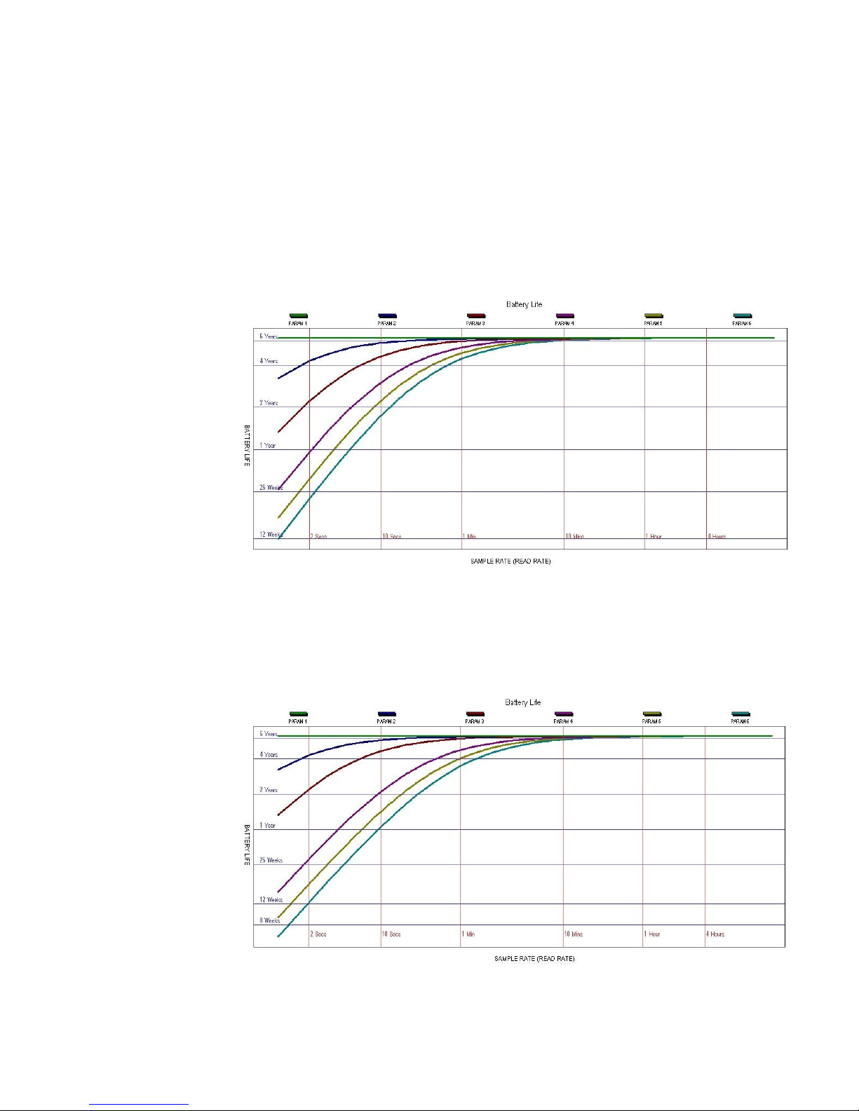
1.8 Battery Life
Battery life depends upon a number of factors: how many channels are enabled, the read rate, the ambient
temperature, the display update rate etc. The following graph assumes:
• Display update rate >= 20 seconds,
• 10°C < Ambient temperature < 40 °C
• 2200mAh battery fitted.
1.8.1
Tips for extending battery life:
1 Do not enable more channels that you actually need
2 Select the longest practical read rate. The default read rate is 30 seconds
3 Increase display update rate. The default display update rate is 10 seconds
1.8.2
Battery Life for Internal Temperature Only, Internal Humidity and Frequency
PARAM 1 = NAP MODE (Data Logger not logging) (Power save mode)
PARAM 2 = Internal Temperature Only and/or Frequency Channel
PARAM 3 = Internal Humidity Channel and/or Frequency Channel.
SL7000 User Guide
Drawing No: SIG-1135-01-17 Page 6 of 30
Change Note: CN0054
1.8.3
Battery Life including 1 universal channel enabled
PARAM 1 = NAP MODE (Data Logger not logging) (Power save mode)
PARAM 2 = Internal Temperature Only and/or Frequency Channel
PARAM 3 = Internal Humidity Channel and/or Frequency Channel.
PARAM 4 = Internal Temperature and one universal channel (set as Thermocouple/±100mV/0 to 1V/ 0 to 10V/4 to
20mA)
PARAM 5 = Internal Temperature and one universal channel (set a Slidewire or Thermistor)
PARAM 6 = Internal Temperature and one universal channel (set a RTD LO or RTD HI)
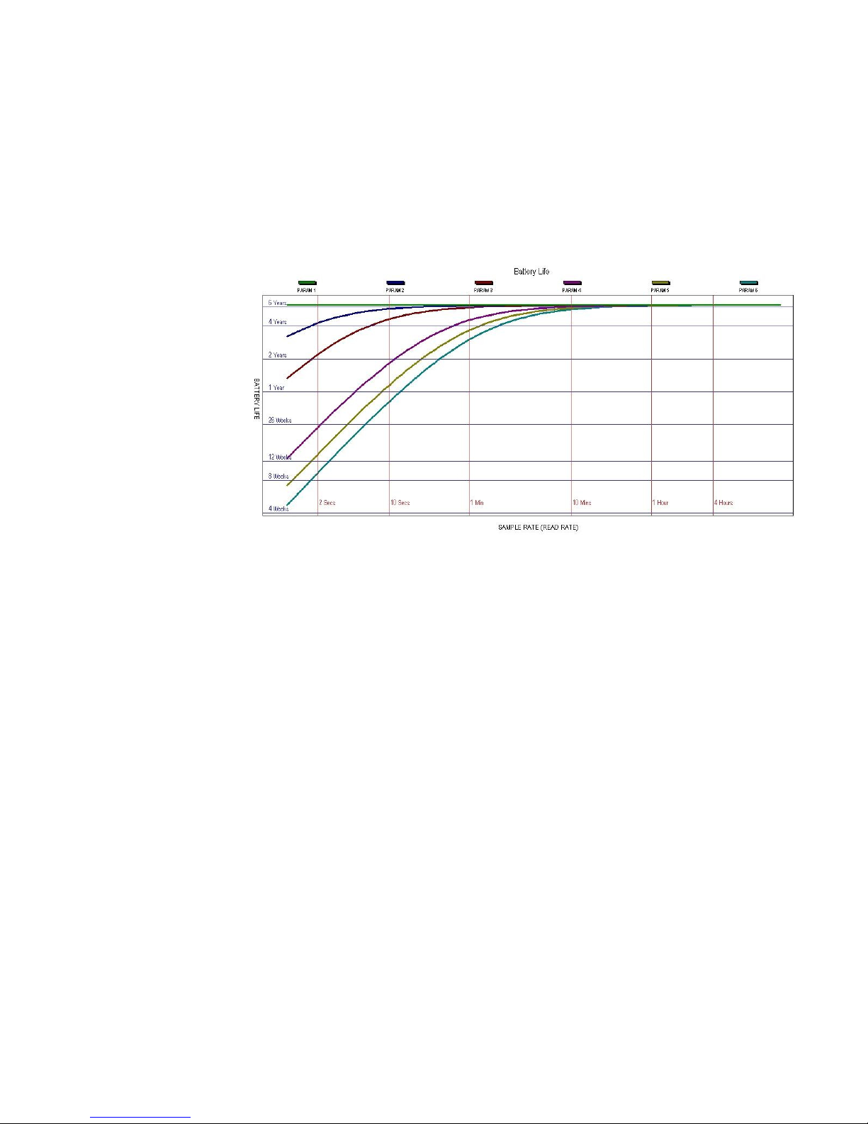
1.8.4
Battery Life including 2 universal channel enabled
PARAM 1 = NAP MODE (Data Logger not logging) (Power save mode)
PARAM 2 = Internal Temperature Only and/or Frequency Channel
PARAM 3 = Internal Humidity Channel and/or Frequency Channel.
PARAM 4 = Internal Temperature and two universal channels (all set as Thermocouple/±100mV/0 to 1V/ 0 to 10V/4 to
20mA)
PARAM 5 = Internal Temperature and two universal channels (all set a Slidewire or Thermistor)
PARAM 6 = Internal Temperature and two universal channels (all set a RTD LO or RTD HI)
SL7000 User Guide
Drawing No: SIG-1135-01-17 Page 7 of 30
Change Note: CN0054
1.8.5
Battery Life including 4 universal channel enabled
PARAM 1 = NAP MODE (Data Logger not logging) (Power save mode)
PARAM 2 = Internal Temperature Only and/or Frequency Channel
PARAM 3 = Internal Humidity Channel and/or Frequency Channel.
PARAM 4 = Internal Temperature and four universal channels (all set as Thermocouple/±100mV/0 to 1V/ 0 to 10V/4 to
20mA)
PARAM 5 = Internal Temperature and four universal channels (all set a Slidewire or Thermistor)
PARAM 6 = Internal Temperature and four universal channels (all set a RTD LO or RTD HI)
SL7000 User Guide
Drawing No: SIG-1135-01-17 Page 8 of 30
Change Note: CN0054
1.9 Recalibration
The SL7000 logger is supplied will all ranges pre-calibrated and should not require any further re-calibration for a
period of 12 months. It is possible to set a calibration reminder within the TempIT software at a selectable period,
which we recommend to be no more than 12 monthly intervals. It is not possible for the user to perform a full
calibration and the unit should be returned to the supplier. Signatrol offer a re-calibration service traceable to
national standards.
The user can, however enter individual span and offset corrections for each channel ( See 10.8). This option is
password protected to prevent un-authorised access.
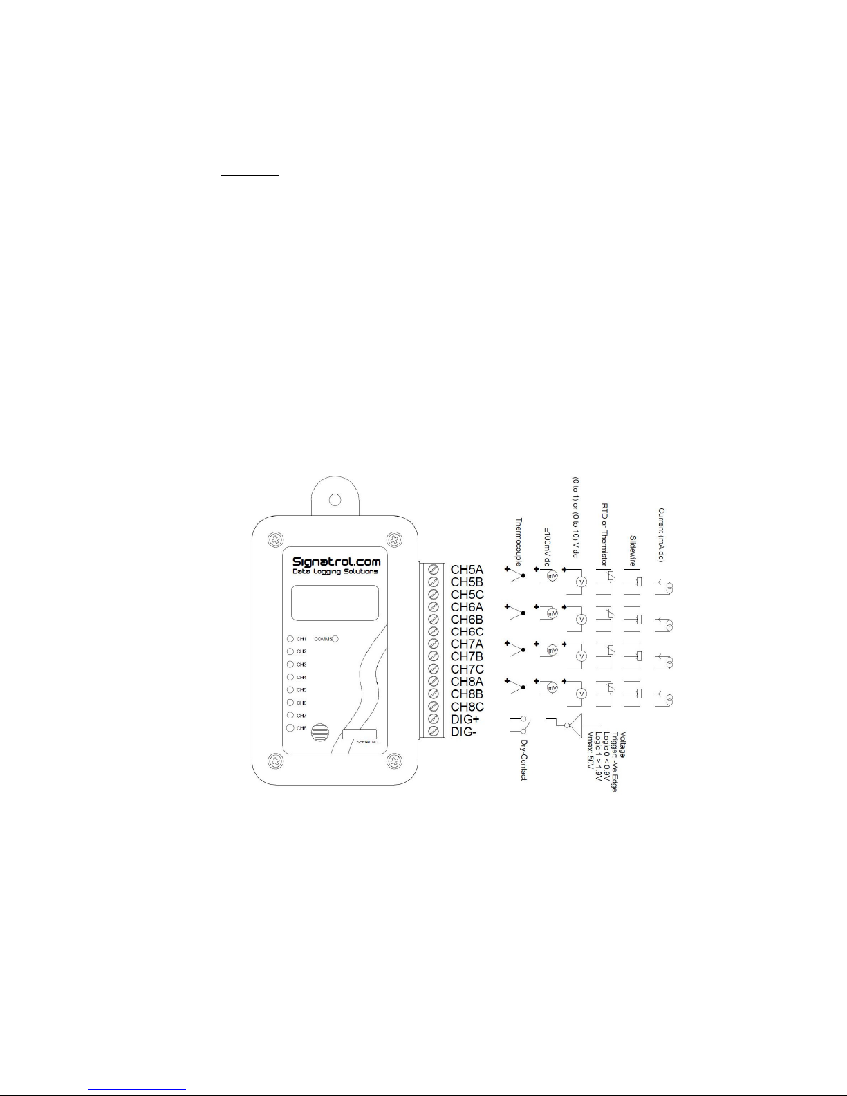
2 Sensor Connections
The following sensor types are accommodated as follows:
Voltage
Current
Thermocouple (isolated tip)
RTD (Lo and Hi)
Slidewire
Thermistor
External Temp/RH probe
Sensors are connected as follows:
Note: Thermocouple / RTD and Thermistor sensors should be isolated types.
They should also be insulation tested at 500Vdc to check the insulation resistance is > 100Mohms.
Having selected the correct sensor type the appropriate connections can be made. The type of sensor used must
be selected via the software prior to issue.
Note: The inputs are isolated from the communications port but not from each other. Care should be taken to avoid
ground loop problems. All thermocouple probes should be of the isolated junction type.

SL7000 User Guide
Drawing No: SIG-1135-01-17 Page 9 of 30
Change Note: CN0054
3 External Power Supply
In order to provide extended battery life, especially at fast scan rates, it is possible to fit an external battery or
battery eliminator. This simply plugs into the socket on the base of the unit.
An appropriate power supply is available from your supplier.
Warning: Only use low earth leakage power supplies, with a leakage of 10micro Amps or less.
4 External Temperature/RH sensor
The SL7000 can accept an external temperature and RH sensor which is simply plugged into the socket on the
base of the unit.
It is currently not possible to have both the external Temperature RH sensor and the external power supply as they
share the same connector, although you could wire both into a single connector. Should you wish to de this please
contact our service department for details.
5 Installing TempIT software
Warning: Ensure that the software has been installed BEFORE Connecting the logger or the Pro-Dongle (when
used) to the PC.
To install the software, ensure that no applications are currently running and insert the CD provided and select the
‘Install Software’ option from the menu. When the install is completed we recommend that the machine is restarted.
A new Icon will have been placed on the desk top.
Note. The drivers should now have been installed automatically. After installing the software, connect the logger
and the Dongle (where used) to the appropriate USB ports. Windows will now attempt to identify the devices. If
Windows cannot find the appropriate drivers it will prompt you to supply the location . The default location is
c:\program files\TempIT4\DRIVERS\.
If the device is connected before the driver has been installed it will install as an ‘unknown device’. This
must then be removed in order to perform a correct installation.
 Loading...