

Signatrol Professional weather station Operation Manual

www.signatrol.com
PROFESSIONAL WEATHER STATION
(WIND AND AIR PRESSURE)
Operation Manual
About this manual
Thank you and congratulations on selecting this professional weather station! We
are positive you will enjoy the benefits of accurate weather readings and the
precise radio controlled time information that our instruments offer.
This manual will guide you step-by-step through setting up your device. Use this
manual to become familiar with your professional weather station, and save it for
future reference.
Glossary of Common Terms
DCF/WWVB/MSF
The DCF, WWVB or MSF time signal is an AM modulated time-of-day signal
broadcasted by the Federal Government of Germany, NIST from USA or National
Physical Laboratory. The time base is generated from an atomic time generator
which is accurate to 10 billions of one second.
LCD
“LCD” is an acronym for ”Liquid Crystal Display”. This is a common type of
display screen used in televisions, computers, watches, and digital clocks.
BAROMETER & BAROMETRIC PRESSURE
A barometer is a device that measures the pressure of the air pushing on it—this
measurement is called the barometric pressure. We don’t actually feel the
barometric pressure because the air pressure is pushing equally in every direction.
RELATIVE AIR PRESSURE
Relative air pressure is the same as the barometric pressure. The calculation of
relative air pressure is a combination of the absolute air pressure and the altitude.
ABSOLUTE AIR PRESSURE
Absolute air pressure is the actual air pressure on the barometer without regard to
altitude.
INCHES OF MERCURY (inHg)
Inches of Mercury is the common unit of measurement for air pressure in the
- 1 -
www.signatrol.com
www.signatrol.com
Signatrol Ltd, UK
Tel: +44 (0)1684 299399
www.signatrol.com
United States.
HECTOPASCALS (hPa)
Hectopascals are the common units of measurement for air pressure in the
International System (SI) of measurement. The hectopascal holds the same
value
Important Note:
The Professional weather station includes a base station (receiver), a transmitter
unit, one wind direction sensor, one wind speed sensor, one rain gauge, USB
cable and a PC software package on CD-ROM.
An added feature of the Weather Station is the readout of all measured and
displayed time and weather data on a PC.
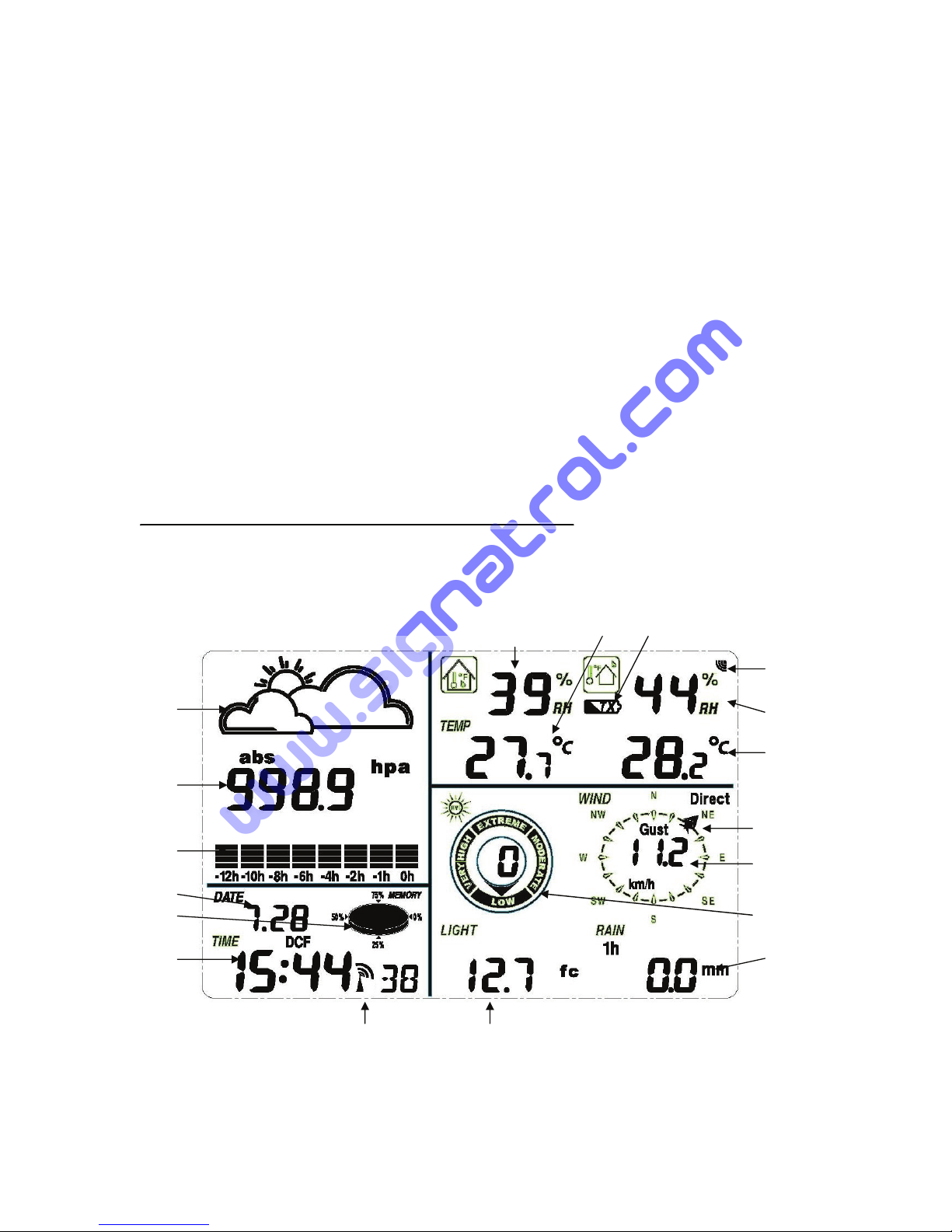
LCD display
- 2 -
7. 8. 9
10
1. 11.
12.
2.
13.
3.
14
4.
5. 15.
6. 16.
18 17.
www.signatrol.com
www.signatrol.com
Signatrol Ltd, UK
Tel: +44 (0)1684 299399
www.signatrol.com
1. Weather Forecast
2. Barometric Pressure
3. Barometric trend
4. Date
5. Memory
6. Time
7. Indoor Humidity
8. Indoor Temperature
9. transmitter low battery indicator
10. Outdoor reception signal
11. Outdoor Humidity
12. Outdoor Temperature
13. Wind direction
14. Wind speed/Gust
15. UV index
16. Rainfall
17. Light
18. Radio Controlled Clock (RCC)
Note: The presence of the "Alarm-On icon" in the section means that the particular
alarm has been enabled.
Set up Guide
Before placing and installing all components of the weather station at there final
destination, please set up the weather station with all parts being nearby for testing
the correct function.
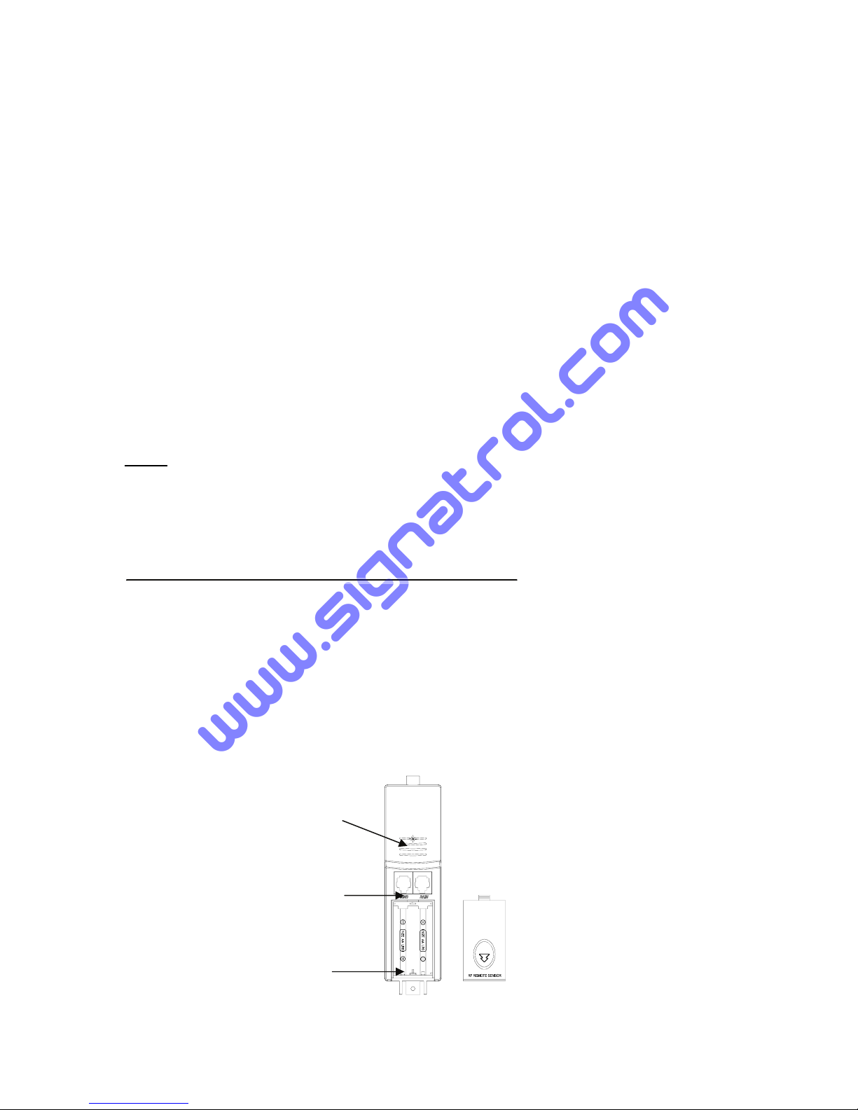
Setting up the base station and transmitter
LED Indicator
Sensor Sockets
Battery
Compartment
Battery cover
Thermo-hygro Sensor
Setting up using batteries:
- 3 -
www.signatrol.com
www.signatrol.com
Signatrol Ltd, UK
Tel: +44 (0)1684 299399

www.signatrol.com
1) Insert 2XAA 1,5V alkaline rechargeable batteries first into the battery
compartment of the remote sensor and immediately afterwards 3XAA 1,5V
alkaline batteries in the base station, observing the correct polarity. When
battery is first inserted, the red LED light on the remote sensor will be light up
for 3-4 seconds. (If no LED light up or is lighted permanently, make sure the
battery is inserted the correct way or a proper reset is happened)
2) When the base station is powered up, the LCD display activates for 3 seconds
and after the “Beep”, it begins measuring indoor temperature, humidity and air
pressure. The unit then enter the RF(Radio Frequency) state, where it receives
data from the remote sensor and RCC(Radio Controlled Clock) receiving state
at the same time. During radio controlled time reception period, there is no
transmission and normal transmission will only resume after time reception
routine is complete. The longest time for radio controlled time reception is 5
minutes.
RF (Radio Frequency) Receiving Mode
1. After power-on, the weather station enters RF receiving state for 144s.
2. Base station receive the temperature, humidity, wind speed and rain data each
48s, receive illuminance date each 60s. If there is no new effective signal from
the sensor in constance receiption failure 8 times, the outdoor temperature and
humidity will display “----”. The base station will start search the new remote sensor
signal for 144s.
3. Hold the “▼” key for 4s to enter manual RF receiving state.
4. Do not press any key before outdoor sensor data received, otherwise the
outdoor sensor learning mode will be terminated. When outdoor transmitter has
been registered, the base station will automatically switch to the normal display
mode from which all further settings can be performed by the user.
5. If there is no temperature reading in the indoor station, make sure the units are
within range of each other or repeat the battery installation procedure.
RCC (Radio Controlled Clock) Receiving Mode
1. After the thermo-hygro sensor is powered up, the sensor will transmit weather
data for 24s, and then the sensor will start radio controlled time reception. During
the RCC time reception period (maximum 5 minutes), no weather data will be
transmitted.
2.If no RCC signal is detected in the initial setup, the thermo-hygro sensor will try
once every hour to get an RCC signal until a signal is received. Once the sensor
receives the RCC signal it will transmit the signal to the base station, the received
time and date will overwrite the manually set time and date, on the base station the
RCC icon will be displayed. If the base station doesn’t receive the RCC signal or
loses the signal the RCC icon will not be display.
3. If your time zone is not at UTC+1:00, then manually set the time zone so
that your clock time will be updated correctly after radio controlled time is
received.
- 4 -
www.signatrol.com
www.signatrol.com
Signatrol Ltd, UK
Tel: +44 (0)1684 299399
www.signatrol.com
4. The best condition for reception is at night, between midnight and 6:00am –
when there is less atmospheric interference.
Note:
Commonly the radio communication between receiver and transmitter in the open
field can reach a distance of up to 330 feet providing that there are no interfering
obstacles such as buildings, trees, vehicles, high voltage lines, etc.
Radio interferences such as PC screens, radios or TV sets can, in bad cases,
entirely cut off radio communication. Please take this into consideration when
choosing standing or mounting locations.
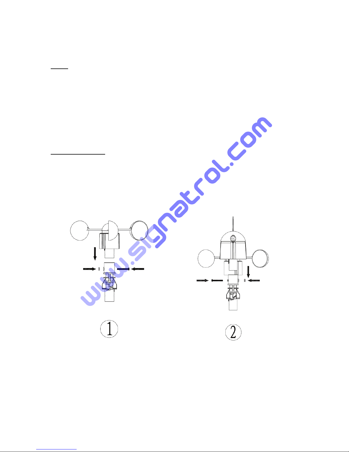
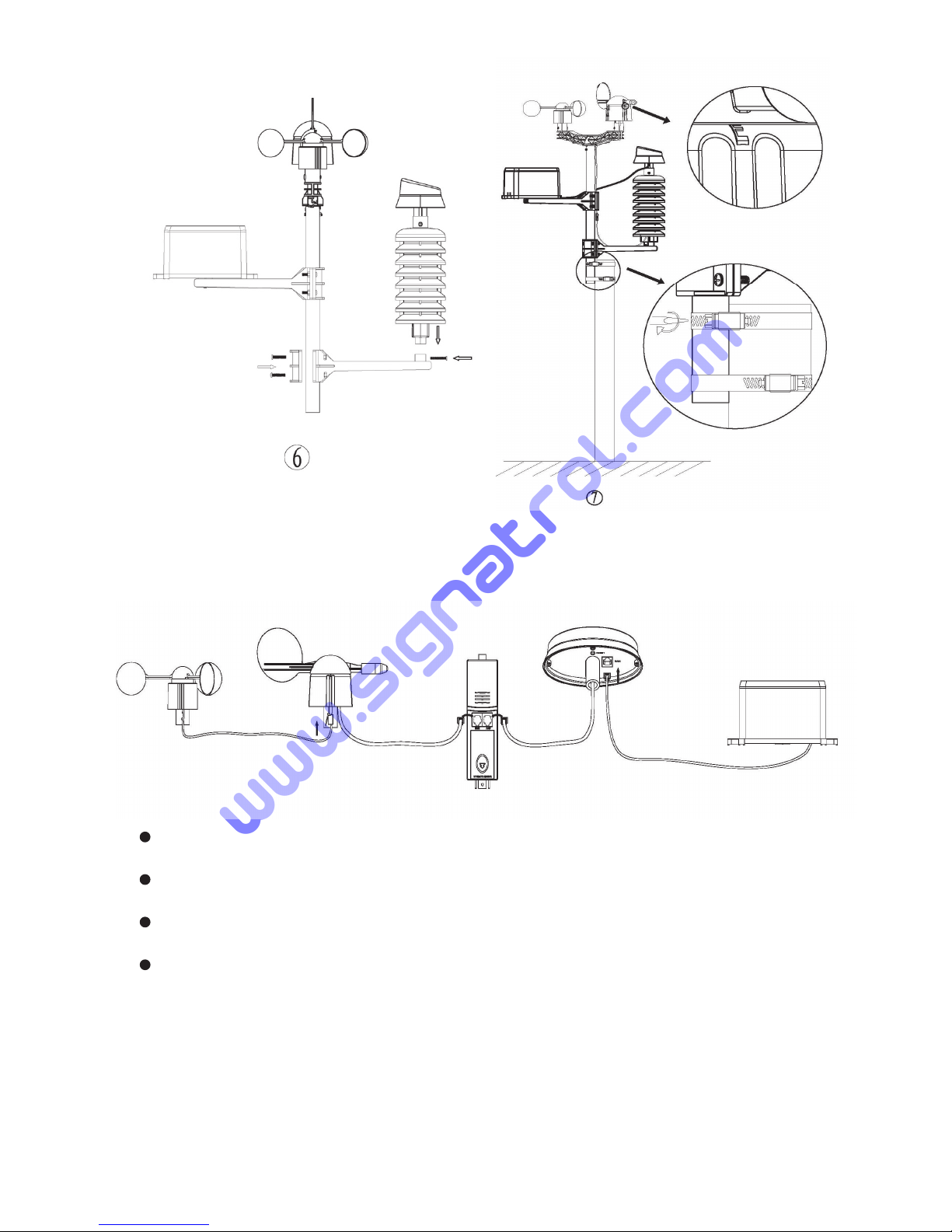
Mounting the sensor
Important Notes:
On the edge of wind direction sensor, there are four alphabet letter of
“N”,”E”,”S”and “W” representing for the direction of North, East, South and West.
Wind direction sensor has to be adjusted so that the directions on the sensor are
matching with your real location. Permanent wind direction error will be introduced
when the wind direction sensor is not positioned correctly during installation.
Anemometer wind direction sensor
- 5 -
www.signatrol.com
www.signatrol.com
Signatrol Ltd, UK
Tel: +44 (0)1684 299399
www.signatrol.com
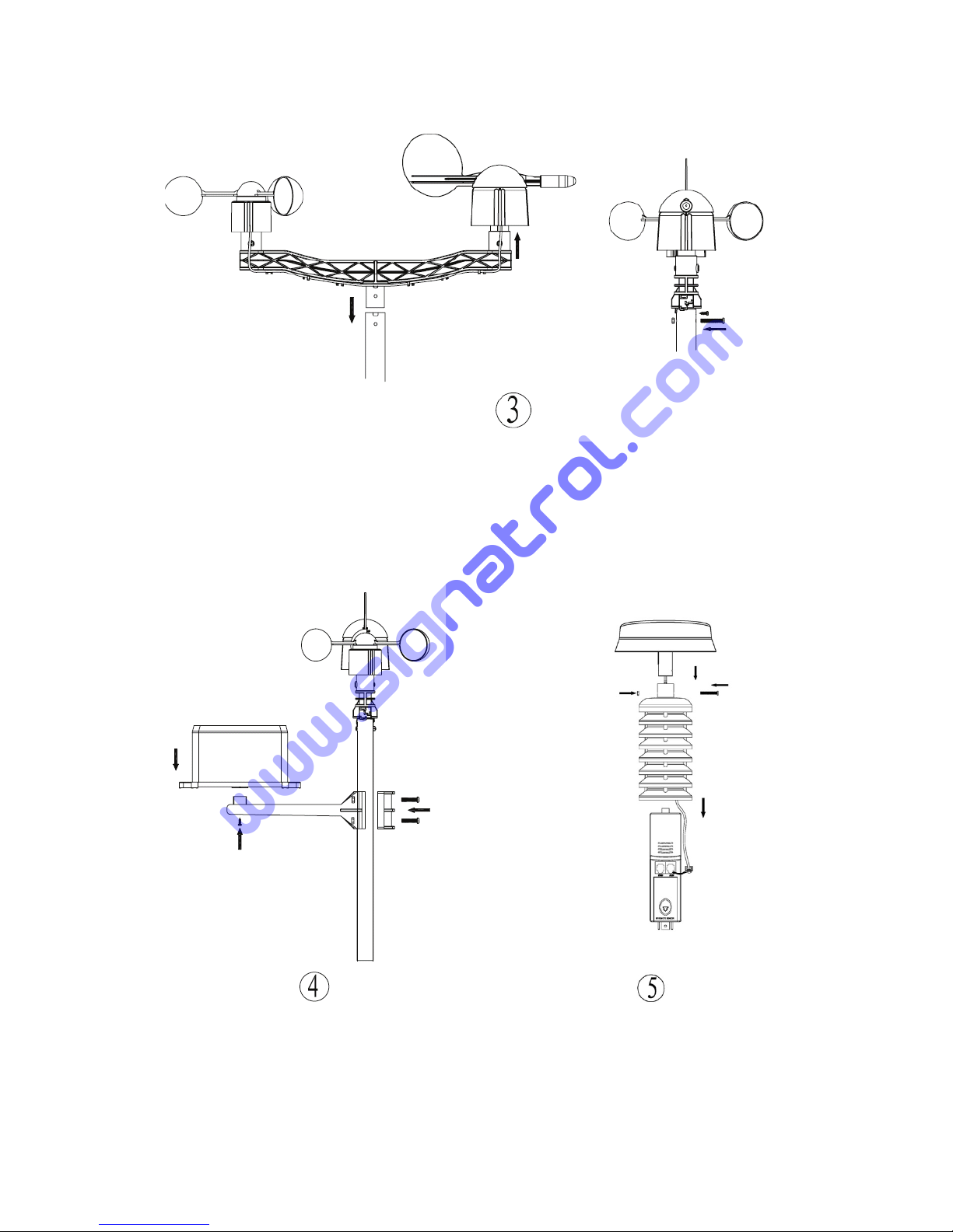
Mounting the dual wind sensor holder
Mounting the rain sensor Thermo-hygro sensor with solar panel
- 6 -
www.signatrol.com
www.signatrol.com
Signatrol Ltd, UK
Tel: +44 (0)1684 299399
www.signatrol.com
Mounting the thermo-hygro sensor Fix the whole set to a pole
same as rain sensor with the two adjustable hoops.
The anemometer’s cable is connected to the input on the wind direction
sensor.
The wind direction sensor’s cable is connected to the input marked Wind on
the thermo-hygro sensor
The rain sensor’s cable is connected to the input marked Rain on the solar
panel
The solar panel’s cable is connected to the input marked Rain on the
thermo-hygro sensor.
The solar transmitter
The solar transmitter makes use of solar energy to power the instruments they are
connected to.
Note: It use AA size alkaline rechargeable batteries. For the solar transmitters to
function properly, make sure the solar receptors on the transmitters are exposed to
sunlight and the connectors of the connection cable are securely plugged in.
- 7 -
www.signatrol.com
www.signatrol.com
Signatrol Ltd, UK
Tel: +44 (0)1684 299399
www.signatrol.com
For best results, direct solar panel as follows:
Solar panel facing north if you reside in the southern hemisphere; Solar panel
facing south if you reside in the northern hemisphere.
Positioning
Once you have verified that all of the components of the weather station are
working, they can be positioned in their permanent places. Before permanently
mounting, make sure that all components work properly together at their chosen
mounting or standing locations. If e.g. there appear to be problems with the 433
MHz radio transmission, they can mostly be overcome by moving the mounting
locations.
Program Mode
The base station has six keys for easy operation: MENU key, ▲(UP) key, ▼
(DOWN) key, ENTER key, HISTORY key, ON/OFF key
Note: Because of the default settings already determined by the manufacturer it
may not necessary for the majority of user to perform-except the relative
pressure(see further down)-any further basic settings and changes, however, can
be easily made.
Note: Keeping the ▲(UP) or ▼(DOWN) key depressed when setting certain
units in the manual setting mode will increase/decrease digits in greater steps.
The setting procedure can be exited at any time by either pressing the HISTORY
key or waiting for the 30-second time-out to take effect.
The basic settings can now be performed in the following order:
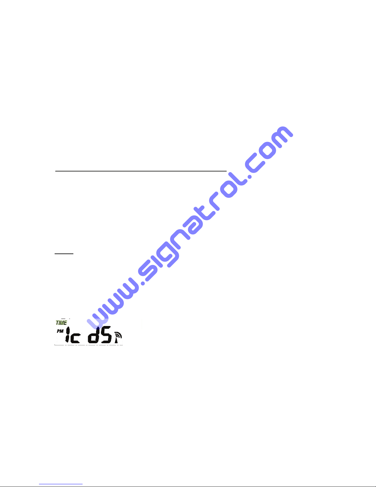
Time
- Press the MENU key to select the TIME section, TIME section digits will start
flashing. Enter LCD contrast setting mode (level 0-8, default level 5), press the
▲(UP) or ▼(DOWN) key to set the value.
- Press the ENTER key to select the following modes:
z Time zone
Note: At Europe, 0 for GMT+1 time zone, 1 for GMT+2 time zone, -1 for GMT
time zone.
At America, -4 for Atlantic time zone, -5 for Eastern Time zone, -6 for
Central Time Zone, -7 for Mountain Time zone, -8 for Pacific time zone,
-9 for Alaska time zone, -10 for Hawaii time zone.
- 8 -
www.signatrol.com
www.signatrol.com
Signatrol Ltd, UK
Tel: +44 (0)1684 299399
www.signatrol.com
z 12/24h time display select (default 12 hours)
z DST ON/OFF (this function is only available for WWVB version, while for DCF
version this feature is not activated)
z Manual time setting (hours/minutes)
Press the ▲(UP) or ▼(DOWN) key to set the value.
Note: Press ON/OFF key to set the DST ON/OFF. “DST OFF” indicates that the
feature is off and the internal real time clock will not change times automatically.
“DST ON” indicates that the feature is on and the internal real time clock will
change times according to the DST time schedule automatically. Some locations
(Arizona and parts of Indiana) do not follow Daylight Saving Time, and should
select “DST OFF”.
Date
- Press the MENU key twice to select the DATE section, DATE section digits will
start flashing. Enter DD-MM-SECOND/DD-MM-WEEK/Time alarm display mode.
(Default DD-MM-SECOND format), press the ▲(UP) or ▼(DOWN) key to select
the display mode.
- Press the ENTER key to select the following modes, press the ▲(UP) or ▼
(DOWN) key to set the value:
z Select DD-MM or MM-DD format. (Default DD-MM format)
z Calendar setting (year/month/date)
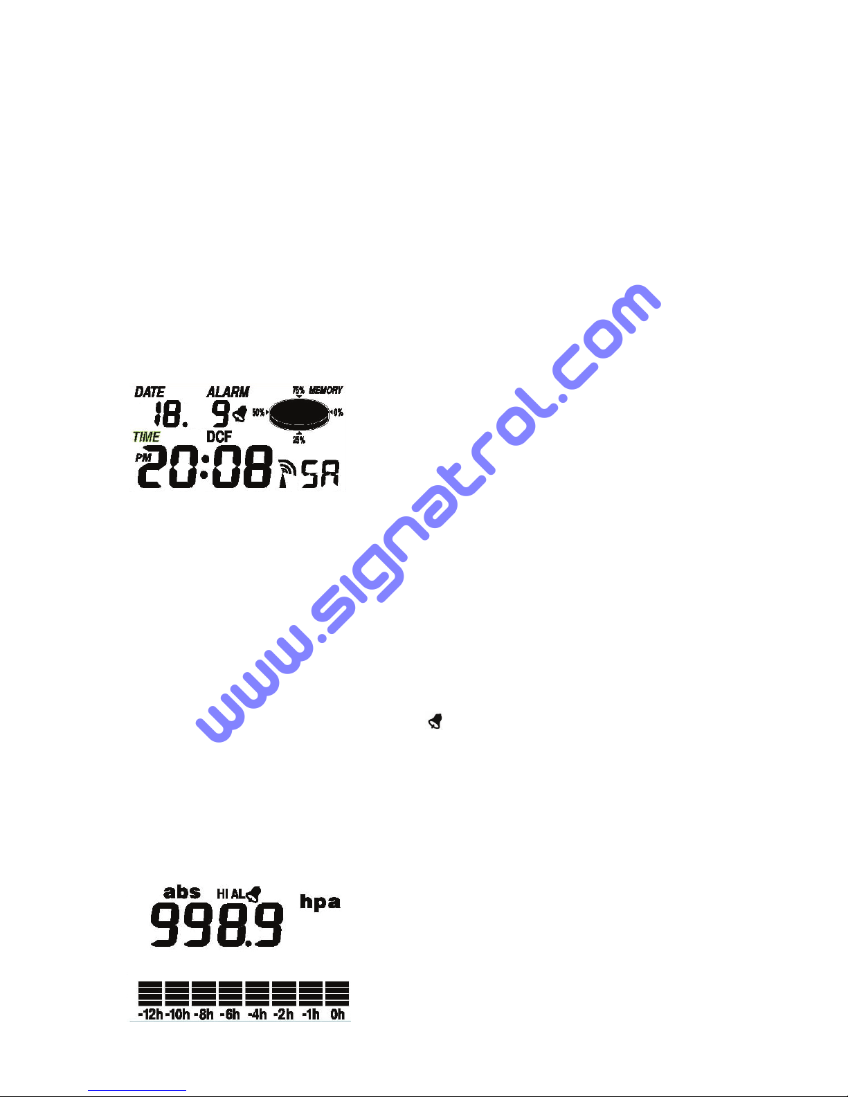
z Time alarm setting. (Hours/minutes). Press the ON/OFF key to on/off the alarm.
If alarm is enabled, an alarm symbol
appears in the display indicating the
alarm function has been enabled.
Note: When a set weather alarm condition has been triggered that particular alarm
will sound for 120 seconds. The corresponding value, ‘HI AL” or “LO AL” and the
alarm symbol are flashing until the weather condition doesn’t meet the user set
level. Press any key to mute the alarm.
Pressure history bar graph
- 9 -
www.signatrol.com
www.signatrol.com
Signatrol Ltd, UK
Tel: +44 (0)1684 299399
 Loading...