

Signametrics Corporation SMU2055 Operator's Manual
Operator's Manual
Model SMU2055 6½ Digit USB Digital Multimeter
Signametrics Corporation
April, 2010
Compatible with Rev 1.62 Hardware

CAUTION
In no event shall Signametrics or its Representatives be held liable for any consequential damages whatsoever
(including, without limitation, damages for loss of business profits, business interruption, loss of business
information, or other loss) arising from of the use of or inability to use Signametrics products, even if Signametrics
Corporation has been advised of the possibility of such damages. Because some States do not allow the exclusion or
limitation of liability for consequential damages, the above limitations may not be applicable to you.
2008 Signametrics Corp. Printed in the USA. All rights reserved. Contents of this publication must not be
reproduced in any form without the permission of Signametrics Corporation.
Signametrics 2

TABLE OF CONTENTS
1.0 INTRODUCTION .................................................................................................................................................6
1.1 SAFETY CONSIDERATIONS.......................................................................................................................... 6
1.2 MINIMUM REQUIREMENTS .........................................................................................................................6
1.3 FEATURE SET .............................................................................................................................................6
2.0 SPECIFICATIONS ...............................................................................................................................................7
2.1 DC VOLTAGE MEASUREMENT ...................................................................................................................7
2.2 DC CURRENT MEASUREMENT....................................................................................................................8
2.3 RESISTANCE MEASUREMENTS....................................................................................................................8
2.3.1 2-wire.......................................................................................................................................8
2.3.2 4-wire.......................................................................................................................................8
2.4 AC VOLTAGE MEASUREMENTS..................................................................................................................8
2.4.1 AC Voltage True RMS Measurement.......................................................................................9
2.4.2 AC Volts Accuracy...................................................................................................................9
2.5 AC CURRENT MEASUREMENT, TRUE RMS..............................................................................................10
2.6 DIODE TEST FUNCTION ............................................................................................................................10
2.7 MEASUREMENT RATES CONTROL ............................................................................................................11
2.8 ACCURACY NOTES ...................................................................................................................................11
2.9 OTHER SPECIFICATIONS ...........................................................................................................................12
2.10 ACCESSORIES .........................................................................................................................................13
3.0 GETTING STARTED.........................................................................................................................................14
3.1 SETTING THE DMM..................................................................................................................................14
3.2 INSTALLING THE SOFTWARE.....................................................................................................................14
3.3 INSTALLING THE DMM MODULE .............................................................................................................14
3.4 CALIBRATION FILE ................................................................................................................................... 14
3.5 DMM INPUT TERMINALS .........................................................................................................................15
3.6 DMM REAR PANEL..................................................................................................................................15
3.7 STARTING THE CONTROL PANEL ..............................................................................................................16
3.8 USING THE CONTROL PANEL .................................................................................................................... 16
4.0 DMM OPERATION AND MEASUREMENT TUTORIAL........................................................................... 18
4.1 VOLTAGE MEASUREMENT........................................................................................................................ 18
4.1.1 DC Voltage Measurements ....................................................................................................18
4.1.2 True RMS AC Voltage Measurements ...................................................................................18
4.2 CURRENT MEASUREMENTS ......................................................................................................................18
4.2.1 Improving DC Current Measurements ..................................................................................19
4.3 RESISTANCE MEASUREMENTS..................................................................................................................19
4.3.1 2-Wire Ohm Measurements ...................................................................................................19
4.3.2 4-Wire Ohm Measurements ...................................................................................................19
4.3.3 Effects of Thermo-Voltaic Offset............................................................................................20
4.4 DIODE CHARACTERIZATION .....................................................................................................................20
5.0 WINDOWS INTERFACE..................................................................................................................................21
5.1 DISTRIBUTION FILES ................................................................................................................................21
5.2 USING THE SMU2060 DRIVER SET WITH C++ OR SIMILAR SOFTWARE...................................................22
5.3 VISUAL BASIC FRONT PANEL APPLICATION.............................................................................................23
5.3.1 Visual Basic Simple Application............................................................................................23
5.4 WINDOWS DLL DEFAULT MODES AND PARAMETERS.............................................................................. 24
5.5 USING THE DLL WITH LABWINDOWS/CVI........................................................................................... 24
5.6 WINDOWS COMMAND LANGUAGE ...........................................................................................................24
DMMCalibrate................................................................................................................................25
DMMCleanRelay ............................................................................................................................25
DMMClearMinMax ........................................................................................................................26
3 Signametrics

DMMCloseUSB...............................................................................................................................26
DMMDelay .....................................................................................................................................27
DMMErrString................................................................................................................................27
DMMGetBusInfo.............................................................................................................................28
DMMGetCalDate............................................................................................................................29
DMMGetdB.....................................................................................................................................29
DMMGetdBStr................................................................................................................................30
DMMGetDevLocation.....................................................................................................................30
DMMGetDeviation ......................................................................................................................... 30
DMMGetDeviatStr..........................................................................................................................31
DMMGetDiffMnMxStr....................................................................................................................31
DMMGetFunction...........................................................................................................................32
DMMGetGrdVer.............................................................................................................................32
DMMGetHwVer..............................................................................................................................33
DMMGetHwOption.........................................................................................................................33
DMMGetID.....................................................................................................................................34
DMMGetManDate..........................................................................................................................35
DMMGetMax..................................................................................................................................35
DMMGetMaxStr .............................................................................................................................36
DMMGetMin...................................................................................................................................36
DMMGetMinStr..............................................................................................................................37
DMMGetNumDevices.....................................................................................................................37
DMMGetRange...............................................................................................................................38
DMMGetRate..................................................................................................................................38
DMMGetSupplyV............................................................................................................................39
DMMGetStoredReading .................................................................................................................39
DMMGetType .................................................................................................................................40
DMMGetVer ...................................................................................................................................40
DMMInit .........................................................................................................................................41
DMMIsAutoRange ..........................................................................................................................41
DMMIsInitialized............................................................................................................................42
DMMIsRelative...............................................................................................................................42
DMMOpenUSB...............................................................................................................................43
DMMRead.......................................................................................................................................43
DMMReadNorm..............................................................................................................................44
DMMReadNsamples.......................................................................................................................45
DMMReadStr..................................................................................................................... .............45
DMMSetAutoRange ........................................................................................................................46
DMMSetFunction............................................................................................................................46
DMMSetRange................................................................................................................................47
DMMSetRate...................................................................................................................................48
DMMSetRelative.............................................................................................................................49
DMMTerminate...............................................................................................................................49
5.7 CALIBRATION SERVICE COMMANDS.........................................................................................................49
AC_zero ..........................................................................................................................................50
DMMLoadCalFile...........................................................................................................................50
SetGain............................................................................................................................................51
GetGain...........................................................................................................................................51
GetOffset.........................................................................................................................................52
SetFcomp ........................................................................................................................................53
SetOffset..........................................................................................................................................53
Linearize_AD..................................................................................................................................54
Read_ADcounts ..............................................................................................................................54
5.8 MAINTANANCE COMMANDS.....................................................................................................................55
GrdXingTest ....................................................................................................................................55
WrCalFileToStore...........................................................................................................................55
WrCalStoreToFile...........................................................................................................................56
5.9 ERROR CODES ..........................................................................................................................................57
5.10 WARNING CODES ...................................................................................................................................57
5.11 PARAMETER LIST ...................................................................................................................................58
Signametrics 4

5.11.1 Measurement and Source Functions....................................................................................58
5.11.2 Range Values .......................................................................................................................58
5.11.3 Measurement Rate parameters ............................................................................................59
6 CALIBRATION .....................................................................................................................................................60
7.0 WARRANTY AND SERVICE...........................................................................................................................62
8.0 ACCESSORIES...................................................................................................................................................62
5 Signametrics

1.0 Introduction
Congratulations! You have purchased a USB Digital Multimeter. The SMU2055 Digital Multimeter (DMM) has
sophisticated analog and digital circuitry to provide repeatable measurements, and its protected to handle any
unexpected situations your measurement environment may encounter. Your new DMM is easy to setup and use. To
get years of reliable service from your DMM, please take a few moments to review this manual before installing and
using this precision instrument.
This manual describes the SMU2055 USB module.
1.1 Safety Considerations
Safety Considerations
The SMU2055 DMM is capable of measuring up to 240 VDC or 240 VAC across the Volt HI and LO
terminals, and can also measure common mode signals that "float" the DMM above EARTH ground by up
to 300 VDC or 250 VAC. When making common mode measurements, the majority of the circuits inside
the DMM are set to the common mode voltage. These voltages can be lethal and may KILL!
The DMM comes installed in a plastic chassis with 4 components (bottom, top, front and back) that must
not be removed due to performance as well as safety reasons. Removal of these shields and/or
improper assembly of the shields can expose lethal voltages. The plastic screws are required for safety
reasons.
Warning
Check to see that all measurement wires are separated from the USB communication cable. If
measurement wires come into contact with the USB cable, this may apply measurement voltages to
your computer, causing personal injury and/or damage to your computer!
When making any measurements above 50 VDC or 40 VAC, use only approved Safety Test Leads
such as Signametrics Basic Test Leads or Deluxe Test Leads, offered as optional accessories with the
Signametrics DMM’s.
1.2 Minimum Requirements
The SMU2055 DMMs are precision modules that are compatible with any USB 2.0 or higher computer port. A
mouse must be installed when controlling the DMM from the Windows Control Panel. The SMU2055 comes with
a Windows' DLL, for operation with Windows Version 95/98/Me/2000/XP, Vista and LINUX.
1.3 Feature Set
The SMU2055 is a traditional 6-1/2 digit DMM and can be used as a general purpose DMM. Signametrics also
offers the high precision 7-1/2 digit USB DMM, the SMU2060, which adds capacitance measurements, triggered
operation and a high resolution frequency counter. If your requirements call for a High Workload, then the Multi
Function SMU2064 will probably fit the ticket with its timing measurements, inductance, sourcing and higher
speed. The SMU2064 specialized measurements can replace costly instruments and thus shrinking the size and cost
of a test system.
Signametrics 6
SMU2055 basic features:
Function SMU2055 DMM
Volts DC; four ranges, 240mV to 240V
Volts AC; TRMS; four ranges, 240mV to 240V
2-Wire Ohms, six ranges 240 to 24 M
4-Wire Ohms, six ranges 240 to 24 M
DC current, four ranges 2.4 mA to 2.4 A
AC current, four ranges 2.4 mA to 2.4 A
Diode V/I Five ranges, 100 A to 1mA
Auto range, Relative
Min/Max, dB and percent deviation functions
High Dynamic range; ±2,400,000 counts
Measurement rate selectable: 0.5 to250 readings/s
2.0 Specifications
The following specifications are based on both, verification of large number of units as well as
mathematical evaluation. The specifications should be considered for the specified environment.
It is important to note that a specified range for a DMM is expressed as a numeric value indicating the
highest absolute measurement that can be displayed using that range. The lowest value that can be
detected is expressed by the corresponding resolution for the range.
2.1 DC Voltage Measurement
Input Characteristics
Input Resistance 240 mV, 2.4 V Ranges: >10 G, with typical leakage of 50pA
Input Resistance 24 V, 240 V Ranges: 10.00 M
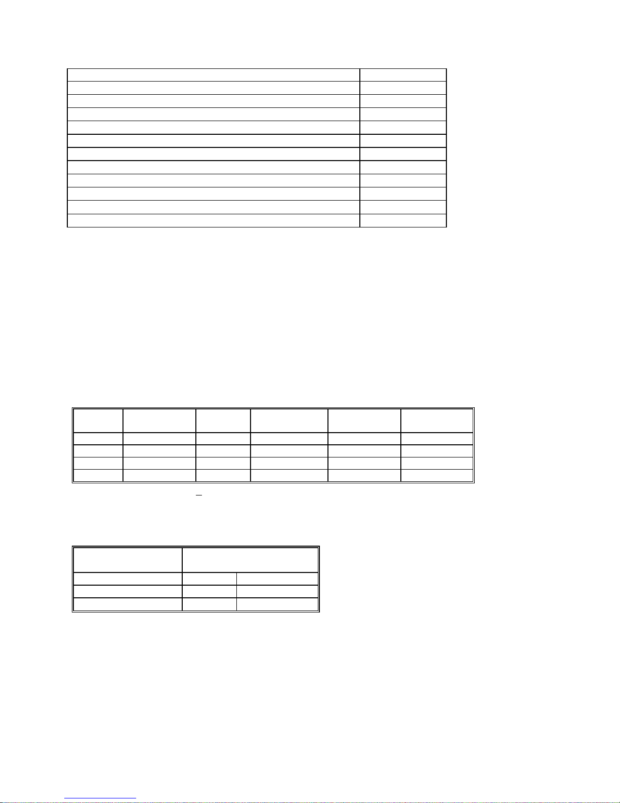
Accuracy ± (% of reading + Volts) [1]
Range Full Scale
6-½ Digits
240 mV 240.0000 mV
2.4 V 2.400000 V
24 V 24.00000 V
240 V 240.0000 V
[1] With reading rate set to < 2/sec, and within one hour from Self Calibration (S-Cal).
For resolution at higher measurement rates, see the following table. Use this table for DC Volts, DC
Current and Resistance measurements.
Maximum reading rate
1 / second 6-1/2 22 bits
27/second 6 20 bits
250 / second 5-1/2 18 bits
DCV Noise Rejection Normal Mode Rejection, at 50, 60, or 400 Hz ± 0.5%, is better than 95 dB
for Rates of 6rps and lower. Common Mode Rejection (with 1 k lead imbalance) is better than 120
dB for these conditions.
Resolution 24 hours
23C 1C
100 V 0.003 + 2 V 0.005 + 3 V 0.007 + 3.5 V
1 V 0.003 + 3 V 0.004 + 4 V 0.005 + 10 V
10 V 0.004 + 200 V 0.005 + 250 V 0.007 + 300 V
100 V
0.004 + 600 V 0.005 + 800 V
Digits of Resolution
90 Days
23C 5C
One Year 23C
5C
0.007 + 1 mV
7 Signametrics
2.2 DC Current Measurement
Input Characteristics
Number of built-in shunts Two
Currents greater than 2.4A require external shunt
Protected with 2.5A Fast blow fuse
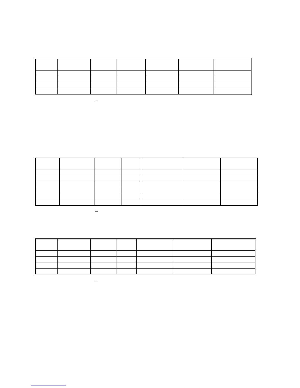
Accuracy ± (% of reading + Amps) [1]
Range Full Scale
Reading
2.4 mA 2.40000 mA
24 mA 24.0000 mA
240 mA 240.000 mA
2.4 A 2.40000 A
Resolution Max Burden
Voltage
10 A
100 A
1 A
10 A
25mV
250mV
55mV
520mV
24 hours
23C 5C
0.05 + 300 A 0.06 + 700 A 0.07 + 1 A
0.05 + 350 A 0.065 + 800 A 0.08 + 1 A
0.05 + 50 A 0.055 + 60 A 0.065 + 80 A
0.3 + 60 A 0.4 + 70 A 0.45 + 90 A
90 Days
23C 5C
One Year 23C
5C
[1] With reading rate set to < 2/sec, and within one hour from Zero (Relative control).
2.3 Resistance Measurements
Characteristics
Number of current sources Five
Maximum Test Voltage 2.4V
2.3.1 2-wire
Accuracy ± (% of reading + ) [1]
Range Full Scale
6 ½ Digits
240 240.0000 100
2.4 k 2.400000 k 1 m
24 k 24.00000 k 10 m 100 A 0.003 + 300 m 0.004 + 330 m 0.007 + 350 m
240 k 240.0000 k 100 m 10 A 0.008 + 3.2 0.012 + 4 0.02 + 5
2.4 M 2.400000 M 1 1 A 0.02 + 40 0.03 + 50 0.04 + 70
24 M 24.0000 M 100
Resolution Source
current
1 mA
1 mA
100 nA
24 hours
23C 1C
0.004 + 4.5 m [2] 0.005 + 5 m [2] 0.008 + 6 m [2]
0.0025 + 28 m 0.004 + 32 m 0.007 + 33 m
0.2 + 400 0. 3 + 500 0.4 + 600
90 Days
23C 5C
One Year
23C 5C
[1] With reading rate set to < 2/sec, and within one hour from Self Calibration (S-Cal).
[2] Use of S-Cal and Relative to improve measurement floor.
2.3.2 4-wire
Accuracy ± (% of reading + ) [1]
Range
[3]
240 240.0000 100
2.4 k 2.400000 k 1 m
24 k 24.00000 k 10 m 100 A 0.003 + 300 m 0.004 + 330 m 0.007 + 350 m
240 k 240.0000 k 100 m 10 A 0.008 + 3.2 0.012 + 4 0.02 + 5
[1] With reading rate set to < 2/sec, and within one hour from Self Calibration (S-Cal).
[2] Use of Relative to facilitate indicated floor.
[3] The 2.4MΩ and 24MΩ ranges are functional but not specified for 4-Wire operations.
Full Scale
6 ½ Digits
Resolution Source
current
1 mA
1 mA
24 hours
23C 1C
0.004 + 3 m [2] 0.005 + 4 m [2] 0.008 + 5 m [2]
0.0025 + 28 m 0.004+ 32 m 0.007 + 33 m
90 Days
23C 5C
One Year
23C 5C
2.4 AC Voltage Measurements
Input Characteristics
Input Resistance 1 M, shunted by < 300 pF
Max. Crest Factor 4 at Full Scale, increasing to 7 at Lowest Specified Voltage
AC coupled Specified range: 10 Hz to 200 kHz
Typical Settling time < 0.5 sec to within 0.1% of final value
Common Mode rejection: at 50Hz to 60Hz, 1 k imbalance in either lead, is better than 60 dB.
Signametrics 8
2.4.1 AC Voltage True RMS Measurement
Range [1] Full Scale 6-½ Digits Lowest specified Voltage Resolution
240 mV 240.0000 mV 5 mV
2.4 V 2.400000 V 20 mV
24 V 24.00000 V 200 mV
240 V 240.0000 V 2 V
[1] Signal is limited to 8x10⁶ Volt Hz Product. For example, the largest frequency input at 250 V is 32
kHz, or 8x10
6
Volt x Hz.
100 V
1 V
10 V
100 V
2.4.2 AC Volts Accuracy
Settles to rated accuracy within 0.5 seconds for signals >50% of scale.
May take up to 2s to settle to rated accuracy for signals < 5% of scale.
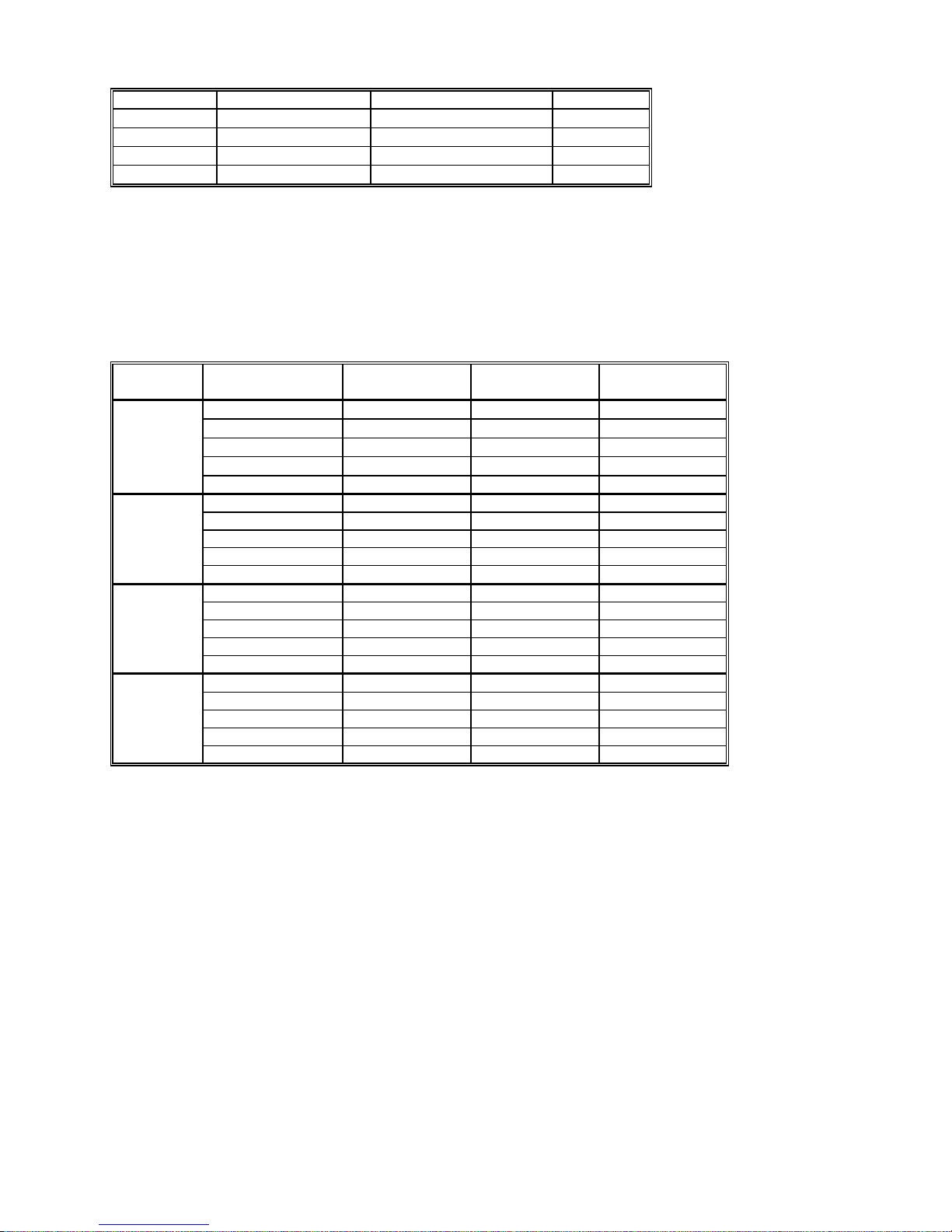
Accuracy ± (% of reading + Volts) [1]
Range Frequency 24 hours
23C 1C
240 mV
2.4 V
24 V
240 V
10 Hz - 20 Hz
20 Hz - 47 Hz
47 Hz – 10 kHz
10 kHz – 50 kHz
50 kHz - 100 kHz 2 + 0.6 mV 2.1 + 0.8 mV 2.2+ 1 mV
10 Hz - 20 Hz 3 + 2 mV 3.3 + 2.2 mV 3.5 + 2.5 mV
20 Hz - 47 Hz 0.45 + 1.3 mV 0.47 + 1.5 mV 0.5 + 1.7 mV
47 Hz – 10 kHz 0.07 + 1 mV 0.075 + 1.1 mV 0.08 + 1.2 mV
10 kHz – 50 kHz 0.35 + 2 mV 0.37 + 2.3 mV 0.4 + 2.5 mV
50 kHz - 100 kHz 2+ 2.5 mV 2.1 + 2.8 mV 2.2 + 5 mV
10 Hz - 20 Hz 4 + 25 mV 4.3 + 16 mV 4.5 + 35 mV
20 Hz - 47 Hz 0.50 + 20 mV 0.55 + 25 mV 0.65 + 30 mV
47 Hz – 10 kHz 0.07 + 15 mV 0.075 + 20 mV 0.085 + 23 mV
10 kHz – 50 kHz 0.2 + 25 mV 0.25 + 30 mV 0.3 + 35 mV
50 kHz - 100 kHz 1.5 + 35 mV 1.6 + 28 mV 1.7 + 50 mV
10 Hz - 20 Hz 3 + 250 mV 3.1 + 350 mV 3.3 + 400 mV
20 Hz - 47 Hz 0.45 + 230 mV 0.+ 300 mV 0.+ 350 mV
47 Hz – 10 kHz 0.07 + 180 mV 0.075 + 220 mV 0.08 + 250 mV
10 kHz – 50 kHz 0.28 + 250 mV 0.29 + 300 mV 0.55 + 350 mV
50 kHz - 100 kHz 1.5 + 350 mV 1.6 + 400 mV 1.8 + 500 mV
3 + 300 V 3.4 + 500 V
0.45 + 150 V 0.47 + 170 V
0.13 + 100 V 0.14 + 110 V
0.3 + 180 V 0.35 + 220 V
[1] With reading rate set to ≤ 2/sec
ACV Noise Rejection Common Mode rejection, for 50 Hz or 60 Hz with 1 k imbalance in either lead, is better
than 60 dB.
Specs in red indicate change from last manual release.
90 Days
23C 5C
One Year
23C 5C
3.6 + 0.6 mV
0.5 + 0.35 mV
0.16 + 0.25 mV
0.4 + 0.35 mV
9 Signametrics

2.5 AC Current Measurement, True RMS
Input Characteristics
Crest Factor 4 at Full Scale
Number of built-in shunts Two
Currents greater than 2.4A require external shunt
Protected with 2.5A Fast blow fuse
2.5.1 AC Current True RMS Measurement
Range Full Scale 6 1/2 Digits Lowest Specified
Current
2.4 mA 2.400000 mA
24 mA 24.00000 mA
240 mA 240.0000 mA 3 mA 55mV 100 nA
2.4 A 2.400000 A 30 mA 520mV 1 uA
60 A
300 A
Accuracy ± (% of reading + Amps)
Range Frequency [1] 24 hours
23C 1C
2.4 mA
24 mA
240 mA
2.4 A
10 Hz - 20 Hz
20 Hz - 47 Hz
47 Hz - 1 kHz
1 kHz - 10 kHz
10 Hz - 20 Hz
20 Hz - 47 Hz
47 Hz - 1 kHz
1 kHz - 10 kHz
10 Hz - 20 Hz
20 Hz - 47 Hz
47 Hz - 1 kHz
1 kHz - 10 kHz
10 Hz - 20 Hz 1.8 + 4 mA 2.5 + 4.5 mA 2.7 + 5 mA
20 Hz - 47 Hz 0.66 + 4 mA 0.8 + 6 mA 0.9 + 6 mA
47 Hz - 1 kHz 0.3 + 3.8mA 0.33 + 3.8 mA 0.35 + 4 mA
1 kHz - 10 kHz 0.4 + 4mA 0.45 + 4.5 mA 0.5 + 5 mA
3.8 + 4 A 2.7 + 4 A 2.9 + 4 A
0.9 + 4 A 0.9 + 4 A 1.0 + 4 A
0.04 + 1.5 A 0.08 + 3 A 0.12 + 4 A
0.12 + 4 A 0.14 + 4 A 0.22 + 4 A
1.8 + 30 A 2.6 + 30 A 2.8 + 30 A
0.6 + 30 A 0.9 + 30 A 1.0 + 30 A
0.07 + 10 A 0.15 + 20 A 0.16 + 30 A
0.21 + 30 A 0.3 + 40 A 0.4 + 40 A
1.8 + 400 A 2.7 + 400 A 2.8 + 400 A
0.6 + 400 A 0.9 + 400 A 1.0 + 400 A
0.1 + 100 A 0.17 + 180 A 0.2 + 220 A
0.3 + 300 A 0.35 + 350 A 0.4 + 400 A
Maximum Burden
Voltage (RMS)
25mV 1 nA
250mV 10 nA
90 Days
23C 10C
One Year
23C 10C
Resolution
2.6 Diode Test Function
Test Currents Five
Current sources voltage compliance 4 V
Accuracy ± (% of reading + Volts) [1]
Range Full Scale
5-½ Digits
0.1 A 0.022 + 15 V
1 A 0.018 + 12 V
10 A 0.015 + 10 V
100 A 0.014 + 8 V
1 mA
2.40000 V
[1] With measurement rate set to 2rps or lower rate
Signametrics 10
Resolution
One Year 23C 10C
10 V
0.014 + 8 V

2.7 Measurement Rates Control
Use DMMSetRate() using the following codes.
Symbol Code
(Readings/sec)
0.5 RATE_p5 0
1 RATE_1 1
2 RATE_2 2
3 RATE_3 3
7 RATE_7 7
14 RATE_14 14
27 RATE_27 27
50 RATE_50 50
90 RATE_90 90
170 RATE_170 170
250 RATE_250 250
Power line Rejection Rate
50Hz 60Hz 400Hz
2.8 Accuracy Notes
Important: all accuracy specifications for DCV, Resistance, DCI, ACV, and ACI apply for the time periods shown
in the respective specification tables. To meet these specifications, Self Calibration must be performed once a day or
as indicated in the specification table. This is a simple software operation that takes a few seconds. It can be
performed by calling Windows command DMMCal(), or selecting S-Cal in the Control Panel.
These products are capable of continuous measurement as well as data transfer rates of up to 250 readings per
second (rps). In general, to achieve 6-1/2 Digits of resolution, the rate should be set to 2rps or lower.
Since the DMM is powered via a USB calbe (AM/BM 6’ cable), it is important to make sure it gets the
required 5V supply. Using the right USB cable is very important. Make sure this cable has a 24 AWG
wires for power supply, indicated by marking on the cable such as 28/1P + 24/2C. Be aware that there are
a lot of cables which are marked 28/1P + 28/2C. These have high resistance, and will not be adequate.
Another issue can be with powered USB hubs. Some of the lower quality units can have upwords of 8V
rather than the required 5V +/-5%. On initialization (DMMInint) the DMM measures its internal supply
voltage and returnes an error or warning code if the power is inadequate. See DMMGetSupplyV function.
11 Signametrics

2.9 Other Specifications
Temperature Coefficient Less than 0.1 x accuracy specification below 18C and over
Hardware Interface Single USB/cPCI 3U slot
Overload Protection (voltage inputs) 250 VDC, 250 VAC
Isolation 300 VDC, 250 VAC from Earth Ground
Maximum Input (Volt x Hertz) 8x10⁶ Volt x Hz normal mode input (across Voltage HI &
1x10⁶ Volt x Hz Common Mode input (from Voltage HI or
Safety Designed to IEC 1010-1, Installation Category II.
Calibration Calibrations are performed by Signametrics in a computer at
Temperature Range Operating -10C to 65C
Temperature Range Storage -40C to 85C
Size Single 3U USB or CompactPCI slot
Power +5 volts, 200 mA maximum
Note: Signametrics reserves the right to make changes in materials, specifications, product functionality, or
accessories without notice.
28C
LO).
LO relative to Earth Ground).
23C internal temperature rise. All calibration constants are
stored in an onboard memory and in a text file.
Signametrics 12

2.10 Accessories
Several accessories are available for the SM2060 series DMMs, which can be purchased directly from Signametrics
Corp, or from one of its approved distributors or representatives. Some of the accessories available:
DMM Probes SM-PRB ($15.70)
6 ft. USB 2.0 AM/BM cable SMU-CBL6ft
3 ft. USB 2.0 AM/BM cable SMU-CBL3ft
10 ft. USB 2.0 AM/BM cable SMU-CBL10ft
DMM Probe kit SM-PRK ($38.50)
Deluxe Probe kit SM-PRD ($95.00).
Shielded SMT Tweezers Probes SM-PRSMT ($24.90).
Multi Stacking Double Banana shielded cable 36” SM-CBL36 ($39.00).
Multi Stacking Double Banana shielded cable 48” SM-CBL48 ($43.00).
Lab View VI’s library SM204x.llb (free).
Linux Driver kit (free).
Extended 3 Year warrantee (calibration not included) $120.00 for SM2055.
13 Signametrics

3.0 Getting Started
After unpacking the DMM, please inspect for any shipping damage that may have occurred, and report
any claims to your transportation carrier.
The package includes the Digital Multimeter; Installation CD, a Floppy Disk containing the calibration
and verification records, 6’ USB cable and Certificate of Calibration.
3.1 Setting the DMM
The DMM is provided with plug-and-play installation software, and does not require any switch settings,
or other adjustments prior to installation.
3.2 Installing the Software.
Before connecting the DMM Hardware, it is necessary to install the DMM software. Insert the
Signametrics Product Installation CD into your CD drive. A menu will appear automatically on most
computers. Otherwise, double-click on the autorun.exe file in the root directory of the Installation CD.
A menu will appear, allowing you to choose which Signametrics product to install. Select the product
you would like to install, "SMU2055/2060/2064 USB DMMs". A Software Setup Wizard will begin.
Follow the installation process, selecting which components you would like installed, and where they
should be installed. The Hardware Driver and the Front Panel are required components to run and test the
product. On the last page of the wizard, click Install.
After the software has been installed, The Signametrics USB Driver Wizard will appear. Click "next". A
windows message may appear asking if you are sure you wish to install this driver. Continue the
installation. Afterwards, you should now see a screen that indicates the drivers have been sucsessfully
installed on this computer.
3.3 Installing the DMM Module
Warning
To avoid shock hazard, install the DMM only into a personal computer that has its power line connector
connected to an AC receptacle with an Earth Safety ground.
Use extreme care when plugging the DMM module(s) into a USB port on your computer. Make sure no
cable is connected to the front panel of the DMM while you plug it into the USB port.
Connect the SMU2055/2060/2064 to one of the USB ports on your computer. On Windows 2000, XP, or
Vista a "Found New Hardware" Wizard dialog box should appear. On Windows 7, the drivers may
automatically be detected and installed without a Found New Hardware Wizard Appearing.
The Wizard asks "Can Windows connect to Windows Update to search for software?" Select "No, not
this time" and click on "Next". Select "Install the software automatically" and click on "Next". Windows
should be able to find the drivers automatically since they were copied to the system (section 3.2).
Windows may double check whether you want to install the software. If this is the case, click "Continue
Anyways". The Wizard should say "The wizard has finished installing software for: [multimeter product
name]". Click "Finish" to complete the installation.
3.4 Calibration File
The SM60CAL.DAT file supplied with your DMM has a unique calibration record for that DMM (See
"Calibration" at the end of this manual.). In most cases, the installation of the calibration file is handled
automatically by the DMM software.
Signametrics 14
A copy
of the calibration file resides on an EEProm on the DMM and is copied to your computer the first
time you use the instrument. A backup copy of the calibration file is included on a diskette that comes
with the DMM.
The default location of the Calibration File is “C:\SM60CAL.DAT”. If your system uses multiple
DMMs, the software will append the Calibration Records of each DMM into a single SM60CAL.DAT
file. The SM60CAL.DAT file is a text file, and can be opened using a text editor such as Notepad, should
it be necessary.
3.5 DMM Input Terminals
Before using the DMM, please take a few moments and review this section to understand where the
voltage, current, or resistance and other inputs and outputs should be applied. This section contains
important information concerning voltage and current limits. Do not exceed these limits, as
personal injury or damage to the instrument, your computer or application may result.
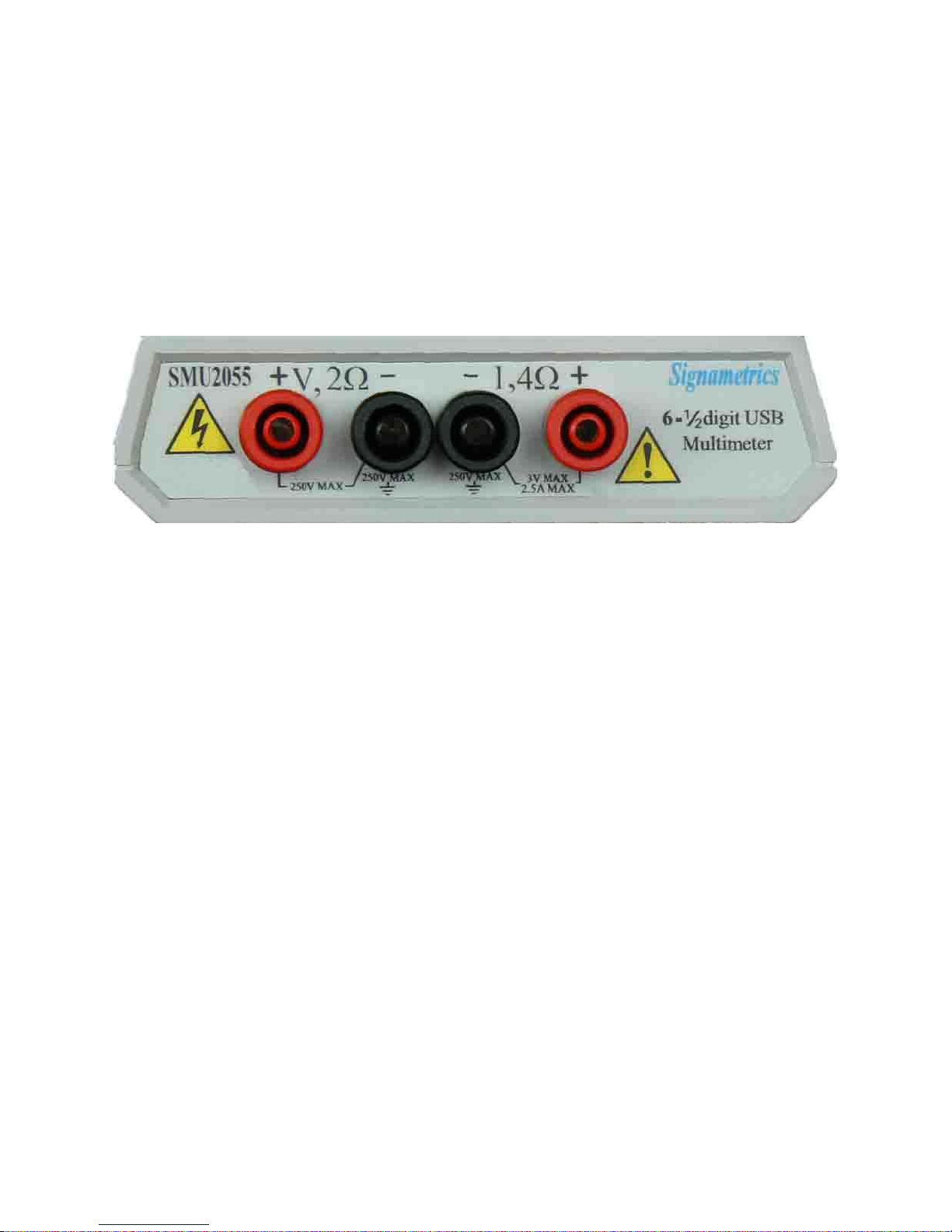
Figure 3-1. The DMM input connectors consist of four Banana jacks.
V, 2 + This is the positive terminal for all Volts, 2-Wire Resistance and diode test. When in 4-Wire
resistance measurement mode, it serves as the positive terminal of the current source. The maximum
input across V, 2 + and V, 2 - is 240 VDC or 240 VAC.
V, 2 - This is the negative terminal for all Volts, 2-Wire Resistance and diode test. When in 4-Wire
resistance measurement mode, it serves as the negative terminal of the current source. Do not float this
terminal or any other DMM terminal more than 240 VDC or 240 VAC above Earth Ground.
I , 4+ This is the positive terminal for all Current measurements. While in 4-Wire resistance
measurement mode it is the high sense. The maximum input across I, 4 + and I, 4 - is 2.5 A. Do not
apply more than 5 V peak across the I,4+ and I,4- terminals.
I,4 - This is the negative terminal for Current measurements. While in 4-Wire resistance measurement
mode it serves as the low sense. The maximum input across I, 4W + and I, 4W - is 2.5 A. Do not
apply more than 5 V peak across these two terminals.
The I,4 - Current function is protected by a 2.5 A, 250 V Fast Blow fuse (PCT type).
3.6 DMM Rear Panel
The rear panel includes various compliance and warning text and graphics, the unit serial number, its
modle number and the installed options. The USB connector provides for both, compueter interface and
power to run the DMM..
15 Signametrics
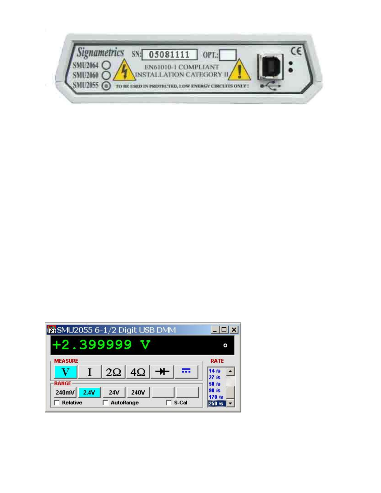
Figure 3-2. The Rear panel has the USB BF type connector. Compatible with BM cable.
3.7 Starting the Control Panel
You can verify the installation and gain familiarity with the DMM by exercising its measurement
functions using the Windows based Control Panel. To run the control panel, StartSMU2060 Series
MultimetersSMU2064 Multimeter. If you do not hear the relays click, it is most likely due to an
installation error. Another possible source for an error is that the SM60CAL.DAT file does not
correspond to the installed DMM.
When the DMM is started for the first time, it takes a few extra seconds to extract its calibration data from
the on-board memory, and write it to the calibration file C:\SM60CAL.DAT
The Control Panel is operated with a mouse. All functions are accessed using the left mouse button.
When the DMM is operated at very slow reading rates, you may have to hold down the left mouse button
longer than usual for the program to acknowledge the mouse click.
Note: The SMU2055 front panelstarts up in DCV, and 240 V range. If the DMM is operated in
Autorange, with an open input, it will switch between the 2.4V and 24V ranges every few seconds, as a
range change occurs. This is perfectly normal wth high end DMM’s such as the SM2055. This
phenomenon is caused by the virtually infinite input impedance of the 2.4V DC range. On these ranges,
an open input will read whatever charge is associated with the signal conditioning of the DMM. As this
electrical charge changes, the SM2055 will change ranges, causing the range switching. This is normal.
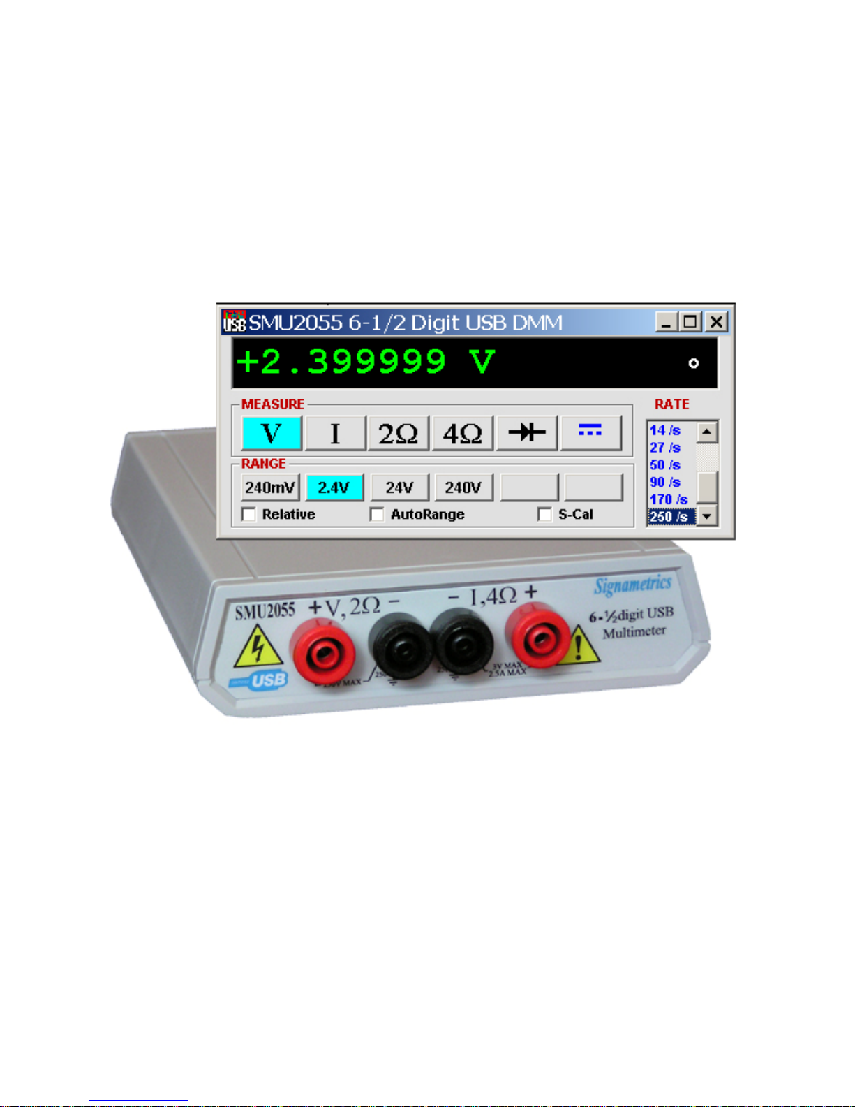
3.8 Using the Control Panel
Figure 3-2. The Control Panel. The two main groups include Measurement Function and Range buttons.
The Range buttons are context sensitive such that only “240m, 2.4, 24 and 240 appear when in a Voltage
Measurement Function is selected, and 2.4m, 24m, 240m and 2.4 appear when a Current Measurement
Function is selected, etc.
Signametrics 16

Note: All of the controls described below correspond to their respective software function, which can be
invoked within your control software or as objects in a visual programming environment. The software
command language provides a powerful set of capabilities. Some of the functions are not included in the
control panel, but are in the software.
DC/AC This function switches between DC and AC. This is applicable for the Voltage and Current
DMM functions.
Relative This is the Relative function. When activated, the last reading is stored and subtracted from all
subsequent readings. This is a very important function when making low-level DCV measurements, or in
2W. For example, when using 2W, you can null out lead resistance by shorting the leads together and
clicking on Relative. When making low level DC voltage measurements (e.g., in the V region), first
apply a copper short to the V, + & - input terminals, allow the reading to stabilize for a few seconds,
and click on Relative. This will correct for any internal offsets. The Relative button can also be used in
the Percent and dB deviation displays (shown below), which are activated using the T
ools in the top
menu.
Rate Box: Controls the DMM Measurement rate. As rate decreases, the measurement noise decreases.
Also consider the power line frequency (50/60 Hz) of operation when setting it, as certain rates have
better noise rejection at either 50 or 60 Hz. (See “Specifications” for details.). When measuring VAC
values, there is no point setting the Rate to a value greater than 2rps.
Range: Can be set to Autorange or manual by clicking on the appropriate range in the lower part of the
Windows panel. Autoranging is best used for bench top application. Autorange is not recommended
for automated test applications due to the uncertainty of the DMM range, as well as the extra time for
range changes. Locking a range is highly recommended when operating in an automated test system,
especially to speed up measurements. Another reason to lock a range is to control the input impedance in
DCV. The 240 mV and 2.4 V ranges have virtually infinite input impedance, while the 24 V and 240 V
ranges have 10 M input impedance.
S_Cal: This function is the System Calibration that corrects for internal gain, scale factor and zero
errors. The DMM does this by alternatively selecting its local DC reference and a zero input. It is
required at least once every day to meet the accuracy specifications. It is recommended that you also
perform this function whenever the external environment changes (e.g. the temperature in your work
environment changes by more than 5C. This function takes a few seconds to perform. Disconnect all
leads to the DMM before doing this operation. Keep in mind that this is not a substitute for periodic
calibration, which must be performed with external standards.
17 Signametrics

4.0 DMM Operation and Measurement Tutorial
Most of the measurement functions are accessible from the Windows Control Panel (Figure above). All of
the functions are included in the Windows DLL driver library. To gain familiarity with the DMM, run the
Windows ‘SETUP.EXE’ to install the software, then run the DMM, as described in the previous section.
This section describes in detail the DMM’s operation and measurement practices for best performance.
4.1 Voltage Measurement
Measures from 0.1 V to 240 VDC or VAC. Use the V, 2+ and V, 2- terminals, being certain to
always leave the I,4+ and I,4- terminals disconnected. Use the AC/DC button on the Control Panel
to switch between AC and DC.
Making Voltage Measurements is straightforward. The following tips will allow you to make the most
accurate voltage measurements.
4.1.1 DC Voltage Measurements
When making very low-level DCV measurements (<1 mV), you should first place a copper wire shorting
plug across the V, 2 + and V, 2 - terminals and perform Relative operation to eliminate zero errors.
A common source of error can come from your test leads, which can introduce several Volts of error due
to thermal voltages. To minimize thermal voltaic effects, after handling the test leads; you should wait a
few seconds before making measurements. Signametrics offers several high quality probes that are
optimal for low-level measurements.
Note: The front panel powers up in 2rps, DCV, 240 V range. If the DMM is operated in Autorange, with
an open input, The DMM will keep changing ranges. This is perfectly normal with ultra high impedance
DMM’. The virtually infinite input impedance of the 240 mV and 2.4 V DCV ranges causes this
phenomenon. On these ranges, an open input will read whatever charge is associated with the signal
conditioning of the DMM. As this electrical charge accumulates, the DMM will change ranges.
4.1.2 True RMS AC Voltage Measurements
ACV is specified for signals greater than 1mV, from 10 Hz to 50 kHz. The ACV function is AC coupled,
and measures the true RMS value of the waveform. As with virtually all true-RMS measuring
meters, the DMM may not read a perfect zero with a shorted input. This is normal.
ACV measurements, if possible, should have the NEUTRAL or GROUND attached to the V,2 -
terminal. This prevents any “Common Mode” problems from occurring (Common Mode refers to
floating the DMM V,2- above Earth Ground.) Common Mode problems can result in noisy readings,
or even cause the PC to hang-up under high V X Hz input conditions. In many systems, grounding the
source to be measured at Earth Ground (being certain to avoid any ground loops) can give better results.
The settling time and low frequency limits of the RMS functions (AC Voltage and current) are effected
by both, the value of the input as a percentage of range, and the frequency of the signal.
Take into account the amount of time it takes for the RMS circuit to settle. With a setteling time of 0.5s,
you may use a measurement rate of 2 readings/s and take two readings. The first will provide the 0.5s to
settele, and the second will make a stable reading. Do not average since the first reading will introduce an
error.
For improved accuracy and stability while measuring low frequency signals, the measurement time
(1/rate) should be at least ten (10) times the period of the measured signal.
4.2 Current Measurements
The DMM measures AC and DC currents between 100 A and 2.5 A. Use the +I, 4W terminals, being
certain to always leave all other terminals disconnected. Use the AC/DC button to switch between AC
and DC. The AC current is an AC coupled True RMS measurement function. See figure 4-2 for
connection.
Signametrics 18

The Current functions are protected with a 2.5 A, 250 V fuse internal to the DMM. The 2.4mA and 24mA
ranges utilize a 10 shunt, while the 240mA and 2.4A ranges use a 0.1 shunt. In addition to the shunt
resistors, there is some additional parasitic resistance in the current measurement path associated with the
fuse and the internal wiring. The maximum burden voltage is about 250mV.
Warning! Applying voltages greater than 35 V to the I+, I- terminals can cause personal injury and/or
damage to your DMM! Think before applying any inputs to these terminals!
4.2.1 Improving DC Current Measurements
When making sensitive DC current measurements disconnect all terminals not associated with the
measurement. User the Relative function while in the desired DC current range to zero out any residual
error. Using the S-Cal (DMMCalibrate ()) prior to activating Relative will improve accuracy further.
Although the DMM is designed to withstand up-to 2.4A indefinitely, be aware that excessive heat may be
generated when measuring higher AC or DC currents. If allowed to rise this heat may adversely effect
subsequent measurements. In consideration with this effect, it is recommended that whenever practical,
higher current measurements be limited to short time intervals.
4.3 Resistance Measurements
The key for stable and accurate Resistance measurements, with low test voltage, is in the number of
current sources used. This DMM uses five. The V, 2 + provides the positive terminal and the V, 2-
negative terminal of the current source. The DMM measures resistance by forcing a current, and
measuring a voltage, which the DMM converts and displays as a resistance value. Most measurements
can be made in the 2-wire mode. The 4-wire ohms is used to make low value resistance measurements.
All resistance measurement modes are susceptible to Thermo-Voltaic (Thermal EMF) errors. See section
4.3.5 for details.
4.3.1 2-Wire Ohm Measurements
In the 2-Wire resistance measurement the DMM sources current and measure resuting voltage. The DMM
measure Resistance using six ranges; 240 to 24 M. Use the V,2+, V,2- terminals for this function.
Disconnect the I,2+ and I,2- terminals in order to reduce error due to leakage and noise, as well as
better safety.
If the resistor to be measured is less than 24 k, you may null out any lead resistance errors by first
shorting the ends of the V,2+ and V,2- test leads together and performing a Relative operation
(DMMSetRelative under program control). Making measurements above 200 k, you should consider
shielded or twisted leads to minimize noise pickup. Further improvement can be achieved using guarding
(section 4.3.5).
It is a good idea to be aware of the test voltages, particularly when measuring a circuite that includes
semiconductors. To reduce this voltage, select a higher resistance range (lower current). For instance,
measuring 10k resistor using the 24k range (100uA), results in 1V test voltage, which will turn on
semiconductor junctions, resulting in lower resistance reading. To avoid this error, select the 240k range
(10uA), which will result in 100mV and will read the 10k a lot more accurately (see section 2.3 for
resistance ranges vs. current). For characterizing semiconductor part types, use the Diode measurement
function.
For applications requiring voltage and current controlled resistance measurements, use the SMU2064,
which has Extended Resistance Measurement function as well as active guarding.
4.3.2 4-Wire Ohm Measurements
4-wire Ohms measurements are advantageous for making measurements below 200 k, eliminating lead
resistance errors. The V,2+ and V,2- terminals apply a current source stimulus to the resistance, and
the I,4+ and I,4- Input terminals are the sense inputs. The Source + and Sense + leads are connected
to one side of the resistor, and the Source - and Sense - leads are connected to the other side. Both Sense
leads should be closest to the body of the resistor. See Figure 4-3.
19 Signametrics
 Loading...