

Signametrics Corporation SM4020, SM4042, SM4022, SM4040 Operator's Manual

Support Information Only
NOTICE: Signametrics was acquired by Agilent Technologies in October 2010. This document,
published prior to that date, is provided as a courtesy and may contain references to products or
services no longer supported by Agilent. For the latest information on Agilent’s modular test and
measurement products go to: www.agilent.com/find/modular
Or in the US, call Agilent Technologies at 1-800-829-4444 (8am-8pm EST)
For other Countries: www.agilent.com/find/contactus
© Agilent Technologies, Inc. November 8, 2011
5990-9491EN

Operator's Manual
Model SM4020 20 Channels Relay Multiplexer
Model SM4022 20 Channels Instrumentation Relay
Multiplexer
Model SM4040 40 Channels Relay Multiplexer
Model SM4042 40 Channels Instrumentation Relay
Multiplexer
Signametrics Corporation
March, 2006

CAUTION
In no event shall Signametrics or its Representatives be liable for any consequential damages whatsoever (including,
without limitation, damages for loss of business profits, business interruption, loss of business information, or other
loss) arising out of the use of or inability to use Signametrics’ products, even if Signametrics has been advised of
the possibility of such damages. Because some states do not allow the exclusion or limitation of liability for
consequential damages, the above limitations may not apply to you.
© 2000 Signametrics Corp. Printed in the USA. All rights reserved. Contents of this publication must not be
reproduced in any form w
ithout the permission of Signametrics Corporation.
Signametrics 2

TABLE OF CONTENTS
1.0 INTRODUCTION.................................................................................................................................................5
1.1 S
AFETY CONSIDERATIONS
1.2 M
INIMUM REQUIREMENTS
1.3 D
ESCRIPTION
1.4 C
ONFIGURATIONS
1.5 S
ELF TEST AND CONTACT CLEANING
2.0 SPECIFICATIONS AND FEATURE TABLE...................................................................................................8
2.1 T
RIGGER INPUT
2.2 T
RIGGER OUTPUT
2.3 O
THER SPECIFICATIONS
3.0 GETTING STARTED...........................................................................................................................................9
3.1 S
ETTING THE SCANNER
3.2 I
NSTALLING THE SOFTWARE
3.3 I
NSTALLING THE SCANNER MODULE
3.4 S
CANNER CONNECTOR PIN-OUT
3.5 S
TARTING THE CONTROL PANEL
3.6 U
SING THE CONTROL PANEL
4.0 SCANNER TUTORIAL .....................................................................................................................................15
4.1 S
CANNER CONFIGURATIONS
4.1.1 Two Wire Multiplexing .......................................................................................................... 16
4.1.2 Four Wire Multiplexing .........................................................................................................16
4.1.3 Six Wire Multiplexing ............................................................................................................17
4.1.4 Two Groups Configuration....................................................................................................17
4.1.5 Four Groups Configuration...................................................................................................18
4.1.6 Disabled.................................................................................................................................18
4.2 S
CANNER OPERATIONS
4.2.1 Trigger Output.......................................................................................................................18
4.2.2 Trigger Input..........................................................................................................................19
4.2.3 Auto Scan Operation..............................................................................................................19
4.2.4 Triggered Auto Scan Operation .............................................................................................19
4.2.5 Triggered Scan Operation .....................................................................................................20
4.2.6 Single Step Scan Operation ...................................................................................................20
4.2.7 Scan List Operations..............................................................................................................21
4.2.8 Locating Shorted Channel .....................................................................................................21
4.2.9 Cleaning Relays Contacts......................................................................................................22
4.2.10 Integrity Test........................................................................................................................22
4.2.11 Self Tests ..............................................................................................................................22
4.2.12 Setting Actuation Time Parameter.......................................................................................22
4.2.13 Setting Step Time Parameter ...............................................................................................23
4.2.14 Thermocouple Temperature Measurements.........................................................................23
4.3 P
OLLED TYPE OPERATIONS
4.4 I
NTERFACING TO THE
4.4.1 Triggering the SM2040 DMMs..............................................................................................24
4.4.2 Multiplexing with the SM2040 DMMs...................................................................................24
4.4.3 Interface Commands and Timing ...........................................................................................24
4.5 S
INGLE ENDED APPLICATION EXAMPLE
4.5.1 Point to Point Configuration .................................................................................................25
4.5.2 An 84 Point, Single End Configuration .................................................................................26
..............................................................................................................................................6
.......................................................................................................................................7
..........................................................................................................................................8
.......................................................................................................................................9
..........................................................................................................................5
.........................................................................................................................5
.........................................................................................................7
.............................................................................................................................9
..............................................................................................................................9
.....................................................................................................................10
........................................................................................................10
...............................................................................................................10
..............................................................................................................13
....................................................................................................................14
.....................................................................................................................15
.............................................................................................................................18
......................................................................................................................23
SM2040
SERIES
6-1/2 D
IGIT
DMM........................................................................24
...................................................................................................25
5.0 SM4040 SCANNER FAMILY WINDOWS INTERFACE..............................................................................26
5.1 D
ISTRIBUTION FILES
................................................................................................................................26
3 Signametrics

5.2 U
SING THE
5.3 V
ISUAL BASIC FRONT PANEL APPLICATION
5.4 W
INDOWS
5.5 U
SING THE
5.6 W
INDOWS COMMAND LANGUAGE
SM4040 D
5.2.1 Multiple Card Operations under Windows............................................................................28
5.3.1 Visual Basic Simple Application............................................................................................29
DLL D
SM4040 DLL
SCANAbort......................................................................................................................................31
SCANAutoScan ...............................................................................................................................32
SCANCleanRelays...........................................................................................................................33
SCANClosePCI...............................................................................................................................34
SCANDelay.....................................................................................................................................34
SCANErrString ...............................................................................................................................35
SCANGetActuationTime ................................................................................................................. 36
SCANGetBusInfo.............................................................................................................................36
SCANGetConfig..............................................................................................................................37
SCANGetGrdVer.............................................................................................................................37
SCANGetHwVer..............................................................................................................................38
SCANGetID.....................................................................................................................................38
SCANGetManDate.......................................................................................................................... 39
SCANGetScanList...........................................................................................................................39
SCANGetShortedChannel...............................................................................................................40
SCANGetStepTime..........................................................................................................................40
SCANGetTriggerIn .........................................................................................................................41
SCANGetType................................................................................................................................. 41
SCANGetVer...................................................................................................................................42
SCANInit.........................................................................................................................................42
SCANIsInitialized............................................................................................................................43
SCANOpenAllChannels ..................................................................................................................43
SCANOpenPCI................................................................................................................................44
SCANReady.....................................................................................................................................44
SCANSelectChannel........................................................................................................................45
SCANSelectChannelCmd................................................................................................................46
SCANSetActuationTime ..................................................................................................................46
SCANSetChannelRelay ...................................................................................................................47
SCANSetConfig...............................................................................................................................48
SCANSetConfigRelay......................................................................................................................48
SCANSetScanList............................................................................................................................49
SCANSetStepTime...........................................................................................................................50
SCANSetTriggerOut........................................................................................................................50
SCANSetupStep...............................................................................................................................51
SCANStep........................................................................................................................................51
SCANStepCmd ................................................................................................................................52
SCANTerminate ..............................................................................................................................53
SCANTestChanIntegrity..................................................................................................................53
SCANTestChannelRelay .................................................................................................................54
SCANTestConfigRelay....................................................................................................................54
SCANTrigAutoScan.........................................................................................................................55
SCANTriggerInState.......................................................................................................................56
SCANTriggerOutState.....................................................................................................................56
SCANTrigScan................................................................................................................................57
RIVER WITH
EFAULT MODES AND PARAMETERS
WITH LABWINDOWS
C++
OR SIMILAR SOFTWARE
.............................................................................................29
..............................................................................30
/CVI® ............................................................................31
...........................................................................................................31
.............................................................27
6.0 ACCESSORIES...................................................................................................................................................59
7.0 WARRANTY AND SERVICE...........................................................................................................................59
Signametrics 4

1.0 Introduction
Congratulations! You have purchased a Personal Computer (PC) Plug-in instrument with analog and systems
performance that rivals the best, all-in-one box, instruments. The SM4040 series relay scanner/multiplexer are easy
to setup and use, have sophisticated analog and digital circuitry to provide very repeatable switching. Please take a
few moments and review this manual before installing and using this instrument.
This manual describes the SM4020, SM4022, SM4040, and SM4042 Scanners. Each delivers unmatched switching
performance in a PCI plug-in instrument. With a rich repertoire of functions, the SM4040 series out performs all
other plug-in Scanners, including most brand-name bench top units.
Note: In this manual, all references to the "SM4000" and “Scanner” applies to the SM4020, SM4022, SM4040, and
SM4042. Features unique to each product will be identified as such.
1.1 Safety Considerations
Safety Considerations
The SM4000 series of Scanners are capable of switching 110 VDC or 220, depending on model number,
across the High and Low terminals. They can also handle common mode signals that "float" the Scanner
above EARTH ground by up to 110 VDC or 220 VAC, depending on the model. When making common
mode switching, the majority of the circuits inside the Scanner are at the common mode voltage. These
voltages can be lethal and may KILL! During and after installing your Scanner, check to see that
there are no wires or ribbon cables from your PC trapped inside the Scanner.
The Scanner comes installed with four shields (bottom, top, and two edge strips) that must not be
removed for performance as well as safety reasons. Removal of these shields and/or improper
assembly of the shields can result in lethal voltages occurring within your PC. Be sure to check your
installation before closing the cover on your personal computer.
Warning
Check to see that no loose wires or ribbon cables infringe upon any of the internal circuits of the
Scanner, as this may apply lethal voltages to your computer, causing electrocution and/or damage to
your computer!
To avoid shock hazard, install the Scanner only into a computer that has its power connector
connected to a power receptacle with an earth safety ground.
When connecting to signals above 50 VDC or 40 VAC, only use Safety Test Leads and harnesses.
1.2 Minimum Requirements
The SM4040 series of system relays Scanners are plug-in modules that are compatible with IBM type personal
computers (PCs), from the 486 class to the Pentiums. They require a half-length expansion slot on the PCI bus. A
mouse must be installed when controlling the Scanner from the Windows Control Panel. The SM4040 comes with a
Windows' DLL, for operation with Windows' Version 95/98 and NT4.0, Windows 2000 or greater.
5 Signametrics

1.3 Description
The SM4020 and SM4022 are 20 channel models arranged in two groups of 10:1 differential channels. The
SM4040 and SM4042 are 40 channel models arranged in four groups of 10:1 differential channels. The “2” suffix
indicates an instrumentation quality scanning structure, while the “0” indicates standard general purpose scanning
structure. The Instrumentation models are necessary in applications requiring precision and low leakage. The most
outstanding feature of the Instrumentation models is a very low Thermal EMF, resulting is highly accurate Ohms,
low Voltage, temperature and other sensitive stimulus and measurements. The standard scanners in this family, the
SM4020 and SM4040, exhibit much lower Thermal EMF than most other plug-in relay scanners.
When using an SM2020 or an SM2040 series 5-1/2 and 6-1/2 DMMs, or similar DMM, it is necessary to use the
Instrumentation quality scanners in order to maintain full measurement accuracy.
These scanners are software configurable on the fly, and can handle several pre-defined switching configurations,
such as TwoWire, FourWire, SixWire, Universal, TwoGroups, FourGroups, and Disabled. In the TwoWire
configuration, the scanner acts like a 20 or 4 0 channel multiplexer. In the FourWire configuration, it automatically
selects two simultaneous channels, allowing a DMM or other device to connect to four individual lines. In the
SixWire configuration six wires, or three differential channels are selected automatically, providing such
applications as six wire guarded in circuit measurements. The Universal configuration turns the scanner into a
pseudo matrix structure, allowing any relay, including channel relays, tree relays and configuration relays, to be
closed or open, including multiple relays. The TwoGroups and FourGroups configurations split the Scanner into
several independent Two-Wire multiplexers.
Figure 1-1. Simplified diagram of the SM4000 relay scanner.
In the TwoWire, FourWire, SixWire, TwoGroups, and FourGroups configuration, the switching sequence includes
the opening of the previously closed channels and then closing of the selected channels. In the case where multiple
channels are supposed to be closed, such as in FourWire configuration, these channels are closed simultaneously so
that no additional time beyond the actuation time is consumed. Break-before-make operation is maintained due to a
high speed turns off circuit, which shuts off the active co il current very quickly as compared to the turn on time.
Signametrics 6

1.4 Configurations
In addition to the channel switching relays, the SM4000 series includes two sets of relays used for configuring of
the scanner. The configuration switches facilitate inter-group connections and the Tree relays provide isolation of
each of the group’s buses from their respective channel relays. These relays are automatically switched on the fly
when the scanner receives configuration commands or changes are required while selecting channels from various
groups. In cases where the pre-defined configurations (TwoWire, FourWire, SixWire, TwoGroups, and FourGroups)
do not meet the test needs, select the Universal configuration. It allows an unlimited control any of the configuration
and tree relays independently. Care must be taken however, since it does not offer the protection of the predefined
configurations. This could result in shorting some “hot” lines, constituting in potential hazard to the user from any
thing that is connected to the scanner and from the scanner itself. This could also lead to damaging the scanner or
anything connected to it.
1.5 Self Test and Contact Cleaning
In addition to the channel relays, Tree relays and Configu r ation relays, there are additional relays and circuit
components that handle the various tests built into the Scanners. The user does not have direct control of these
components.
The test connector is used in various self tests and cleaning operations of the Scanner. It is a Female DIN 96
ion connector which has 40 shorts across all Channels (Ch1Hi shorted to Ch1Lo etc.), and three shorts across
t
posi
the B-Bus, C-Bus and D-Bus. All other terminals, including the A-Bus must be left open. This Test Connector is
optionally available from Signametrics.
7 Signametrics

2.0 Specifications and Feature Table
Function SM4020
Standard
Scanner
Number of differential channels 20 40 20 40
Number of 10:1 groups two four two four
Scanning Arrangement Two groups of 10:1 differential Four groups of 10:1 differential
Thermal EMF offset (
µV)
25 1.5 25 1.5
Maximum Switching DC Voltage (V) 110 220 110 220
Maximum Switching AC Voltage (V) 110 250 110 250
Maximum Switching Current (A) 1 1 1 1
Maximum Switching Current (A) 1 1 1 1
Typical inter-channel Capacitance 15pf 15pf 15pf 15pf
Insulation between open contacts (
Insulation; contacts to coils
Insulation; adjacent channels
(MΩ)
(MΩ)
MΩ,)
No Load Life 2X10
Loaded Life @ 50Vdc, 0.1A 3X10
Trigger input
Trigger output
>100 >1,000 >100 >1,000
>100 >1,000 >100 >1,000
>100 >1,000 >100 >1,000
7
5
√ √ √ √
√ √ √ √
Thermocouple Cold Junction Capable
Typical Closure Time (ms) 12 4 12 4
Typical Release Time (ms) 5 2 5 2
Actuation Time (ms) [1] 15 5 15 5
Actuation Time Settable Range (ms) 1 to 850 in 0.25 steps
AutoScan Period Range (ms) 1 to 850 in 0.25 steps
Available Configurations 2-wire, 4-wire,
universal, two-
groups
Available Scan Groups A and B A, B, C and D A and B A, B, C and D
Isolated Relay Coil Drive
Maximum number of relays closed All All All 40
High Ohms range 1,000 Meg
[1] Actuation time is the time it takes to open any closed relays, and close the selected relay.
Table 2-1. Specifications and Feature table.
SM4022
Instrumentation
Scanner
8
10
6
10
√
2-wire, 4-wire, 6-
re, uni
wi
versal,
two-groups, four-
groups
√
SM4040
Standard
Scanner
7
2X10
5
3X10
2-wire, 4-wire,
versal
uni
, two-
groups
SM4042
Instrumentation
Scanner
8
10
6
10
√
2-wire, 4-wire, 6-
i
re, universal,
w
two-groups, four-
groups
√
√
2.1 Trigger Input
Input Characteristics
• Input LED (nomi
• Input Signal requirements >2.5 V, < 10 V to activ
• Isolation O
Signametrics 8
nal 1.7V drop at 1mA) with a series 1kΩ resistor.
p
tically Isolated from all other circuitry. Common line with Trigger Output.
ate. < 1V to deactivate.
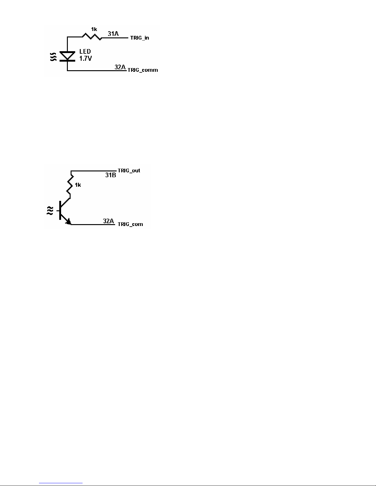
Figure 2-1. Trigger input equivalent circuit.
2.2 Trigger Output
Output Characteristics
• Output Circuit Open collector of a NPN transistor (nominal 0.4V saturation voltage) in series with 1kΩ
resistor.
• Collector Emiter Voltage < 30 V
• Output Current < 4 mA
• Reverse Voltage < 7V
• Isolation Optically Isolated from all other circuitry. Common line with Trigger Input.
Figure 2-2. Trigger Output Optical Isolator NPN circuit.
2.3 Other Specifications
Hardware Interface PCI Bus
Safety Designed to IEC 1010-1, Installation Category I.
Temperature Range 0°C to 50°C, operating
Size 9.2” X 4.4”
Power +5 volts, 550 mA maximum
Note: Signametrics reserves the right to make changes in materials, specifications, product functionality, or
accessories without notice.
3.0 Getting Started
After unpacking the Scanner, please inspect for any shipping damage that may have occurred, and report any claims
to your transportation carrier.
The Scanner package is shipped with the Scanner module, four floppy disks containing software drivers, user
interface panel, and this Operator's manual.
3.1 Setting the Scanner
The SM4040 series Relay Scanners are PCI plug-and-play devices and do not require any switch settings, or any
other adjustments to the hardware prior to installation.
9 Signametrics

3.2 Installing the Software
It is best to first plug the Relay Scanner into the PC chassis, and follow the instructions on the screen for ‘New
Hardware Found’. . The first time you power up your computer with the Scanner installed, your computer will
detect the new Scanner and prompt you for a driver. The driver your computer requires is on Disk 1 (SM4040.inf).
Guide the computer to search for device driver on Disk1. Next run ‘setup’ provided in Disk1.
After the computer completes its boot process run the ‘SETUP’ program provided on Disk 1, to install the software.
This takes care of all installation and registration requirements of the software.
3.3 Installing the Scanner Module
Warning
To avoid shock hazard, install the Scanner only into a personal computer that has its power line connector
connected to an AC receptacle with an Earth Safety ground.
After installation, check to see that no loose wires or ribbon cables infringe upon any of the internal circuits
of the Scanner, as this may apply measurement voltages to your computer, causing personal injury and/or
damage to your computer!
Caution: Only install the Scanner module with the power turned OFF to the PC!
Use extreme care when plugging the Scanner module(s) into a PCI bus slot. The Scanner comes a DIN 96 pin
connector. Because of its necessary size, it is a tight fit in many PC chassis. Insert the bracket end of the Scanner
into your PC first, watching for any interference between the DIN 96 connector and your PC chassis. “Sliding” the
bracket end of the Scanner into the chassis may be helpful. Be patient! You should only have to install it once!
3.4 Scanner Connector Pin-out
Before using the Scanner, please take a few moments and review this section to understand where the multiplexed
and common signals are located in the DIN 96 position male connector are located. Under no circumstances
should voltage and current limits exceed the specified values, as personal injury or damage to the instrument,
your computer or application may result.
Figure 3-1. The Scanner’s DIN 96 connector, facing the bracket.
Pin # Label Description Pin # Label Description
1C Ch11Hi Channel 11 High 17C Ch31Hi Channel 31 High
Signametrics 10

1B Ch10Hi Channel 10 High 17B Ch25Lo Channel 25 Low
1A Ch17Lo Channel 17 Low 17A Ch26Lo Channel 26 Low
2C Ch18Lo Channel 18 High 18C Ch31Lo Channel 31 Low
2B Ch1Hi Channel 1 High 18B Ch27Hi Channel 27 High
2A Ch2Hi Channel 2 High 18A Ch27Lo Channel 27 Low
3C Ch18Hi Channel 18 High 19C Ch33Hi Channel 33 High
3B Ch4Lo Channel 4 Low 19B Ch28Hi Channel 28 High
3A Ch2Lo Channel 2 Low 19A Ch15Lo Channel 15 Low
4C Ch19Hi Channel 19 High 20C Ch33Lo Channel 33 Low
4B Ch1Lo Channel 1 Low 20B Ch17Hi Channel 17 High
4A Ch6Lo Channel 6 Low 20A Ch29Hi Channel 29 High
5C Ch19Lo Channel 19 Low 21C Ch36Lo Channel 36 Low
5B Ch4Hi Channel 4 High 21B Ch28Lo Channel 28 Low
5A Ch11Lo Channel 11 Low 21A Ch29Lo Channel 29 Low
6C Ch5Hi Channel 5 High 22C Ch39Lo Channel 39 Low
6B Ch8Hi Channel 8 High 22B Ch30Hi Channel 30 High
6A Ch7Lo Channel 7 Low 22A Ch30Lo Channel 30 Low
7C Ch16Lo Channel 16 Low 23C Ch37Hi Channel 37 High
7B Ch12Hi Channel 12 High 23B Ch32Hi Channel 32 High
7A Ch7Hi Channel 7 High 23A Ch35Hi Channel 35 High
8C Ch12Lo Channel 12 Low 24C Ch38Hi Channel 38 High
8B Ch9Lo Channel 9 Low 24B Ch32Lo Channel 32 Low
8A Ch13Hi Channel 13 High 24A Ch34Lo Channel 34 Low
9C Ch5Lo Channel 5 Low 25C Ch40Hi Channel 40 High
9B Ch13Lo Channel 13 Low 25B Ch37Lo Channel 37 Low
9A Ch14Hi Channel 14 High 25A Ch34Hi Channel 34 High
10C Ch3Hi Channel 3 High 26C Ch38Lo Channel 38 Low
10B Ch8Lo Channel 8 Low 26B Ch35Lo Channel 35 Low
10A Ch9Hi Channel 9 High 26A Ch36Hi Channel 36 High
11C Ch6Hi Channel 6 High 27C Ch39Hi Channel 39 High
11B Ch10Lo Channel 10 Low 27B Ch40Lo Channel 40 Low [1]
11A Ch15Hi Channel 15 High 27A
12C Ch20Hi Channel 20 High 28C
12B Ch16Hi Channel 16 High 28B
12A Ch14Lo Channel 14 Low 28A BHi B-Bus High
13C Ch21Lo Channel 21 Low 29C BLo B-Bus Low
13B Ch22Hi Channel 22 High 29B CHi C-Bus High
13A Ch21Hi Channel 21 High 29A DHi D-Bus High [1]
14C Ch20Lo Channel 20 Low 30C CLo C-Bus Low
14B Ch23Hi Channel 23 High 30B AHi A-Bus High
14A Ch23Lo Channel 23 Low 30A ALo A-Bus Low
15C Ch24Hi Channel 24 High 31C DLo D-Bus Low [1]
15B Ch22Lo Channel 22 Low 31B TRIG_out Trigger open collector out.
15A Ch24Lo Channel 24 Low 31A TRIG_in Trigger TTL input
16C Ch26Hi Channel 26 High 32C +5V +5V special supply
16B Ch3Lo Channel 3 Low 32B Common Return for +5V supply
16A Ch25Hi Channel 25 High 32A TRIG_com Trig. input and output comn
[1] D-Bus is not available when using an Isothermal Terminal Block.
Table 3-1. The Scanner’s DIN 96 connector pin assignments.
11 Signametrics
ChxHi, ChxLo - These are the channel positive and negative terminals for all group channels, respectively. It starts
with Ch1Hi/Lo and ends with Ch20Hi/Lo with the 20 Channel scanners and Ch40Hi/Lo for the 40 Channel models.
Depending on the Scanner configuration, these lines are routed to the bus terminals AHi/Lo, BHi/Lo, CHi/Lo, or
DHi/Lo.
AHi, ALo - These are the A-bus positive and negative terminals respectively. The chann els positive and negative
lines may be routed to these lines depending on Scanner configuration. In the Universal mode, it is also possible to
route bus pairs to other bus pairs.
BHi, BLo - These are the B-bus positive and negative terminals respectively. The channels p ositive and negative
lines may be routed to these lines depending on Scanner configuration. In the Universal mode, it is also possible to
route bus pairs to other bus pairs.
CHi, CLo - These are the C-bus positive and negative terminals respectively. The channels positive and negative
lines may be routed to these lines depending on Scanner configuration. In the Universal mode, it is also possible to
route bus pairs to other bus pairs.
DHi, DLo - These are the D-bus positive and negative terminals respectively. The chann el positive and negative
lines may be routed to these lines depending on Scanner configuration. In the Universal mode, it is also possible to
route bus pairs to other bus pairs. It is important to note that when using the Isothermal Block the DHi and DLo
terminals should not be used, and a configuration involving them should not be selected. Therefore configurations
such as FourGroups or SixWire should not be selected, and when selecting Universal configuration, care must be
taken not to include these terminals.
TRIG_com - This is the TRIG_in and TRIG_out return terminal. Both of these signals are referenced to it. All
three signals associated with the trigger circuitry, TRIG_com, TRIG_in, and TRIG_out are optically isolated from
the rest of the terminals in the DIN 96 connector.
Figure 3-2. The trigger input and output lines are isolated by an optical isolators.
TRIG_in - This is the trigger input signal. It requires TTL or CMOS level (at least 2.5V) to activate the trigger
input. A series 1k removes the need to add external resistor and allows direct connection to a TTL or CMOS logic
source. It is referenced to the TRIG_com line.
TRIG_out - This is the trigger output signal. It is an open collector signal with 1k resistor in series. It will drive a
CMOS or TTL line provided it is connected to an appropriate positive supply (from 3V to 10V). It is referenced to
the TRIG_ com line.
+5V - This is a 5V supply line. It is designed to support the optional active Isothermal Block. It may also be used to
power the TRIG_out signal. When using it to power TRIG_out, it is recommended that a 10k be connected from
TRIG_out to it as in Figure 3-3. This supply may vary between 4.7V to 5.7V, and its usage should be limited to no
more than 10mA. This supply is isolated from the rest of the signals in the DIN 96 connector. This signal is
referenced to the Common line.
Signametrics 12
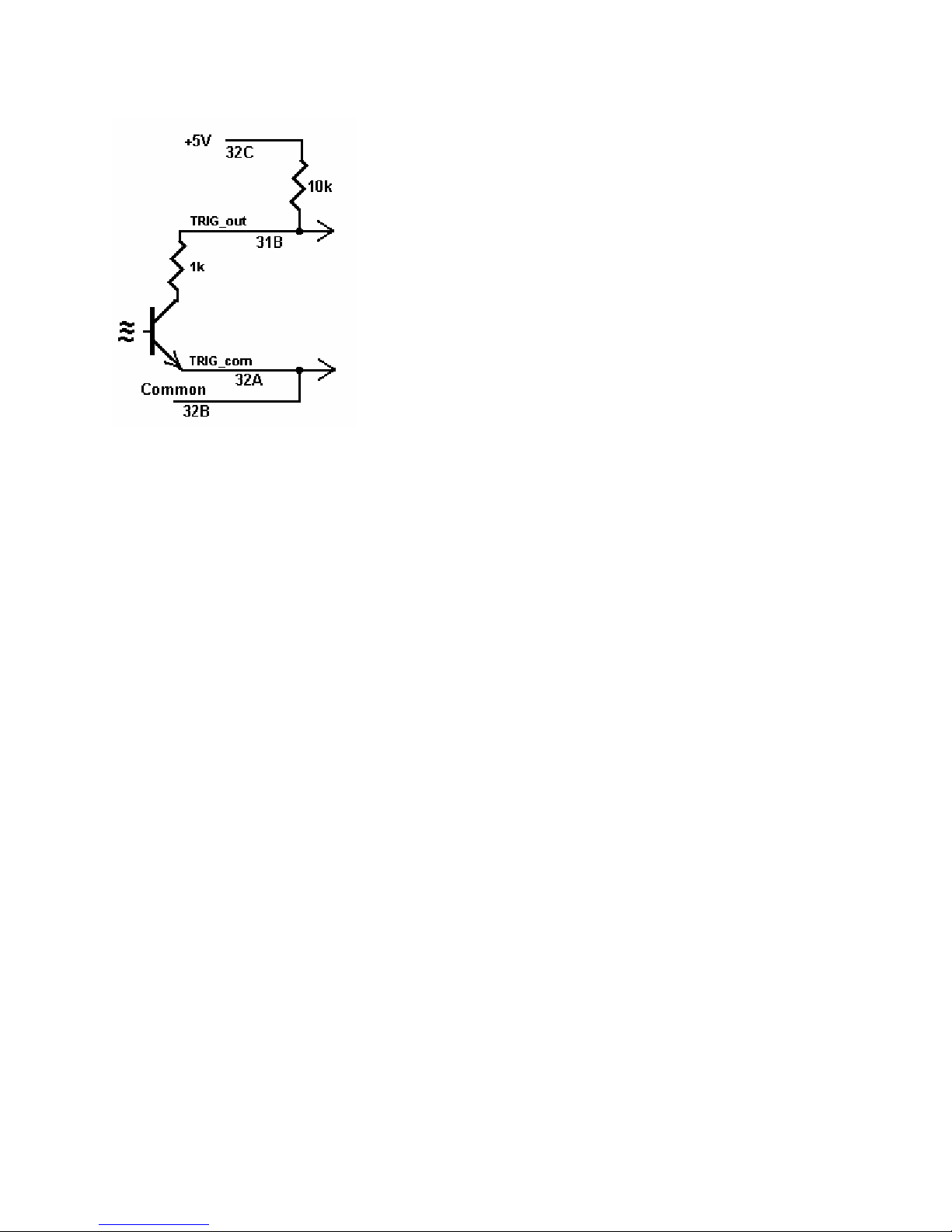
Common - This is the return line for the +5V supply. Since TRIG_com and Common are isolated from each other,
they must be connected as in Figure 3-3 if the +5V is used to power TRIG_com. This supply return is isolated from
the rest of the signals in the DIN 96 connector.
Figure 3-3. Trigger out may use the +5V supply provided for generating CMOS logic output.
3.5 Starting the Control Panel
After installing the software, you can verify the installation an d gain familiarity with the Scanner by exercising its
measurement functions using the Windows based Control Panel. To run the control panel, double click the
‘SM4040.EXE’ icon. If you do not hear the relays click, you may have an installation error.
The Control Panel is operated with a mouse. All functions are accessed using the left mouse button.
Note: The SM4000 front panel powers up in Disabled mode, with all relays open.
13 Signametrics

3.6 Using the Control Panel
Figure 3-2. The Control Panel for the SM4040. The three main groups include the relays buttons, the configuration
selection options, and the main menu.
Note: All of the controls described below correspond to their respective software function, which can be invoked
within your control software or as objects in a visual programming environment. Using the software command
language of the SM4000 allows additional capabilities and functions that are not included in the control panel
above.
Relay Buttons - These buttons are context sensitive. Depending on the selected Configuration, these buttons allow
the closing and opening of the various channel relays. In the Universal configuration, the user has control over all
relays. In the FourWire and SixWire configurations, two and three relays are activated simultaneously. In the
TwoWire, FourWire, SixWire, TwoGroups and FourGroups function switches between DC and AC.
Edit Scanner Parameters - This panel provides means to enter the Relay Actuation time and the Step Times, as
well as the total number of steps in an AutoScan.
ScanList Editor - This panel provides means to edit the contents of the ScanList.
Signametrics 14

Configuration Option Checks - This section of the main panel allows the selection of one out of all of the possible
pre defined configurations. On power up, the configuration is set to Disabled. Possible selections include Disabled,
TwoWire, FourWire, SixWire, Universal, TwoGroups, and FourGroups.
dit Menu - This menu item has three selections, setting all parameters to their default value, opening the Edit
E
Scanner Parameter sub-panel, and opening the Scan List Editor sub-panels.
rigger Menu - This menu item controls the functionality of the scanner’s trigger input and output signals. It
T
enables or disabled the Trigger output, and sets the polarity of both Trigger input and output.
s Menu - This menu item provides access to some of the special test and cleaning tools. It includes the Self-
Tool
Cleaning function, the various self-tests, and the shorted input detector.
perations Menu - This menu item allows running some of the special scanner’s operations such as AutoScan,
O
Triggered Scan, Triggered Auto Scan, and the setting and monitoring of the Trigger output and trigger input
respectively.
4.0 Scanner Tutorial
Most of the SM4000 functions are accessible from the control panel described in the previous section. This section
describes in detail the Scanner’s operations and practices. To gain familiarity with the SM4000 series Scanners, run
the Windows ‘SETUP.EXE’ to install the software, then run the Scanner control panel to demonstrate its operations.
4.1 Scanner Configurations
The various configurations maybe experimented with using the control panel. Connect to the Scanner’s terminals to
the appropriate channels and bus lines, making sure not to exceed any of the specifications and limits. Use the
control panel’s option checks to select the desired operation mode, and the switch buttons to close or open the
appropriate channels.
There is a special function, included in the DLL, which sets the Scanner configuration on the fly. It is
SCANSetConfig(). The amount of time it takes to set a new configuration is the same as the set Actuation time. It is
important to note that the Scanner can function as a multiplexer, or as an uncommitted matrix switch. In the
TwoWire, FourWire, SixWire, TwoGroups, and FourGroups configurations the Scanner acts as a multiplexer. This
means that when a channel is selected, all other channels in the group are opened prior to closing the selected
channel. For instance, the SM4042 in FourWire configuration, with Ch1 and Ch21 closed, will respond to ‘select
Ch2’ command by first opening Ch1 and Ch21, then it will close Ch2 and Ch22. All this will be done within the
specified actuation time.
15 Signametrics
4.1.1 Two Wire Multiplexing
In the TwoWire multiplexed configuration, the SM4000 family first opens all channels, then it connects the Hi and
Lo terminals of the selected channel, to the Hi and Lo terminals of the A-bus. The SM4020 and SM4022 route Ch1
through Ch20, and the SM2040 and SM2042 can route Ch1 to Ch40 to the A-bus. Selecting Ch1 will result in
Ch1Hi connected to A-bus Hi and Ch1Lo connected to A-bus Lo.
When making very low level DCV measurements (<1 mV), you should use copper wires. A common source of
error can come from your test leads, which can introduce tens or hundreds of µVolts of error due to thermal
voltages (Thermal EMF or TEMF). To minimize thermo-voltaic effects, after handling the test leads, wait a while
for lead and terminal temperatures to equalize before attempting to make measurements. Signametrics offers
several high quality probes that are optimal for low level measurements. It is essential to select the right scan ner for
the job. Make sure the relay scanner selected has sufficiently low thermal EMF (offset) specification. The SM4022
and SM4042 are the best choices for low level voltage measurements, as well as for Ohms and temperature. It is not
unusual to find scanners with very high thermal voltages. The following table quantifies the effect of Thermal
TEMF on Ohms measurement in a typical DMM such as the SM2042. This holds for both, 2-Wire and 4-Wire
Ohms measurement:
SM2042
Range
33 Ω
330 Ω
3.3 kΩ
33 kΩ
330 kΩ
3.3 MΩ
33 MΩ
Table 4-1. The Scanner thermal EMF affect on Ohms measurement accuracy.
Ohms
Current
10 mA
1 mA
1 mA
100 uA
10 uA
1 uA
100 nA
DMM
Resolution
10 µΩ 100 µΩ 1 mΩ 10 mΩ
100 µΩ 1 mΩ 10 mΩ 100 mΩ
1 mΩ 1 mΩ 10 mΩ 100 mΩ
10 mΩ 10 mΩ 100 mΩ 1 Ω
100 mΩ 100 mΩ 1 Ω 10 Ω
1 Ω 1 Ω 10 Ω 100 Ω
100 Ω 10 Ω 100 Ω 1 kΩ
Error due to
1uV TEMF
Error due to
10uV TEMF
Error due to
100uV TEMF
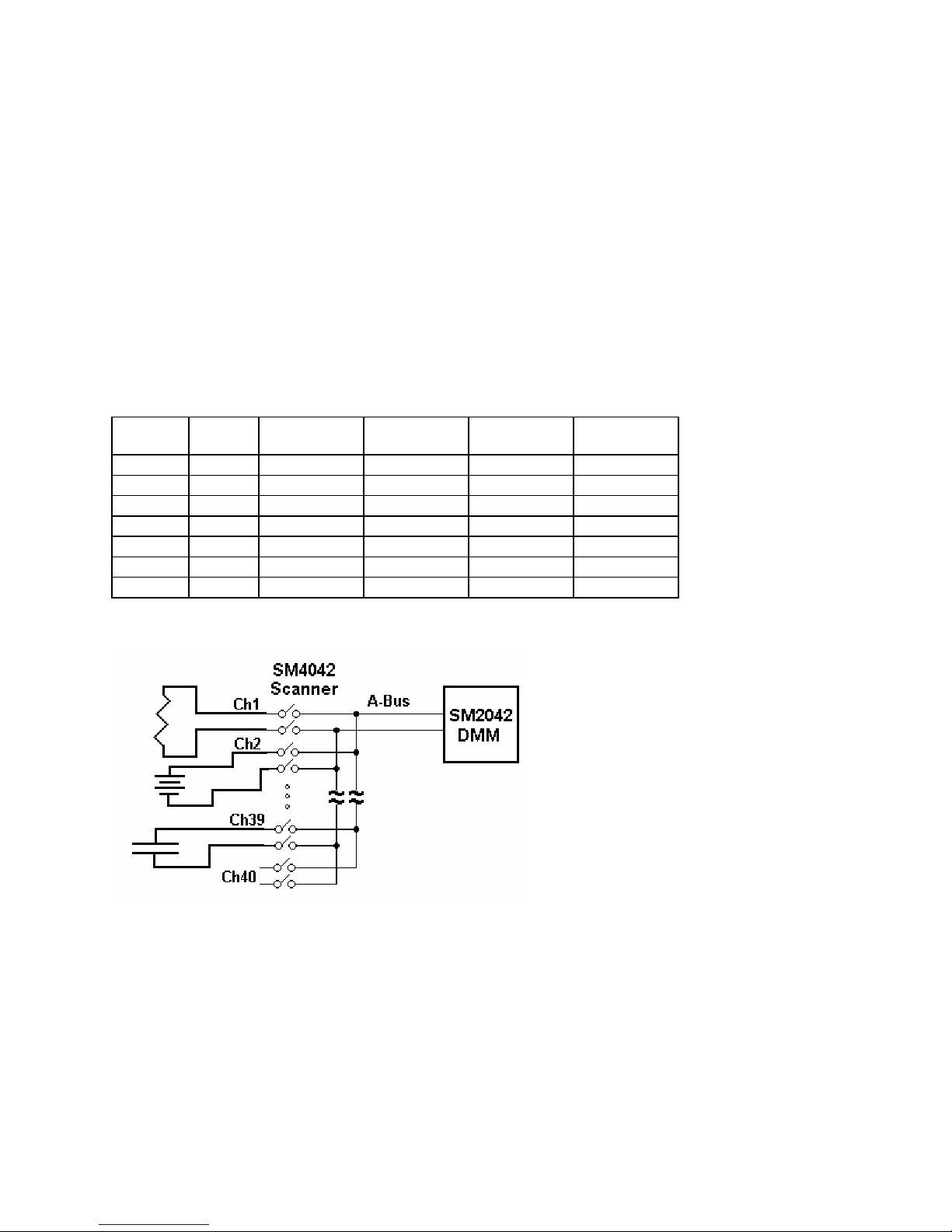
Figure 4-1. 40 Channel 2-Wire measurement application.
4.1.2 Four Wire Multiplexing
In the FourWire configuration, the SM4000 family connects simultaneously two channels. The SM4020 and
SM4022 route Ch1 through Ch10 to the A-bus, and the corresponding channels, Ch11 through Ch20, to the B-bus.
The SM4040 and SM4042 route Ch1 through Ch20 to the A-bus, and the corresponding channels, Ch21 through
Ch40 to the C-bus. To measure a resistor using Kelvin connection, the A-bus can be connected to the DMM source
leads and the B-bus to the sense leads. Make sure the polarity of the lines is consistent.
Signametrics 16
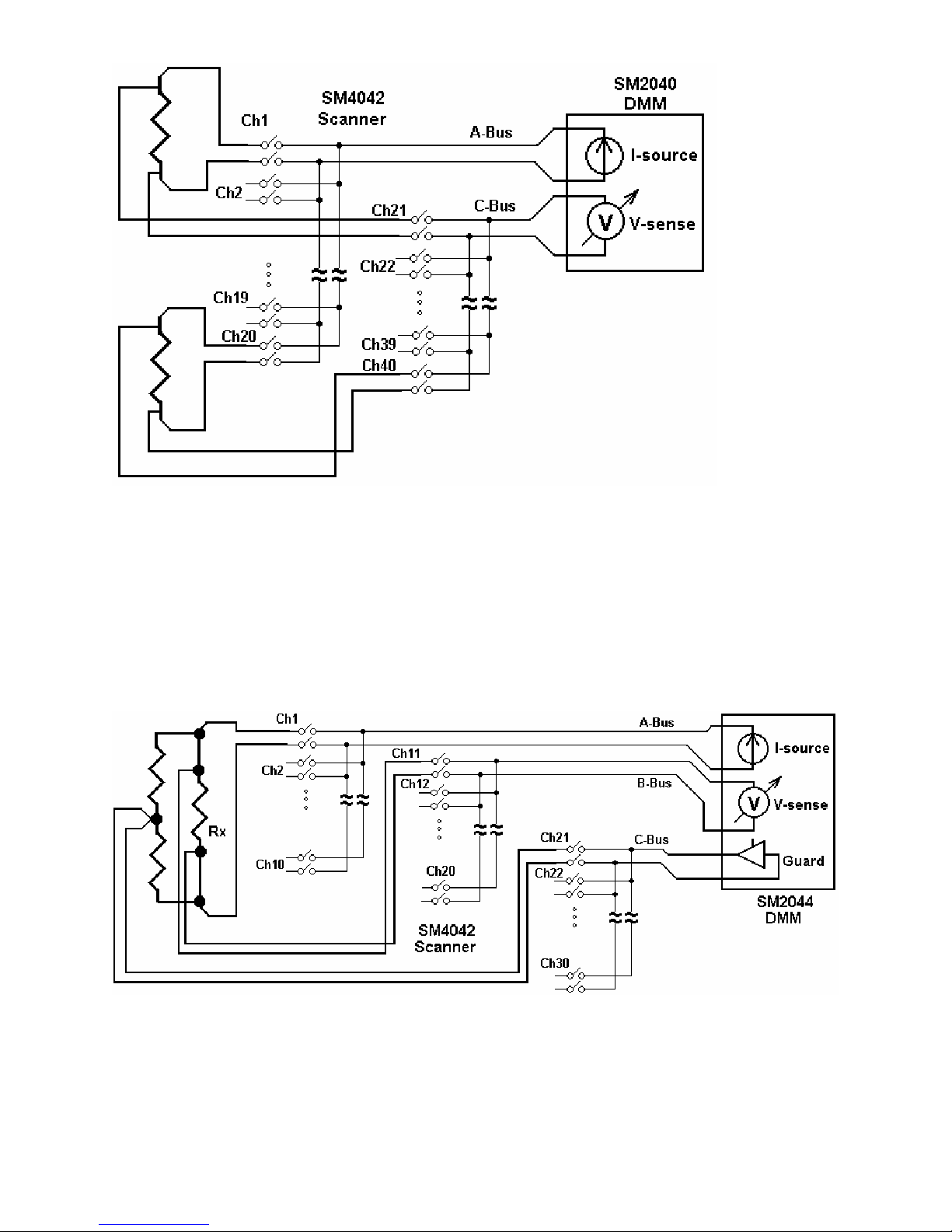
Figure 4-2. To perform 4-Wire resistance measurement with the SM4042, connect Ch1 and Ch21 to a resistor,
maintaining correct polarity.
4.1.3 Six Wire Multiplexing
In SixWire configuration, the SM4040 and SM4042 simultaneously connect one channel to the A-bus, one to the B-
bus and one to the C-bus. Selecting a channel automatically closes three channel relays. For instance, selecting
channel 2 results in the opening of all currently closed channel relays, followed by the closure of Ch2, Ch12, and
Ch22. Each is routed to the A-bus, B-bus, and C-bus, respectively. To measure a resistor using 6-Wire guarded
connection, the A-bus is connected to the DMM source leads, the B-bus to the sense leads and the C-bus to the
Guarded point. Make sure the polarity of the lines is consistent. It should e noted that the ‘D’ group, consisting of
Ch31 to Ch40, is available independently to provide additional 10 channels of 2-Wire multiplexing.
Figure 4-3. In the 6-Wire configuration, the three lead sets are switched simultaneously.
4.1.4 Two Groups Configuration
In the TwoGroup configuration, the SM4000 family provides two independent multiplexing groups. Both groups
function as two independent two wire multiplexers. W hen a channel is selected, any closed channel within that
group is opened; next, the selected channel is closed. The SM4020 and SM4022 route Ch1 through Ch10 to the A-
17 Signametrics
bus, forming one group, and, Ch11 through Ch20 to the B-bus, forming the second group. The SM4040 and
SM4042 route Ch1 to Ch20 to the A-bus forming the first group, and Ch21 through Ch40 to the C-bus, forming the
second group.
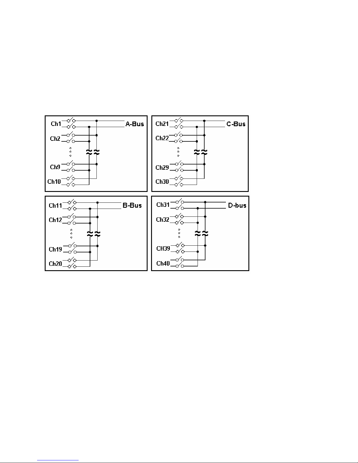
4.1.5 Four Groups Configuration
In the FourGroup configuration, the SM4040 and SM4042 provide four independent multiplexing groups. The
groups function as independent two wire multiplexers. When a channel is selected, any closed channel within the
selected group is opened, followed by the closure of the selected channel. It’s like having four individual switching
modules. Ch1 to Ch10 are routed to the A-bus forming the first group. Ch11 to Ch20 are routed to the B-bus
forming the second group. Ch21 to Ch30 are routed to the C-bus forming the third group. Ch31 through Ch40 are
routed to the D-bus to form the fourth group.
Figure 4-4. In the Four Groups configuration, four independent 2-Wire scanners are available.
4.1.6 Disabled
In the Disabled configuration, all relays, including channel and configuration relays are open. This is the default
configuration, selected on power up, or initialization.
4.2 Scanner Operations
In addition to basic scanner operations such as selecting channels, the SM4000 series has several built-in operations,
which it more versatile and a lot more capable. These operations include various self-diagnostics procedures,
contact cleaning, and auto scanning and interfacing to external test and measurement instruments.
4.2.1 Trigger Output
The trigger output line, TRIG_out, maybe enabled or disabled as well as set for a positive or negative polarity
using the SCANTriggerOutState() command. Under normal operation, the TRIG_out line is active for the
duration of the Actuation time. It maybe used to drive or synchronize other test equipment. If set to positive
polarity, a positive edge indicates the selected channel is closed and settled, provided the correct Actuation time is
set (use SCANSetActuationTime() function to set it). The logic level of TRIG_out may be set high or low using
Signametrics 18
 Loading...