


Operator's Manual
Model SM2060 7½ Digit Digital PCI Multimeter
Model SMX2060 7½ Digit Digital PXI Multimeter
Model SM2064 7½ Digit High Work Load PCI Digital Multimeter
Model SMX2064 7½ Digit High Work Load PXI Digital Multimeter
Signametrics Corporation
February 2005
Rev 1.1

CAUTION
In no event shall Signametrics or its Representatives are liable for any consequential damages whatsoever
(including, without limitation, damages for loss of business profits, business interruption, loss of business
information, or other loss) arising out of the use of or inability to use Signametrics products, even if Signametrics
has been advised of the possibility of such damages. Because some states do not allow the exclusion or limitation of
liability for consequential damages, the above limitations may not apply to you.
© 2004 Signametrics Corp. Printed in the USA. All rights reserved. Contents of this publication must not be
reproduced in any form without the permission of Signametrics Corporation.
Signametrics 2

TABLE OF CONTENTS
1.0 INTRODUCTION.................................................................................................................................................8
1.1 S
AFETY CONSIDERATIONS
1.2 M
INIMUM REQUIREMENTS
1.3 F
EATURE SET
2.0 SPECIFICATIONS.............................................................................................................................................10
2.1 DC V
2.2 DC C
2.3 R
2.4 AC V
2.5 AC C
2.6 L
2.7 RTD T
2.8 T
2.9 A
2.10 T
2.11 T
2.12 M
2.13 S
2.14 A
2.15 O
OLTAGE MEASUREMENT
URRENT MEASUREMENT
ESISTANCE MEASUREMENTS
2.3.1 2-wire.....................................................................................................................................11
2.3.2 4-wire.....................................................................................................................................11
2.3.3 6-wire Guarded Resistance Measurement (SM2064)............................................................11
2.3.4 Extended Resistance Measurements (SM2064) .....................................................................12
OLTAGE MEASUREMENTS
2.4.1 AC Voltage True RMS Measurement.....................................................................................12
2.4.2 AC Peak-to-Peak Measurement (SM2064)............................................................................14
2.4.3 AC Crest Factor Measurement (SM2064) .............................................................................15
2.4.4 AC Median Value Measurement (SM2064)...........................................................................15
URRENT MEASUREMENT
EAKAGE MEASUREMENT
HERMOCOUPLE TEMPERATURE MEASUREMENT
DDITIONAL COMPONENT MEASUREMENT CAPABILITY
2.9.1 Diode Characterization .........................................................................................................17
2.9.2 Capacitance, Ramp Method (SM2064)..................................................................................17
2.9.3 Capacitance, In-Circuit Method (SM2064)..........................................................................19
2.9.4 Inductance Measurement (SM2064)......................................................................................19
IME MEASUREMENTS
2.10.1 Threshold DAC ....................................................................................................................19
2.10.2 Frequency and Period Measurement...................................................................................20
2.10.3 Duty Cycle Measurement.....................................................................................................20
2.10.4 Pulse Width..........................................................................................................................20
2.10.5 Totalizer...............................................................................................................................21
RIGGER FUNCTIONS
2.11.1 External Hardware Trigger (at DIN-7 connector) ..............................................................21
2.11.2 Analog Threshold Trigger....................................................................................................21
2.11.3 Delayed Hardware Trigger..................................................................................................21
EASUREMENT APERTURE AND READ INTERVAL
OURCE FUNCTIONS
2.13.1 DC Voltage Source ..............................................................................................................24
2.13.2 AC Voltage Source...............................................................................................................24
2.13.3 DC Current Source..............................................................................................................24
CCURACY NOTES
THER SPECIFICATIONS
.............................................................................................................................................9
EMPERATURE MEASUREMENT
..........................................................................................................................8
.........................................................................................................................9
.................................................................................................................10
.................................................................................................................10
..................................................................................................................11
...............................................................................................................12
, T
RUE
RMS .............................................................................................15
(SM2064) ......................................................................................................16
(SM2064) .....................................................................................16
(SM2064) ...................................................................17
..........................................................................17
...........................................................................................................................19
.............................................................................................................................21
..................................................................................21
(SMX2064)...........................................................................................................23
.................................................................................................................................24
.........................................................................................................................25
3.0 GETTING STARTED.........................................................................................................................................27
3.1 S
ETTING THE
3.2 I
NSTALLING THE
3.3 I
NSTALLING THE SOFTWARE
3.4 DMM I
3.5 S
TARTING THE CONTROL PANEL
3.6 U
SING THE CONTROL PANEL
4.0 DMM OPERATION AND MEASUREMENT TUTORIAL...........................................................................32
DMM .................................................................................................................................27
DMM M
NPUT CONNECTORS
ODULE
.............................................................................................................27
....................................................................................................................27
......................................................................................................................28
..............................................................................................................29
....................................................................................................................30
3 Signametrics

4.1 V
OLTAGE MEASUREMENT
4.1.1 DC Voltage Measurements ....................................................................................................32
4.1.2 True RMS AC Voltage Measurements ...................................................................................32
4.1.3 AC Peak-to-Peak and Crest Factor (SM2064)......................................................................33
4.1.4 AC Median Value Measurement (SM2064)...........................................................................33
4.2 C
URRENT MEASUREMENTS
4.2.1 Extended DC Current Measurements (SM2064) ...................................................................34
4.2.2 Improving DC Current Measurements ..................................................................................34
4.2.3 DC Current Measurements at a specific voltage...................................................................34
4.3 R
ESISTANCE MEASUREMENTS
4.3.1 2-Wire Ohm Measurements ...................................................................................................35
4.3.2 4-Wire Ohm Measurements ...................................................................................................35
4.3.3 Using Offset Ohms function (SM2064)..................................................................................36
4.3.4 6-wire Guarded Resistance Measurement (SM2064)............................................................36
4.3.5 Extended Resistance Measurements (SM2064) .....................................................................37
4.3.6 Effects of Thermo-Voltaic Offset ............................................................................................38
4.3.7 Guarding High Value Resistance Measurements (SM2064) .................................................39
4.4 L
EAKAGE MEASUREMENTS
4.5 M
EASUREMENT TIMING
4.5.1 Aperture.................................................................................................................................40
4.5.2 Read Interval..........................................................................................................................40
4.6 RTD T
4.7 I
4.8 D
4.9 C
4.10 IN-C
4.11 I
4.12 C
4.13 T
4.14 F
4.15 S
4.16 I
4.17 M
4.18 U
EMPERATURE MEASUREMENT
NTERNAL TEMPERATURE
IODE CHARACTERIZATION
APACITANCE MEASUREMENT
IRCUIT CAPACITANCE MEASUREMENT
NDUCTANCE MEASUREMENT
HARACTERISTIC IMPEDANCE MEASUREMENT
RIGGER OPERATION
4.13.1 External Hardware Trigger.................................................................................................44
4.13.2 Analog Threshold Trigger....................................................................................................45
4.13.3 Software Generated Triggered Operations..........................................................................45
REQUENCY AND TIME MEASUREMENTS
4.14.1 Threshold DAC ....................................................................................................................47
4.14.2 Frequency and Period Measurements .................................................................................48
4.14.3 Duty Cycle Measurement.....................................................................................................48
4.14.4 Pulse Width..........................................................................................................................48
4.14.5 Totalizer Event Counter.......................................................................................................48
OURCING FUNCTIONS
4.15.1 DC Voltage Source ..............................................................................................................49
4.15.2 AC Voltage Source...............................................................................................................50
4.15.3 DC Current Source..............................................................................................................51
4.15.4 Source Current - Measure Voltage......................................................................................51
NTERFACING TO THE
4.16.1 Triggering the SM2060 DMM’s...........................................................................................51
4.16.2 Multiplexing with the SM2060 DMM’s................................................................................52
4.16.3 Interface Commands and Timing .........................................................................................52
EASURING TEMPERATURE WITH THERMOCOUPLES
SING THE
PXI
BUS TRIGGER FACILITIES
4.18.1 Selecting PXI Trigger Outputs.............................................................................................53
4.18.2 Selecting PXI Trigger Inputs ...............................................................................................54
........................................................................................................................32
......................................................................................................................33
..................................................................................................................35
(SM2064)..................................................................................................... 39
...........................................................................................................................40
(SM2064) .......................................................................................................42
.....................................................................................................................42
(SM2064) ...............................................................................................43
(SM2064) ............................................................................................... 44
.............................................................................................................................44
(SM2064)..........................................................................................................49
SM4040
SERIES RELAY SCANNERS
(SM2064) .....................................................................................42
(SM2064) ..........................................................................43
(SM2064)..................................................................... 44
...............................................................................................47
......................................................................51
.............................................................................53
(SMX2064)..........................................................................53
5.0 WINDOWS INTERFACE..................................................................................................................................55
5.1 D
ISTRIBUTION FILES
5.2 U
SING THE
5.3 V
ISUAL BASIC FRONT PANEL APPLICATION
5.4 W
INDOWS
SM2060 D
5.2.1 Multiple Card Operations under Windows............................................................................57
5.3.1 Visual Basic Simple Application............................................................................................59
DLL D
EFAULT MODES AND PARAMETERS
Signametrics 4
................................................................................................................................55
RIVER WITH
C++
OR SIMILAR SOFTWARE
.............................................................................................58
............................................................57
.............................................................................60

5.5 U
SING THE
5.6 W
INDOWS COMMAND LANGUAGE
SM2060 DLL
DMMArmAnalogTrigger ................................................................................................................60
DMMArmTrigger............................................................................................................................62
DMMBurstBuffRead .......................................................................................................................63
DMMBurstRead..............................................................................................................................64
DMMCalibrate................................................................................................................................65
DMMCleanRelay ............................................................................................................................66
DMMClearBuffer............................................................................................................................67
DMMClearMinMax ........................................................................................................................67
DMMClosePCI ...............................................................................................................................68
DMMDelay .....................................................................................................................................68
DMMDelayedTrigger .....................................................................................................................69
DMMDisableTrimDAC...................................................................................................................70
DMMDisArmTrigger ......................................................................................................................70
DMMDutyCycleStr .........................................................................................................................71
DMMErrString................................................................................................................................71
DMMFrequencyStr.........................................................................................................................72
DMMGetACCapsR .........................................................................................................................73
DMMGetAperture...........................................................................................................................73
DMMGetBufferSize.........................................................................................................................74
DMMGetBusInfo.............................................................................................................................74
DMMGetCalDate............................................................................................................................75
DMMGetdB.....................................................................................................................................76
DMMGetdBStr................................................................................................................................76
DMMGetCJTemp............................................................................................................................77
DMMGetDeviation .........................................................................................................................77
DMMGetDeviatStr..........................................................................................................................78
DMMGetFuncRange.......................................................................................................................78
DMMGetFunction...........................................................................................................................79
DMMGetGrdVer.............................................................................................................................79
DMMGetHwVer..............................................................................................................................80
DMMGetID.....................................................................................................................................80
DMMGetManDate..........................................................................................................................81
DMMGetMax..................................................................................................................................82
DMMGetMaxStr .............................................................................................................................82
DMMGetMin...................................................................................................................................83
DMMGetMinStr.............................................................................................................................. 83
DMMGetRange...............................................................................................................................84
DMMGetReadInterval ....................................................................................................................85
DMMGetSourceFreq ......................................................................................................................85
DMMGetTCType.............................................................................................................................86
DMMGetTriggerInfo.......................................................................................................................86
DMMGetType .................................................................................................................................87
DMMGetVer ...................................................................................................................................87
DMMInit .........................................................................................................................................88
DMMIsAutoRange ..........................................................................................................................88
DMMIsInitialized............................................................................................................................89
DMMIsRelative...............................................................................................................................89
DMMOpenPCI................................................................................................................................90
DMMOpenCalACCaps...................................................................................................................90
DMMOpenTerminalCal..................................................................................................................91
DMMPeriodStr ...............................................................................................................................92
DMMPolledRead ............................................................................................................................92
DMMPolledReadCmd.....................................................................................................................93
DMMPolledReadStr........................................................................................................................94
DMMQuickInit................................................................................................................................94
DMMRead.......................................................................................................................................95
DMMReadBuffer.............................................................................................................................96
DMMReadBufferStr........................................................................................................................97
WITH LABWINDOWS
...........................................................................................................60
/CVI®............................................................................60
5 Signametrics

DMMReadCJTemp .........................................................................................................................97
DMMReadCrestFactor ...................................................................................................................98
DMMReadDutyCycle......................................................................................................................99
DMMReadFrequency......................................................................................................................99
DMMReadInductorQ....................................................................................................................100
DMMReadMeasurement...............................................................................................................101
DMMReadMedian......................................................................................................................... 101
DMMReadNorm............................................................................................................................102
DMMReadPeakToPeak.................................................................................................................102
DMMReadPeriod..........................................................................................................................103
DMMReadStr................................................................................................................................104
DMMReadTotalizer ......................................................................................................................105
DMMReadWidth...........................................................................................................................105
DMMReady...................................................................................................................................106
DMMSetACCapsDelay .................................................................................................................106
DMMSetACCapsLevel..................................................................................................................107
DMMSetACVSource .....................................................................................................................107
DMMSetAperture..........................................................................................................................108
DMMSetAutoRange ......................................................................................................................109
DMMSetBuffTrigRead ..................................................................................................................109
DMMSetCapsAveSamp.................................................................................................................110
DMMSetCJTemp...........................................................................................................................111
DMMSetCompThreshold ..............................................................................................................112
DMMSetCounterRng..................................................................................................................... 112
DMMSetDCISource......................................................................................................................113
DMMSetDCVSource.....................................................................................................................114
DMMSetFastRMS.........................................................................................................................115
DMMSetFuncRange......................................................................................................................115
DMMSetFunction..........................................................................................................................116
DMMSetInductFreq......................................................................................................................116
DMMSetOffsetOhms.....................................................................................................................117
DMMSetPXITrigger......................................................................................................................117
DMMSetRange..............................................................................................................................118
DMMSetReadInterval...................................................................................................................119
DMMSetReference........................................................................................................................119
DMMSetRelative...........................................................................................................................120
DMMSetRTD ................................................................................................................................121
DMMSetSensorParams.................................................................................................................122
DMMSetSourceMode....................................................................................................................122
DMMSetSync ................................................................................................................................123
DMMSetTCType ........................................................................................................................... 124
DMMSetTempUnits....................................................................................................................... 124
DMMSetTrigPolarity....................................................................................................................125
DMMSetTrigRead.........................................................................................................................125
DMMSetTrimDAC ........................................................................................................................126
DMMStartTotalizer.......................................................................................................................127
DMMStopTotalizer .......................................................................................................................128
DMMTerminate.............................................................................................................................128
DMMTrigger.................................................................................................................................129
DMMTriggerBurst........................................................................................................................ 130
DMMWidthStr...............................................................................................................................131
5.7 C
ALIBRATION SERVICE COMMANDS
AC_zero ........................................................................................................................................133
DMMLoadCalFile.........................................................................................................................133
GetGain.........................................................................................................................................134
GetOffset.......................................................................................................................................134
SetFcomp ......................................................................................................................................135
SetOffset........................................................................................................................................136
Linearize_AD................................................................................................................................136
Read_ADcounts ............................................................................................................................137
......................................................................................................133
Signametrics 6

5.8 M
AINTANANCE COMMANDS
GrdXingTest ..................................................................................................................................138
5.7 E
RROR CODES
5.8 W
ARNING CODES
..................................................................................................................138
........................................................................................................................................138
...................................................................................................................................139
6.0 MAINTENANCE ..............................................................................................................................................139
6.1 P
ERFORMANCE TESTS
6.2 DC V
6.3 R
6.4 R
6.5 AC V
6.6 DC C
6.7 AC C
N
OTE
6.8 C
6.8 I
6.9 F
6.10 C
OLTAGE TEST
ESISTANCE TEST
ESISTANCE TEST
OLTAGE TEST
URRENT TEST
URRENT TEST
: S
OME RANGES APPLY TO
APACITANCE TEST
NDUCTANCE TEST
REQUENCY COUNTER TEST
ALIBRATION
............................................................................................................................141
................................................................................................................................141
, 2-
WIRE
.....................................................................................................................142
, 4-
WIRE
.....................................................................................................................143
................................................................................................................................144
................................................................................................................................145
................................................................................................................................146
2064
ONLY
. P
(SM2064
(SM2064
LEASE REFER TO CHAPTER
ONLY
) ....................................................................................................147
ONLY
) ...................................................................................................... 148
( SM2064
ONLY
) ......................................................................................149
2.0 (S
PECIFICATION
). .................146
.......................................................................................................................................150
7.0 WARRANTY AND SERVICE.........................................................................................................................152
8.0 ACCESSORIES.................................................................................................................................................152
7 Signametrics

1.0 Introduction
Congratulations! You have purchased a Personal Computer (PC) Plug-in instrument with analog and systems
performance that rivals the best, all-in-one box, instruments. The SM2060 and SMX2064 Digital Multimeters
(DMM’s) are easy to setup and use, have sophisticated analog and digital circuitry to provide very repeatable
measurements, and are protected to handle any unexpected situations your measurement environment may
encounter. To get years of reliable service from these DMM’s, please take a few moments and review this manual
before installing and using this precision instrument.
This manual describes the SM2060 and SM2064 DMM’s. The SMX2060 is identical to the SM2060 and the
SMX2064 is identical to the SM2064. The only difference is the bus type. The SM206X is a PCI module, while the
SMX206X is a PXI/cPCI module.
Note: In this manual, all references made to the "SM2060" are applicable to the SMX2060, and references to the
“SM2064” are applicable to the SMX2064. References to “DMM” apply to the SM2060, SMX2060, SM2064 and
SMX2064. Features unique to the SM2064 will be identified as such.
1.1 Safety Considerations
Safety Considerations
The SM2060 series of DMM’s is capable of measuring up to 300 VDC or 250 VAC across the Volt HI
and LO terminals, and can also measure common mode signals that "float" the DMM above EARTH
ground by up to 300 VDC or 250 VAC. When making common mode measurements, the majority of the
circuits inside the DMM are at the common mode voltage. These voltages can be lethal and can KILL!
During and after installing your DMM, check to see that there are no wires or ribbon cables from
your PC trapped inside the DMM.
The DMM comes installed with four shields (bottom, top and two edge strips) that must not be removed
for performance as well as safety reasons. Removal of these shields and/or improper assembly of the
shields can result in lethal voltages occurring within your PC. Be sure to check your installation before
closing the cover on your personal computer.
Warning
Check to see that no loose wires or ribbon cables infringe upon any of the internal circuits of the
DMM, as this may apply measurement voltages to your computer, causing electrocution and/or
damage to your computer!
To avoid shock hazard, install the DMM only into a computer that has its power connector
connected to a power receptacle with an earth safety ground.
When making any measurements above 50 VDC or 40 VAC, only use Safety Test Leads. Examples
of these are the Signametrics Basic Test Leads and Deluxe Test Leads, offered as an accessory with the
Signametrics DMM’s.
Signametrics 8

1.2 Minimum Requirements
The SM2060 series of system DMM’s are precision plug-in modules that are compatible with IBM type personal
computers (PCs), PXI and cPCI chassis. It requires as a minimum a Pentiums computer. They require a half-length
expansion slot on the PCI bus or 3U PXI slot. A mouse must be installed when controlling the DMM from the
Windows Control Panel. The SM2060 comes with a Windows' DLL, for operation with Windows' Version
95/98/Me/2000/XP and NT4.0.
1.3 Feature Set
The base unit, the SM2060, has traditional 7-1/2 digit features and it can be used as a general purpose DMM, where
accuracy and speed are important. The High Workload Multi Function SM2064 adds timing, capacitance,
inductance, sourcing and a lot more speed. With its specialized measurements, it can replace some costly
instruments, shrinking the size and cost of a test system.
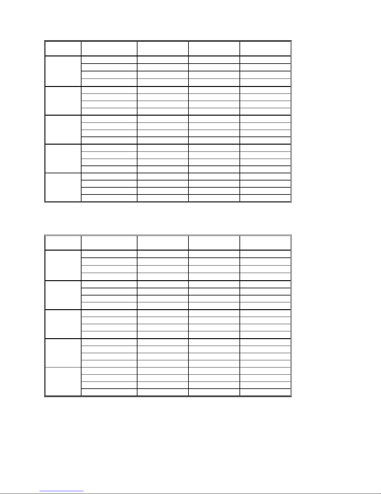
SM2060 and SM2064 7½ Digit DMM’s feature table:
Function SM/SMX2060
DMM
DCV five ranges 240mV to 330V
ACV five ranges 240mV to 330V
2-Wire Ohms, six ranges 240 Ω to 24 MΩ √ √
4-Wire Ohms, six ranges 240 Ω to 24 MΩ √ √
DC current, four ranges 2.4 mA to 2.4 A
AC current, four ranges 2.4 mA to 2.4 A
Diode V/I characteristics at 100 ηA to 1mA √ √ (plus 10mA)
Auto range, Relative
Min/Max, dB and percent deviation functions
On board measurement buffer
External and threshold trigger
Thermocouples type;
High Dynamic range; +24,000,000 counts
Frequency / Period measurement
Measurement rate: 0.2 to 1,400/sec
Measurement rate: to 20,000/sec
Capacitance, ramp type, eight ranges, 1 nF to 10 mF
Capacitance, In-Circuit method five ranges, 24nF to 2.4mF
Inductance, six ranges 33 µH to 3.3 H
Internal DMM temperature sensor
Offset Ohms
Temperature types pt385, 3911, 3916, 3926, Copper, variable Ro
Pulse width, pos./neg., & duty cycle
Totalizer/event counter
Variable threshold DAC; all timing measure.
Peak to Peak, Crest factor, Median
Six wire Ohms (with force/sense)
DCV source to ±10.0 V
ACV source 0 to 20 V pk-pk, 2 Hz to 75 KHz
DC current source, 1 nA to 12.5 mA
Leakage measurement to ±10.0V three ranges 240nA, 2.4uA, 25uA
Expanded ranges
2-Wire Ohms two additional ranges 24 Ω and 240 MΩ
4-Wire Ohms additional range 24 Ω
Resistance with V&I limits (to 10GΩ)
DC Current four additional ranges 240nA, 2.4µA, 24µA, 240µA
B, E, J, K, N, R, S, T
√ √
√ √
√ √
√ √
√ √
√ √
√ √
√ √
√ √
√ √
√ √
√ √
SM/SMX2064
High Workload
DMM
√
√
√
√
√
√
√
√
√
√
√
√
√
√
√
√
√
√
√
√
√
9 Signametrics
2.0 Specifications
The following specifications are based on both, verification of large number of units as well as
mathematical evaluation. They should be considered under the environment specified.
It is important to note that a DMM specified range is expressed as a numeric value indicating the highest
absolute voltage that can be measured. The lowest value that can be detected is expressed by the
corresponding resolution for the range.
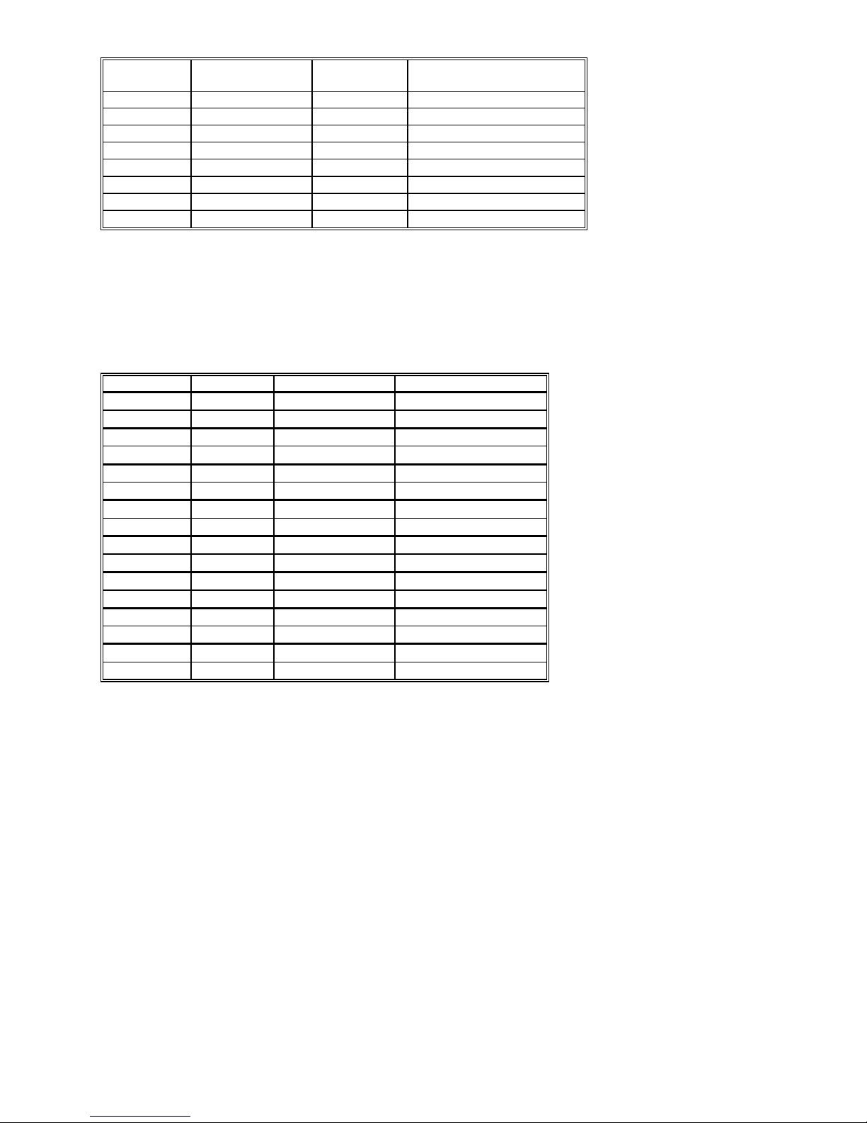
2.1 DC Voltage Measurement
Input Characteristics
• Input Resistance 240 mV, 2.4 V Ranges: >10 GΩ, with typical leakage of 50pA
• Input Resistance 24 V, 240 V, 330V Ranges: 10.00 MΩ
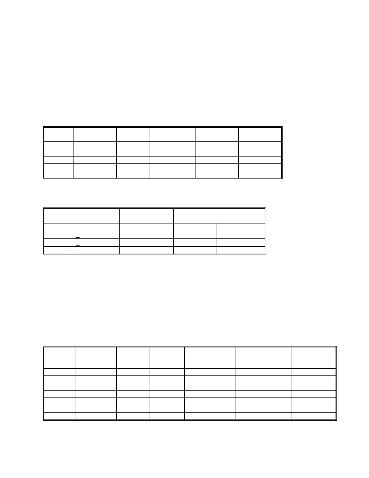
Accuracy ± (% of reading + Volts) [1]
Range Full Scale
7-½ Digits
240 mV 240.00000 mV
2.4 V 2.4000000 V
24 V 24.000000 V
240 V 240.00000 V
330 V
330.00000 V
Resolution 24 hours
23°C ± 1°C
10 ηV 0.003 + 1 µV 0.004 + 1.5 µV 0.005 + 2 µV
100 ηV 0.002 + 3 µV 0.0025 + 5 µV 0.003 + 10 µV
1 µV 0.003 + 150 µV 0.004 + 250 µV 0.005 + 300 µV
10 µV
0.004 + 200 µV 0.005 + 300 µV
10 µV
0.005 + 250 µV 0.01+ 400 µV
90 Days
23°C ± 5°C
One Year 23°C
± 5°C
0.006 + 0.5 mV
0.015 + 0.7 mV
[1] With Aperture set to 0.5 Sec, and within one hour from Self Calibration (S-Cal).
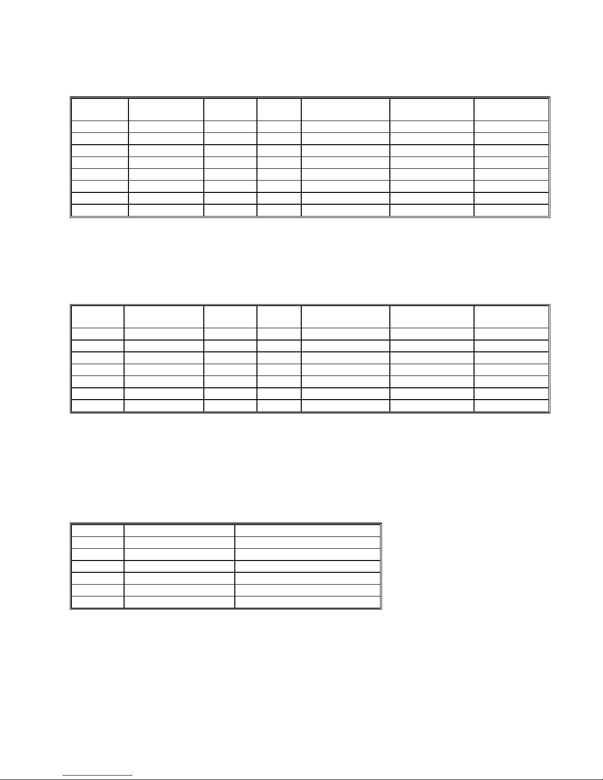
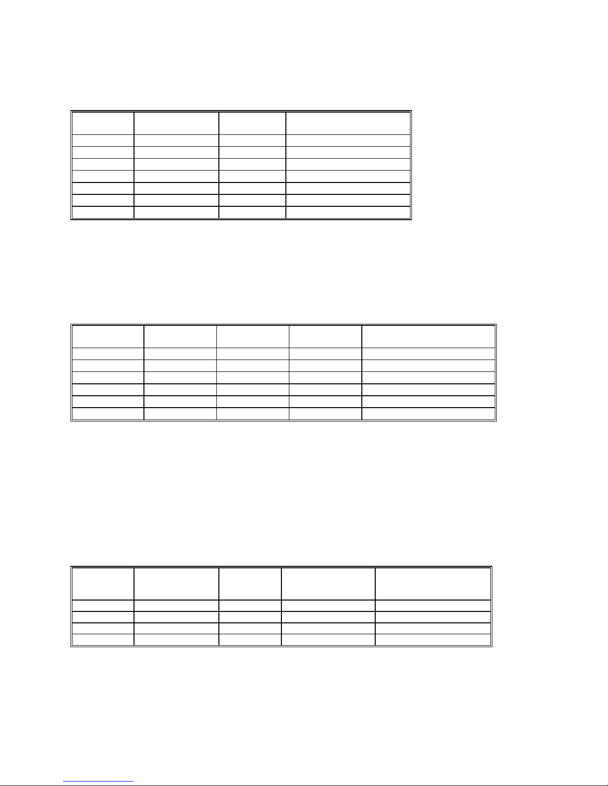
For resolution at smaller Apertures, see the following table. Use this table for DC Volts, DC current
and Resistance measurements.
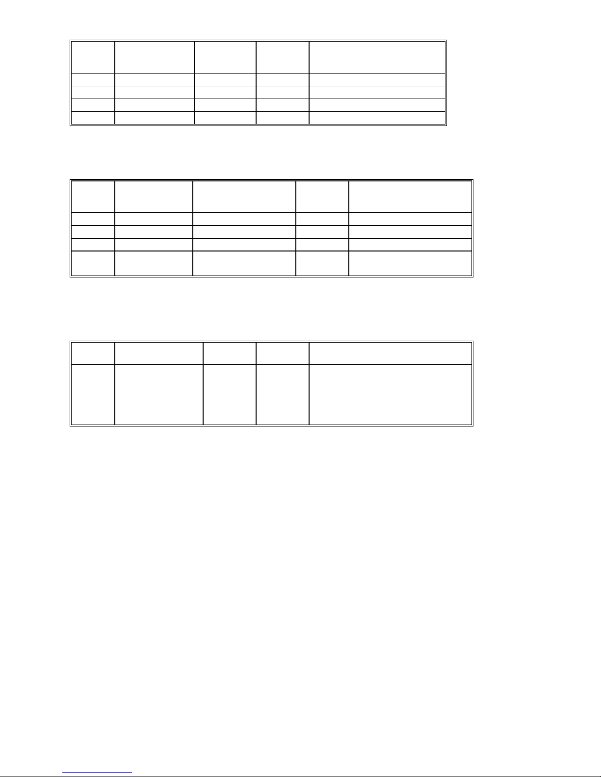
Measurement Aperture
SM2060, SM2064
Maximum reading
rate
Resolution
0.5 s < Aperture 2 / second 7-1/2 digits 25 bits
10 ms < Aperture 100 / second 6-1/2 digits 22 bits
625µs < Aperture
1200 / second 5-1/2 digits 18 bits
2.5us < Aperture [2] 20,000 / second [2] 4-1/2 digits 14 bits
[2] Available only with the SM2064.
DCV Noise Rejection Normal Mode Rejection, at 50, 60, or 400 Hz ± 0.5%, is better than 95 dB
for apertures of 0.160s and higher. Common Mode Rejection (with 1 kΩ lead imbalance) is better
than 120 dB for these conditions.
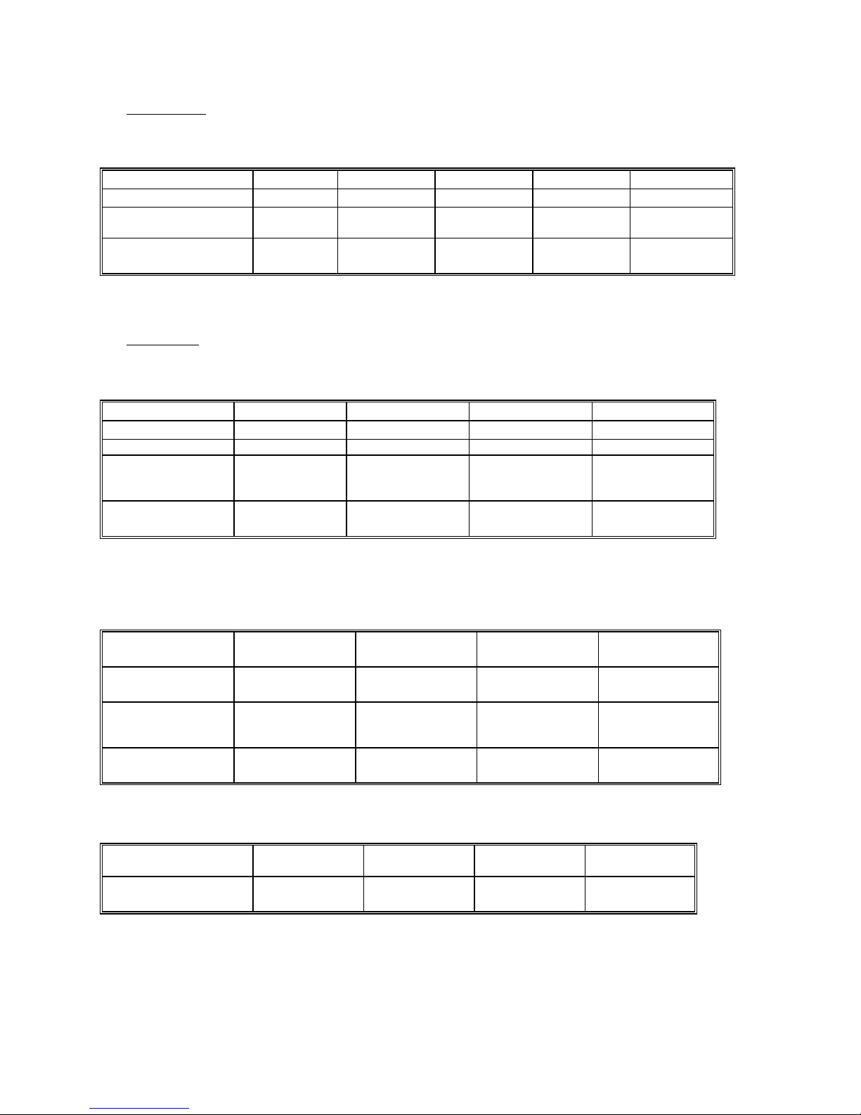
2.2 DC Current Measurement
Input Characteristics
• Number of shunts Five in SM2064, two in the SM2060
• Protected with 2.5A Fast blow fuse
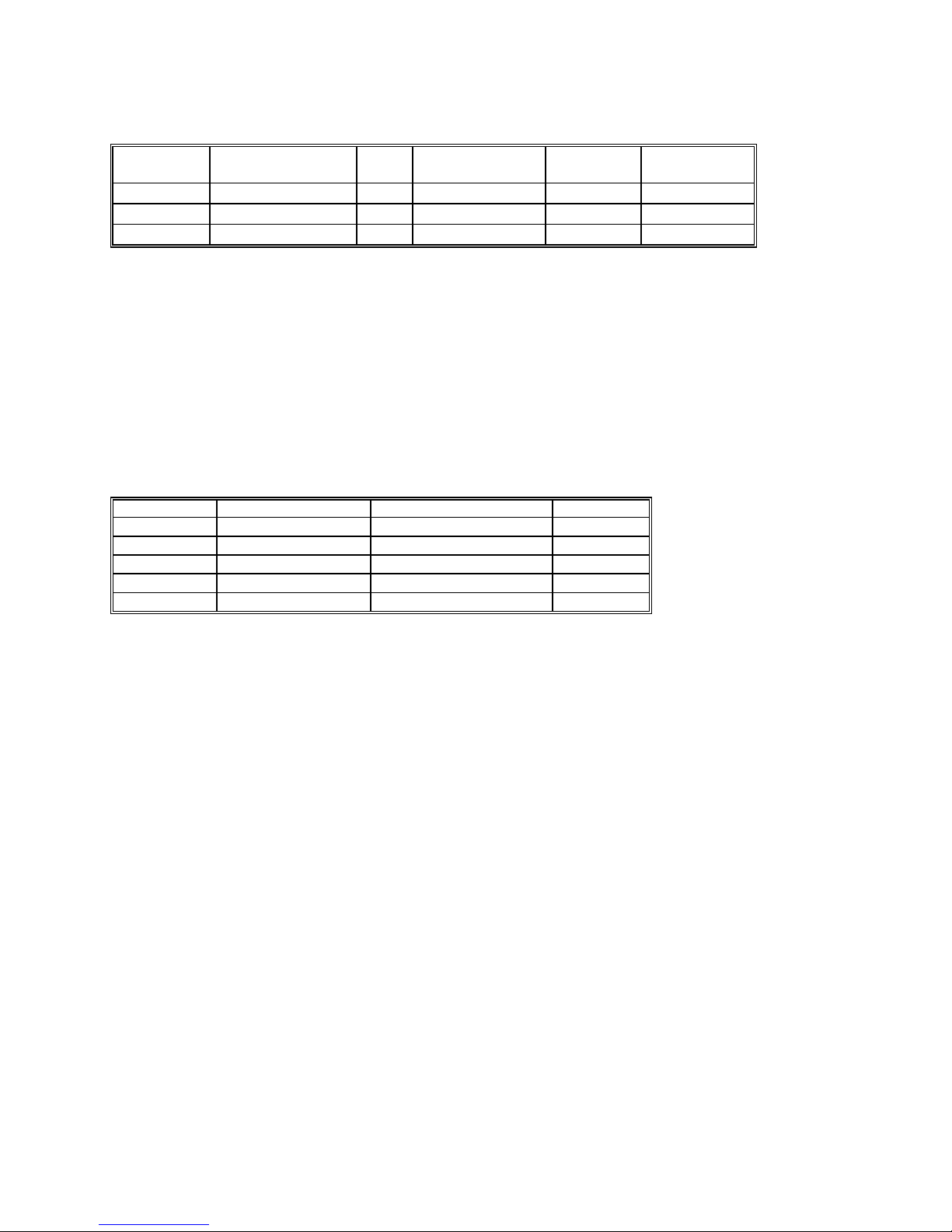
Accuracy ± (% of reading + Amps) [1]
Range Full Scale
6-½ Digits
240 ηA [2] 240.0000 ηA
2.4 µA [2] 2.400000 µA
24 µA [2] 24.00000 µA
240 µA [2] 240.000 µA 10 ηA
2.4 mA 2.40000 mA
24 mA 24.0000 mA
240 mA 240.000 mA
2.4 A 2.40000 A
Resolution Max Burden
Voltage
0.1 pA
1 pA
10 pA
10 ηA
100 ηA
1 µA
10 µA
100 µV
100 µV
100 µV
2.5mV
25mV
250mV
55mV
520mV
24 hours
23°C ± 5°C
0.07 + 40pA 0.1 + 45pA 0.17 + 60pA
0.05 + 70pA 0.08 + 90pA 0.21 + 150pA
0.05 + 400pA 0.08 + 600pA 0.13 + 0.8nA
0.052 + 200 ηA 0.07 + 300 ηA 0.1 + 400 ηA
0.05 + 300 ηA 0.06 + 400 ηA 0.07 + 550 ηA
0.05 + 350 ηA 0.065 + 450 ηA 0.08 + 550 ηA
0.05 + 50 µA 0.055 + 60 µA 0.065 + 80 µA
0.3 + 60 µA 0.4 + 70 µA 0.45 + 90 µA
90 Days
23°C ± 5°C
[1] With Aperture set to 0.96 Sec, and within one hour from Zero (Relative control).
[2] Available only with the SM2064.
One Year 23°C
± 5°C
Signametrics 10
2.3 Resistance Measurements
2.3.1 2-wire
Accuracy ± (% of reading + Ω) [1]
Range [4] Full Scale
7 ½ Digits
24 Ω[3] 24.000000 Ω 1 µΩ
240 Ω 240.00000 Ω 10 µΩ
2.4 kΩ 2.4000000 kΩ 100 µΩ
24 kΩ 24.000000 kΩ 1 mΩ 100 µA 0.0025 + 300 mΩ 0.004 + 330 mΩ 0.006 + 350 mΩ
240 kΩ 240.00000 kΩ 10 mΩ 10 µA 0.0055 + 3.2 Ω 0.006 + 4 Ω 0.007 + 5 Ω
2.4 MΩ 2.4000000 MΩ 100 mΩ 1 µA 0.018 + 40 Ω 0.03 + 50 Ω 0.04 + 70 Ω
24 MΩ 24.0000 MΩ 100 Ω
240 MΩ[3] 240.000 MΩ 1 kΩ
Resolution Source
current
10 mA
1 mA
1 mA
100 nA
10 nA
24 hours
23°C ± 1°C
0.0038 + 1.4 mΩ [2] 0.005 + 1.6 mΩ [2] 0.008 + 2 mΩ [2]
0.0037 + 4.5 mΩ [2] 0.0046 + 5 mΩ [2] 0.007 + 6 mΩ [2]
0.0023 + 28 mΩ 0.004 + 32 mΩ 0.006 + 33 mΩ
0.12 + 400 Ω 0.13 + 500 Ω 0.2 + 600 Ω
0.8 + 20 kΩ 1.0 + 30 kΩ 1.3 + 50 kΩ
90 Days
23°C ± 5°C
One Year
23°C ± 5°C
[1] With Aperture set to 0.5 Sec, and within one hour from Self Calibration (S-Cal).
[2] Use of S-Cal and Relative to improve measurement floor.
[3] Ranges are only available with the SM2064.
Ω
[4] Test voltages are 2.4V max with the exception of the 24
and 240 Ω ranges 240 mV.
2.3.2 4-wire
Accuracy ± (% of reading + Ω) [1]
Range [4] Full Scale
7 ½ Digits
24 Ω [3] 24.000000 Ω 1 µΩ
240 Ω 240.00000 Ω 10 µΩ
2.4 kΩ 2.4000000 kΩ 100 µΩ
24 kΩ 24.000000 kΩ 1 mΩ 100 µA 0.0025 + 300 mΩ 0.004 + 330 mΩ 0.006 + 350 mΩ
240 kΩ 240.00000 kΩ 10 mΩ 10 µA 0.0055 + 3.2 Ω 0.007 + 4 Ω 0.007 + 5 Ω
2.4 MΩ 2.4000000 MΩ 100 mΩ 1 µA 0.018 + 40 Ω 0.03 + 50 Ω 0.04 + 70 Ω
24 MΩ 24.0000 MΩ 100 Ω
Resolution Source
current
10 mA
1 mA
1 mA
100 nA
24 hours
23°C ± 1°C
0.0038 + 0.7 mΩ [2] 0.005 + 0.8 mΩ [2] 0.008 + 1 mΩ [2]
0.0037 + 3 mΩ [2] 0.0046 + 4 mΩ [2] 0.007 + 5 mΩ [2]
0.0023 + 28 mΩ 0.004 + 32 mΩ 0.006 + 33 mΩ
0.12 + 400 Ω 0.13 + 500 Ω 0.2 + 600 Ω
90 Days
23°C ± 5°C
One Year
23°C ± 5°C
[1] With Aperture set to 0.5 Sec, and within one hour from Self Calibration (S-Cal).
[2] Use of Relative to facilitate indicated floor (adder part of spec).
[3] 24 Ω range only available with SM2064.
Ω
[4] Test voltages are 2.4V max with the exception of the 24
and 240 Ω ranges 240 mV.
2.3.3 6-wire Guarded Resistance Measurement (SM2064)
This is an in-circuit forced guard measurement method, as implemented in ICT testers. Add this typical additional
error to the above specification.
Range Guard forced current
24 Ω [3]
240 Ω
2.4 kΩ
24 kΩ 100 µA 0.03 + 1 Ω
240 kΩ 10 µA 0.35 + 10 Ω
24 MΩ 1 µA 0.85 + 1000 Ω
[1] This table should be used in conjunction with the 2-wire and 4-wire table above.
10 mA
1 mA
1 mA
Accuracy ± (% of reading + Ω)
One Year 23°C ± 5°C [1]
0.3 + 4 mΩ
0.003 + 20 mΩ
0.005 + 100 mΩ
11 Signametrics
2.3.4 Extended Resistance Measurements (SM2064)
Characteristics
• Test Voltage Adjustable between -10V and +10V in 5mV steps
Accuracy ± (% of reading + Amps) [1]
Range
400kΩ
4MΩ
40MΩ
Measurement range
1kΩ to 100MΩ
10kΩ to 1GΩ
100kΩ to 10GΩ
Resol
ution
10Ω
100Ω
1kΩ
Current Limit [3] 90 Days
25µA
2.5µA
250nA
23°C ± 5°C
0.2 +
50Ω
0.3 +
350Ω
0.4 +
3kΩ
One Year 23°C
± 5°C
0.33 + 90Ω
0.43 +
0.55 + 4.5kΩ
550Ω
[1] With Aperture set to 0.5 Sec, and within one hour from Zero (Relative control).
[2] Multiply “% of reading” by 1/Voltage Source for applied voltages below 1V
[3] Limit is reached when the test current exceeds the Current Limit, or it is below 0.04% of
this value.
2.4 AC Voltage Measurements
Input Characteristics
• Input Resistance 1 MΩ, shunted by < 300 pF, all ranges
• Max. Crest Factor 4 at Full Scale, increasing to 7 at Lowest Specified Voltage
• AC coupled Specified range: 10 Hz to 100 kHz
• Typical Settling time < 0.5 sec to within 0.1% of final value
• Typical Settling time Fast RMS < 0.05 sec to within 0.1% of final value
2.4.1 AC Voltage True RMS Measurement
Range Full Scale 7-½ Digits Lowest specified Voltage Resolution
240 mV 240.0000 mV 5 mV [1]
2.4 V 2.400000 V 10 mV
24 V 24.00000 V 100 mV
240 V 240.0000 V 1 V
330 V
[1] Between 5 mV and 10 mV, add 100 µV additional errors to the accuracy table below.
[2] Signal is limited to 8x10
32 kHz, or 8x10
6
330.0000 V 2 V
6
Volt Hz Product. For example, the largest frequency input at 250 V is
Volt x Hz.
100 ηV
1 µV
10 µV
100 µV
100 µV
Signametrics 12
AC Volts Accuracy with Fast RMS disabled (default).
With Fast RMS disabled, settling time to rated accuracy is within 0.5 s.
Accuracy ± (% of reading + Volts) [1]
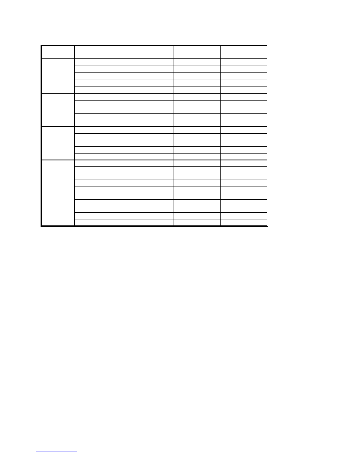
Range Frequency 24 hours
23°C ± 1°C
240 mV
2.4 V
24 V
240 V
330 V
10 Hz - 20 Hz
20 Hz - 47 Hz
47 Hz - 10 kHz
10 kHz - 50 kHz
50 kHz - 100 kHz
10 Hz - 20 Hz 3.0 + 2 mV 3.1 + 2.2 mV 3.2 + 2.5 mV
20 Hz - 47 Hz 0.93 + 1.3 mV 0.96 + 1.5 mV 1.0 + 1.7 mV
47 Hz - 10 kHz 0.05 + 1 mV 0.055 + 1.1 mV 0.065 + 1.2 mV
10 kHz - 50 kHz 0.62 + 1.2 mV 0.65 + 1.3 mV 0.70 + 1.5 mV
50 kHz - 100 kHz 5.1 + 1.5 mV 5.2 + 1.7 mV 5.3 + 2 mV
10 Hz - 20 Hz 3.0 + 14 mV 3.1 + 16 mV 3.3 + 20 mV
20 Hz - 47 Hz 0.93 + 12 mV 0.96 + 14 mV 1.0 + 16 mV
47 Hz - 10 kHz 0.06 + 10 mV 0.065 + 11 mV 0.073 + 13 mV
10 kHz - 50 kHz 0.31 + 18 mV 0.33 + 21 mV 0.35 + 25 mV
50 kHz - 100 kHz 2.0 + 30 mV 2.2 + 35 mV 2.4 + 40 mV
10 Hz - 20 Hz 3.0 + 140 mV 3.1 + 160 mV 3.3 + 200 mV
20 Hz - 47 Hz 0.93 + 120 mV 0.96 + 130 mV 1.0 + 150 mV
47 Hz - 10 kHz 0.04 + 100 mV 0.045 + 110 mV 0.06 + 130 mV
10 kHz - 50 kHz 0.32 + 150 mV 0.4 + 170 mV 0.45 + 200 mV
50 kHz - 100 kHz 2.5 + 200 mV 2.8 + 240 mV 3.2 + 300 mV
10 Hz - 20 Hz 3.0 + 200 mV 3.1 + 160 mV 3.3 + 200 mV
20 Hz - 47 Hz 1.0 + 180 mV 1.1 + 200 mV 1.1 + 250 mV
47 Hz - 10 kHz 0.05 + 150 mV 0.07 + 200 mV 0.08 + 230 mV
10 kHz - 50 kHz 0.34 + 200 mV 0.45 + 250 mV 0.5 + 300 mV
50 kHz - 100 kHz 2.5 + 270 mV 2.8 + 350 mV 3.2 + 400 mV
3.0 + 350 µV 3.1 + 380 µV 3.2 + 430 µV
0.92 + 150 µV 0.93 + 170 µV 0.95 + 200 µV
0.13 + 100 µV 0.14 + 110 µV 0.15 + 120 µV
0.55 + 160 µV 0.6 + 200 µV 0.63 + 230 µV
5.3 + 350 µV 5.4 + 370 µV 5.6 + 400 µV
90 Days
23°C ± 5°C
One Year
23°C ± 5°C
ACV Noise Rejection Common Mode rejection, for 50 Hz or 60 Hz with 1 kΩ imbalance in either lead, is better
than 60 dB.
AC Volts Accuracy with Fast RMS enabled.
13 Signametrics
Fast RMS settles to rated accuracy within 50ms.
Accuracy ± (% of reading + Volts) [1]
Range Frequency 24 hours
23°C ± 1°C
240 mV
2.4 V
24 V
240 V
330 V
350 Hz - 800 Hz
800 Hz - 10 kHz
10 kHz - 50 kHz
50 kHz - 100 kHz
350 Hz - 800 Hz 0.93 + 1.3 mV 0.96 + 1.5 mV 1.0 + 1.7 mV
800 Hz - 10 kHz 0.068 + 1 mV 0.075 + 1.1 mV 0.08 + 1.2 mV
10 kHz - 50 kHz 0.62 + 1.2 mV 0.65 + 1.3 mV 0.70 + 1.5 mV
50 kHz - 100 kHz 5.1 + 1.5 mV 5.2 + 1.7 mV 5.3 + 2 mV
350 Hz - 800 Hz 0.93 + 12 mV 0.96 + 14 mV 1.0 + 16 mV
800 Hz - 10 kHz 0.065 + 10 mV 0.068 + 11 mV 0.073 + 13 mV
10 kHz - 50 kHz 0.31 + 18 mV 0.33 + 21 mV 0.35 + 25 mV
50 kHz - 100 kHz 2.0 + 30 mV 2.2 + 35 mV 2.4 + 40 mV
350 Hz - 800 Hz 0.93 + 120 mV 0.96 + 130 mV 1.0 + 150 mV
800 Hz - 10 kHz 0.062 + 100 mV 0.065 + 110 mV 0.08 + 130 mV
10 kHz - 50 kHz 0.32 + 150 mV 0.4 + 170 mV 0.45 + 200 mV
50 kHz - 100 kHz 2.5 + 200 mV 2.8 + 240 mV 3.2 + 300 mV
350 Hz - 800 Hz 1.0 + 180 mV 1.1 + 200 mV 1.1 + 250 mV
800 Hz - 10 kHz 0.065 + 150 mV 0.07 + 200 mV 0.08 + 230 mV
10 kHz - 50 kHz 0.34 + 200 mV 0.45 + 250 mV 0.5 + 300 mV
50 kHz - 100 kHz 2.5 + 270 mV 2.8 + 350 mV 3.2 + 400 mV
0.6 + 150 µV 0.65 + 170 µV 0.7 + 200 µV
0.13 + 100 µV 0.14 + 110 µV 0.15 + 120 µV
0.55 + 160 µV 0.6 + 200 µV 0.63 + 230 µV
5.3 + 350 µV 5.4 + 370 µV 5.6 + 400 µV
90 Days
23°C ± 5°C
One Year
23°C ± 5°C
AC Volts Accuracy with Slow RMS (default).
Settles to rated accuracy within 1X to 10X signal period, settable by user.
Range Frequency 24 hours
23°C ± 1°C
240 mV
2.4 V
24 V
240 V
330 V
0.5 Hz - 10 Hz
10 Hz - 20 Hz
20 Hz - 60 Hz
60 kHz - 200 Hz
0.5 Hz - 10 Hz 0.2 + 2 mV 0.25 + 2.2 mV 0.3 + 2.5 mV
10 Hz - 20 Hz 0.3 + 1.3 mV 0.35 + 1.5 mV 1.0 + 1.7 mV
20 Hz - 60 Hz 0.5 + 1 mV 0.55 + 1.1 mV 0.65 + 1.2 mV
60 kHz - 200 Hz 0.62 + 1.2 mV 0.65 + 1.3 mV 0.70 + 1.5 mV
0.5 Hz - 10 Hz 3.0 + 14 mV 3.1 + 16 mV 3.3 + 20 mV
10 Hz - 20 Hz 0.93 + 12 mV 0.96 + 14 mV 1.0 + 16 mV
20 Hz - 60 Hz 0.06 + 10 mV 0.065 + 11 mV 0.073 + 13 mV
60 kHz - 200 Hz 0.31 + 18 mV 0.33 + 21 mV 0.35 + 25 mV
0.5 Hz - 10 Hz 3.0 + 140 mV 3.1 + 160 mV 3.3 + 200 mV
10 Hz - 20 Hz 0.93 + 120 mV 0.96 + 130 mV 1.0 + 150 mV
20 Hz - 60 Hz 0.04 + 100 mV 0.045 + 110 mV 0.06 + 130 mV
60 kHz - 200 Hz 0.32 + 150 mV 0.4 + 170 mV 0.45 + 200 mV
0.5 Hz - 10 Hz 3.0 + 200 mV 3.1 + 160 mV 3.3 + 200 mV
10 Hz - 20 Hz 1.0 + 180 mV 1.1 + 200 mV 1.1 + 250 mV
20 Hz - 60 Hz 0.05 + 150 mV 0.07 + 200 mV 0.08 + 230 mV
60 kHz - 200 Hz 0.34 + 200 mV 0.45 + 250 mV 0.5 + 300 mV
0.25 + 100 µV 0.3 + 200 µV 0.35 + 300 µV
0.3 + 150 µV 0.35 + 170 µV 0.4 + 200 µV
0.13 + 100 µV 0.14 + 110 µV 0.15 + 120 µV
0.55 + 160 µV 0.6 + 200 µV 0.63 + 230 µV
2.4.2 AC Peak-to-Peak Measurement (SM2064)
• Measures the peak-to-peak value of a repetitive waveform.
Signametrics 14
90 Days
23°C ± 5°C
One Year
23°C ± 5°C
ACV
Range
240 mV 0.1 V 1.9 V 1 mV
2.4 V 1.0 V 16 V 10 mV 0.5 ± 40 mV
24 V 10 V 190 V 100 mV 0.5 ± 700 mV
240 V 100 V 850 V 1 V 0.55 ± 6 V
[1] Signal frequency range 30 Hz to 60 kHz.
2.4.3 AC Crest Factor Measurement (SM2064)
•
Measures the crest factor (CF) of a repetitive waveform
Lowest specified
input voltage
(Vp-p)
Full Scale
reading (Vp-p)
Resolution
Typical Accuracy 23°C ± 5°C
One Year [1]
0.5 ± 3 mV
ACV
Range
240 mV 0.1 V 1.9 V 0.01
2.4 V 1.0 V 16 V 0.01 2.1 ±0.1
24 V 10 V 190 V 0.01 2.0 ±0.1
240 V 100 V 700 V 0.01 2.0 ±0.1
330 V 100 V 850 V 0.01 2.0 ±0.1
[1] Crest factor measurement requires signal frequency of 30 Hz to 60 kHz.
2.4.4 AC Median Value Measurement (SM2064)
• Measures the mid-point between the positive and negative peaks of a repetitive waveform
• Used to determine the Threshold DAC setting for optimal frequency and timing measurements
ACV
Range
240 mV 0.08 V
2.4 V 0.80 V
24 V 8 V
240 V 80 V
330 V 80 V
[1] Median measurements require a repetitive signal with frequency range of 30 Hz to 30 KHz.
Lowest specified
input voltage
(Vp-p)
Lowest specified input
voltage (Vp-p)
Highest specified input
voltages (Vp-p)
Full Scale
reading
±0.95 V
±9.5 V
±95.0 V
±350.0 V
±350.0 V
Resolution
1 mV
10 mV 3% ±160 mV
100 mV 3% ±1.4 V
1 V 3% ±12 V
1 V 3% ±12 V
Resolution
Typical Accuracy 23°C ± 5°C
One Year [1]
2.2 ±0.3
Typical Accuracy 23°C ± 5°C One Year [1]
2.0% ±17 mV
2.5 AC Current Measurement, True RMS
15 Signametrics
Input Characteristics
• Crest Factor 4 at Full Scale, increasing to 10 at Lowest Specified Current
• Protected with 2.5 A
Fast Blow fuse
Range Full Scale 6 1/2 Digits Lowest Specified
Current
2.4 mA 2.400000 mA
24 mA 24.00000 mA
240 mA 240.0000 mA 3 mA 55mV 100 nA
2.4 A 2.400000 A 30 mA 520mV 1 uA
60 µA
300 µA
Accuracy ± (% of reading + Amps)
Range Frequency [1] 24 hours
23°C ± 1°C
2.4 mA
24 mA
240 mA
2.4 A
10 Hz - 20 Hz
20 Hz - 47 Hz
47 Hz - 1 kHz
1 kHz - 10 kHz
10 Hz - 20 Hz
20 Hz - 47 Hz
47 Hz - 1 kHz
1 kHz - 10 kHz
10 Hz - 20 Hz
20 Hz - 47 Hz
47 Hz - 1 kHz
1 kHz - 10 kHz
10 Hz - 20 Hz 1.8 + 4 mA 2.5 + 4.5 mA 2.7 + 5 mA
20 Hz - 47 Hz 0.66 + 4 mA 0.8 + 6 mA 0.9 + 6 mA
47 Hz - 1 kHz 0.3 + 3.8mA 0.33 + 3.8 mA 0.35 + 4 mA
1 kHz - 10 kHz 0.4 + 4mA 0.45 + 4.5 mA 0.5 + 5 mA
3.8 + 4 µA 2.7 + 4 µA 2.9 + 4 µA
0.9 + 4 µA 0.9 + 4 µA 1.0 + 4 µA
0.04 + 1.5 µA 0.08 + 3 µA 0.12 + 4 µA
0.12 + 4 µA 0.14 + 4 µA 0.22 + 4 µA
1.8 + 30 µA 2.6 + 30 µA 2.8 + 30 µA
0.6 + 30 µA 0.9 + 30 µA 1.0 + 30 µA
0.07 + 10 µA 0.15 + 20 µA 0.16 + 30 µA
0.21 + 30 µA 0.3 + 40 µA 0.4 + 40 µA
1.8 + 400 µA 2.7 + 400 µA 2.8 + 400 µA
0.6 + 400 µA 0.9 + 400 µA 1.0 + 400 µA
0.1 + 100 µA 0.17 + 180 µA 0.2 + 220 µA
0.3 + 300 µA 0.35 + 350 µA 0.4 + 400 µA
[1] All AC Current ranges have typical measurement capability of at least 20 kHz.
Maximum Burden
Voltage (RMS)
25mV 1 nA
250mV 10 nA
Resolution
90 Days
23°C ± 10°C
One Year
23°C ± 10°C
2.6 Leakage Measurement (SM2064)
Characteristics
µ
• Burden Voltage: < 100
• Test Voltage: Adjustable between -10V to +10V in 5mV steps
Accuracy ± (% of reading + Amps) [1]
Range Full Scale
6-½ Digits
240 ηA 240.0000 ηA
2.4 µA 2.400000 µA
24 µA 24.00000 µA
[1] With Aperture set to 0.5 Sec, and within one hour from Zero (Relative control).
V
Resolution 24 hours
23°C ± 5°C
0.1 pA 0.15 + 50pA 0.2 + 65pA 0.17 + 100pA
1 pA 0.1 + 350pA 0.15 + 500pA 0.2 + 600pA
10 pA 0.08 + 3nA 0.12 + 4nA 0.18 + 2nA
90 Days
23°C ± 5°C
One Year 23°C
± 5°C
2.7 RTD Temperature Measurement (SM2064)
Signametrics 16
• Ro: Variable from 10
Ω
to 10 kΩ
• Measurement Method: 4-Wire
• Temperature units: Selectable
o
C or oF
RTD Type
pt385, pt3911,
pt3916, pt3926
pt385, pt3911,
pt3916, pt3926
Cu (Copper)
Cu (Copper)
Ro (Ω)
100, 200 Ω 0.01°C -150 to 650°C ±0.06°C
500, 1 kΩ 0.01°C -150 to 650°C ±0.03°C
Less than 12 Ω 0.01°C -100 to 200°C ±0.18°C for temperatures ≤ 20°C, ±0.05°C
Higher than 90 Ω 0.01°C -100 to 200°C ±0.10°C for temperatures ≤ 20°C, ±0.05°C
[1] With Aperture of 0.5s and higher, using a 4-wire RTD. Measurement accuracy does not include
RTD probe error.
Resolution Temperature
range
Temperature Accuracy 23°C ± 5°C [1]
One Year
otherwise
otherwise
2.8 Thermocouple Temperature Measurement (SM2064)
• Cold Junction Compensation: By Sensor measurement or S/W setting.
• Cold Junction Temperature range: 0
o
C
• Cold Junction Sensor: Use SMX40T or SM40T Isothermal unit, or define sensor equation
to 50
o
C
• Isothermal Block compatibility: SM4022, SM4042, SMX4032, SM40T, SMX40T
• Temperature units: Selectable
o
C or oF
TC Type Resolution Maximum Temperature
[2]
B
E
J
K
N
R
S
T
0.01°C 2200°C ±0.38 °C
0.01°C 1200°C ±0.035 °C
0.01°C 2000°C ±0.06 °C
0.01°C 3000°C ±0.07 °C
0.01°C 3000°C ±0.10 °C
0.01°C 2700°C ±0.25 °C
0.01°C 3500°C ±0.35 °C
0.01°C 550°C ±0.06 °C
[1] With Aperture of 0.5s and higher. Measurement accuracy does not include Thermocouple error.
[2] DMM Linearization temperature range may be greater than that of the Thermocouple device.
Temperature Accuracy 23°C ± 5°C [1]
One Year
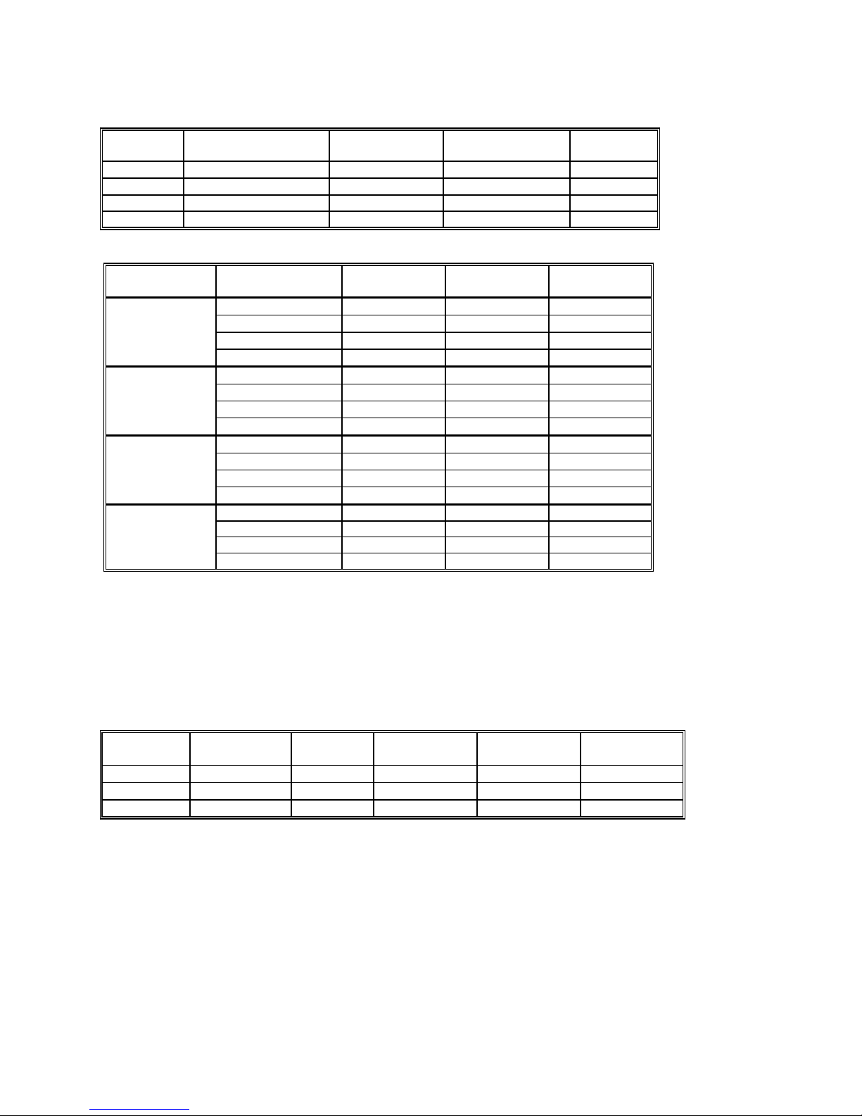
2.9 Additional Component Measurement Capability
2.9.1 Diode Characterization
• Available DC current values 100 ηA, 1 µA, 10 µA, 100 µA and 1 mA.
• SM2064 add variable current of 10 ηA to 12.5 mA
• Typical Current Value Uncertainty 1%
• Typical Voltage Value Uncertainty 0.02%
•
Maximum diode voltage compliance 4 V
2.9.2 Capacitance, Ramp Method (SM2064)
Accuracy ± (% of reading + Farads) [1]
17 Signametrics
Range Full Scale
Reading
1,200 pF 1,199.9 pF 0.1 pF 1.5 ± 0.25 pF
12 ηF 11.999 ηF
120 ηF 119.99 ηF
1.2 µF 1.1999 µF
12 µF 11.999 µF 1 ηF
120 µF 119.99 µF 10 ηF
1.2 mF 1.1999 mF
12 mF 50.000 mF
Resolution One Year
23°C ± 5°C
1 pF 1.2 ± 5 pF
10 pF 1.0
100 pF 1.0
100 ηF
1 µF
1.0
1.0
1.2
2
[1] Within one hour of zero, using Relative control. Accuracy is specified for values higher than 5% of the selected
range with the exception of the 1,200 pF range.
This Measurement is independent of set Aperture and Read Interval. If desired, the DMMSetCapsAveSamp()
function may be used to control measurement parameters. It is provided
the application, trading off accuracy for speed.
Measurement time will vary as function of the set parameters, selected range and measured capacitance. The following are
measurement times associated with the default parameters, as range is selected.
Range Input Measurement Time Measurement Rate (rps)
1,200 pF 5% of Scale
1,200 pF Full Scale
12 ηF
12 ηF
120 ηF
120 ηF
1.2 µF
1.2 µF
12 µF
12 µF
120 µF
120 µF
1.2 mF 5% of Scale
1.2 mF Full Scale
12 mF 5% of Scale
12 mF Full Scale
5% of Scale
Full Scale
5% of Scale
Full Scale
5% of Scale
Full Scale
5% of Scale
Full Scale
5% of Scale
Full Scale
19.5 ms 51.3
52.3 ms 19.1
70.0 ms 14.3
118ms 8.5
8.9 ms 112.4
127 ms 7.9
15.6 ms 64.1
175 ms 5.7
14.1 ms 70.9
480 ms 2.1
17.3 ms 57.8
50.3 ms 19.9
52.6 ms 19.0
151.5 ms 6.6
52.8 ms 18.9
170 ms 5.9
means to fine tune the measurement timing for
Signametrics 18
2.9.3 Capacitance, In-Circuit Method (SM2064)
• Adjustable Peak Voltages Stimulus 100mV to 1.3V
• Minimum Parallel Load Resistance 100Ω
Accuracy ± (% of reading + Farads) [1]
Range Full Scale
3-½ Digits
24 ηF 23.99 ηF
240 ηF 239.9 ηF
2.4 µF 2.399 µF
24 µF 23.99 µF 10 ηF
240 µF 239.9 µF 100 ηF
2.4 mF 2.399 mF
24 mF 23.99 mF
Resolution One Year
23°C ± 5°C [2]
10 pF 2.7 ± 100 pF
100 pF 2.5 ± 500 pF
1000 pF
1 µF
10 µF
2.5 ± 5 ηF
[1] Within one hour of zero, using Relative control, and Caps Open-Cal operation
η
[2] Accuracy is specified for values higher than 5% of the selected range with the exception of the 2.4
F range.
Capacitance Measurement time is independent of set Aperture and Read Interval. It depends on range, and
capacitance
.
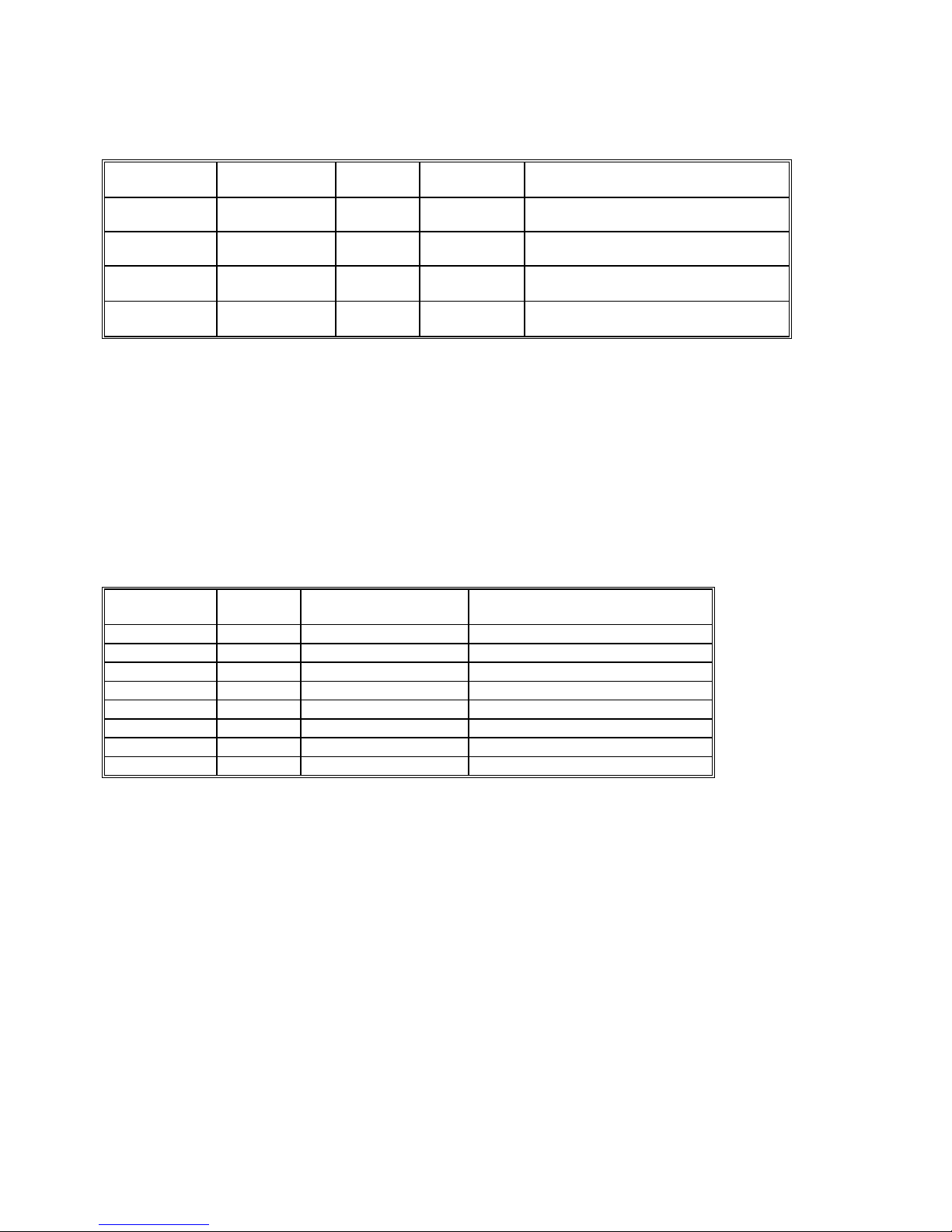
2.9.4 Inductance Measurement (SM2064)
Range Test frequency Full Scale
4 ½ Digits
24 µH
240 µH
2.4 mH 4 kHz 3.3000 mH
24 mH 1.5 kHz 33.000 mH
240 mH 1 kHz 330.00 mH
2.4 H 100 Hz 3.3000 H
75 kHz
50 kHz
33.000 µH 1 ηH 3.0% + 500 ηH
330.00 µH 10 ηH 2.0% + 3 µH
[1] Within one hour of zero, and Open Terminal Calibration.
[2] Accuracy is specified for values greater than 5% of the selected range.
Resolution
100 ηH 1.5% + 25 µH
1 µH 1.5% + 200 µH
10 µH
100 µH
Accuracy 23°C ± 5°C
One Year [2]
2.5 + 3 mH
3 + 35 mH
2.10 Time Measurements
2.10.1 Threshold DAC
• The Threshold DAC is used for selecting a detection level, providing optimal frequency and
timing measurements even at extreme duty cycle values.
± (% of setting + volts)
Selected VAC
range [1]
240 mV -1.0 V to +1.0 V 0.5 mV 1.900 V 0.2% + 4 mV
2.4 V -10.0 V to +10.0 V 5.0 mV 19.00 V 0.2% + 40 mV
24 V -100.0 V to 100.0 V 50 mV 190.0 V 0.2% + 0.4 V
240 V -400 V to 400 V 500 V 850.0 V 0.2% + 4 V
[1] This table should be used in conjunction with the AC volts section above.
Threshold range (DC
level)
Threshold
DAC
resolution
Highest allowed input
Vp-p
Typical one year setting
uncertainty
19 Signametrics
2.10.2 Frequency and Period Measurement
ACV Mode
•
Input Impedance 1 MΩ with < 300 pF
Frequency Range 2 Hz - 100 Hz 100 Hz-1 kHz 1 kHz-10 kHz 10 kHz-100 kHz 100 kHz-300 kHz
Resolution 1 mHz 10 mHz 100 mHz 1 Hz 1 Hz
Uncertainty is ±0.002% of
reading ± adder shown
Input Signal Range [1] 10% - 200%
[
1] Input RMS voltage required for a valid reading. Do not exceed 250 V RMS input. For example, 10% -200%
4 mHz 20 mHz 200 mHz 2 Hz 5 Hz
of range
of range indicates that in the 240 mVAC range, the input voltage should be 24 mV to 660 mV RMS.
ACI Mode
•
Input Impedance 10 Ω in the 3 mA and 30 mA ranges, 0.1 Ω in the 330 mA and 2.5 A ranges.
Frequency Range 2 Hz - 100 Hz 100 Hz-1 kHz 1 kHz-10 kHz 10 kHz-500 kHz
Resolution 1 mHz 10 mHz 100 mHz 1 Hz
Uncertainty 0.01% ±4 mHz 0.01% ±20 mHz 0.01% ±200 mHz 0.01% ±2 Hz
Input Signal Range,
2.4 mA, 240mA Ranges
[1]
Input Signal Range,
24 mA, 2.4 A ranges
10% -500%
of range
50% -100%
of range
10% - 200%
of range
10% - 500%
of range
50% - 100%
of range
10% -200%
of range
10% -500%
50% - 100%
of range
of range
10% - 200%
of range
45% -200%
of range
10% - 500%
of range
50% - 100%
of range
[1] Input current required to give a valid reading. For example, 10% -500% of range indicates that in the 3.3 mA
range, the input current should be 0.33 mA to 16.5 mA.
2.10.3 Duty Cycle Measurement
Frequency Range 2 Hz to 100 Hz 100 Hz to 1 kHz 1 kHz to 10 kHz 10 kHz to 100 kHz
Resolution 0.02% 0.2% 2% 20%
Typical Uncertainty is
±0.03% of reading ±
adder shown
Full scale reading 100.00 % 100.00 % 100.00 % 100.00 %
0.03% 0.3% 3% 20%
2.10.4 Pulse Width
Polarity Frequency range Resolution Width range Typical
Positive or negative pulse
widths
2 Hz to 100 kHz
1 µs 2 µs to 1 s 0.01 +/- 4 µs
± (% of reading + sec)
Uncertainty
Signametrics 20
2.10.5 Totalizer
(s)
• Active edge polarity: Positive or negative transition
• Maximum count: 10^9
•
Allowed rate: 1 to 30,000 events per second
Uses Threshold DAC
•
2.11 Trigger Functions
2.11.1 External Hardware Trigger (at DIN-7 connector)
Trigger Input voltage level range +3 V to +15 V activates the trigger.
Trigger Pulse Width
Minimum trigger input current 1 mA
Internal Reading Buffer Circular; 80 or 120 readings depending on resolution.
Isolation of trigger input ±50 V from analog DMM inputs, and from chassis
Minimum = 1/Aperture + 50µS
earth ground.
2.11.2 Analog Threshold Trigger
• Trigger point: Selectable positive or negative transition of set threshold.
• Buffer type: Circular
• Captures up to 120 post-trigger readings for apertures
• Captures up to 80 post-trigger readings for apertures > 625uSec.
•
Aperture range: 160ms to 625
•
Read Interval
• User selects number of post-trigger readings.
• The number of pre-trigger readings: buffer size – post-trigger count.
• The number of cycles the circular filled, and the trigger point are retrievable.
range
: 1/Aperture to 65ms
µS (to 2.5µS with SM2064)
< 625uSec.
2.11.3 Delayed Hardware Trigger
This function allows time for the signal to settle after a trigger has occurred.
It allows readings to be delayed up to 65mSec with 1
It allows readings to be delayed up to 1s with 2
µs resolutions.
µSec resolution
.
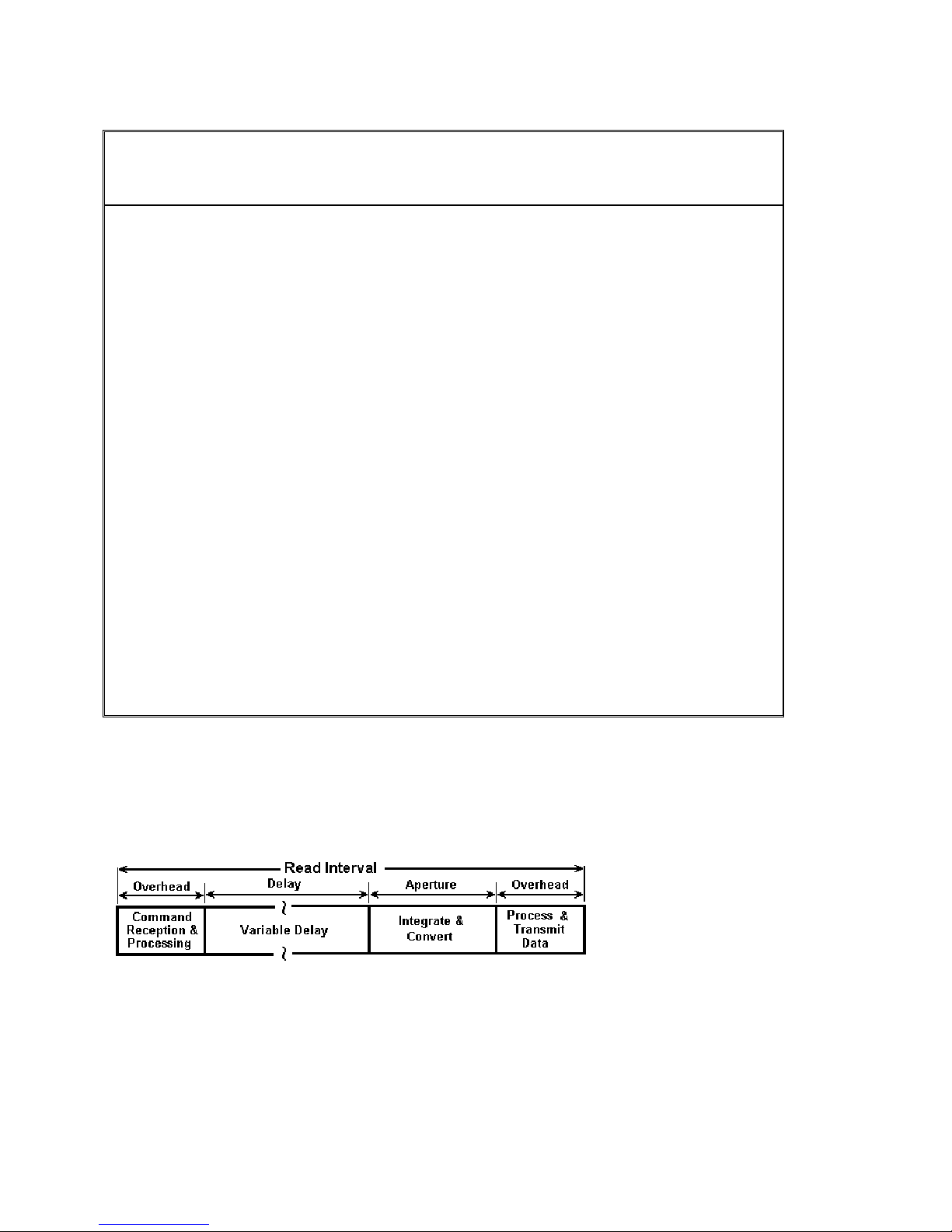
2.12 Measurement Aperture and Read Interval
Both Aperture and The Read Interval may be set. The range of values depend on the DMM model and its
mode of operation. For example, when using the internal buffer such as in External Trigger mode, the
Read Interval can be set smaller than in Command/Response operation. The time involved in processing
the measurement command and the post processing and transmission of the measurement results
constitute an overhead, which limits the minimum Read Interval to a value that is greater than the
Aperture. Setting it to zero (default) results in the fastest measurement rates at the selected Aperture. The
faster SM2064 has lower overhead and therefore a shorter minimum Read Interval than the SM2060. For
instance, with Aperture set to 625us and Read Interval set to zero, in command/response operation the
SM2060 measurement rate is about 1,090/s while that of the SM2064 is 1,370/s. This indicates overhead
of about 300µs for the SM2060 and 100µs for the SM2064.
The SM2064 has 31 A/D apertures available, ranging from 5 Seconds to 2.5µS
available measurement apertures and the corresponding minimum read intervals and measurement rates.
Power Line Rejection Command/Response
mode min. Read
21 Signametrics
. The following table contains all
H/W Trigger mode min. Read
Interval
/ max meas. Rate

Interval(s) / max meas.
(Hz)
rate(Hz)
Aperture 60Hz 50Hz 400Hz
5.1200s [1]
5.0666s [1]
√ √ √
√
2.08s [1]
2.0s [1]
1.06666s [1]
√ √ √
√
960ms [1]
533.33ms [1]
√
480ms [1]
266.666ms [1]
160.0ms
133.33ms
√
√ √ √
√
80.00ms
66.6667ms
√
40.00ms
33.333ms
√
20.00ms
16.6667ms
√
5.0677s / 0.2 N/A
√ √
1.067s / 1 N/A
√ √
533.6ms / 2 N/A
√ √
268ms / 4 N/A
134ms / 8 133.5 ms / 8
√ √
67.2ms / 15 66.713 ms / 15
√ √
33.643ms / 29.72 33.38 ms / 30
√ √
16.77ms / 59.6 16.89 ms / 59
5.121s / 0.2 N/A
2.081s / 0.5 N/A
2.001s / 0.5 N/A
0.9605s / 1 N/A
480.2ms / 2 N/A
166ms / 6 160.3 ms / 6
80.4ms / 13 80.2 ms / 13
40.4ms / 25 40.32 ms / 24.8
20.098ms / 49.76 20.33 ms / 50
10ms 10.094ms / 99 10.25 ms / 97
8.333ms 8.422ms / 119 8.503 ms / 115
5ms 5.109ms / 195 5.187 ms / 185
4.16667ms 4.265ms / 234 4.274 ms / 220
2.5ms 2.598ms / 385 2.614 ms / 350
2.0833ms 2.177ms / 458 2.216 ms / 410
1.25ms 1.344ms / 744 1.380 ms / 625
1.0417ms 1.133ms / 880 1.158 ms / 864
625µS
520.83µS
312.5µS
260.42µS
130.21µS
2.5µS
719µs / 1,390 728 µs / 1,370
617µs / 1,625 622 µs / 1,610
410µs / 2,445 414 µs / 2,445
355µs / 2,825 358 µs / 2,825
223µs / 4,475 217 µs / 4,660
47µs / 21,600 45 µs / 22,200
[1] Not available with any of the Triggered modes.
Signametrics 22
The SM2060 has are 26 A/D apertures available, ranging from 5 Seconds to 625uSec. The following
table contains all available measurement apertures corresponding minimum read intervals and
measurement rates.
Power Line Rejection Command/Response
mode min. Read
Interval(s) / max meas.
rate(Hz)
Aperture 60Hz 50Hz 400Hz
5.1200s [1]
5.0666s [1]
2.08s [1]
2.0s [1]
1.06666s [1]
960ms [1]
533.33ms [1]
480ms [1]
266.666ms [1]
160.0ms
133.33ms
80.00ms
66.6667ms
40.00ms
33.333ms
20.00ms
16.6667ms
10ms 10.36ms / 97 10.25 ms / 97
8.333ms 8.68ms / 115 8.503 ms / 115
5ms 5.36ms / 185 5.187 ms / 185
4.16667ms 4.52ms / 220 4.274 ms / 220
2.5ms 2.86ms / 350 2.614 ms / 350
2.0833ms 2.44ms / 410 2.216 ms / 410
1.25ms 1.6ms / 625 1.380 ms / 625
1.0417ms 1.39ms / 719 1.158 ms / 864
625µS
[1] Not available with any of the Triggered modes.
Precise control of the measurement timing and line frequency rejection can be accomplished by controlling the Read
Interval and Aperture. Line rejection is dictated by the Aperture, and the duration of measurement is controlled with
Read Interval
Read Interval can be programmed in
√ √ √
√
√ √ √
√
√
√
√ √ √
√
√
√
√
5.0677s / 0.2 N/A
√ √
1.067s / 1 N/A
√ √
533.6ms / 2 N/A
√ √
268ms / 4 N/A
134ms / 8 133.5 ms / 8
√ √
67.2ms / 15 66.713 ms / 15
√ √
33.7ms / 30 33.38 ms / 30
√ √
16.9ms / 59 16.89 ms / 59
.
µs increments for values up to 65ms
5.121s / 0.2 N/A
2.081s / 0.5 N/A
2.001s / 0.5 N/A
0.9605s / 1 N/A
480.2ms / 2 N/A
166ms / 6 160.3 ms / 6
80.4ms / 13 80.2 ms / 13
40.4ms / 25 40.32 ms / 24.8
20.35ms / 50 20.33 ms / 50
917µs / 1,090 728 µs / 1,370
H/W Trigger mode min. Read
Interval(s) / max meas. Rate
(Hz)
, and in 20µs increments to 1 second.
Figure 2-1: Time frame of a single measurement.
.13 Source Functions (SMX2064)
2
23 Signametrics
•• Isolated to 300 V DC from the Chassis
Current can be paralleled with multiple SM
•
Voltage can be pu
t in series with multiple SMX2064s
X2064s
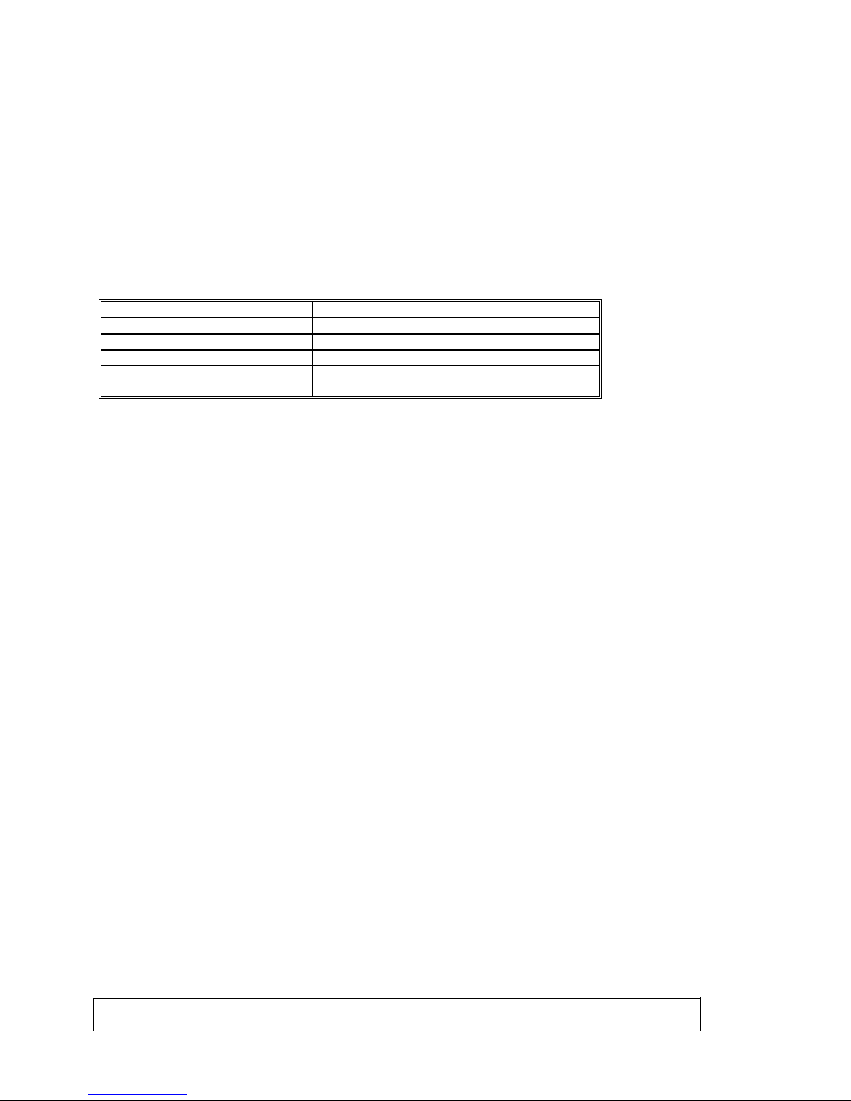
2.13.1 D
Output Voltage range -10.000 V to +10.000 V
Typical Current source/sink at 5V output 5 mA 5 mA
DAC resolution 18 bits 12 bits
Accuracy 23°C ± 10°C One Year 0.015% ± 350 µV
Typical settling time 3 S (rate set to 2/s) 1 ms
Typical source resistance
[1] An Aperture 3ms or higher is required for the clos e. set to 13 ed loop mod
C Voltage Source
Parameter Closed Loop [1] Open Loop
1.0% ± 35 mV
250 Ω
2.13.2 AC Voltage Sourc
The AC Voltage source has two ranges. 900 m
generating 5 mV t 9.3V while 0 o n generate 300mV to 7.2V RMS.
Parameter Specification
Ranges 900mV and 8V
Output Voltage, sine wave 30mV to 7.2 V RMS (0.14 to 20.0V peak-to-peak)
DAC resolution 12 bits
Typical Current Drive at 3.5V RMS 3 mA RMS
Accuracy 18 C to 2
Typical settling time (f-out > 40 Hz) 0.5 s
Typical source resistance
Frequency range / resolution 10 Hz to 100 kHz / 10 mHz
SFDR (spurious free dynamic range) 60dBc
THD (total harmonic distortion) 59dBc
Frequency stability 100 ppm ± 10 mHz
[1] 166ms er Aperture is for prop ed loop mo
°
8°C One Yea
or high required er clos de.
the higher range ca
r
e
V range and 8V range. The lower range is capable of
ACV spec + 0.8% ± 20 mV
250 Ω
2.13.3 DC Current Source
Range Comp
1.25 µA
12.5 A 5 A 10 A 1% + 100 A µ
125 µA
liance Voltage Resolution [1] Minimum level
4.2 V 500 pA
4.2 V
4.2 V
η η η
50 ηA 100 ηA 1% + 500 ηA
1 ηA 1% + 10 ηA
Accuracy 23
°C ± 10°C One Year
1.25 mA 4.2 V
12.5 mA 1.5 V
[1] Resolution without Trim DAC. The use of the Trim DAC can improve the resolution by a factor of 10, but it has
be set separately since it is not calibrated.
to
2.14 Accuracy Notes
Signametrics 24
500 ηA 1 µA 1% + 5 µA
5 µA 10 µA 1% + 50 µA

Important: all accuracy specifications for DCV, Resistance, DCI, ACV, and ACI apply for the time periods show
in the respective specification tables. To meet these specifications, Self Calibration must be performed once a day o
as indicated in the specification table. This is a simple software operation that takes a few sec
erformed by calling Windows command DMMCal(), or selecting S-Cal in the control panel.
p
onds. It can be
n
r
These products are capable of continuous m
second (rps). In general, to achieve 7-1/2 D
6-1/2 digit resolution requires at least 10ms Aperture. For 5-1/2 use at lea
easurement as well as data transfer rates of up to 20,000 readings per
igits of resolution, the Aperture should be set to 0.5s or a higher value.
st 625us Aperture.
2.15 Other Specifications
Temperature Coefficient over 0°C to 50°C Range
• Less than 0.1 x accuracy specification per °C At
Aperture
• 2.5
• In Triggered modes Aperture is limited to 160ms or shorter.
Read Interval
• 47
ardware fa Single PCI slot
H
Overload Protection (voltage inputs) 330 VDC, 250 VAC
Isolation 330 VDC, 250 VAC from Earth Ground
Maximu 8x10
1x10⁶ Volt x Hz Common Mode input (from Voltage HI or
S
afety 0-1, Installation Category II.
alibration Calibrations are
C
Temp at n ra -10°C to 65°C
Temperature Range Storage -40°C to 85°C
(user selectable)
• 625 µs to 2s in 26 di screte values, SM2060 (approx. 0.5 t
µ
s to 2s in 31 discrete values, SM2064 (approx. 0.
(user selectable)
• 47µs to 65ms, 1µs steps in Trigger modes, SM2064
• 730
• 916
Inter ce
m Input (Volt x Hertz)
er ure Ra ge Ope ting
µ
s to 65ms, 1us steps in Trigger modes, SM2060
µ
s to 1s, 1µs step o , in command/respons
µ
s to 1s, 1µs ste el s, in command/respon
Size SM2060, SM2064: 4.5” X 8.5” (PCI form
SMX2060, SMX2064: Single 3U PXI
DMM Internal Temperature sensor accuracy ±1°C (SM2064)
P
ower +5 volts, 300 mA maximum
Note: Signam
accessories without notice.
etrics reserves the right to make changes in materials, specifications, product functionality, or
23C ± 5°C
o 1,400 readings per second)
5 to 20,000 readings per second)
s bel w 65ms e modes, SM2064
ps b ow 65m se modes, SM2060
6
Volt x Hz normal mode input (across Voltage HI &
LO).
LO relative to Earth Ground).
Designed to IEC 101
performed by Signametrics in a computer at
23°C internal tem
stored in a text file.
perature rise. All calibration constants are
at)
or CompactPCI slot
25 Signametrics

Accessories
v SM2060 series DMM’s, which can be purchased directly from
Se eral accessories are available for the
Signametrics, or one of its approved distributors or representatives. These ar
e some of the accessories available:
• DMM probes SM-PRB ($15.70)
• DMM probe kit SM-PRK ($38.50)
• Deluxe probe kit SM-PRD ($95.00).
• Shielded SMT Tweezers Probes SM-PRSMT ($24.90).
• Multi Stacking Double Banana shielded cable 36” SM-CBL36 ($39.00).
• Multi Stacking Double Banana shielded cable 48” SM-CBL48 ($43.00).
Mini DIN Trigger, 6-Wire
• Ohms connector SM2060-CON7 ($14.00).
• Lab View VI’s library SM204x.llb (free).
• Extended 3 Year warrantee (does not include calibration) $150.00 for SM2060 and SMX2060, $240 for the
SM2064 and SMX2064.
Signametrics 26

3.0 Getting Started
After unpacking the DMM, please inspect for any shipping damage that may have occurred, and report any claims
to your transportation carrier.
The DMM is shipped with the Digital Multimeter module; Installation CD and a floppy disk that contain the
calibration and verification files. Also included is the Certificate of Calibration.
3.1 Setting the DMM
The SM2060 series DMM’s are PCI plug-and-play devices and do not require any switch settings, or other
adjustments prior to installation.
The SM60CAL.DAT file supplied with your DMM has a unique calibration record for that DMM (See
"Calibration" at the end of this manual.) When using multiple DMM’s in the same chassis, the SM60CAL.DAT
file must have a calibration record for each DMM. Append the unique calibration records of each DMM into one
SM60CAL.DAT file using a text editor such as Notepad. The default location for the SM60CAL.DAT file is at
the root directory C:\.
3.2 Installing the DMM Module
Warning
To avoid shock hazard, install the DMM only into a personal computer that has its power line connector
connected to an AC receptacle with an Earth Safety ground.
After installation, check to see that no loose wires or ribbon cables infringe upon any of the internal circuits
of the DMM, as this may apply measurement voltages to your computer, causing personal injury and/or
damage to your computer!
Caution: Only install the DMM module with the power turned OFF to the PC!
Use extreme care when plugging the DMM module(s) into a PCI bus slot. If possible, choose an empty slot away
from any high-speed boards (e.g. video cards) or the power supply. Please be patient during the installation
process! The DMM comes with 4 safety-input jacks. Because of their necessary size, they are a tight fit in many
PC chassis. Insert the bracket end of the DMM into your PC first, watching for any interference between the safety
input jacks and your PC chassis. “Sliding” the bracket end of the DMM into the chassis may be helpful. Be
patient! You should only have to install it once!
3.3 Installing the Software
It is recommended that you first plug in the DMM into the PC chassis, than turn on the computer power. The first
time you power up your computer with the DMM installed, your computer will detect it as new hardware and
prompt you for a driver. The driver your computer requires is located on the installation CD (SM2060.INF).
Following the above driver installation, run the ‘SETUP’ program provided on the CD. This takes care of all
installation and registration requirements of the software. If you are installing the DMM on a computer that had an
SM2060 series install in it, you should first uninstall the old software. Also make sure you backup and remove the
old calibration record (SM60CAL.DAT). For a clean reinstallation remove all INF files containing reference to the
Signametrics DMM. Depending on operating system, these files will be located at Windows\inf, Windows\inf\other
or WINNT\inf. The files will be named Oemx.INF where x is 0,1,2,… and/or SIGNAMETRICSSM2060.INF. If
present, these files will prevent “Found New Hardware” wizard from detecting the new DMM.
27 Signametrics
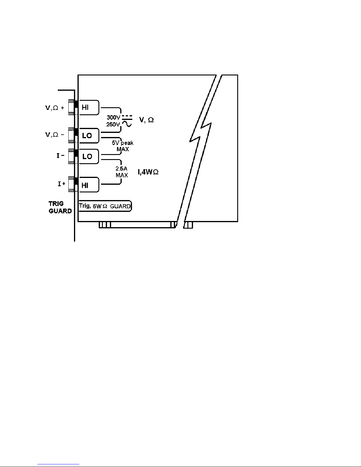
3.4 DMM Input Connectors
Before using the DMM, please take a few moments and review this section to understand where the voltage,
current, or resistance and other inputs and outputs should be applied. This section contains important
information concerning voltage and current limits. Do not exceed these limits, as personal injury or damage
to the instrument, your computer or application may result.
Figure 3-1. The DMM input connectors.
V, Ω + This is the positive terminal for all Volts, 2WΩ, capacitance, diode and inductance measurements, and for
sourcing of VDC, VAC and IDC. It is also the Source HI for 4WΩ measurements. The maximum input across V, Ω
+ and V, Ω - is 300 VDC or 250 VAC when in the measuring mode. When in the sourcing mode, the maximum
input allowed before damage occurs is 100 volts.
V, Ω - This is the negative terminal for all Volts, 2WΩ, capacitance diode and inductance measurements, and or
sourcing of VDC, VAC and IDC. It is also the Source LO for 4WΩ. Do not float this terminal or any other
DMM terminal more than 300 VDC or 250 VAC above Earth Ground. (Also, see Trig, 6W Guard below.)
I + This is the positive terminal for all Current measurements. It is also the Sense HI for 4WΩ measurements and
6WΩ guarded measurements. The maximum input across I, 4WΩ + and I, 4WΩ - is 2.5 A. Do not apply more
than 5 V peak across these two terminals!
I – This is the negative terminal for all Current measurements. In the Current modes, it is protected with a 2.5 A,
250 V Fast Blow fuse (5 x 20 mm). It is also the Sense LO for 4WΩ measurements and 6WΩ guarded
measurements. V, Ω - and I, 4WΩ - should never have more than 5 V peak across them.
Signametrics 28
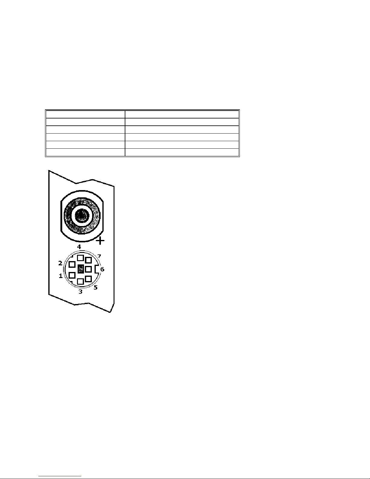
TRIG / GUARD Both the Trigger and Guard functions are at the DIN-7 connector. This group of pins includes
the positive and negative hardware trigger input lines and the two SM2064 Guarded Measurement Force and Sense
signals. The external trigger initiates reading(s) into the onboard buffer, and the 6W guard signals facilitate incircuit resistor measurements by means of isolating a loading node. The DIN-7 plug can be ordered from
Signametrics and is also available at many electronic hardware distributors. The connector is generically referred to
as a mini DIN-7 male. The trigger signal should be in the range of 3 V to 12 V peak. The two 6W guard signals
should never have more than 5 V peak across them.
Warning! The DIN connector pins are protected to a maximum of 35 V with respect to the PC chassis and
any other DMM terminal. Do not apply any voltages greater than 35 V to the DIN connector pins. Violating
this limit may result in personal injury and/or permanent damage to the DMM.
DIN-7, Pin number Function
2 Sync output, referenced to pin 4
7 External Trigger input, Positive
4 Trigger and Sync Common
1 Guard Source (SM2064)
6 Guard Sense (SM2064)
DIN-7 Connector Pin Description, view from bracket side.
3.5 Starting the Control Pane
You can verify the installation and gain familial rity with the DMM by exercising its measurement functions using
the Windows based Control Panel. To run the control panel, double click the “SM2064.EXE” icon. If you do not
hear the relays click, it is most likely due to an installation error. Another possible source for an error is that the
SM60CAL.DAT file does not correspond to the installed DMM.
When the DMM is started the first time, using the provided control panel (SM2064.EXE), it takes a few extra
seconds to extract its calibration data from the on-board store, and write it to a file C:\SM60CAL.DAT
The Control Panel is operated with a mouse. All functions are accessed using the left mouse button. When the
DMM is operated at very slow reading rates, you may have to hold down the left mouse button longer than usual for
the program to acknowledge the mouse click.
29 Signametrics

Note: The SM2060 front panel powers up in DCV, 0.5s Aperture, 0 Read Interval and 240 V range. If the DMM
operated in Autorange, with an open input, it will switch between the 2.4V and 24V ranges every few seconds, a
range change occurs. This is perfectly normal with ultra high impedance DMM’s such as the SM2060. This
phenomenon is caused by the virtually
put will read whatever charge is associated with the signal conditioning of the DMM. As this electrical charge
in
changes, the SM2060 will change ranges, causing the range switching. This is normal.
infinite input impedance of the 2.4V DC range. On these ranges, an open
3.6 Using the Control Panel
is
s a
The Control Panel for the SM2064. The three main groups include Measure, Source and Figure 3-2.
nge buttons. The Range but
Ra tons are context sensitive such that only “240m, 2.4, 24, 240 and 330
appear when in AC Voltage Function is selected, and 2.4m, 24m, 240m and 2.4 appear when AC
Current functions is selected, etc.
Note: All of the controls described below correspond to their respective software function, which can be invoked
within your control software or as objects in a visual programming environment. T
f the SM2060 provides a powerfuo
ut are in the software.
b
DC/AC This function switches between DC and AC. This is applicable for the following DMM functions:
Voltage, Current, and Voltage-Source. If Voltage-Source is the function presently in use, the Source control under
the Tools menu can be used to set frequency and amplitude in ACV, and amplitude only in DCV and DCI.
l set of capabilities. Some of the functions are not included in the control panel,
he software command language
Relative This is the Relative function. When activated, the last reading is stored and subtracted from all
bsequent readings. This is a very important function when making low-level DCV measurements, or in 2WΩ.
su
For example, when using 2WΩ, you can null out lead resistance by shorting the leads together and clicking on
Relative. When making low level DC voltage measurements (e.g., in the µV region), first apply a copper short to
the V,Ω + & - input terminals, allow the reading to stabilize for a few seconds, and click on Relative. This will
correct for any offsets internal to the SM2060. The Relative button can also be used in the Percent and dB
deviation displays (shown below), which are activated using the
The Min/Max box can be used to analyze variations in terms of Min, Max,
Percent and dBV. This display can be activated by selecting the
Min/Max/Deviation from the Tools menue. For instance, testing a circuit
bandwidth with an input of 1V RMS, activate the Relative function with the
frequency set to 100Hz, than sweep gradually the frequency, and monitor the
percent deviation as well as the dBV error and capture any response anomalies
with the Min/Max display. The left display indicates peaking of 2.468% (0.21
dBV) and maximum peaking in the response of +56.24mV and a notch of –
10.79mV from the reference at 100Hz.
Tools in the top menu.
Aperture Box: Controls the SM2060 reading aperture. As aperture decreases, the measurement noise increas
For best accuracy set to the longest aperture acceptable for the application. Also consider the line frequency (50
Hz) of operation when setting it, as certain apertures have better noise rejection at either 50 or 60 Hz. (See
Signametrics 30
es.
/60

“Specifications” for details.). When measuring RMS values, there is no point setting the Read Interval (1/rate) to a
value shorter than 0.16s since the RMS circuitry has a settling time that is greater.
Range: Can be set to Autorange or manual by clicking on the appropriate range in the lower part of the Windows
panel. Autoranging is best used for bench top application and is not recommended for an automated test
application due to the uncertainty of the DMM range, as well as the extra time for range changes. Locking a range
is highly recommended when operating in an automated test system, especially to speed up measurements. Another
reason to lock a range is to control the input impedance in DCV. The 240 mV and 2.4 V ranges have virtually
infinite input impedance, while the 24 V and 240 V and 330 V ranges have 10 MΩ input impedance.
S_Cal: This function is the System Calibration that corrects for internal gain, scale factor and zero errors. The
DMM does this by alternatively selecting its lo l DC reference and a zero input. It is required at least once every
ay to meet the SM2060 accuracy specifications. It is recommended that you also perform this function whenever
d
e external environment changes (e.g. the temperature in your work environment changes by more than 5°C, or the
th
M2064 on board temperature sensor indicates more than a 5°C change). This function takes less than a few
S
conds to perform. Disconnect all leads to the DMM before doing this operation. Keep in mind that this is not a
se
bstitute for periodic calibration, which must be performed with external standards.
su
ca
losedLoop: This check box selection is used in conjunction with the AC and DC Voltage-Source functions of the
C
M2064. When checked, the DMM monitors the output level and continuously applies corrections to the output
S
vel. When not checked, the DMM is a 12-bit source vs. 16 bits in the ClosedLoop mode.
le
penCal: This check box selection is used in conjunction with inductance measurement. It is necessary to perform
O
pen Terminal Calibration using this control, prior to measuring inductance. This function characterizes both the
O
ternal DMM circuitry as well as the probe cables. To perform OpenCal, attach the probe cables to the DMM,
in
leaving the other end of the probe cables open circuited. Then, activate the Op
enCal button.
Sources Panel:
There are three function buttons in the Source group (SM2064 only). The V, I, LEAK buttons
select one of three source functions, Voltage (DC and AC), IDC and Leakage. The Sources Panel is automatically
enabled when one of the source functions is enabled. It can also be invoked using the Sources Panel selection
under the
Tools menu. This panel allows the entry of values for all of the source functions, including Leakage.
The V-OUT Scroll bar and Text box are used to
set the Voltage for DC and AC Volts as well as
for Leakage. When sourcing ACV, the voltage is
in RMS and the FREQ. Scroll bar and Text box
control the frequency of the source. It is also
used to control inductance frequency. When
sourcing DC current
controls. W
hen measuring timing or freqeuncy
, use the I-OUT set of
the THRESH set of controls is used for
comperator threshold. All of the source controls
are context sensitive and will be enabled when
31 Signametrics

.0 DMM Operation and Measurement Tutorial
4
Most of the SM2060 measurement functions are accessible from the Windows Control Panel (Figure above). All of
the functions are included in the Windows DLL driver library. To gain familiarity with the SM2060 series DMM’s,
run the Windows ‘SETUP.EXE’ to install the software, then run the DMM, as described in the previous section.
This section describes in detail the DMM’s operation and measurement practices for best performance.
4
.1 Voltage Measurement
Measures from 0.1 µV to 330 VDC or 250 VAC. Use the V, Ω + and V, Ω - terminals, being certain to always lea
the I+, I- and DIN-7 terminals disconnected. Use the AC/DC button on the Control Panel to switch between AC
and DC.
Making Voltage Measurements is straightforward. The following tips will allow you to make the most accurate
voltage measurements.
ve
4.1.1 DC Voltage Measurements
n making very low-level DCV measurements (<1 mV), you should first place a cop
Whe per wire shorting plug
across the V, Ω + and V, Ω - terminals and perform Relative function to eliminate zero errors before making your
measurements. A common source of error can come from your test leads, which can introduce several µVolts of
error due to thermal voltages. To minimize thermal voltaic effects, after handling the test leads; you should wait
few seconds before making measurements. Signametrics offers several high q
vel measurements.
le
uality probes that are optimal for low-
a
Note: The SM2060 front panel powers up in DCV, 0.5s aperture, 240 V range. If the DMM is operated in
Autorange, with an open input, The DMM will keep changing ranges. This is perfectly normal with ultra high
impedance DMM’s such as the SM2060. The virtually infinite input impedance of the 240 mV and 2.4 V DC
ranges causes this phenomenon. On these ranges, an open input will read whatever charge is associated with the
signal conditioning of the DMM. As this electrical charge accumulates, the SM2060 will change ranges.
V
4.1.2 True RMS AC Voltage Measurements
ACV is specified for signals greater than 1mV, from 10 Hz to 100 kHz. The ACV function is AC coupled, and
measures the true RMS value of the waveform. As with virtually all true-RMS measu
not read a perfect zero with a shorted input. This is normal.
ACV measurements, if poss
See Figure 4-1, below. This prevents any “Common Mode” problems from occurring (Common Mode refers to
floating the SM2060 V,Ω LO above Earth Gr
cause the PC to hang-up under high V X Hz input conditions. In many systems, grounding the source to be
measured at Earth Ground (being certain to avoid any ground loops) can give better results.
he settling time and low end bandwidth of the RMS function are effected by the status of the Fast RMS co
T
circuit. When fast RMS is selected, the RMS settling time is about 10 times faster, but the low end frequency is
significantly increased.
ible, should have the NEUTRAL or GROUND attached to the SM2060 V,Ω - terminal.
ound.) Common Mode problems can result in noisy readings, or even
ring meters, the SM2060 may
ntrol
Signametrics 32

Figure 4-1. Make Voltage ACV measurements with the source ground attached to the SM2060 V,Ω - to
minimize “Common Mode” measurement problems.
4.1.3 AC Peak-to-Peak and Crest Factor (SM
Mea a repetitive waveform between 30 Hz
surement of Peak-to-Peak, Crest Factor and AC Median values requires
and 100 kHz. The DMM must be in AC voltage measurement mode, with the appropriate range selected. Knowin
the Peak-to-Peak value of the waveform is useful for setting the Threshold DAC (described below). This latter
function is a composite function, and may take over 10 seconds to perform.
2064)
g
4.1.4 AC Median Value Measurement (SM2064)
To better understand the usage of this function, you should note that the DMM makes all AC voltage measurements
through an internal DC blocking capacitor. The voltage is thus “AC coupled” to the DMM. The measuremen
the Median value of the AC voltage is a DC measurement performed on the AC coupled input signal. This
measurement returns the mid-point between the positive and negative peak of the waveform. The Median value is
sed for setu
ea at the comparator input
m sure the frequency of a low duty cycle, low amplitude AC signals since there is DC shift
due t the comparator
threshold level). For further information on the usage of AC Median value and Peak-to-Peak measurements, and
the Threshold DAC, see the “Frequency and Timing Measurements” section below.
ting the comparator threshold level for best counter sensitivity and noise immunity. (It is difficult to
o the internal AC coupling. The SM2064 overcome this problem by allowing you to set
his function requires a repetitive signal. The DMM must be in AC voltage measurement mode, with the
T
appropriate range selected.
t of
4.2 Current Measurements
The SM2060 measures AC and DC currents between 100 ηA and 2.5 A. Use the +I, 4WΩ terminals, being certain
to always leave the V,Ω + & - terminals disconnected. Use the AC/DC button to switch between AC and DC. Th
C current is an AC coupled True Re MS measurement function. See figure 4-2 for connection.
A
The . The 2.4mA and 24mA ranges utilize a 10Ω shunt,
Current functions are protected with a 2.5 A, 250 V fuse
while the 240mA and 2.4A ranges use a 0.1Ω shunt. In addition to the shunt resistors, there is some additional
parasitic resistance in the current measurement path associated with the fuse and the internal wiring. The result is a
burden voltage of up to about 250mV.
33 Signametrics

4.2.1 Extended DC Current Measurements (SM2064)
In addition to the 2.4mA, 24mA, 240mA and 2.4A, the SM2064 has also four DC current ranges; 240nA, 2.4uA,
24uA and 240uA ranges. The lower three ranges are implemented with a “Virtual Zero Shunt” technology,
commonly associated with specialized Micro Amp meters. It has an ultra low noise low leakage that renders it
useful for measuring down to few Pico-amperes. This means that supe
utput DACs of such devices as heart pace makers, or low semiconductor leakages can be measured with practically
o
no voltage drop.
In order to measure down to Pico Amperes it may be necessary to guard the terminals as described in the
section of this manual (4.3.8
arning! Applying voltages greater than 35 V to the I+, I- terminals can cause personal injury and/or
W
damage to your DMM and computer! Think before applying any inputs to these terminals!
Guarding High Value Resistance Measurements (SM2064))
r low currents from such circuits as Current
guarding
.
Figure 4-2. AC and DC Current measurement connection.
4.2.2 Improving DC Current Measurements
When making sensitive DC current measurements disconnect all terminals not associated with the measurement.
User the Relative function while in the desired DC current range to zero out any residual error. Using the S-Cal
(DMMCalibrate ()) prior to activating Relative will improve accuracy further. Although the SM2060 family is
designed to withstand up-to 2.4A indefinitely, be aware that excessive heat may be generated when measuring
high ts. In
er AC or DC currents. If allowed to rise this heat may adversely effect subsequent measuremen
consideration with this effect, it is recommended that whenever practical, higher current measurements
short time intervals. The lower two ranges of DC current may be effected by relay contamination. If the
measurements seem unstable or high, while in IDC measurement, apply between 20mA and 50mA DC to the
current terminals and clean the K2 relay using the DMMCleanRelay(0, 2, 200). Repeat this until the measuremen
are stable.
be limited to
4.2.3 DC Current Measurements at a specific voltage
The leakage measurement function can be used to measure low-level currents at a specific voltage. T
function uses the top and bottom terminals of the SM2064. It measures low level DC cu
rrents with a
specified DC voltage applied to the DUT.
Signametrics 34
his
ts

4.3 Resistance Measurements
Resistance is measured using eight (six in the SM2060) precision curre
sistance value. Most measurements can be made in the 2-wire mode. The 4-wire ohms is used to make low value
re
resistance measurements. All resistance measurement modes are susceptible to Thermo-Voltaic (Thermal EMF)
errors. See section 4.3.5 for details.
nt sources, with the DMM displaying the
4.3.1 2-Wire Ohm Measurements
The DMM measure using 240Ω to 24 MΩ ranges. The SM2064 adds 24 Ω and 240 MΩ ranges, as well as extended
resistance to 100 G. Use the V,Ω+, V,Ω- terminals for this function. Be certain to disconnect the I+, I- terminals
in order to reduce leakage, noise and for better safety.
Most resistance measurements can be made using the simple 2-wire Ohms method. Simply connect V,Ω+ to one
end of the resistor, and the V,Ω- to the other end. If the resistor to be measured is less than 30 kΩ, you should null
out any lead resistance errors by first touching the V,Ω+ and V,Ω- test leads together and then performing a
Relative function. If making measurements above 300 kΩ, you should use shielded or twisted leads to minimize
noise pickup. This is especially true for measurements above 1 MΩ.
You may also want to control the Ohms current used in making resistance measurements. (See the Specifications
section, "Resistance, 2-wire and 4-wire", for a table of resistance range vs. current level.) All of the Ohms ranges of
the SM2060 have enough current and voltage compliance to turn on diode junctions. For characterizing
semiconductor part types, use the Diode measurement function. To avoid turning on a semiconductor junction, you
may need to select a higher range (lower current). When checking semiconductor junctions, the DMM displays a
resistance value linearly related to the voltage across the junction.
or applications requiring voltage and current controlled resistance measurements, use the Extended Resistance
F
Measurement function as well as active guarding is available with the SM2064.
4.3.2 4-Wire Ohm Measurements
4-wire Ohms measurements are advantageous for making measurements below 330 kΩ, eliminating lead resistance
errors. The Voltage (V,Ω) Input terminals serve as a current source to stimulus the resistance, and the I, 4WΩ Inpu
terminals are the sense inputs. The Source + and Sense + leads are connected to one side of the resistor, and the
Source - and Sense - leads are connected to the other side. Both Sense leads should be closest to the body of the
resistor. See Figure 4-
4-wire Ohm makes very repeatable low ohms measurements, from 100 µΩ (10 µΩ for SM2064) to 330 kΩ. It is
n
ot recommended to use 4WΩ when making measurements above 100
ci t of leads can actually
litated up to 330 kΩ. 4-wire measurements are disabled above 330 kΩ since the extra se
fa
degr
ade the accuracy, due to additional leakage and noise paths.
3.
kΩ, although 4-wire ohms measurements are
t
35 Signametrics

Figure 4-3. The I- and I+ sense leads should be closest to the body of the resistor when making 4WΩ
measurements.
4.3.3 Using Offset Ohms function (SM2064)
Inadvertent parasitic leakage currents, Thermo-voltaic voltages and other sources of voltage errors in a circuit can
be the cause of inaccuracies in resistance measurements. This is common particularly when making measurements
f active circuit. Many users, unaware of the above issues, select very poor switching systems prone to high
o
Thermal Errors that introduces some very high offset voltages, be it in 2-Wire or 4
O ll ome error. En lso easure internal resistance of low value hms can a
v rc s ries, ow se al 2-Wire or 4-
oltage sou
Awire Ohms DMMSetOffsetOhms()
f Wh U d interv e twice negati sitive polarity voltages can be
corrected as long as the total voltage incl resistan ement voltage plus the parasitic voltage are less
than 0.5V. To calculate this voltage consult the specification part of this ma
O ge. ul this fun ALSE. ion is i ented only with the SM2064.
hms ran The defa t value of ction is F This funct mplem
4.3. 6-wi Gua esis Meas ent (
T 64 a 6-wire r e measur ethod. It to make resistance
he SM20 provides guarded esistanc ement m is used
m est has other shunting paths, which
easurements when the resistor-under-t can cause inaccurate readings. This
ethod isolates the resistor-under-test by maintaining a guard voltage at a user-defined node. The guard voltage
m
prev
ents the shunting of the DMM Ohms source current from the resistor-under-test to other components. The
Guard Source and Guard Sense terminals are provided at pins 1 and 6 of the DIN connector respectively.
Warning! The DIN connector pins are only protected to a maximum of 35 V with respect to the PC chassis
or any other DMM terminal. Do not apply any voltages greater than 35 V to the DIN connector pins.
Violating this limit may result in personal injury and/or permanent damage to the DMM.
Example: Assume a 30 kΩ resistor is in parallel with two resistors, a 510 Ω and a 220 Ω, which are connected
series with each other. In a normal resistance measurement, the 510 Ω and 220 Ω would “swamp” the measurem
shunting most of the DMM Ohms source current. By sensing the voltage at the top of the 30 kΩ, and then applying
this same voltage to the junction of the 510 Ω and 220 Ω, there is no current flow through the shunting path. With
this “guarding”, the SM2064 accurately measures the 30 kΩ resistor.
eviate s
es such a
connection, and set the Offset Ohm
of this
various batte
Runction. en set T E, the rea al will b
abling it can a
low voltage p
uding the
be used to m
er supplies and nsors. Use the norm
s to the enabled or disabled state using the
as set. Both
ce measur
4 re rded R tance urem SM2064)
-Wire measurements. Offset
ve and po
nual for the specific current for each
in
ent
Signametrics 36

Figure 4-4. 6-wire guarded in-circuit ohms measurement configuration.
The current compliance of the Guard Force is limited to a maximum of 20 mA and is short circuit protected. The
. Due to
resistor connected between the low of the 4-wire terminals and the guard point is the burden resisto
: R
the limited guard source current, this resistor can not be lower than R
ohms sourc
e current for the selected range, and R
Ω range and measuring a 300 Ω resistor imposes a limit on R
resistor, R
, does not have this limit imposed on it, selecting the measurement polarity, Ra can become Rb and vise
a
is the resistance being measured. For example, selecting the 330
x
of at least 15 Ω or greater. Since the top burden
b
bmin
= Io * Rx / 0.02, where Io is the
bmin
versa. For cases where this limit is a problem, simply set the measurement polarity such that R
r, or R
b
is the higher of the
a
two burden resistors.
To measure values greater than 330 kΩ using the 6-wire guarded method, it is necessary to select the 2-wire ohms
function, and maintain the 6-wire connection as in Figure 4-4 above.
4.3.5 Extended Resistance Measurements (SM2064)
The Extended Resistance measurement function complements the standard resistance measurement. While the
standard resistance measurement forces a constant current, this function forces a variable voltage. It is ratiometric
in its operation, meaning it is using internal precision resistors to establish references for the various ranges. The
maximum test current is defined by the selected range. Negative Over-Range is reached when the test current
exceeds this limit. Positive Over-Range is declared when the current is lower than 0.04% of the current limit. The
test current is equal to the set test voltage divided by the measured resistance value.
Ranges are defined in terms of their current limit rather than resistance. The lowest range’s current limit is set at
24µA, therefore the lowest resistance it can measure with the test voltage programmed to 10V, is about 400k. With
the test voltage set to 0.1V the minimum value is about 4k. The next range’s limit is 2.4µA which corresponds with
4M at 10V and 40k with 0.1V. The highest range current is limited to 240nA, which implies that the lowest
resistance it can measure with 10V source is 40M and the lowest resistance it can measure with 0.1V is 400k. The
highest range practical measurement limit is as high as 10G. The connection topology with optional active
guarding is depicted in Figure 4-7.
Set the test voltage using the DMMSetDCVSource() function. Due to the availability of a higher test voltages than
is available with the normal resistance function, as well as the ratiometric method, this measurement function is best
for high value resistors such as measuring leaky cables. Further benefit in setti
rning on of semiconductor junctions while testing high value resistors. The combined ability to limit both voltage
tu
and current is significant in test applications where the destruction of a delicate sensor is a concern. The built-in
voltage source can be set between -10V an
easurement noise. For instance measurinm
d +10V. Also consider that with lower voltages, there is increase in
g 10Meg resistor with 0.1V is noisier than using 1V.
ng a specific test voltage is to prevent
37 Signametrics

Add e testing high value resistive elements such as cables, transformers, and other leaky itional applications includ
objects such as printed circuit boards, connectors and semiconductors.
Range Measurement range Resolution Voltage Range Current Limit
400kΩ 1kΩ to 100MΩ 10Ω
4MΩ 10kΩ to 1GΩ 100Ω
40MΩ 100kΩ to 10GΩ 1kΩ
±0.02V to ±10.0V 25µA
±0.02V to ±10.0V 2.5µA
±0.02V to ±10.0V 250nA
Figure 4-7. Gua g rove ccurac suring high valu stors using the Extended
Resistance su e ho
.6 Eff ts f Th rmo- ffset
4.3 ec o e Voltaic O
Resistance measurem sitiv hermo-Volt errors
caused by p st ont
methods, inclu ire, re and 3-Wire ( hms).
system in w ign are d to MM via a rela
products do not provi
µV. With rel ont n th
SM2060 24 e a single re ected to any lo
(about 2 m h ea
and set ‘rela
contacts, re ries
error as in
sever
wh
th
Resistanc as m r ue to Thermo sets.
SM2066
33 Ω
330 Ω
3.3 kΩ
33 kΩ
330 kΩ
Ohm
ge Ran
rdin impns a y when mea e resi
mea rem t met d.
ents are sen e to T aic (Thermal EMF) . These error voltages can be
oor te leads, relay c acts and s in the measure ath. They affect all measurement
ding 2-W 4-Wi 6-Wire guarded 2-Wire o To quantify this error, consider a
hich s als route the D y multiplexing sy Many vendors of switching
de Thermal F spec it is not uncommo ind relays that have more than 50
al ay c acts i e path, n be significant. This error can be measured using the
0mV DC range. To do t is, clos lay that is not conn ad, wait for a short time
inutes), t an m sure t voltage orted relay contac to short the DMM leads
tive’ lear MM offset p asurement. To cal error, count all relay
to c i t rior to the me culate worst-case
ich a n se with measu +, V, Ω- terminal terminals in 4-
). Mul y th ount the The Use Ohms l voltage to resistance
tiplwis by rmal EMF voltage. aw to convert t
e fol ing le.
lo tab
he D
c
,
EM ification, an n to f
h
he across the sh ts. Make sure
the
other element ment p
stem.
d
the error ca
rement (V, Ω s in 2-Wire, and I+, I-
e Me ure ent E rors d -Voltaic off
s D
Current
10 m
A
1 m
A
1 m
A
100 uA
10 uA
MM
esoluti
R on
µΩ 1 0 mΩ
10 mΩ 1 100 mΩ
0 µΩ 10 00 mΩ
10 mΩ 1 1 Ω
mΩ 10 00 mΩ
1 mΩ 1 1 Ω
mΩ 10 Ω 10 10 0 mΩ 1 Ω
0 mΩ 1 0 Ω 100 10 Ω 1 Ω
E
rror due to E
10
µV EMF 1
rror due to
00 µV EMF
Error due to
1mV EMF
hisWire mode
Signametrics 38

1 uA
33 MΩ
330 MΩ
4.3.7 Gu rdi g Hi h Val ance Measurements (SM2064)
Measur sist ing t Wire function re tention. Due to t
involved during such measurements, noise pickup an
m
dielectric, if a significant length is involved, an error would result due to leakage. Figure 4.8 exemplifies this er
source. It is important to emphasize that in addition to the finite leakage associated with the distributed resistan
R
c
ing high value re ors us he 2- quire special at he high impedances
easurement it is important to use good quality shielded cables with a low leakage dielectric. Even with a good
, there must also be a voltage present between the two conductors, the shield and the center l
L
urrent to develop. Provided there was a way to eliminate this voltage, leakage would have been eliminated.
100 nA
10 nA
Ω 10 00 Ω 3.3 MΩ
1 Ω 1 10 Ω
0 Ω 10 kΩ 100 10 0 Ω 1 Ω
kΩ 1 0 kΩ 100 10 kΩ 1 kΩ
a n g ue Resist
d leakage could be very significant. To improve this type of
ead, for leakage
ror
ce,
Figure 4-8. Depiction of the error caused the cable leakage, R
The SM2064 ide a l that can be c hield a
the dielect it ista ith ield voltage guarded with Vx, as indicated
between d an he h and therefore hroug
prov s an ctive guard signa onnected to the s nd prevent the leakage caused by
ric’s fin e res nce. W the sh in Figure 4-9, there is 0V
the shiel d t igh sense wire, no current flows t h R
.
L
L
.
Figure 4-9. Guarding improves accuracy in 2-W ire measurement while testing high value resistors.
4.4 Leakage Measurements (SM2064)
The SM2064 measures leakage currents by applying a DC voltage across the device under t
urrent through it. Three ranges are provided, 240nA, 2.4uA and 24uA. The voltage can be set between -10V and
c
+10V. See Figures 4-10 for connection. The DC voltage at which leakage is measured is set using
est, and measuring the
39 Signametrics

functions.
eadStr() or DMMReadNorm() DMMSetDCVSource(). Leakage current is read using DMMRead(), DMMR
Figure 4-10. Leakage test configuration; reverse diode leakage at 5V.
4.5 Measurement Timing
4.5.1 Aperture
The SM2060 and SM2064 DMM’s have several parameters governing measurement timing, including Aperture,
Read Interval and Overhead time. To maintain low noise and high accuracy, the DMM shuts down all
communications and other operations while converting. All other operations such as data transfers and command
processing are performed while the A/D is not active. The A/D is an integrating type and has a time during which it
integrates (a sort of averaging) the input. This time is the A/D Aperture. It is significant, particularly when it relates
to noise rejections. For instance, in the presence of 60Hz power line environment, there is significant 60Hz and its
harmonics which can contaminate a measurement. Setting the Aperture time to an integer multiple of this frequency
dramatically reduces this interference. Apertures of 16.667ms, 33.33ms, 66.667ms, etc. provide this rejection.
Aperture values are made up of a set consisting of 31 discrete values. It is set using the DMMSetAperture()
command, the SM2064 can set it between 2.5us and 5.066s, and the SM2060 can set it between 625us and 5.066s.
While using the various Trigger modes, the Aperture time must be set to 160ms or a lower value.
4.5.2 Read Interval
The Read Interval parameter is the length of time the DMM makes a measurement, including the transfer of the
measurement results. Both the Aperture and Read Interval can be set within their specified limits. Setting them
allows control over measurement timing. Figure 4-11 depicts the various timing elements associated with each
DMM reading cycle. The actual measurement rate is the reciprocal of the actual Read Interval (RI). The time
intervals indicated “Command Reception and Processing” and the “Process & Transmit Data”, are overhead times.
This means that with the Read Interval set to 0, the DMM sets the Delay to 0, resulting in a minimal Read Interval
consisting of the sum of the Aperture and the two overhead times indicated below. Set the Read Interval value using
the DMMSetReadInterval() functions. Keep in mind that setting it to a value lower than the Minimum Read Interval
indicated in the tables below will result in it being the table value.
Signametrics 40

Figure 4-11. Anatomy of a measurement
Power Line Rejection Command/Response mode
min. Read Interval(s) / max
meas. rate(Hz)
Aperture 60
50Hz 400Hz
H/W Trigger mode min. Read
Interval(s) / max meas. Rate
(Hz)
Hz
5.1200s [1]
5.0666s [1]
2.08s [1]
2.0s [1]
1.06666s [1]
960ms [1]
533.33ms [1]
480ms [1]
266.666ms [1]
160.0ms
133.33ms
80.00ms
66.6667ms
40.00ms
33.333ms
20.00ms
16.6667ms
√ √ √
5.0677s / 0.2 N/A
√
√ √
√ √ √
1.067s / 1 N/A
√
√ √
533.6ms / 2 N/A
√
√ √
268ms / 4 N/A
√
√ √ √
134ms / 8 133.5 ms / 8
√
√ √
67.2ms / 15 66.713 ms / 15
√
√ √
33.643ms / 29.72 33.38 ms / 30
√
√ √
16.77ms / 59.6 16.89 ms / 59
√
5.121s / 0.2 N/A
2.081s / 0.5 N/A
2.001s / 0.5 N/A
0.9605s / 1 N/A
480.2ms / 2 N/A
166ms / 6 160.3 ms / 6
80.4ms / 13 80.2 ms / 13
40.4ms / 25 40.32 ms / 24.8
20.098ms / 49.76 20.33 ms / 50
10ms 10.094ms / 99 10.25 ms / 97
8.333ms 8.422ms / 119 8.503 ms / 115
5ms 5.109ms / 195 5.187 ms / 185
4.16667ms 4.265ms / 234 4.274 ms / 220
2.5ms 2.598ms / 385 2.614 ms / 350
2.0833ms 2.177ms / 458 2.216 ms / 410
1.25ms 1.344ms / 744 1.380 ms / 625
1.0417ms 1.133ms / 880 1.158 ms / 864
625µS
520.83µS
312.5µS
260.42µS
130.21µS
2.5µS
719µs / 1,390 728 µs / 1,370
617µs / 1,625 622 µs / 1,610
410µs / 2,445 414 µs / 2,445
355µs / 2,825 358 µs / 2,825
215µs / 4,660 217 µs / 4,660
47µs / 21,600 45 µs / 22,200
[1] Not available with any of the Triggered modes.
Table 4.1: The SM2064 has 31 A/D apertures available, ranging from 5 Seconds to 2.5uSec
. The table contains
rvals and measurement rates. available measurement apertures and the corresponding minimum read inte
41 Signametrics

Aperture 60 50Hz 400Hz
5.1200s [1]
5.0666s [1]
2.08s [1]
2.0s [1]
1.06666s [1]
960ms [1]
533.33ms [1]
480ms [1]
266.666ms [1]
160.0ms
133.33ms
80.00ms
66.6
40.00ms
33.333ms
20.00ms
16.6667ms
10ms 10.36ms / 97 10.25 ms / 97
8.333ms 8.68ms / 115 8.503 ms / 115
5ms 5.36ms / 185 5.187 ms / 185
4.16 ms / 220 4.274 ms / 220 667ms 4.52
2.5ms 2.86ms / 350 2.614 ms / 350
2.0833ms 2.44ms / 410 2.216 ms / 410
1.25ms 1.6ms / 625 1.380 ms / 625
1.0417ms 1.39ms / 719 1.158 ms / 864
625µS
[1] Not available with any of the Triggered modes.
Power Line Rejection Command/Response mode
min. Read Interval(s) / max
meas. rate(Hz)
Hz
√ √ √
5.0677s / 0.2 N/A
√
√ √
√ √ √
1.067s / 1 N/A
√
√ √
533.6ms / 2 N/A
√
√ √
268ms / 4 N/A
√
√ √ √
134ms / 8 133.5 ms / 8
√
√ √
√
√ √
33.7ms / 30 33.38 ms / 30
√
√ √
16.9ms / 59 16.89 ms / 59
√
5.121s / 0.2 N/A
2.081s / 0.5 N/A
2.001s / 0.5 N/A
0.9605s / 1 N/A
480.2ms / 2 N/A
166ms / 6 160.3 ms / 6
80.4ms / 13 80.2 ms / 13
40.4ms / 25 40.32 ms / 24.8
20.35ms / 50 20.33 ms / 50
917µs / 1,090 728 µs / 1,370
H/W Trigger mode min. Read
Interval(s) / max meas. Rate
(Hz)
66.713 ms / 15 667ms 67.2ms / 15
Table 4.2: The SM2060 has 26 apertures available, ranging from 5 Seconds to 625uSec
available measurement apertures and corresponding minimum read intervals and measurement rates.
. The table contains all
4.6 RTD Temperature Measurement (SM2064)
For temperature measurements, the SM2064 measure and linearize RTDs. 4-wire RTD can be used by selecting the
appropriate RTD type. Any ice temperature resistance between 25 Ω and 10 kΩ can be set for the platinum t
RTDs. Copper RTDs can have ice temperature resistance values of 5 Ω to 200 Ω. The highest accuracy is obtained
from 4-wire devices, since this method eliminates the error introduced by the r
onnection configuration for RTDs is identical to 4-wire Ohms.
c
esistance of the test leads. The
ype
4.7 Internal Temperature (SM2064)
A special on board temperature senso
means to determine when to run the self-calibration function (S-Cal) for the DMM, as well as predicti
performance of the DMM under different operating conditions. When used properly, this measurement can enhan
the accuracy and stability of the DMM. It also allows monitoring of the PC internal temperature, which is important
for checking other instruments in a PC-based test system.
r allows monitoring of the DMM’s internal temperature. This provides the
ng the
ce
4.8 Diode Characterization
The semiconductor part types. This function is designed to
Diode measurement function is used for characterizing
display a semiconductor device’s forward or reverse voltage. The DMM measures diode voltage at a selected
current. The available source currents for diode I/V characterization include five DC current values, 100 ηA, 1 µA,
10 µA, 100 µA and 1 mA. The SM2064 have an additional 10 mA range. The SM2064 also has a variable current
Signametrics 42

source that can be used concurrently with DCV measurement (see “Source Current / Measure Voltage”). This
allows a variable current from 10 ηA to 12.5 mA. The maximum diode voltage compliance is approximately4 V.
Applications include I/V characteristics of Diodes, LEDs, Low voltage Zener diodes, Band Gap devices, as well a
IC testing and polarity checking. Typical current level uncertainty for diode measurements is 1%, and typical
voltage uncertainty is 0.02%.
s
4.9 Capacitance Measurement (SM2064)
The SM2064 measure capacitance using a differential charge balance (ramp) method, where variable current
utilized to
200 pF. With the exception of the 10 ηF range, each of the ranges has a reading span from 5% of range to full scale.
Capacitance values less than 5% of the selected range indicate zero. Since some large value electrolytic capacitors
have significant inductance, as well as leakage and series resistance, the Auto ranging function may not be practi
Because Capacitance measurement is sensitive to noise, you should keep the measurement leads away from noise
urces such as computer monitors. For best measurement accuracy at low capacitance values, zero the DMM using
so
the ‘Relative’ while in the 10 ηF range. The effect of the cable quality and its total capacitance is profound
particularly on low value capacitance. For testing surface mount parts, use the optional Signametrics SMT Tweeter
probes. You may increase the measurement speed by using the DMMSetCapsAveSamp() function. See figure 4
for connection.
stimulate a dV/dt across the capacitor. Use short high quality shielded probe cables with no more than
s are
cal.
-12
Figure 4-12. Measuring capacitors or inductors is best handled with coaxial or shielded probe wires.
4.10 I
A
fu tion, the advantage of this method is that the default sti
ability of this function to measure capacitors that have a very low value parallel resistance, which is impossible to
do using conventional methods. This test function operates by figuring the complex impedance and extracting from
it both, the capacitance and resistance. The measurement is practical down to a few hundred Pico Farads, and up to
several thousands micro Farads, with parallel resistances as low as 20Ω to 300Ω depending on range. Once set to
this function, use DMMRead(), DMMReadStr() and DMMReadNorm() to measure the capacitance value. To ge
the resistance value use DMMGetACCapsResist() following a read. Each of the ranges must be calibrated with
open terminals prior to making measurements. Each range must be calibrated. Do this by activating the AC-Caps
function, selecting the range to be calibrated and issuing DMMOpenCalACCaps(). The last function normalizes
the AC source signal. This open Calibration operation must be performed with the measurement cable or probes
n-Circuit Capacitance Measurement (SM2064)
second
method provided for measuring capacitors is the AC based method. Though not as accurate as the above
nc mulus is set at 0.45V peak, which is lower than a
iconductor junction on voltage. It may also be set over sem a wide range of voltages. A further advantage is the
t
43 Signametrics

plugged into the DMM, with the other end open. See figure 4-12 above for connection. If not modified by the
DMMSetACCapsLevel(
hich means that a sine wave that has a peak-to-peak amplitude of 0.9V. This level is used during both, open
w
calibration and measurements. Since the DMM is op imized for this value, and it is well below most semicond
on voltage, it is recommended no o change the level from
0.1V peak
alibration must be carried out. The results of DMMOpenCalACCaps() are kept in memory until the DLL is
c
unloaded. Repeating Open calibration periodically will resul
function must be used with a DMM
.11 Inductance Measurement (SM2064)
4
The ecision AC source with a frequency range of 20 Hz to 75 kHz. Since
inductors can vary greatly with frequency, you should choose the appropriate generator frequency. In addition
inductance, the inductor’s Q factor can be measured. A high quality coaxial or at least a shielded cable is highly
recommended. For best accuracy, perform the Open Terminal Calibration function within an hour of inductance
measurements. The Open Terminal Calibration function must be performed with the cable or probes plugged into
the DMM, but with the other end open circuited. This process characterizes the internal signal path inside the
DMM, the open application cable and the DMM circuitry. Set the Aperture to 40ms or to higher values for better
accuracy.
or best measurement accuracy at low inductance values, zero the DMM often by using the ‘
F
the leads shorted. This must be done a en Terminal Calibration operation. This Relative action
removes the inductance of the D signal path and that of the application ca
to 5V peak using the DMMSetACCapsLevel() function. Any time the stimulus level is adjusted; open
SM2064 measures inductance using a pr
) function, when making a measurement the DMM uses a default voltage of 0.45Vpk,
t uctors
t t this default value. The stimulus voltage can be set from
t in improved accuracy. AC Capacitance measurement
Aperture of at least 80ms.
Relative’ function with
fter Op measures and
MM ble.
to
4.12 Characteristic Impedance Measurem
racteristic impedance, measure the cable’sTo measure transmission line’s cha
cable ope
oot of L
r
pec
s
n) and then its inductance L (wi
/C. Be certain the cable is long enough such that both the capacitance and inductance are within the
ified measurement range of the SM2064.
th the end of the cable shorted). The cable’s impedance equals the square
ent (SM2064)
capacitance C (with the end of the
4.13 Trigger Operation
Several trigger functions are provided; some are by means of an input signal to the trigger input, and
others by means of input level.
on-board controller supervises the operation, and when conditions are valid, it captures data into its circular buffer,
or sends it back to the PC bus. The aperture must be set to a value equal or smaller to 160ms for all trigger
operations.
The Trigger functions provide for a stand-alone capture of measurements. The
4.13.1 External Hardware Trigger
The External Hardware Trigger inputs are isolated high and low input lines availabl
IN-7 connector. The External Trigger operation may be aborted using the DMMDisarmTrigger(). Read about
D
these functions in the Windows Command Language section (5.6) for details.
Warning! The DIN connector pins are only protected to a maximum of 35 V with respect to th
or any othe
Violatin
r DMM terminal. Do not apply any voltages greater than 35 V to the DIN connector pins.
g this limit may result in personal injury and/or permanent damage to the DMM.
4.13.1.1 Edge Triggered Operation
In this mode of operation, the DMM takes between 1 and 120 (or 1 and 80 if high resolution)
measurements in response to the currently set edge. Once armed, the DMM waits for this Trigger event
until it occurs, or the process is aborted (DMMDisarmTrigr(nDmm)). While waiting for the selected
trigg
er edge, the DMM continuously makes measurements and stored them to the internal buffer, utilizing
the whole buffer. Depending on the length of time prior to the trigger event, this circular buffer may or
may not be filled / over-written. For additional information a counter is provided to counts the number
times the buffer fills up while waiting for the trigger event. On reception of the trigger, the DMM takes
the number of readings specified in the DMMArmTrigger(nDmm, n) command and indicates it is ready
(DMMReady() = TRUE). These post trigger readings are stored in subsequent locations of the circular
buffer. At the end of the capture process the internal buffer pointer points to the beginning of the buffer.
Following the completion of the process, subsequent readings from the buffer will return 120-n pretrigger readings, followed by n post trigger readings. In the case where
Signametrics 44
e at pins 7 (+) and 4 (-) of the
e PC chassis
of
trigger occurred before the buffer

filled, there will be some NULL readings in the buffer, followed by pre-trigger and post-trigger is
readings. Following capture use the DMMGetTriggerInfo() function to retrieve information such as the
number of NULL readings, Pre-Trigger samples and buffer fill cycles.
4.13.1.2 Delayed Triggered Operation
In this trigger mode of operation, following the reception of the selected trigger edge, the DMM waits for
the specified delay, and then it takes from 1 to 120 (or 1 to 80 if high resolution) measurements. The
delay can be set from 10us to 1s.
The specified number of measurements is stored in the buffer. At the end of this operation, the internal
buffer pointer points to the beginning of the buffer, such that reading the buffer starts with the first sample
taken. To read all samples resulting from this operation, use one of the buffer read functions. See
DMMDelayedTrigger() function for details.
4.13.2 Analog Threshold Trigger
This mode of operation is entered by issuing the DMMArmAnalogTrigger command. In this mode, while waiting
for a trigger event, the DMM makes repeated measurements and places them in the internal buffer, as to provide
pre-trigger samples. All measurements are made using the currently set range, function, Aperture and Read Interval.
Trigger event occurs when the input value transverses through the set Threshold (dThresh) value, in the currently
set directions dictated by Edge (see DMMSetTrigPolarity). Following the trigger point, if enabled, the Sync output
is activated (see DMMSetSync), and iPostSamples measurements are taken. At the end of this process the Sync
output is deactivated. This mode may be aborted by issuing the Disarm command (DMMDisArmTrigger). Use
DMMArmAnalogTrigger(int nDmm, int iPostSamples, double *dThresh). In addition to triggering on a value,
this function may be used as a zero-crossing detector, where the Sync may be used as a flag.
he dThresh value is in base units, and must be within the selected measurement range. For example, while in the
T
240 mV range, dThresh must be within -0.24 and +0.24. In the 24kΩ, range it must be set between 0.0 and
24000.0.
se the DMMReady to monitor completion of this operation. When ready, read up-to the above buffer size, using
U
DMMReadBuffer or DMMReadBufferStr functions. Once DMMReady returns TRUE, it should not be used
again prior to reading the buffer, since it initializes the buffer fo
Read Interval must be set between 0 (default) and 65ms. Aperture must be set between 160ms and 2.5us. The value
of iPostSamples must be set between 1 and the buffer size. The buffer size is 80 for Apertures of 160ms to 1.4ms,
and 120 for Apertures in the range of 2.5µs to 625us. The highest Aperture allowed for this operation is 160ms.
Aperture and Read Interval are set using the DMMSetAperture and DMMSetReadInteval functions, respectively
Figure 4-13. Analog Threshold Trigger operation with Positive Edge and Sync enabled.
r reading when it detects a ready condition.
4.13.3 Software Generated Triggered Operations
There are several software trigger functions. They can commend the DMM to make a predefined number of
readings, with a specified number of settling read
MMTrigger, DMMBurstRead and DMMBurstBuffRead. Read about these functions in the Windows
D
Command Language section (5.6) for details.
ings. These include DMMSetBuffTrigRead, DMMSetTrigRead,
.
45 Signametrics

4.13.3.1 Burst Read Operation
In response to the DMMBurstRead(nDmm, iSettle, iSamples) command, the DMM enters a tight measurement
loop, where it samples the input and returns measurements to the c
iSett l of iSamples * (iSettle + 1) are taken by the DMM, and
le + 1 samples, sending only the last sample. A tota
iSamples are sent back. With the Read Interval set to 0, the total time per measurement is (iSettle + 1) * Aperture
time plus the time it takes to transmit the data back. The last is equal to 132µ for Aperture times greater than 625µs,
and 88µs for other apertures. For instance, if iSettle is set to 3, and the Aperture is set to 10ms, the total time per
sample will be 4 * 10ms + 132us = 40.132ms. iSettle may be set to a value between 0 to 250. The total number o
measurements, iSam
sampling timing. Failing to read the measurements at the rate they become available, or not reading all of the
readings will result in communicaiton overrun. Aperture must be set to 160ms or lower value. The Sync output line
maybe turned on to synchronize external devices (DMMSetSync(0, Yes, 1)).
To retrieve the readings, following the iss of the DMMBurstRead command, use the DMMReadMeasurement
For proper operation, you must ret
i = DMMBurstRead(0, 2, 1000) ‘Take two setteling readings per sample, make 1000 measurements
For i = 0 To 1000 – 1 'Tight read loop, need to get them as fast as they come. Read 1000
While DMMReadMeasurement(0, rd(i)) = No ‘ wait for readings to
Wend
Next
ples, must be between 1 and 60,000. Setting the Read Interval can help with fine tuning of the
ue .
rieve iSamples readings.
alling S/W. For each measurement sent, it takes
f
be ready, and pick them
4.13.3.2 Multiple Trigger Capture Operation
In response to the DMMSetBuffTrigRead (nDmm, iSettle, iSamples, iEdge) command, the DMM waites for
hardware trigger edge of iEdge polarity to make measurements. For each trigger input it makes a measurement(s),
storing the results in its on-board buffer. For each measurement is made up of iSettle + 1 samples, saving only the
last sample. A total of iSamples trigger input pulses are required to complete the capture process, and iSamples are
aved to the buffer. With the Read Interval set to 0,
s the total time per measurement is (iSettle + 1) * Aperture plus
the time it takes to save the data to the buffer. The last is equal to 130µ for Aperture times greater than 625µs, and
117µs for other apertures. iSettle may be set to a value between 0 to 250. The total number of measurements,
iSamples, must be between 1 and 80 for Apertur greater than 625µs, 120 otherwise. Setting the Read Interval can
help with fine tuning of the sampling timing. Use the DMMReady() function to monitor completion. Aperture tim
must not exceed 160ms.
i = DMMSetBuffTrigRead(0, 2, 50, LEADING) ‘two setteling readings, 50 samples and positive Edge.
W mpletion
hile DMMReady (0) = No ‘ wait for co
W
end
For i = 0 To Samp - 1 'Read measuremets from buffer.
DMMReadBuffer 0, rd(i)
Next
e
4.13.3.3 Burst Capture to Buffer
The DMMBurstBuffRead function is similar to the soft Trigger function, DMMTrigger. In response to the
DMMBurstBuffRead (nDmm, iSettle, iSamples) command, the DMM captures iSamples and stores them to the on-
board buffer. For each measurement saved it takes iSettle + 1 samples, saving the last one. With the Read Interval
set to 0, the total time per measurement is (iSettle + 1) * Aperture time plus the time it takes to save the data to the
buffer. The last is equal to 130µ for Aperture times greater than 625µs, and 117µs for other apertures. iSettle may be
set to a value between 0 to 250. The total number of measurements, iSamples, must be between 1 and 80 for Apertur
greater than 625µs, 120 otherwise. Setting the Read Interval can help with fine tuning of the sampling timing. Use
the DMMReady() function to monitor completion. Aperture time must not exceed 160ms.
i = DMMBurstBuffRead(0, 2, 50) ‘two setteling readings, 50 samples and positive Edge.
While DMMReady (0) = No ‘ wait for completion of capture process
Wend
For i = 0 To 50 - 1 'Read measuremets from on-board buffer.
DMMReadBuffer 0, rd(i)
Next
Signametrics 46

4.13.3.4 Triggered Burst Capture
This function is similar to the Burst Read operation above. In response to the DMMSetTrigRead (nDmm, iSettle,
iSamples, iEdge) command, the DMM enters a tight loop, where it responds to a trigger edge. On each of these
edges triggers the DMM to capture and send back a measurement. The total of trigger edges and measurement being
equal to iSamples. For each hardware trigger edge, the DMM takes iSettle + 1 measurements, sending the last one.
The S/W must keep up and read those samples as they come. iSettle may be set to a value between 0 to 250. The
total number of measurements, iSamples, must be between 1 and 30,000. Setting the Read Interval can help with
defining the sampling timing. Use the DMMReady() function to monitor completion. Aperture time must not
exceed 160ms. The amount of time it takes the DMM to transmit the data back depends on the selected Aperture. It
is about 132µ for Aperture times greater than 625µs, and 88µs for other apertures.
i = DMMSetTrigRead(0, 2, 500, LEADING) ‘Two setteling readings per sample, 500 measurements
For i = 0 To 500 – 1 'Tight read loop, need to get them as fast as they come. Read 500
While DMMReadMeasurement(0, rd(i)) = No ‘ wait for readings to be ready, and pick them
Wend
Next
4.14 Frequency and Time Measurements
While the maximum RMS reading is limited to the set range, you can use most of the timing functions even if the
RMS voltage reading indicates over range. This is true as long as the input peak-to-peak value does not exceed 6
times the selected range.
4.14.1 Threshold DAC
All timing measurements utilize the AC Voltage path, which is AC coupled. You need to select the appropriate
ACV range prior to using the various frequency and timing measurement functions. The SM20
feat or all waveforms. Unlike symmetrical waveformure to accurately make these measurements f
wav may produce a non-zero DC bias at the frequency counter’s
e and square wave, non-symmetrical waves
comparator input. Other DMM’s have the comparator hard-wired to the zero crossing, and therefore canno
asymmetrical wave such as a very low duty cycle signal. The SM2064 have a bipolar, variable Threshold DAC that
enables these DMM’s to performance of these measurements. Functions affected by the Threshold DAC include
frequency, period, pulse-width, duty-cycle and the Totalizer/Event Counter.
The Threshold DAC has 12 bits of resolution. Depending on the selected ACV range, this bipolar DAC can be set
from a few mV to several hundred volts, positive or negative. See the Specifications sections for the limits of AC
M dian Value measurements and Threshold DAC sete
The best setting of the Threshold DAC is based on the AC Median Value and Peak-to-Peak meas
earl 10% duty cycle. This input has a median value of 2 V. A 90% dutier. For example 5 V logic level signal with
cycl ting the Threshold DAC to the appropriate median value will result
e signal will have a –2 V median value. Set
in reliable and accurate timing measurements in each case.
tings.
64 have a novel
s such as a sine
t handle
urement described
y
Figure 4-13. AC coupled timing measurements with Threshold DAC.
47 Signametrics

In Figure 4-13, the DMM is set to 2.4 ACV range, while the input is a 10% duty-cycle wave with 5 V peak-to-
peak. Due to AC coupling, the input at the comparator is –0.5 V to + 4.5 V. The Median Value is +2.0 V,
which would be the optimal Threshold value.
Figure 4-14. Comparator and Threshold DAC Settings
4.14.2 Frequency and Period Measurements
Both Freq. and Per. check boxes are only visible when ACV or ACI functions are selected. These check boxes are
used to make frequency or period measurements.
control panel alternately updates the amplitude reading followed by the frequency reading
slower than indicated when frequency is activated. In the Windows control panel, period
Once the frequency range is acquired, Frequency and Period have a maximum measurement time of about 1 se
It could take up to five measurements before the correct frequency range is auto-selected. This process is auto
Once within range, the ne
Both Frequency and Period measurement performance can be improved by properly setting the Threshold DAC, a
novel feature of the SM2064. See “Threshold DAC”, “AC Median Value”, and “Peak-to-Peak” measurements for
further details.
xt frequency measurement is made at the last selected range.
Freq. measures from 2 Hz to 300 kHz. When activated, the
. The reading rate is
(Per) is also selectable.
cond.
matic.
4.14.3 Duty Cycle Measurement
Duty Cycle of signals from 2 Hz to 100 kHz can be measured. The minimum positive or negative pulse width of the
signal must be at least 19µs. When measuring dut
im ortant, due to finite slew rates of the signal. With the SM2064, the Threshold voltage can be set for precise
p
control of the level at which duty cycle is measured. For best measurement re
Med nd small amplitude relative to the
ian value. This is particularly important for signals with low duty-cycle a
sele
cted scale.
y cycle precisely, the voltage at which the measurement is made is
sults, set the Threshold DAC to the
4.14.4 Pulse Width
User selectable positive or negative pulse widths may be measured for signal frequencies of 2 Hz to 25 kHz and
minimum pulse widths of 19 µs. The Threshold DAC feature allows measurements at a pre-defined signal level.
See Threshold DAC above for more details.
To measure pulse width, the DMM must be in the AC volts range appropriate for the input voltage. Keeping the
peak-to-peak amplitude of the measured signal below 5.75 times the set range will guarantee the signal is within the
linear region of the AC circuitry and gives the best performance.
4.14.5 Totalizer Event Counter
The Totalizer can be selected while the DMM is in the ACV mode. It is capable of counting events such as ove
voltage excursions, switch closures, decaying resonance count, etc. The active edge polarity can be set for a p
or negative transition. A count of up to 10
events per second.
Signametrics 48
9
may be accumulated. The maximum rate of accumulation is 30,000
r-
ositive

The Threshold DAC can be set for a negative or positive voltage value. See Threshold DAC above for more details.
Example One: To monitor and capture the AC line for positive spikes which exceed 10% of the nominal 120 V
MS value, first select ACV 250 V range, than set tR
120 V RMS plus 10% (120V + 10%) X
times this value wa de
s excee d.
2
he Threshold DAC to 186.7 V. This value is the peak value of
). En le talizer and read it periodically to get th
ab the To e number of
Example Two: Defects in coils, inductors, or transformers can be manifested as an increas
attenuated resonance when s c . The Totalizer function can be
ransition owt s above a preset Threshold voltage as in the Figure 4-15 bel .
timulated with a charged apacitor
ed decay, or greatly
utilized to count
Figure 4-15. Testing inductor Q by counting the number of transitions of decaying resonance
4.15 Sourcing Functions (SM20. 64)
The SM2064 adds a number of sourcing functions, giving greater versatility for a variety of applicat
, DC, V C, IDC are isolated (flavailable sources V A , ti respect to the PC chassis). This allows so
a significant common mode voltage as well as the ability t
DC current, or in series for increased DC voltage.
tal-to-analog converters (DACs) are used for t ce functions, a 12-bit DAC, and a Trim DAC. Two digi
last augments the 12-bit DAC rm it site D and adds an additional 8 bits of reso
nction otherwise onlfu s requiring high precision, use both DACs by se g the ClosedLoop mode,
s u only.
DAC i
tilized. DCI source is limited to the 12-bit DAC
to fo a 16 b compo AC lution. For
oa ng with urcing with
o connect several SM2064 units in parallel for increased
he sour The
lectin y the 12-bit
ions. All of the
All three source functions use the V,Ω - ls of the SM2064.
+, and the V,Ω termina
4.15.1 DC Voltage Source
he SM2064 has a fully isolated bipolar DC voltage source. Two modes of operation are available: fast settling or
T
losed loop. In the ClosedLoop mode the DMM monitors the voltage source output, and updates it using the
c
composite 16 bit DAC, at a rate proportional to the set measurement rate. The Clo
accuracy and resolution. An aperture of 160ms or higher recommended for the ClosedLoop mode
settling mode, no adjustments are made and the 12maximum drive. The output source resistance of the DCV source is approximately 220 Ω. See Figure 4-15 for
connection.
bit DAC is used. Up to ±10.0 V can be sourced, with 10 mA
sedLoop mode offers the best
. In the fast
49 Signametrics

Figure 4-15. Sour ge. Monitoring of the output in closed loop operation.
4.15. Voltage
2 AC Source
cing DC volta
The AC voltag rce is fully iso
ClosedLoop he source vol
prop gher is recommended for the ClosedLoop
ortional to the set measurement rate. An aperture of 160ms or hi
mode. The ClosedLoop mode offers the best accuracy. In the fast settling mode, the source voltage is monitored a
can be displayed, but no DAC adjustments are made. Both amplitude and frequency can be set. The frequency
range is 2 Hz to 75 kHz, and the amplitude is up to 20 V peak-to-peak with 10 mA maximum peak current drive.
The output impedance is approximately 250 Ω.
e sou lated. It has two modes of operation: fast settling or closed loop. In the
mode, t tage is monitored, and corrections are made to the composite 16-bit DAC at a rate
nd
Signametrics 50

F
igure 4-16. Generating AC voltage. Monitoring of the output in closed loop operation.
4.15.3 DC Current Source
The SM2064 has a fully isolated unipolar DC current source with five ranges. It uses the 12-bit DAC to control
current level. This source function is useful for parametric component measurements as well as for system
verification and calibration, where a precise DC current is necessary to calibrate current sensing components.
For improved resolution of the curre
in the calibration record, or the cont
Further details are in Chapter 6.
nt source, use the Trim DAC. It has to be set separately, since it is not included
rol software. Use
DMMSetTrimDAC
() command with a parameter of 0 to 100.
4.15.4 Source Current - Measure Voltage
When sourcing current and measuring voltage, there are two connection configurations: 1) Four wire connection,
where the current sourcing terminals and the voltage sense terminals are connected to the load, as in 4-wire Ohms
measurement function; and 2) Tw
robes as in the 2-wire Ohms measurement configuration. The first method eliminates lead resistance errors. One
p
application is in semiconductor diode characterization discussed in Component Testing above. See Current
Output for range details. Voltage compliance is limited to 4 V in both configurations.
o wire connection, where the current source terminals also serve as voltage sense
Source
Figure 4-15. Sourcing DC current and measuring voltage in
be used for sem ametric tes
4.16 Interfacing to the SM4040 series Relay Scanners
The SM2060 series of Digital Multimeters are
following section describes both, the hardwar
synchronized operation.
4.16.1 Triggering the SM2
The SM2060 seri hardware trig cluding the SM4000 scanners. The latter
can be setup to tr ment any tim channel. The interface requires a single
jumper between t g_com and C etween the SM4000 +5V and
TRIG_out to the r inputs. The erations can run independently
from the computer, whereby the Scanner selec List table, and the DMM is triggered to take
measurements fo annel selectio
es can accept a
igger a measure
he SM4000 Tri
SM2060 Trigge
the two-wire configuration. This function can
ts. iconductor par
designed to interface to the SM4000 series relay scanners. The
e interface and the software functions required to implement a
060 DMM’s
ger from many sources, in
e the scanner selects a new
ommon lines, and a connection b
various SM4000 auto-scanning op
ts channels from its Scan
n. llowing each ch
51 Signametrics

ger interfacing
o an SM2060 class of DMM’s. Figure 4-16. Trig connection t
4.16.2 M
or two wire mea e SM2060 DM the scanner, or to both, the A-
us and C-Bus for 4-Wire measurements (assuming an SM4040 or SM4042 scanner). It is important to consider
B
system-settling time when making measurements. T
contributed by various sources. These include the sc
wiring capacitance. The latter will varies with the type of measurement. For instance, when making high value
Ohms measurements the DMM current source level could contribute significant delay due to the capacitance char
time. For example, with 1,000pf cable capacitance, the source current of the SM2064 DMM using the 33MΩ rang
is 0.1µA which translates to 33ms (dt = C*dV/I). It is also recommended to set the appropriate number of settlin
easurements for the DMM (m
4.16.3 Interface Commands and
The sequence requires the SM
SM4040. Start by setting the SM4040 to the desired configuration, with Trigger Output enabled and positive
polarity. Each channel selection will generate a positive pulse with duration equal to the actua
be generated by one of t
DMMSetTrigR
scan. Since it’s on board FIFO i
it i rror occurs.
scan, s important to have a tight loop that reads the measurements fast enough so that no overrun e
o
Refer t Figure 4-16 for proper trigger connection.
SCANTrigg tState(nScan bled, PerOu , Ena osEd
nReadings = 100
DMMSetTrigRead(nDmm, 4, nReadings, NegEdge) // Total of 100
while(DM
Next
SCANOpenAllChannels(nScan)
ultiplexing with the SM
surements, th
a minimum of 4 is recommended regardless of measurement rate).
M must be connected to the A-Bus or F
2060 DMM’s
ime delays exist in any measurement system. These delays are
anner’s relay actuation times, the DMM input settling and
Timing
2060 DMM to make triggered measurements. The triggers are generated by the
tion time. This could
he scanning. The SM2060 must be set up for triggered readings by using the
ead() command. In the following Visual Basic® example, the SM2060 sends readings during the
s limited to 5 readings, and the DMM must continue to send all readings during the
ge) // Set trigger output to Positive edge.
// Total number of measurements to take
readinigs and 4 settling readings
nScan, nSteps) // Start auto scan SCANAutoScan(
dings -1 // read values as they come
aFor I = 0 to nRe
MReadMeasurement(nDmm, reading) = NO // wait for each reading and store it
// Good idea to open all channels when done
ge
es
g
Figure 4-17. Tr gered reading p
Unlike the previous example, DMMSetB
surements to it’s on-board buffer, whmea
mited to a maximum of 64 readings per scan.
liis
SCANTriggerOutState(nScan, Enabled, PosEdge) ‘ Set trigger output to Positive edge.
nReadings = 50 ‘ Total number of measurements to take
DMMSetBuffTrigRead(nDmm, 4, nReadings, NegEdge) ‘ Use 4 settling readings each
SCANAutoScan(nSca
ig rocess and timing of SM4042 Scanner and an SM2064 DMM’s.
n, nSteps) ‘ Set off AutoScan
Signametrics 52
uffTrigRead() is not time critical since the DMM saves all
ich is read after the scan is complete. However, this function

hile DMMReady(nDmm) = NO ‘ wait for the DMM to indicate completion
W
Wend
For I = 0 to nReadings -1 ‘ read values stored in the buffer
while(DMMReadBuffer(nDmm, reading(I)) ‘ Store each reading
Next
SCANOpenAllChannels(nScan) ‘ Good idea to open all channels when done
While SCANReady(nScan) = NO ‘
Since AutoScan is a polled operation,
DoEvents ' Make sure Scanner is ready
Wend
There are several SM2060 family commands to be considered for this operation:
DMMSetTrigRead(), DMMSetBuffTrigRead(), DMMReadMeasurement(), DMMReady(),
DMMReadBuffer() and DMMReadBufferStr().
Referring to fig
an t-Delay, for completion of the measurements prior to the selection of the next channel.
th
ure 4.17, the total time it takes the DMM make a reading must be set to be shorter
4.17 Measuring Temperature with Thermocouples
The SM2060 series of Digital Multimeters have built in linearization for eight thermocouple types including B, E,
, N, R, S and T. In addition th
K
temperature. The DMMSetTemperatureUnits() selects between C and F. Once selected, all subsequent
e DMM has means for both, entering and measuring the reference (cold) junction
o o
temperature functions should consider the set temperature units. DMMSetTCType() selects the type of
thermocouple being measured. It can be used as frequently as needed when measuring several types. Prior to
measuring a Thermocouple it is important to set the reference, or cold junction temperature. This can be done as
often as necessary as to keep track of variations in this temperature. Once set, all subsequent thermocouple
measurements will use and compensate for this temperature. One way to set this temperature is to simply pass it to
the DMM using the DMMSetCJTemp(). Make su
junc
tion temperature range is 0
SM4 eing utilized to connect the thermocouples, DMMReadCJTemp() should be used
0T screw terminal block is b
o
C to 50oC. If using the SM4042 or SM4040 to mult
re to set it to the currently set tem
perature units. The cold
iplex the thermocouples, and the
to measure the cold junction. Make sure to select and connect the “D” to the “A” bus of the SM4000 switching. The
third method of measuring and entering the cold junction temperature is by measuring a user provided sensor.
Provided this sensor have an output between –3.3V and +3.3V, and it can be characterize by the equation used by
the DMMReadCJTemp(); t
= b + (V
cj
– a) / m, the parameters can be set using DMMSetSensorParams(). V
cjs
the sensor generated voltage, a, b and m are the coefficients which are entered using DMMSetSensorParams() and
t
the cold junction temperature. Once set, use DMMReqadCJTemp() to measure the sensor temperature.
cj
J,
is
cjs
4.18 Using the PXI bus Trigger Facilities (SMX2064)
The designed to interface to the PXI J2 Triggers. That includes the SMX2064 PXI Digital Multimeters is
PXI_TRIG0 through PXI_TRIG6 and PXI_STAR trigger. The trigger to the DMM is a Wire-Ored function of t
he
external trigger from the DIN-7 connector, and the PXI_TRIG input. The data ready signal from the SMX2064 can
be selected to drive PXI_TRIG1 through PXI_TRIG6 or the PXI_STAR trigger. The DMMSetPXITrigger()
function is used to select the input and output trigger.
4.18.1 Selecting PXI Trigger Outputs
The DMM issues a Data Ready pulse each time the A/D is done making a measurement, indicati
ready to be read. A short (about 100µs) negative pulse is issued for each measurement, with the
is
ositive edge indicating data is ready. The Trigger output is selected by the third parameter (iTrigOut) of
p
e DMM lse can be set to be output to any of the following lines.
th setPXITrigger() function. The trigger pu
iTrig
Out Trigger Output Routing
0 Disables trigger output 0 0
0 0 1 PXI_TRIG1
0 1 0 PXI_TRIG2
0 1 1 PXI_TRIG3
1 0 0 PXI_TRIG4
1 0 1 PXI_TRIG5
1 1 0 PXI_TRIG6
1 1 1 PXI_STAR
ng data
53 Signametrics

4.18.2 Selecting PXI Trigger Inputs
The trigger input to the DMM is the wired-ored signal of the
the selected PXI bus trigger. Make sure that no s
PXI trigger bus is in use. When using the DIN-7 trigger inp
(iTrigInput = 0). Read about the operation of the External Hard
that operation pertains to both, the external and the PXI tr
selected by the second parameter (iTrig
may be selected from an
iTrigIn
0 0 0 Disables PXI trigger input
0 0 1 PXI_TRIG1
0 1 0 PX RI_T IG2
0 1 1 PX RI_T IG3
1 0 0 PXI_TRIG4
1 0 1 PXI_TRIG5
1 1 0 PXI_TRIG6
1 1 1 PXI_STAR
The default, when the DMM is initialized (started) is for both Trigger input and output bto e deselected, or disabled.
y of the following lines.
Selected PXI Trigger input
In) of the DMMsetPXITrigger() function. The DMM trigger input
ignal is connected to the DIN-7 trigger input while the
trigger input from the DIN-7 connector and
ut make sure the trigger input is Disabled
ware trigger in the above sections, since
igger input operations. The Trigger input is
Signametrics 54

5.0 Windows Interface
he Windows interfacT
includes both, a DLL and a windows Kernel driver. This package is sufficient for most windows based software
being used to control the DMM.
e package provided with the SM2060 series DMM is a 32bit DLL based modules, which
5.1 Distribution Files
The distribution diskette contains all the necessary components to install a
any eans for various software packages to
of the Microsoft® Windows™ operating systems. It also provides m
control the DMM. Before installing the DMM or software, read the “Readme.txt” file. To install this so
Program" menu select ‘autorun.exe’ from the provided CD by double-click. Most files on this CD are comp
and are automatically installed by running ‘autoru
e respective product directory.
th
he SM2060 DLL is a protected-mode M
T
gn ’s. Also provided are samples Visual Basic™ front-panel application and a C++ sample, to
Si
ametrics DMM
dem XT file for more information about the
onstrate the DMM and the interface to the DLL. Check the README.T
files
contained on the diskette. Some important files to note are:
File Description
icrosoft® Windows™ DLL that is capable of handling up to ten
n’, which in turn executes the setup.exe file located on the CD in
nd run the DMM on computers running
ftware "Run
ressed,
SM60CAL.DAT
SM20603
SM206032.D
SM206032.D
SM206032.H
DMMUser.H
Msv 5
2.LIB
EF
LL
bvm 0.dll
Configuration file containing calibration information for each DMM.
Do not write into this file unless you are performing an external
calibration! This file is normally placed at the C:\ root directory by the
setup program, and should be left there. It may contain calibration
records for several DMM’s.
The Windows import library. Install in a directory pointed to by your
LIB environment variable.
SM2060 driver DLL module definition file.
The 32-bit driver DLL. This should be installed either in your working
directory, in th
TH. The installatio
PA
system dire
C:\WINNT\
at
er header file. Contains the definitions of all the DMM’s function
Driv
ototypes for the DLL, constant definitions, and error codes. Install in
pr
a directory pointed to by
Header file containing all of the necessary DMM’s function, range, rate
definitions to be used with the various measure and source functions.
Visual Basic run-tim
C:\WINDOWS\SYSTEM (or equi
installed, you will be prompte
for proper extraction an
e Windows system directory, or in a directory on your
n program installs this file in your Windows
ctory (usually C:\WINDOWS\SYSTEM for Win98/95 or
SYSTEM32 for Windows NT).
your INCLUDE environment variable.
e interpreter. Usually already installed in your
valent) directory. If it is not already
d to install it by running Msvbvm50.exe
stration.
d regi
SM2064.vbw
SM2064.frm
SM2064.vbp
2044glbl.bas
Visual Basic project file
Visual Basic file with ma
Visual Basic project file
Visual Basic file with all global DMM declarations
in form
55 Signametrics

File Description
SM2064.exe
rt.dll System file. Installs in your C:\WINDOWS\SYSTEM directory.
Msvc
Windrvr.vxd
Visual Basic DMM control panel executable
Win98/95/Me Virtual Device Driver. Installs by ‘setup’ in your
C:\WINDOWS\SYSTEM\VMM32 directory.
Windrvr.sys
Win NT Virtual Device Driver. Installs by ‘setup’ in your
C:\WINNT\SYSTEM32\DRIVERS directory.
Install.doc
Installation instructions in MS Word
Important Note about the SM60CAL.DAT file:
The file SM60CAL.DAT contains calibration information for each DMM, and determ
performance for that DMM. You must not alter this file unless you are performing an
ines the overall analog
external calibration of the
DMM. This file may contain multiple records for more than one DMM. Each record starts with a header line,
followed by calibra
tion data.
card_id 10123 type 2044 calibration_date 06/15/1999
ad ; A/D compensation
72.0 20.0
vdc ; VDC 330mV, 3.3V, 33V, 330V ranges. 1
-386.0 0.99961
-37.0 .999991
-83.0 0.999795
-8.8 1.00015
v ; VAC 1st lin
ac e - DC offset. Subsequent lines: 1
5 ; starting with the 330mV range, and
.303 last line is for the 250V range.
0.84 1.015461 23
0.0043 1.0256 23
0.0 1.02205 0
0.0 1.031386
idc
; IDC 3.3mA to 2.5A ranges. 1
-1450.0 1.00103
-176.0 1.00602
-1450.0 1.00482
-176.0 1.0
ia ; IAC 3.3mA to 2.5A ranges, offs
c et and gain
1.6 1.02402
0.0 1.03357
1.69 1.00513
0.0 1.0142
2w-ohm ; Ohms 33, 330, 3.3k,...,330Meg ranges, offset an
12700.0 1.002259 ;in the SM2060, the 1
1256.0 1.002307
110.0 1.002665
0.0 1.006304
0.0 1.003066
0.0 1.001848
0.0 0.995664
0.0 1.00030
…
0
st
entry is offset, 2nd is gain parameter
st
entry is Offset the 2nd is gain parameters
st
entry is Offset the 2nd is gain, 3rd freq. comp
d gain
st
and last lines are placeholders
he first line identifies the DMM and the calibration date. The "card-id" is stored in ROM on each DMM. During
T
initi rom the DMM.CFG file to identify where the DMM is located in I/O
alization the driver uses the information f
space, reads the "card-id" a
nd "calibration_da
te", and then reads the corresponding calibration information from the
SM60CAL.DAT file.
Signametrics 56

During initialization (DMMInit()), the driver reads various parameters such as DMM type (SM2060/44), and serial
number, and then reads th information from the SM60CAL.DAT file.
The DMMInit() function
parameters that are the names of these files. A qualified technician may modify individual entries in the calibration
file, then relo the DMMLoadCalFile command.
ad them using
e corresponding calibration
reads the information from these files to initialize the DMM. DMMInit accepts
5.2 Using the SM
Install the SM206032.H an
for header files. This head and, you
will need to convert the SM h the
compiler. Install SM2060.
software must be installed
your program will do a Lo e DLL
automatically.
In using the SM2060 drive
the DMM function. The D H header file, and have names that
clearly indicate the function they invoke. Use DMMSetAperture and DMMSetReadInterval to set the reading
te defined in the header f
ra ile.
Two functions are provide
precision (double) resul atted string ready to be displayed.
All functions accept a DMM-number parameter, which must be set to the value nDmm, which was returned by
DMMInit() function. For
can be retrieved as a string
5.2.1 Multiple
Single .EXE opera
e Windows DLL. A com
th bination of several SM2060s and SM2064s can be controlled, as long as the single .EXE
hread) is used to control
(T all of the units. Make sure that prior to issuing commands to any DMM, it is initialized
using DMMInit(). The nD
Since this configuration ut
e at a time. For example L must finish
on
ading the DCV before it will proceed to take a Capacitance reading. Being a relatively slow measurement,
re
apacitance will dictate the measurement throughput. For improved performance, one can use the following:
C
Multiple .EXE operation
By having several M206032.D hem, you can run multiple DMM’s with separate
executables. For instance, having a copy named SM206032A.DLL in C:\windows\system (Win98/95), and having
two executable fi e0.exe and M ng
calls to the respective DLL. This can provide an execution throughput advantage over the method mentioned above.
If using Visual Ba xe.exe so
nDmm = 1. Also the first should declare th
MultiExe1.exe VB function declarations:
/***********************************************************************
* Exmp2040.C Exmp2040.EXE
*
MultiExe0.exe VB function declarations:
Declare Function DMMInit Lib "SM2060.dll" (ByVal calFile As String) As Lo
Declare Fun Read Lib "SM2060.dll" (ByVal nDmm As Long, dResult As Double) As Long
NDmm = 0
Declare Func "sm2043 Long
Declare Function DMMRead Lib "sm20432A.dll" (ByVal nDmm As Long, dResult As Double) As Long
NDmm = 1
copies of S LL, and renaming t
les, MultiEx ultiExe1.exe, each of the executables will run independently, maki
sic, the MultiE urce code should define nDmm = 0, and MultiExe1.exe should define
ction DMM
tion DMMInit Lib 2A.dll" (ByVal calFile As String) As
2060 Driver With C++ or Similar Software
d DMMUser.H header file in a directory that will be searched by your C/C++ compiler
er file is known to work with Microsoft Visual C++™. To compile using Borl
2060.DEF and SM2060.LIB using ImpDef.exe and ImpLib.exe, provided wit
LIB in a directory that will be searched by the linker for import libraries. The SM2060
prior to running any executable code. Install the SM2060.DLL in a location where either
adLibrary call to load it, or on the PATH so that Windows will load th
r, first call DMMInit to read the calibration information. Call DMMSetFunction to set
MM function constants are defined in the DMMUser.
d to return DMM readings. DMMRead returns the next reading as a scaled double-
t, and DMMReadStr returns the next reading as a form
multiple DMM’s, this value will be 0,1,2.. n. Most functions return an error code, which
using DMMErrStr().
Card Operations under Windows
tion
’s from a single executabAccessing multiple DMM le is the most common way for running up to 10 DMM’s using
mm parameter is passed with each DLL command to define the DMM to be accessed.
ilizes the DLL to service all DMM’s, it must handle a single reading or control command
, when one DMM reads DCV, and another reads Capacitance, the DL
e SM2060.DLL and the second should declare SM2064.DLL:
ng
57 Signametrics

* A simple Windows .EXE example for demonstrating the SM2060,64
* DMM’s using "C"
Sets Function to VDC, Range to 24V, Aperture set to 160ms.
*
* nts a Message box.
Display five measureme
**
**************************** *******
ake sure SM206032.lib is inclu
*
M ded in the libraries. For Microsoft
* Ve
rsion 4.0 C++ and above, pla
* Workspace, along side wi
* PROJECT SETTINGS:
*
* /nologo /ML /W 2 /D "WIN32" /D "NDEBUG" /D "_CONSOL
* /FR"Release/" /Fp"Rele o"Release/" /Fd"Release/" /FD /c
*
* Copy LIB to the project directory
*
***********************************************************************/
//
#include <windows.h>
#include <string.h>
#ifdef _Wind
#define _W
#endif
#include "SMX2060.h"
#include "DMMUser.h"
int main(void){
int I, nDmm = 0;
char Read[16];
char strMsg[256];
i = DMMInit(nDmm
if(i<0)
MessageBox(0,
DMMSetFunction
DMMSetRange(n
DMMSetAperture
strcpy(strMsg,"");
for(i=1; i<= 5; i++
DMMReadStr(nDmm, Read); // read
strcat(strMsg,Read); // Append each reading
Msg," "); // insert space between readings
}
MessageBox(0,strMsg, "SM206032.DLL Read Resistance & VDC",MB_OK); // Show readings
}
both SM206032.DLL and SM206032. .
#define WINAPI __stdcall
strcat(str
return 0L;
3 /GX /O E" /D "_MBCS"
ows
INDOWS
using
*** *******************************
ce under 'Source Files' in the
th Exmp2060.c
ase/Exmp2060.pch" /YX /F
// functions declarations and error codes.
// All functions, range and rate info and function declarations.
// Address first DMM in the system
,"C:\\SM60CAL.dat"); // initialize SM2064, and read calibration file
"Initialization ERROR !", "Startup SM206032 DLL",MB_OK); // Error
(nDmm,VDC); // Set to DCV function
Dmm,_24V); // and to 33V range
(nDmm,
// Clear string store
){
APR_p16s); // 160ms Aperture
// take 5 readings
5.3 Visual B Front Pan
The Visual Basic front application, SM2064.EX .
When it loads it w ew seconds to
asic
panel
ill take a f initialize and self calibrate the hardware before the front panel is
displayed.
The push buttons , I, etc. control the DMM function. As you push a
will switch the D e selected range and function. Autorange mode is selected
check box. The S x recalibrates the ving the DMM in the same state prior to operation. (This is an
internal calibratio d is different fro ternal calibration, which writes to the SM60CAL.DAT file.
S-Cal is used to c ernal of operating temperature).
labeled V function, the front panel application
MM to th by pushing the AutoRange
-Cal bo
n only, an
orrect for any int fset and gain drifts due to changes in
Signametrics 58
el Application
E, is an interactive control panel for the SM2060 DMM
DMM, lea
m the ex

The freq and per check boxes are context sensitive and appear in ACV and ACI. When freq is enabled, the
frequency and am at the this mode, the reading rate is slower than indicated. When
plitude are shown same time. In
per is enabled, the period is shown. The SM2064 panel have additional capabilities, which are disabled if an
SM2060 is detected.
The source code file ory of th
clarations and the variou anges definitions are the duplicates
de s r , rates and other parameters that are
the “C” header files req o w he driver DLL, along with
of uired t rite Visual Basic applications which interact with t
me particular front-panel application.
so global variables required for this
5.3.1 Visual Basic Sim
The following is a simple p
GLOBAL.BAS (in the V_BASIC direct e distribution di
required. These
ple Application
anel application for Visual Basic, which includes two files, Global.Bas and
skette) contains the function
SimplePanel.frm. It has a panel that contains two objects, a Text Box to display the DMM readings, and a
Command Bu ts as a reading trigger.
tton that ac
Global.bas module file c
ontents:
Option Explicit
' Declare all functions we are going to be using: From SM206032.H file.
Declare Function DMMInit Lib "SM2060.dll" (ByVal nDmm as long, ByVal calFile As String) As Long
Declare SetAperture Lib "SM2060.dll" (ByVal nDmm As Long, ByVal nAperture As Long) _
As Long
Declare Function DMM
Declare Function DMM
Declare Function DMM
' Definitions from DMM
' for DMMSetFunction
Global Const VDCFun
Global Const VACFun
Global Const Ohm2Fu
Global nDmm as Long
' for DMMSetRange()
Global Const Range0 =
Global Const Range1
Global Const Range2
Global Const Range3
'Measurement Apertures for use w
Global Const APR_1p0666s =
Global Const APR_p96s = 5 '96
Global Const APR_p5333s = 6 '5
Global Const APR_p48s = 7 '480ms
Global Const APR_p2666s = 8 '2
Global Const APR_p16s = 9 '160ms
Global nDmm As Long ' Global
Function DMM
SetFunction Lib "SM2060.dll" (ByVal nDmm As Long, ByVal nFunc As Long) As Long
SetRange Lib "SM2060.dll" (ByVal nDmm As Long, ByVal nRange As Long) As Long
Read Lib "SM2060.dll" (ByVal nDmm As Long, dResult As Double) As Long
User.H
()
c = 0
c = 4
nc = 21
0
= 1
= 2
= 3
ith DMMSetAperture()
4 '1.07s
0ms Aperture
33ms
66ms
store for the DMM number
SimplePanel.frm Form file contents:
Private Sub Form_Load()
Dim i As Long
nDmm = 0 ‘Set to first DMM in the sy
i = DMMInit(nDmm,"C:\SM60CAL.dat") 'Initialize and load cal file
i = DMMS (nDmm, VDCFunc) 'Set DMM to DCV function
i = DMMSetRange(nDmm, Range2) 'Select the 24V range
i = DMMSetAperture(nDmm, APR_p16s) 'Set measurement Aperture to 160ms
End Sub
Private Sub ReadBotton_Click() 'Read Botton Click action.
Dim i As L is botton is pressed
Dim dRead akes a reading and displays it.
i = DMMRead(nDmm, dReading) 'Take a reading
TextReading.Text = dReading 'display it in a Text box.
End Sub
etFunction
ong
ing As Double
'Fomr_Load allways gets executed first.
stem
'Any time th
'the DMM t
59 Signametrics

5.4 Windows DLL Default Modes and Parameters
After initialization, the Wi
• Auto ranging: Of
• Function: DC Vol
• Range: 240V
•
Relative: Off
• Read Interval: 0ms
• Temp s are set to
•
•
•
•
•
•
•
•
erature unit
Offset Ohms: Off
In-Cirtuite Caps level: 0.45V Peak.
Closed Loop mode
Trigger polarity: Po
Sync output polarity: Positive
Sync output: Disabled
Fast RMS: off
ermocouple type
Th : ‘K’
ndows DLL default modes and parameters on your DMM are set up as follows:
f
ts
erture:• Measurement Ap
533.33ms
°C
: Off
sitive Edge
5.5 Using the SM
When using the SM2060 D
software diskette.
2060 DLL with LabWindows/CVI®
LL with LabWindows/CVI, you should read the LabWin.txt file included with the
An example application of
contains functions measur
NOTE: Although these me
Test Executive, they are no
/* function: measure_ohms
int measure_ohms(double
short ret, i;
DMMSetFunction
DMMSetAutoRan
return ret;
}
/* function: measure_vdc, p DC Volts */
int measure_vdc(double Vreading) {
short ret
DMMSetFunctions (0, VDC);
DMMSetAutoRange (0, TRUE);
/* to settle auto-range and function changes ignore three readings */
for( i = 0 ++ ) ret = DMMR
return re
/* to settle auto-range and function changes ignore three readings */
for( i = 0 ; i < 4 ; i+
, i;
; i < 4 ; i
t; }
SM2060 DLL calls from LabWindows/CVI ® is shown below. It
e_ohms() and measure_vdc(), with sample calls to the SM2060.
asurement functions use LabWindows/CVI® and the LabWindows/CVI(R)
t necessarily coded to LabWindows® instrument driver standards.
, purpose: measure 2-wire ohms */
OHMreading) {
s (0, OHMS2W);
ge (0, TRUE);
+ ) ret = DMMReadNorm (0, & OHMreading);
urpose: measure
eadNorm (0, &Vreading);
5.6 Windows Command Language
The following section contains detailed de
commands that pertain to only the SM2060 r
be retrieved as a string using DMMErrStr ooked up in the SM2060.H header file. The
DMMUser.H file co all the pertinent definitions for the DMM ranges funct
for the various fu based on “C” function declarations. Keep in mind t
these functions assu int values to be wi t integers (corresponds to VisualBasic long type). TRUE
is 1 and FALSE i ch is also differen Basic where True is –1 and False is 0).
Grayed out functi tested o
DMMArm gge
M2060 ; SM2064 ;
S
Signametrics 60
ntains ions etc. The following description
nctions is hat the Windows DLL containing
mes all
s 0 (whi
ons are either, un r unimplemented.
AnalogTri r
scriptions of each function of the Windows command language. Those
are indicated. Most functions return an error code. The code can eithe
ing function, or l
ndows 32bi
t from Visual

Description Arm DMM for analog level trigger operation.
#include "SM206032.h"
int DMMArmAnalogTrigger(int nDmm, int iPostSamples, double *dThresh)
emarks
R
This function is usable for VDC, VAC, Ohms, IAC IDC and Leakage. It sets up the
DMM for analog level trigger operation. In response to this command the DMM
continuously makes measurements, storing them to a circular buffer. A trigger event
occurs when a measured value crosses the threshold, dThresh, in the transition direction
specified by the currently set Edge. The Edge polarity is set using the
DMMSetTrigPolarity function. At the trigger point the DMM makes additional
iPostSamples measurements and stores them to the circular buffer. Following completion
of the capture process, use the DMMGetTriggerInfo function to get information related
to the operation, such as the total number of pre trigger measurements.
The dThresh value is in base units, and must be within the selected measurement range.
For example, in the 240 mV range, dThresh must be within -0.24 and +0.24. In the
24kΩ, range it must be set between 0.0 and 24000.0.
Prior to executing this operation set the measurement function, range, Aperture, Read
Interval and Edge polarity. Between the time this function is issued and the time the
buffer is read, no other command should be sent to the DMM. Two exceptions are the
DMMReady and DMMDisArmTrigger commands.
Read Interval must be set between 0 (default) and 65ms. Aperture must be set between
160ms and 2.5us. The value of iPostSamples must be set between 1 and the buffer size.
The buffer size is 80 for Apertures of 160ms to 1.4ms, and 120 for Apertures in the range
of 2.5µs to 625us. The highest Aperture allowed for this operation is 160ms. Aperture
and Read Interval are set using the DMMSetAperture and DMMSetReadInteval
functions, respectively.
Parameter
nDmm
iPostSamples
dThresh
Return Value The return value is one of the following constants.
Value
DMM_OKAY
Negative value
e the DMMReady to monitor completion of this operation. When ready, read up-to
Us
the above buffer size, using DMMReadBuffer or DMMReadBufferStr functions. Once
DMMReady returns TRUE, it should not be used again prior to reading the buffer, since
it initializes the buffer for reading when it detects a ready condition.
Type/Description
int Identifies the DMM. DMMs are numbered starting with zero.
int The number of samples the DMM takes following a trigger pulse.
This number must be between 1 to 80 or 1 to 120. See above details.
double Analog level trigger threshold value
Meaning
Operation successfully terminated
Error code.
Example double Buffer[80];
61 Signametrics

DMMArmAnalogTrigger(0
hile( ! DMMReady(0));
w
i++)
for(i=0; i < 80 ;
j = DMMReadBuffer(0, &Buffer[i]);
,80,1.5);
DMMArmTrigger
SM2060 ;
SM2064 ;
Description
clude "SMX
Remarks Setup the DMM for external hardware trigger mode (input at DIN7 connector).
Arm DMM for external trigger operation.
#include "SMX2060.h"
#in 2060.h"
int DMMArmTrigger(int nDmm, int iPostTrig)
Following reception of this command the DMM continuously makes measurements and
places them in a circular buffer, while waiting for the for the selected trigger edge. All
measure re made at the
the selected trigger edge the DMM makes iPostTrig samples at the currently function and
range, st em to t
iPostTrig post-trigger samples. The total number of which is limited to the buffer size
(120 or 80 depending on set Aperture. See DMMArmAnalogTrigger for detail
the exception of the DMMReady and DMMDisarmTrigger commands, follow
issue of the DMMArmTrigger command, no other function should be sent to the DMM
prior to reading the captured data. This function is usable for VDC, VAC, Ohms
RTD and IDC and Leak
DMMGetTriggerInfo function to get information related to the operation. The Trigger
Edge p
ments a currently set Aperture and Read Interval. On reception of
oring th he buffer. The result is a buffer containing both, pre-trigger and
age. Following completion of the capture process, Use the
olarity can be set with the DMMSetTrigPolarity function.
s). With
ing the
, IAC,
The width of the trigger i
Read Interval, whichev
Following DMMArmTrigger, use the DMMReady to monito
process. When the DMM is ready read the buffer using DMMReadBuffer or
DMMReadBufferStr functions. Make 120 or 80 read operations to read both, the pretrigger and post-trigger (iPostTrig) samples. Following trigger operation, once
DMMReady returns TRUE, it should not be called again since it prepares the buffer for
reading when it detects a ready condition. Other related functions include,
DMMReadBufferStr, DMMSetReadInterval, DMMSetSync, and DMMSetAperture.
Parameter
nDmm
iPostTrig
R
eturn Value The return value is one of the following constants.
Value Meaning
DMM_OKAY
Type/Description
int Identifies the DMM. DMMs are numbered starting with zero.
int The number of samples the DMM takes following a trigger. This
value must be between 1 and 80 or 120 depending on set resolution.
Operation successfully terminated
nput must be at least as wide as the selected Aperture and/or
er is greater.
r completion of the capture
Signametrics 62

Negativ
e Value
Error code.
Example double Buff
DMMArmTrigger(0,70);
while( ! DMMRe
for(i=0; i < 70 ; i++)
j = DMMReadBuffer(0, &Buffer[i]);
DMMBu d
rstBuffRea
er[70];
ady(0));
SM2060 ; SM2064 ;
Description Setup the DMM for Triggered operation.
#include "SM206032.h"
#include "DMMUser.h"
int DM
Remarks Following reception of this command the D
of iSamples measurements at the currently set
and Read Interval. Those re
spreceeded by iSettle readi
iSettle + 1 readings are taken. The last reading is saved
iSamples. No other DMM command should be issued until the process is com
the contents of the buffer are read. One exception is the DMMDisarmTrigger
command, which terminates the process. No autoranging is allowed in this mode. This
function is usable for VDC, VAC, Ohm
Mea
com
Interval, if set).
Use the DMMRead
ready, read up to iSa
Once DM eturns TRUE, it should not be used again until the buffer is read,
since it cle lags in preparation for buffer reading when it detects a ready
condition.
MBurstBuffRead(int nDmm, int iSettle, int iSamples)
MM enters a burst read mode, taking a total
measurement function, range, Aperture
adings are saves to the on-board buffer. Each measurement I
ngs, which are discarded. Therfore for each sample saved
. This process repeats for
s, IAC, IDC and RTD measurements.
surement A et to 160ms or lower. The total time it takes to
plete this p tely iSamples * ( iSettle + 1) * Aperture (or Read
perture should be s
rocess is approxima
y to monitor if the has completed the operation, and is ready. When
mples, using DMMReadBuffer or DMMReadBufferStr functions.
MReady r
ars some f
plete, and
Parameter Type/Description
iDmm
iSettle
iSamples
eturn Value The return value is one of the following constants.
R
Value
DMM_
Negative Va
Example double Buff
OKAY
lue
int Identifies the DMM. DMM
int The number of setteling measurements, prior to read value. Must
be set between 0 and 250.
int The number of samples the DMM takes following the same
number of trigger pul
120 depending on set Aperture.
Meaning
Operation succes
Error code.
er[50];
ses. This number must be between 1 and 80 or
sfully terminated
s are numbered starting with zero.
63 Signametrics

DMMBurstRead
SM2060 ; M20
64 ;
DMMBurstBuffRead(0, 4, 50); // 4 settling readings for each
// measurement, and take 50 readings
while( ! DMMReady(0) ); // wait for completion
for(i=0; i < 50 ; i++) // read 50 readings from DMM’s
// on-board buffer
j = DMMReadBuffer(0, &Buffer[i]);
Description e n, sending back measurements as they
Remarks
Setup th DMM for multiple readings operatio
come.
#include "SM206032.h"
#include "DMMUser.h"
int DMMBurstRead(int nDmm, int iSettle, int iSamples)
On
execution of this command the DMM enters a tight loop, where it takes multiple
m
easurements, sending them back as they come. This function is similar to the
DMMSetTrigRead function, with the exception that it does not wait
trigger to start the process. For each reading returned the DMM takes
sending the last sample bac
Aperture and Read Interval
the issue of this command and un
necessary to keep up with the DM
come. Failing to do so will result in communication overrun. Use the
DMMReadMeasurement command to read these measurements. The DMM
communication channel has a limited size FIFO
wed in this m e of this function is that it makes measurements with
allo
nsistant samp efuly and only in cases where this feature is
a co
necessary. It is usable for VDC, Ohms and IDC measurements. Measurement Aperture
should be set to 1 ual
to (iSamples * ( iSettle + 1) * Aperture or * Read Interval if it is not set to 0.
Use the DMMReadMeasurement to monitor when reading becomes available, and to
read the data. Read as many samples as iSamples to guarantee proper conclusion of this
capture process.
ode. The advantag
ling rate. Use it car
60ms or lower. The total time it takes to complete this process is eq
k. All samples are taken at the set Measurement function,
currently set. This process repeats for iSamples. Following
til iSampels measurements are read back, it is
M and read all iSample measurements as fast as they
which helps a bit. No auto ranging is
for a hardware
iSettle + 1 samples,
Parameter
nDmm
iSettle
iSamples
eturn Value he following constants.
R The return value is one of t
Value
DMM_OKAY
Negative Value
Signametrics 64
Type/Description
int Identifies the DMM. DMMs are numbered starting with zero.
int The number of settling measurements, prior to read value. Must
be set between 0 and 250. Recommended value is 4.
int The number of samples the DMM takes following the same
number of trigger pulses. This number must be between 1 and 60,000,
inclusiv
Meaning
Operation successfully terminated
Error code.
e.

Example double Reading[250];
tRead(0, 10, 250); // settle 10 reads., 250 samples
while( ! DMMReadMeasurement(0 , Reading[i]) );
DMMBurs
for(i=0; i < 250 ; i++) // read 250 meas. as they come
DMMCalibrate
SM2060 ; SM2064
;
65 Signametrics

Description ternally calibrate the DMM.
In
#
include "SM206032.h"
DMMCalib
Remarks This function p ell
Parameter
nDmm
R The return value is one of the following constants.
eturn Value
Value Meaning
DMM_OKAY
Negativ
xample
E
Comments This performs an internal DMM calibration and is the same as th
DMMCleanRe
int rate(int nDmm)
erforms self calibration of the various components of the DMM, as w
as an extensive self test. At the end of this operation it returns the DMM to the current
operating mode rnal temperature
varies, will enhance the accuracy of the DMM. Using this function does not remove the
quirement to
re perform periodic external calibration.
e Value
status = DMMCalibrate(0); /* a quick internal cal.*/
VB Control Panel. It is not related to the external calibration represented in the
SM60CAL.DAT file.
. Using this function periodically, or when the DMM inte
Type/Description
int Identifies the DMM. DMMs are numbered starting w
DMM is OK.
Error
e S-Cal command in the
ith zero.
lay
SM2060 ; SM2064 ;
Description Clean specified relay.
#include "SM206032.h"
int DMMCleanRelay(int nDmm, int iRelay, int iCycles)
Remarks This function cleans iRelay by vibrating the contact iCycles times. This function is useful
for removing oxides and other deposits from th
measurements are particularly sensitive to K2 contact resistance and therefore should be
cleaned p riodically. It
Parame
iRelay
ter Type/Description
e is also useful for making sound in computer without a speaker.
int The relay to clean. 1 for K2, 2 for K2 and 3 for K3.
e relay contacts. DC Current
Signametrics 66

iCycles
int The number of times the relay contact is shaken. 1 to 1000.
nDmm
R
eturn Value Integer error code..
Value
DMM_OKAY
N
egative Value
Example tus = DM lay(0, 2, 100); // Shake K2 1000
int sta MCleanRe
int Identifies the DMM. DMMs are numbered starting with zero.
Meaning
Operation mpleted.
Error code
successfully co
DMMClearBuffer
SM2060 ; SM2064 ;
Description lears the contents of the internal buffer.
int DMMClearBuffer(int nDmm)
Remarks
C
#include "SM206032.h"
This function clears the internal buffer. It is useful when experimenting with the various
trigger fu
nctions.
Parameter Type/Description
nDmm
Return Value er error co
Value
DMM_OKAY
Negative Value
Example int status = DMMClearBuffer(0);
Integ de..
int Identifies the DMM. DMMs are numbered starting with zero.
Meaning
Operation successfully completed.
Error code
DMMClearMinMax
SM2060 ;
s rs the Min/Max storage.
De cription Clea
int DMMClearMinMax(int nDmm)
Remarks n/Max values, and initiates a new Min/Max detection. See
SM2064 ;
#
include "SM206032.h"
This function clears the Mi
MMGetMin for more details.
D
Parameter
nDmm
Type/Description
int Identifies the DMM. DMMs are numbered starting with zero
67 Signametrics
.

Return Value Integer error code..
Value
DMM_O
Negati
Example atus arMinMax(0);
DMMClosePC
2060 ; SM2064 ;
SM
Des PCI bus for the specified DMM. Not for user applications.
cription Close the
#include "SM206032.h"
int DMMClosePCI(int nDmm)
Remarks his function is limited for servicing the DMM. It has no use in normal DMM operation.
Parame
nDmm
KAY
ve Value
int st = DMMCle
I
T
See also DMMOpenPCI() function.
ter Type/Description
Meaning
Operation successfully completed.
Error
code
int Identifies the DMM. DMMs are numbered starting with ze
ro.
Return Value
Value
DMM_O
Negativ
E
xample int status = DMMClosePCI(0);
Integer error code.
Meaning
KAY
e Value
Operation successfully completed.
Error code
DMMDelay
SM2060 ; SM
Description Wait for a given
lude "SM2
2064 ;
time.
#inc
int DMMDelay(double dTime)
06032.h"
Signametrics 68

Remarks Delay of dTime seconds. dTime must be a positive double number between 0.0 and 100.0
seconds.
Parameter Type/Description
dTime
Return Value The return val
Value
DMM_
Negative Value
Example DMMDelay(1.2); /* wait for 1.2 Sec */
DMMDelayed
OKAY
Trigger
double Delay time in seconds.
ue is one of the following constants.
Meaning
Operation s
Error code
uccessfully terminated
SM2060 ; SM2064 ;
Description DMM for ion.
nclude "SMX
Arm delayed external trigger operat
#include "SMX
#i 2060.h"
int DMMDelayedTrigger(int nDmm, double dDelay, int iSamples)
2060.h"
Remarks
terval must be set between 0 (default) and 65ms. Aperture must be set between
Setup for del
receptio
currently
the DMM
be set between 0 and 1s. The samples are taken using the currently set function, range,
Apertu etAperture) and Read-Interval (DMMSetReadInterval). iSamples are
stored in the DMM’s internal buffer. With the exception of the DMMReady and
DMMDisarmTrigger com
no other function should be used prior to readi
usable in VDC, VAC, Ohms, IAC, RTD and ID
Read In
60ms and 2.5us. The value of iPostSamples must be set between 1 and the buffer size.
1
The buffer size is 80 for Apertures of 160ms to 1.4ms, and 120 for Apertures in the range
of 2.5µs to 625us. The h
nd Read Interval are set using the DMMSetAperture and DMMSetReadInteval
a
functions, respectively.
Following DMMDelayedTrigger, use the DMMReady to m
capture process. When the DMM is ready read the buffer using DMMReadBuffer or
DMMReadBufferStr functions. Read iSamples measurements from
DMMReady returns TRUE, it should not be called again since it prepares the buffer for
ding when it dition. Other related functions include; DMMReady,
rea detects a ready con
DMMReadBuffer, DMMReadBufferStr, DMMSetReadInterval, DMMSetSync,
DMMSetTrigP
ayed ext
n of this c it state, waiting for trigger edge
selected (see DMMSetTrigPolarity()). At the detection of the selected polarity,
waits f ior to making iSamples samples. The value of dDelay can
re (DMMS
ernal trigger capture mode (off the DIN7 connector). Following
ommand the DMM enters a wa
or dDelay pr
mands, following the issue of DMMDelayedTrigger command,
ng the captured data. This function is
C.
ighest Aperture allowed for this operation is 160ms. Aperture
onitor completion of the
the buffer. Once
olarity, DMMDisarmTrigger.
69 Signametrics

Parameter
nDmm
dDelay
iSamples
mple double
Exa Buffer[50]; //Delay 0.1s, take 50 samples
DMMDelayedTrigger(0, 0.1, 50);
while( ! DMMReady(0) ); // wait for completion
for(i=0;i<50;i++) DMMReadBuffer(nD
DMMDisableT
rimDAC
Type/Description
int Identifies the DMM. DMMs are numbered starting with zero.
double This post-trigger delay value can be 0.0 to 1.0
int The number of samples the DMM takes follo
value must be between 1 and 80 or 120 depending on set resolution.
mm, Buffer[i]); // read
wing a trigger. This
SM2060
Description Terminate the operation of the Trim DAC.
#include "SM206032.h"
t DMMDisableTrimDAC(int nDmm)
Remarks is function di C. Since usage of the Trim DAC consumes the
in
Th sables the Trim DA
must
on-board microcontroller’s resources it
use. See DMM
more details.
SetTrimDAC, DMMSetDCVSource and DMMSetACVSource for
be turned off with this function when not in
Parameter
nDmm
Return Value Integer error code.
Value
DMM_OKAY
Negative Value
xample DMMDisableTrimDAC(0); // Remove Trim DAC from operation
E
Type/Description
int Identifies the DMM. DMMs are numbered starting with zero.
Meaning
Operation successfully completed.
Error code
DMMDisArmTr
igger
SM2060 ; SM2064 ;
Description bort trigger operation.
int DMMDisArmTrigger(int nDmm)
Remarks
A
This function sends the DMM a trigger termination command. If the DMM is waiting
for a trigger, following one of the Triggered operations, it will terminate the operation
and will be ready for a new operation. I
analog level trigger arm command (DMMArmAnalogTrigger, DMMArmTrigger, or
MTrigger
DM ).
t can be used following an external hardware or
Signametrics 70

Parameter
nDmm
Return Value Integer error code
Value Meaning
DMM_OKAY
Negative Value
Type/Description
int Identifies the DMM. DMMs are numbered starting with zero.
Operation successfully completed.
Error code
DMMDutyCycleStr
SM2060
scription Return percent duty cycle of an AC signal in string format.
De
int DMMDutyCycleStr(int nDmm, LPSTR lpszReading)
Remarks his function is the string version of DMMReadDutyCycle. The measurement result is
SM2064 ;
de "SM206032.h"
#inclu
T
stored at the location pointed to by lpszReading. See DM
details.
MReadDutyCycle for more
Parame
nDmm
lpszRea
Return Value The return valu llowing constants.
Value
DMM_OKAY
Negative Value
xample char cBuf[64]; int status = DMMDutyCycleStr(0, cBuf);
E
ter Type/Description
int Identifies the DMM. DMMs are numbered starting with zero.
ding
LPSTR Points to a buffer (at least 64 characters long) to hold the
result.
e is one of the fo
Meaning
Valid return.
Error code
DMMErrString
SM2060 ; SM2064 ;
Description Return the string describing the warning or error code.
#include "SM206032.h"
int DMMErrString(int iErrorCode, LPSTR lpszError, int iBuffLength)
Remarks This function returns a string containing the error or warning description which
corresponds to the iErrorCode. The string is placed at lpszError. Error codes are
negative numbers, while warning codes are positive numbers.
71 Signametrics

eterParam Type/Description
iErrorCode
iBuffLength
lpszError
Return Value The return value is the length of the error string or one of the following constants.
Value Meaning
Negativ
Example
DMM cyStr
Frequen
SM2060 SM2064 ;
Description MM frequency reading, formatted for printing.
e Value
char cBuf[64];
int length = DMMErrString( -3, cBuf, 48);
Return the next D
#in 06032.h"
clude "SM2
int DMMFreq
int
Error code.
int available length of the string buffer
The maximum
LPSTR Points to a b
error/warning string.
Error code
uencyStr(int nDmm, LPSTR lpszReading)
uffer (at least 64 characters long) to hold the
Remarks This function m string formatted
for printing. The print format is fixed to six digits plus units, e.g., 05.001 Hz. If the
DMM is in Autorang
command. It may take several calls to DMMFrequencyStr() to get the measured
frequency, because the DMM frequency counter uses a frequency ranging scheme which
gets activated only when a frequency or period reading function is received. If the
previou measured frequency was 2 Hz and t
(or vise versa), it might take as many as six calls to DMMFrequencyStr() or any of the
other fre ency measu
use the DMMSetCounterRng() is function is a Secondary function which requires the
DMM to be in either VAC or IAC function and at the appropria
Parame
nDmm
lpszReading
Return Va The return value is one of the following constants.
lue
ter Type/Description
sly he frequency being measured is 300 kHz
akes frequency measurement and returns the result as a
e, be certain to take an amplitude reading before using this
qu rement functions, to read the correct frequency. To improve this
te range.
int Identif
LPSTR Points to a buffer (at least 6
converted result.
ies the DMM. DMMs are numbered starting with zero.
4 characters long) to hold the
Value
DMM_OKAY
DMM_CNT_RNG
Signametrics 72
Meaning
Operation successfully completed.
Frequency counter is over or under range.

Negative V
alue
Error code
Example char cBuf[6
int status;
status = DM
4];
MFrequencyStr(0, cBuf);
DMMGetACCapsR
SM2060 SM
Description Return the component of the last AC Caps measurement.
int DMMGetACCapsR(int nDmm, double *lpdResult)
Rem nction retrieves the resistive component from last reading of the In Circuit (AC
arks This fu
2064 ;
#include SM206032.
b
returns the result as a 64-bit double-precision floating-point number in the location
pointed to by lpdResult. Returned result is a value in ohm
Capacitance Measurements section of this manual.
Parameter
nDmm
lpdResul
t
resistance
" h"
ased) Capacitance measurement. It performs all scaling and conversion required, and
s. Read about In-Circuit
Type/Description
int Identifies the DMM. DMMs are numbered starting with zero.
double * Poin
ts to the location to hold the resistance value.
Return Value The return value is one of the following constants.
Value
DMM_OKAY
Negative Value
OVER_RNG
Example double d;
int st
status = DMMGetACCapsR(0, &d);
atus;
Meaning
DMM initialized successfully.
Error code
Over range occurred, implying a very high parallel resistance value.
DMMGetAperture
SM2060 ; 2064 ;
Des reading rate
cription Get DMM
int DMMGetAperture(int nDmm, double *lpdAperture)
emarks e floating rate in readings per second.
R
SM
nclude "SM206032.h"
#i
This function returns a doubl
Parameter Type/Description
nDmm
int Identifies the DMM. DMMs are numbered starting with zero.
73 Signametrics

lpdApert
ure
double * Pointer where the aperture is saved to.
Return Value
Example
int status; double aperture;
Value
Negative Value
Integer value version code or an error code.
Meaning
Error code
status = D
MMGetAperture(0, & aperture);
DMMGetBufferSize
SM2060 ; SM
Description e e.
Re arks This fun
m ction returns the currently set buffer size. This value can be 80 or 120. The value
2064 ;
Return th currently selected internal buffer siz
SM206032.
#include
#include "UseroDMM
int DMMGetBufferSize(int nDmm, int * lpiLength)
depends
" h"
.h"
on the settings of the Aperture value.
Parame
iDmm
lpiLength
Return Va The return value is one of the following constants.
Example int length;
MMGetBuffe
lue
Value
Value int Error or Warning code
ter Type/Description
int Identi
Int * Pointer at which the buffer length is
Meaning
D rSize(0, & length); // read buffer size
fies the DMM. DMMs are numbered starting with zero.
stored.
DMMGetBusInfo
SM2060 ; SM
Description h d Slot numbers for the selected DMM.
2064 ;
Returns t e PCI Bus an
int DMMGetBusInfo(int nDmm, int *bus, int *slot)
emarks This function reads the PCI bus and slot numbers for the selected DMM. . It provides
R
means to relate the physical card location to the nDmm value by detecting the location of
a DMM in the PCI system tree. This function actually scans the hardware rather then
look up the i
Paramete Type/Description
r
Signametrics 74
nformation in the registry.

nDmm
int Identifies the DMM. DMMs are numbered starting with zero.
bus
slot
Return Value f the following constants.
Value Meaning
DMM_OKAY
Negativ
Example int bus, slot; // Find on which bus, and slot the DMM is at
The return value is one o
e number
DMMGetBusInfo(3, &bus, &slot); // DMM#3
int * a pointer to integer at which the
int * A pointer to an in
15)
Operation was successful.
Error code
teger where the slot number is stored (0 to
bus number is stored (0 to 255)
DMMGetCalDate
SM2060 ; SM
Descriptio Return the calibration date string from the DMM.
arks This fun
Rem ction reads the calibration date string from the structure. This is the date the
n
2064 ;
int DMMGetCalDate(int nDmm, LPSTR lpszCalDate)
MM was calibrated last.
D
Parame
nDmm
lpszCalD te
Return Value The return value is one of the following constants.
ter Type/Description
int Identifi MM. DMMs are numbered sta
a
LPSTR Points to a buffer (at least 64 characters long) to hold the
cal date string.
es the D rting with zero.
75 Signametrics

Value Meaning
any positive number
Negative number
Example char cBuf[64];
t status;
in
status = DMMGetCalDate(0, cBuf);
Length of the date string
Error code
DMMGetdB
SM2060 ; SM
Description Get dB de the reading at the time relative was activated.
int Dmm, double *lpdDev)
Remarks This function returns a double floating value th
2064 ;
#includ
reading made just before the relative function was activated. This function is useful in
determ
DC
Parameter
nDmm
viation from
SM2060
e " 32.h"
DMMGetdB(int n
at is the dB deviation relative to the
ining measurement errors in dB. It can be used for bandwidth measurements or
evaluation.
Type/Description
int Identifies the DMM. DMMs are numbered starting with zero.
lpdDev
Return Value
Example double dB; int status = DMM
Integer error code..
Value
DMM_OKAY
Negativ
e Value
double * Pointer where the dB value is to be saved.
Meaning
Opera mpleted.
tion successfully co
Error
code
GetdB(0, &dB);
DMMGetdBStr
SM2060 ; SM
Description eviation ding at the time relative was activated.
em This function is the same as the DMMGetdB(), with the exception that it returns a string.
R arks
2064 ;
Get dB d from the rea
#include "SM206032.h"
int DMMGetdBStr(int nDmm, LPCSTR lpszDB)
See DMMGetdB() for more details.
Signametrics 76

Parameter Type/Description
nDmm
lpszDB
Return Value Integer string le
Value
Negative Value
Example char cBuf[64]; int strLength = DMMGetdBStr(0, cBuf);
int Identifies the DMM. DMMs are numbered starting with zero.
LPCSTR Points to a buffer (at l
result. The return value will consist of a leading sign a floating-point,
and a ‘dB’ units sp
ngth if successful, or an error code..
Meaning
Error code
ecifier
east 64 characters long) to hold the
DMMGetCJTemp
SM2060 ;
s the currently set cold junction temperature.
De cription Retrieve
int DMMGetCJTemp(int nDmm, double *lpdTemp)
Remarks nction temperature. For more details see
SM2064 ;
#
include "SM206032.h"
Get the currently set cold ju
DMMSetCJTemp() function.
Parame
nDmm
lpdTemp
Return Value e return valu wing constants.
Value Meaning
DMM_OKAY
Negative Value
Example DMMGetCJTemp(0, &temp);
ter Type/Description
int Identifies
double * Points to the location to hold the temperature.
Th e is one of the follo
Operation successfully terminated
Error code.
the DMM. DMMs are numbered starting with zero.
DMMGetDeviation
M2060 ; SM2064 ;
S
escription Get percent deviation from the reading at the time relative was activated.
D
#include "SM206032.h"
int DMMGetDeviatio
n(int nDmm, double *lpdDev)
Remarks This function re uble floating value that is the percent deviation relative to the
reading made just before the relative function was activated (DMMSetRelative). This
function is useful in quantifying measurement errors. It can be used for bandwidth
turns a do
77 Signametrics

measurements or DC evaluation, or percent variation of a device under test over
ature. Th fail window for
temper e absolute value of lpdDev can be used as a pass/
production. Another function effecting DMMGetDeviation is DMMSetReference.
Unlike D etRelative, which uses th
DMMSetReference provides the facility to set this reference.
MMS e current measurement as a reference,
Parame
nDmm
lpdDev
Return Value Integer error code..
Example
Value
DMM_OKAY
Negativ
ter Type/Description
int Identifies the DMM. DMMs are numbered starting with zero.
double * Pointer where the deviation value is to be saved.
Meaning
Operation successfully completed.
e Value
double error;
int status = DMMGetDeviation(0, &error);
Error code
DMMGetDeviatStr
SM2060 ; SM
Description Get percent dev
int DMM Str(int nDmm, LPCSTR lpszDev)
2064 ;
iation from the reading at the time relative was activated.
#include "SM20603
GetDeviat
2.h"
Remarks ct iation(), with the exception that it returns
Parameter
nDmm
lpszDev
Return Value Integer string length if successful, or an error
Example char cBuf[64];
code.
Value
Negative Value
This fun ion is the same as the DMMGetDev
a string. See DMMGetDeviation() for more details.
Type/Description
int Identifies the DMM. DMMs are numbered startin
LPCSTR Points to a buffer (at least 64 characters long) to hold the
result. The return value will consist of a leading sign a floating-point,
and a % units specifier
Meaning
Error code
int strLength = DMMGetDeviatStr(0, cBuf);
g with zero.
DMMGetFuncRange
SM2060 ; SM 2064 ;
Signametrics 78

Description Get DMM range code.
#include "SM206032.h"
#include "DMMUser.h"
int DMMGetFuncRange(int nDmm)
Remarks This function returns the combined DMM function/range code. See DMMUser.h for the
complet codes.
Parameter Type/Description
e set of
nDmm
Return Value function/range, or an error code.
Value Meaning
Positive
Negative
Example if(DMMGetFuncRange == VDC_300mV) p
DMMGetFunc
SM2060 ; SM2064 ;
Description t DMM funct
#include "DMMUser.h"
int DMMGetFunction(int nDmm)
Integer value corresponding to the currently set DMM
The following are a few examples of the returned value.
value
Value
selected");
tion
Ge ion code.
#include "SM2
int Identifies the DM
See DMMUser.h for funct
Error co
06032.h"
de
M. DMMs are numbered starting with zero.
ion/range codes.
rintf("Lowest VDC range
Remarks This function returns the DMM function code. The codes are defined in the DMMUser.h
file.
Parameter Type/Description
nDmm
Return Value
Value
Positive value
Negative Value
Exa DMMGetFunction == VDC) printf("VDC Function selected");
mple if(
Integer value corresponding to the current function, or an error code.
int Identifies the DMM. DMMs are numbered starting with
zero.
Meaning
See DMMUser.h for function/range codes.
Error code
DMMGetGrdVer
SM2060 ; SM2064 ;
79 Signametrics

Description Get DMM firmware version.
#include "SM206032.h"
int DMMGetGrdVer(int nDmm)
Remarks This function returns the DMM firmware version of the on-board controller.
Parame
nDmm
Return Value Integer value. T
Value Meaning
Positive Value
Negative Value
Example firmwarever = DMMGetGrdVer(0);
ter
Type/Description
int Identifies the DMM. DMMs are numbered starting with zero.
he return value is the version value or an error code.
Version
Error code
DMMGe
tHwVer
SM2060 ; SM2064 ;
escription
#inc
int DMMGetHwVer(int nDmm)
Get the hardware version of the DMM. D
lude "SM206032.h"
Remarks his function returns the hardware version. A returned value of 0 corresponds to Rev_, 1
Parameter
nDmm
Return Value e.
Value Meaning
Positive value
Negative Value
Example int HWVer = DMMGetHwVer(0);
DMMGe
tID
T
corresponds to Rev_A, 2 to
Type/Description
int Identifies the DMM. DMMs are numbered starting with zero.
DMM hardware code or an error cod
Hardware version code
Error code
Rev_B etc.
SM2060 ; SM2064 ;
scription
De Get DMM ID code.
#include "SM206032.h"
Signametrics 80

int DMMGet
ID(int nDmm)
Remarks This function returns the D
that must match the calibratio
reflect the last digits of the
Parameter Type/Description
nDmm
Return Value eger value ca umber) or an error code.
Value Meaning
DMM_E_DMM
Example int id = DMMGetID(0);
DMMGe
tManDate
Int rd ID code (serial n
int Identifies the DMM. DMMs are numbered starting
with zero.
Invalid DMM number.
MM identification code. Each DMM has a unique ID code
n file card_ID field in SM60CAL.DAT. This code must
DMM serial number.
SM2060 ; SM2064 ;
Description Get Manufacturing date stamp from the DMM hardware
#include "SM206032.h"
int DMMGe
tManDate(int nDmm, int *month, int *day, int *year)
Remarks Thi
Parameter Type/Description
nDmm
m
onth
ay
d
ear
y
Return Value Integer error code or.
s function returns the DMM manufacturing date which is read from the hardware.
The month, day and year are returned as integ
specific manufacturing date.
int Identifies the DMM. DMMs are numbered starting
with zero.
int * A pointer to an i
int * A pointer to an integer where the day is stored
int * A pointer to an integer where the year is stored
ers. This is used to track the DMM to a
nteger where the month is stored
Value Meaning
81 Signametrics

DMM_OKAY
Operation was successful.
DMM_E_
Example int month, day, year, status
DMM
status = DMMGetManDate(0, &mont
Invalid DMM number.
DMMGetMax
SM2060 ; SM2064 ;
Description Get Maximum reading history.
clude "SM20
#in 6032.h"
int DMMGetMa
Remarks This function returns a double floating val
function) value since either a function change, range change or call to the
DMMClearMin ion was made. This value is updated every time a
measurement is performed using DMMRead, DMMReadStr or DMMReadNorm.
Parameter Type/Description
nDmm
lpdMax
x(int nDmm, double *lpdMax)
ue that is the maximum (of the Min/Max
Max funct
int Identifies the DMM. DMMs are numbered starting with zero.
double * Pointer where the
h, &day, &year);
Max value is to be saved.
Return Value Integer erro
Value
DMM_O
Negative Value
Example double Mx; int status = DMMGetMax(0, &Mx);
DMMGetMaxS
SM2060 ; SM2064 ;
Description
lpszReading)
emarks e result as a string
R This function is the string version of DMMGetMax. It returns th
KAY
tr
Returns the maximum as a formatted string.
#include "SM206032.h"
int DMMGetMaxStr(int nDmm, LPSTR
rmatted for printing. The print format is determined by the range and function. See
fo
DMMGetMax for more details.
r code..
Meaning
Operation successfu
Error code
lly completed.
Parameter Type/Description
nDmm
Signametrics 82
int Identifies the DMM. DMMs are numbered starting with zero.

lpszReading
LPSTR Points to a buffer (at least 64 characters long) to hold the
esult.
r
Return Value e return value
Value
DMM_OKAY
Negative V
Example char cBuf[64];
Th is one of the following constants, or the string length is OK.
Meaning
V
alid return.
E
alue
int st DMMGetM
atus = axStr(0, cBuf);
rror code
DMMGetMin
SM
2060 ; SM2064 ;
Description Get Minimum reading history.
#include "SM206032.h"
int DMMGetMin(int nDmm, double *lpdMax)
Remarks This function returns a double floating value that is the minimum (of the Min/Max
function) value since either a function change, range change
DMMClearMinMax() function was made. This value is updated every time a
asurement is p MRead, DMMReadStr or DMMReadNorm.
me erformed using DM
or a call to the
Parame Type/Description
nDmm
lpdMax
Return Value Integer error cod
Valu Meaning
DMM_OKAY
Negativ
xa ple double Min; int status = DMMGetMin(0, &Min);
E m
ter
e
e Value
int Identifies the DMM. DMMs are numbered starting with zero.
ouble *
d Pointer where the Min value is to be saved.
e..
Opera fully completed.
tion success
Error code
DMMGetMinStr
SM2060 ;
SM2064 ;
83 Signametrics

Description Returns the minimum as a formatted string.
#include "SM206032.h"
int DMMGetMinStr(int nDmm, LPSTR lpszReading)
Remarks This function is the string version of DMMGetMin. It returns the result as a string
formatted for print int format is determined by the range and function. See
DMMGetMin for more details.
ing. The pr
Parameter
nDmm
lpszReading
Return Value The ret
Value
DMM_OKAY
Negative Val
Example char cBuf[64];
DMMGetRang
SM2060 ; SM2064 ;
Description Get DMM range code.
urn value is one of the following constants, or the string length is OK.
ue
int status = DMMGetMinStr(0, cBuf);
e
#include "SM206032.h"
#include "DM
Type/Description
int Identifies the DMM. D
LPSTR Points to a buffer (at least 64 characters long) to hold the
result.
Meaning
Valid return
Error code
MUser.h"
.
MMs are numbered starting with zero.
int DMMGetRange(int nDmm)
Remarks This function returns the DMM range code. The range codes are in the sequence of 0, 1,
2, 3, … where 0 is the lowest range.
Parameter
nDmm
Return Value Integer value corresponding to the currently set DMM range, or an error code.
Value
Zero or positive value
Negative Value
a ;
Ex mple int id
GetRange == 0) printf("Lowest range selected");
if(DMM
Type/Description
int Identifies the DMM. DMMs are numbered starting
with zero.
Meaning
Range; zero being the lowest
Error code
Signametrics 84

DMMG Interval
SM2060 ; SM2064 ;
Description Get Read Interval value.
DMMGetR mm, double *lpdRI)
etRead
#include "SM206032.h"
int eadInterval(int nD
Remarks This function re val.
Parame
nDmm
lpdDev
Return Value Integer error co
Value Meaning
DMM_
Negative Value
Exa e dRI; int status = DMMGetReadInterval(0, &dRI);
mple doubl
DMMG ceFreq
etSour
ter Type/Description
OKAY
turns a double floating value that is the currently set A/D Read Inter
int Identifies th
double * Pointer where the Re
de..
Operation successfully completed.
Error code
e DMM. DMMs are numbered starting with zero.
ad Interval is saved.
SM2060 SM2064 ;
Description Get the currently set ACV Source fr
#include "SM206032.h"
int DMMGetSourceFreq(int nDmm, double *lpdFreq)
equency.
Remarks e that is the currently set ACV source
Parameter
nDmm
lpdFreq
R Integer er de..
eturn Value ror co
Value Meaning
DMM_OKAY
Negative Value
This function returns a double floating valu
quency of th used to display or verify the default frequency of the
fre
ulus for the measurement ranges.
stim
e SM2064. It can be
various Inductance
Type/Description
int Identifies th
double *
Operation successfully completed.
Error code
e DMM. DMMs are numbered starting with zero.
Pointer where the frequency value is to be saved.
85 Signametrics

Example double f; int status =
DMMGetTCTy
pe
SM2060 ; SM2064 ;
DMMGetSourceFreq(0, &f);
Descriptio Get the themocouple type currently selected.
clude "SM206032.h"
int DMMGetTC
Remarks This function returns the Themocouple ty
Return Value DMM type Integ
Example int TCtype = DMMGetTCType(0);
n
#in
clude "DMM
#in
Param Type/Description
eter
nDmm
Value Meaning
Btype to TType
Negative V
alue
User.h"
Type(int nDmm)
int Identifies the DMM. DMMs are numbered starting with zero.
er or an error code.
Type of thermocuple as specified in DMMUser.h file
Error code
pe currently selected.
DMMGetTriggerInfo
SM2060 ; SM2064 ;
Description Get Capture Infromation following Tri
#include "SMX2060.h"
int DMMGetTriggerInfo nt * iNullCount, int * iPreTrig, int *iBufCycles)
Remarks This function retu
instance, if the tr d,
the buffer does have a chance to fill. That is the total number of pre trigger samples plus
post trigger samples is less than the size of the buffer. The iNullCount is the number of
these “empty” sam
ignored when readi
iPreTrig va umber of valid samples taken prior to the trigger event. If the
circular bu least once, or “wraps”, the value of iBufCycles will be greater than
0. Than the sum
The am
be calculated using the following relation:
tTriggDelay = iReadInterval * ( (iBufCycles
oun ollowing the issue of the command may
rns various parameters associated with previous trigger operation. For
igger event occurred soon after DMMArmTrigger command is issue
ples at the begining of the buffer. These empty samples should be
lue is the n
ffer fills at
of iPreTrig and iPostTrig sam
t of time the trigger event occurred f
(int nDmm i
ng the buffer by reading and discarding iNullCount samples. The
gger operation.
ples is equat to the size of the buffer.
* 120) + iPreTrig)
DMMArmTrigger, DMMGetTriggerInfo,
Parame
Other related functions include;
DMMReadB
D
MMSetSync, DMMSetTrigPolarity, DMMDisarmTrigger.
ter Type/Description
uffer, DMMReadBufferStr, DMMSetReadInterval,
nDmm
Signametrics 86
int Identifies th
e DMM. DMMs are numbered starting with zero.

Return Value DMM type Integer or an error code.
n
0
Value
iNullCount The number of empty buffer location can be 0 to 120 or 80 depending o
iPreTrig The number of available pre-trigger samples. This value can be be 0 to 1
iBufCycles The number of times the buffer filled prior to trigger. This value can be
Negative
Example int DMMtype = DMMGetType(0, &Empty, &Pre, &wraps);
DMMGe
tType
SM2060 ; SM2064
Descriptio Get the type of the DMM.
#include "SM2
in
Remarks This function returns a value representing the DMM model.
n
Value
;
t DMMGetType(int nDmm)
Meaning
set conversion resolution.
or 80 depending on set conversion resolution.
0 to 65,280.
rror code
E
06032.h"
Parame
nDmm
Return Va DMM type Integer or an error code.
Example int DMMtype = DMMGetType(0);
lue
Value
2060
2064
Negative
ter Type/Description
int Identifies the DMM.
Meaning
SM2060 is at nDmm slot
SM2064 is at nDmm slot
Value
Error code
DMMGet
SM2060 ; SM
Description Get DMM software driver version.
Ver
2064 ;
#includ SM206032.h"
e "
DMMs are numbered starting with zero.
int DMMGetVer(int nDmm, double *lpfResult )
Remarks This function returns the DMM software driver version, which is a double floating value.
Parameter
Type/Description
87 Signametrics

nDmm
entifies the DMM. DMMs are numbered starting with zero.
int Id
lpfResul
R urn Value Int
et eger error code.
Value Meaning
Negative
Example nt status; double ver;
t
Value
i
status = DMMGetVer(0, &ver);
double * Pointer to the location w
Error code
hich holds the version.
DMMInit
SM2060 ; SM2064 ;
Description M
Remarks This function o ns the
Initialize a D M.
#include "SM2
int D nt nDmm, LPCSTR lpszCal)
MMInit(i
driver for the specified DMM. The first DMM being 0, the second 1, etc.. It also
initializes the DMM hardware and does extensive s
initializes the software and reads the appropriate calibration record for the respective
DMM from the file specified by lpszCa, followed by self calibration. If the calibration
record is outdated, it opens a warning window. If an error is detected, an error code is
returned
.
06032.h"
r DMMQuickInit() must be the first function to be executed. It ope
elf test to the DMM hardware. It then
Parameter Type/Description
nDmm
lpszCal
Return Value The re
Value Meaning
DMM_OKAY
Negative Value
Example /* initialize DMM */
int i = DMMInit(0,"C:\SM60CAL.dat"); // Initialize the first DMM
turn value is one of the following constants.
int Identifies the DMM. DMMs are numbered starting with zero.
LPCSTR Points to t
constants for the DMM. Calib
from the file named SM60CAL.
DMM initialized successfully.
Error code
he name of the file containing the calibration
ration information is normally read
DAT located in the current directory.
DMMIsAutoRange
SM2060 ; SM2064 ;
Signametrics 88

Description Get the status of the autorange flag.
#include "SM206032.h"
int DMMIsAutoRange(int nDmm)
Remarks This function returns the DMM autorange flag state.
Parame
nDmm
Return Value UE, FALSE
Value Meaning
TRUE
FALSE
DMM_
Example
ter Type/Description
int Ide
TR or an error code.
Autoranging mode is selected.
Autoranging mode is not selected.
E_DMM
int autorange = DMMIsAutoRange(0);
Invalid DMM number.
ntifies the DMM. DMMs are numbered starting with zero.
DMMIsInitialized
SM2060 ; SM
Descriptio Get the status of the DMM.
2064 ;
n
#include "SM206032.h"
int itialized(int nDmm)
Remarks This function returns the status of the DMM. If TRUE, the DMM has been initialized and
Parameter Type/Description
nDmm
Return Value
Value
TRUE
FALSE
DMM_E
Example int active = DMMIsInitialzied(0);
DMMIsIn
is active. If FALSE the DMM is not in
sing DMMInit or DMMQuickInit functions. This function is used for maintenance
u
and is not needed under no
int Identifies the DMM. DMMs are numbered starting with zero.
TRUE, FALSE or an error code.
Meaning
DMM is initialized and active.
DMM is not initialized.
_DMM
Invalid DMM number.
rmal operation.
itialized. To use the DMM, it must be initialized
DMMIsRelative
SM2060 ; SM2064 ;
89 Signametrics

Description Get the status of the Relative flag.
clude "SM2
int DMMIsRel
Remarks This function returns the DMM Relative flag state.
Parame Type/Description
nDmm
Return Value Integer TRUE,
Value Meaning
TRUE
FALSE
Negative Val
Example int rel = DMMIsRelative(0);
#in 06032.h"
ative(int nDmm)
ter
int Identifies the DMM. DMMs are numbered starting with zero.
FALSE or an error code.
Relative mode is selected.
Relative mode is not selected.
ue
Error code
DMMOpenPCI
SM2060 ; SM2064 ;
Descriptio Open the PCI bus for the specified DMM. Not for user application.
#include "SM206032.h"
int DMMOpenPCI(int nDmm)
Remarks This function is limited for servicing the DMM. It has no use in normal DMM operation..
Return Value nteger err
ample
Ex
n
lso DMMClosePCI() function.
See a
Parameter
nDmm
I or code.
Value Meaning
DMM_OKAY
Negativ
e Value
int status = DMMOpenPCI(0);
Type/Description
int Identifies the DMM. DMMs are numbered starting with
Operation successfully completed.
Error code
zero.
DMMOpenCalACCaps
2060 SM2064 ;
SM
s rate the AC based in circuit capacitance function.
De cription Calib
#i
nclude "SM206032.h"
Signametrics 90

int DMMOpenCalACCapsl(int
nDmm)
Remarks the selected range of the AC Capacitance measurement path
Parame
nDmm
Return Value Integer error code.
Value
DMM_OKAY
Negative Value
Example int status = DMMOpenCalACCaps(0);
This function characterizes
and source, which is required prior to making measurements. For better accuracy it
should be performed frequently. It should be perform
characterizes the stimulus source at the specific frequency associated with the selected
range. It takes about fifteen seconds to complete the process. Make sure to perform th
operation for each range you intend to use.
ter
Type/Description
int Identifies the DMM. DMMs are numbered starting with zero.
Meaning
Operation successfully completed.
Erro
r code
ed without test leads. This function
is
DMMOpenTerminalCal
SM2060 SM
Description e the Indu ith open terminals.
2064 ;
Calibrat ctance measurement function w
"SM206032.h"
int DMMOpenTerminalCal(int nDmm)
em This function characterizes the Inductance measurement path and source, which is
R arks
Parameter
nDmm
Return Value Integer error code.
Value
DMM_OKAY
#include
red prior to making inductance measurements. It should be performed within one
requi
hour, before using the inductance m
performed more frequently. The Open Terminal calibration should be performed with the
test leads open. The DMMOpenTerminalCal swee
across the full bandwidth, and makes measurements at several points. It takes about
twenty seco
Inductance m
operation with the inductance r
and with the probes shorted.
nds to complete the process. For a complete characterization of the
easurement system it is also necessary to perform the inductance zero
Type/Description
int Identifies the DMM. DMMs are numbered starting with zero.
Meaning
Operation successfully completed.
easurements. For better accuracy it should be
ps the inductance stimulus source
ange and frequency selected, using the Relative function
91 Signametrics

Negativ
Example
DMMPeriodSt
SM2060 SM2064 ;
e Value
int status = DMMOpenterminalCal(0);
Error code
r
Description
Remarks his function m g formatted for
Parameter Type/Description
nDmm
lpszReading
Return Val The return value is one of the fol
ue lowing constants.
Value
DMM_OKAY
Negative Valu
Return the next DMM period reading, formatted for printing.
#in
clude "SM2
int DMMPeriodStr
T
inting. The pr
pr
DMMFrequencyStr() for more details.
e
06032.h"
(int nDmm, LPSTR lpszReading)
akes a period measurement and returns the result as a strin
int format is fixed to five digits plus units, e.g., 150.01 ms. See
int umbered starting with zero.
Identifies the DMM. DMMs are n
LPSTR ts to a buffer (at least 64 characters long) to hold the
converted result. The return value will consist of a leading sign, a
float ion, and a units specifier.
Meaning
Operation successfully terminated
Error code
Poin
ing-point value in exponential notat
DMM_CNT_RNG
Example char
DMMPolledRe
SM2060 ; SM2060 ;
SM2064 ;
cBuf[64];
int status;
tatus = DMMPeriodStr(0, cBuf);
s
ad
Period measurement H/W is over or under range.
Signametrics 92

Description Tests the DMM for ready status, and returns the next floating-point reading.
#include "SM206032.h"
int DMMPolledRead(int nDmm, double FAR *lpdResult)
Remarks DMMPolledRead polls the DMM for readiness. If the DMM is not ready it will return
FALSE. If the DMM is ready with a new re
will be placed at the location pointed to by l
more details. Do not use DMMReady to check for readiness since it will cause
communication failure.
ading it will return TRUE, and the reading
pdResult. See DMMPolledReadCmd for
Parameter
nDmm
lpdResult
R
eturn Value The return value is one of the following constants.
Value
FALSE
TRUE
Negative Value
Example
double read;
if(DMMPolle
Type/Description
int Identifies the DMM. DMMs are numbered starting with zero.
double FAR * Points to the location to hold the next reading.
Meaning
DMM is not ready
DMM is ready, and reading is placed at lpdResult
Error code
dRead(0, &d)) fprintf(“%9.4f\n”,d); // Show
DMMPolledReadCmd
SM2060 ; SM
Description Send DMM Pol ommand.
2064 ;
led Read c
#includ 06032.h"
e "SM2
int Polle (int nDmm)
Remarks If the DMM is not busy with a prior
DMM dReadCmd
DMM to execute a single read and. The DMM must be set to a specific range and
one of the following functions to e the polled read command: VDC, VAC, IDC, IAC
2-wire, 4-wire, 6-wire, or RTD function. Composite functions su
Inductance, Peak-to-Peak etc. are not capable of polled read oper
Aperture
processing
mmand and entered the busy state. The DMM remains busy until it is ready with the
co
next reading. This function is useful where it is necessary to conserve CPU t
make the DMM a polled device. Use DMMPolledRead or DMM
for readiness and read measurem
since it will cause commun
Polled read process, this function will trigger the
comm
us ,
ch as Capacitance,
ation. Measurement
should be set to 160ms or lower. If FALSE is returned, the DMM is busy
a prior polled read. A DMM_OKAY indicates the DMM accepted the read
ime and
PolledReadStr to test
ent. Do not use DMMReady to check for readiness
ication failure.
93 Signametrics

Parame
nDmm
Return Value
Value
FALSE
DMM_OK
Negativ
Example nt status
DMMPo adStr
SM2060 ; SM
Description is read MM formatted for printing.
int DMMPolledReadStr(int nDmm, LPS
i = DMMPolledReadCmd(0);
lledRe
2064 ;
ter
DMM_OKAY if command accepted, else FALSE or an error code.
AY
e Value
If DMM
#include 06032.h"
Type/Description
int Identifies the DMM. DMMs are numbered starting with zero.
Meaning
DMM is busy and can’t execute a polled read command.
Operation successfu
Error code
y, return the next reading from the D
"SM2
l. DMM entered busy state
TR lpszReading)
emarks This function is the string version of DMMPolledRead. See DMMPolledRead for more
R
details.
Paramete Type/Description
nDmm
lpszRead
Return Va The return value is one of the following constants, or the string length is OK.
Example char strMsg
lue
Value
FALSE
TRUE
Negative Val
r
int Identifies the D
ing
ue
if(DMMPolledReadStr(0, strMsg)) MessageBox(0,strMsg,
"SM2064",MB_OK); // display readings;
LPSTR P
converted result. The return value will consist of a leading sign, a
floating-point value in exponential notation, an
Meaning
DMM is not ready
DMM is ready, and reading is placed at lpszReading
r code
Erro
[64];
oints to a buffer (at least 64 characters long) to hold the
MM. DMMs are numbered starting with zero.
d a units specifier.
DMMQuickInit
SM2060 ; SM2064 ;
Signametrics 94

Description Initialize a DMM without tests.
#include "SMX2060.h"
int DMMQuickInit(int nDmm, LPCSTR lpszCal)
Remarks This function or DMMInit() must be the first functions to be executed. It opens the
driver for the specified DMM. The first DMM being 0, the second 1, etc... It also
initializes the DMM hardware. This function is designed for speed and therefore does not
perform the v
itializes the so
in
the file specified by
function can be under 100ms.
arious self tests and calibration performed by the DMMInit functions. It
ftware and reads the appropriate calibration record for the DMM from
lpszCal. Depending on the operating system, the execution of this
Parameter
nDmm
lpszCal
Return Value The return value is one of the following constants.
Value
DMM_OKAY
Negative Value
Example /* initialize DMM */
int i = DMMQuickInit(0,"C:\SM60CAL.dat"); // Quickly initialize the first DMM
DMMRea
SM2060 ; SM2064
d
;
Type/Description
int Identifies the DMM. DMMs are numbered starting with zero.
LPCSTR Points to the name of the file containing the calibration
constants for the DMM. Calibration information is normally read
from the file named SM60CAL.DAT located in the current directory.
Meaning
DMM initialized successfully.
Error code
D
escription Return the next floating-point reading from the DMM.
#include "SM206032.h"
int DMMRead(int nDmm, double *
lpdResult)
95 Signametrics

Remarks Executing the DMMRead function causes the DMM to perform a single conversion an
retrieve the result. The DMM, performs all scaling and conversion required, and returns
the result as a 64-bit double-precision floating-point number in the location pointed to by
lpdResult. It can read all the Primary functions (those that can be selected us
DMMSetFunction() and DMMSetRange() ). Returned result is a scaled value which is
normilized to the selected range. That is . That is, it returns 200 for 200mV input in the
240 mV range, and 100 for 100 kΩ input in the 330k Ω range. Alternatively use the
DMMReadNorm() fu
the results as formated string of the DMMRead().Very large values are indication of
r range condition.
ove
nction for base units read function, or DMMReadStr() to return
ing
d
Parame Type/Description
nDmm
lpdResul
Return Value The return valu the following constants.
Value
DMM_OKAY
Negative Value
Positive Value
xample
E double dResults[100];
F
DMMR fer
eadBuf
SM2060 ; SM2064 ;
Description internal buffer.
ter
int Identifies the DMM. DMMs are numbered starting with zero.
t
int statu
or(i=0; I <
double * Points to the location to
e is one of
Meaning
DMM initialized successfully.
Error code
Warning cod
s;
100; i++) DMMRead(0, &dResults[i]);// Read to a buffer
e, including over range.
hold the next reading.
Return the next double floating-point reading from the DMM
#include "SM206032.h"
int DMMReadBuffer(int nDmm, double *lpdResult)
Remarks ad the next m e DMM internal buffer, pointed to by an internal
Parame
nDmm
lpdResult
Return Value
Re easurement from th
buffer pointer, and increment the pointer. Store the measurement as a 64-bit doubleprecision floati this
operation to the number of samples (size) of the buffer. See DMMArmAnalogTrigger()
nctions for m
fu ore information about the buffer size.
ter Type/Description
The return value is one of the following constants.
Signametrics 96
ng-point number in the location pointed to by lpdResult. Limit using
int Identi
double * Points to the location wh
fies the DMM. DMMs are numbered starting with zero.
ich holds the stored measuremnt.

Value Meaning
DMM_OKAY
Negativ
Example double
int status;
DMMArmTrigger(0,10); // Set up for 10 t
for(i=0; i < 10 ; i++)
e Value
while( ! DMMReady(0));
status = DMMReadBuffer(0, &Buffer[i]);
Operation successfully completed.
Error Code
Buffer[10];
DMMReadBuf
SM2060 ; SM2064 ;
Description
Remarks The same as DMMReadBuffer()
Parame
ferStr
Return the next reading, formatted for printing.
#include "SM206032.h"
int DMMReadBufferStr
Measurem
pszReading.
l
ter Type/Description
ents are stored as a null terminated string at the location pointed to by
(int nDmm, , LPSTR lpszReading)
except the reading is formatted as a string with units.
riggered samples
nDmm
lpszReadi
Return Value The return value is
Value Meaning
DMM_OKAY
Negative Value
ample
Ex char Buf[64];
DMMArmTrigger(0,1); // take a single triggered sample
DMMReadCJT
ng
while( !DMMReady(0));
DMMReadBufferStr(0, Buf);
emp
int s the DMM. DMMs are numbered starting with zero.
Identifie
LPSTR ds the formatted reading
stri
Operation successfully completed.
Error code
Points to the location which hol
ng. Allow minimum of 64.
one of the following constants.
SM2060 ; SM2064 ;
Description Read cold junction temperature for th
#include "SM206032.h"
int
DMMReadCJTemp(int nDmm, double *lpdTemp)
ermocouple measurement.
97 Signametrics

Remarks Read the cold juncion temperature sensor for subsequent thrermocouple measurements.
When measuring temperature using thermocouples it is necessary to establish a reference
or cold junction temperaturem. This is the temperature at which the themocouple w
are connected to the DMM or to the switching card’s cooper wires. One way to do
by measuring the cold junction sensor using this function. D
function reads the sensor output voltage (0 to +/-3.3V), and converts it to cold junction
perature usi tion Temp = b + (Vcjs – a)/m. The default values of a,
tem ng the built in equa
b and m are designed specifically for the temperarute sensor of the SM40T terminal
block. The valu
thermocouple measurements as well as return at the location pointed to by lpdTemp.
e of the cold junction temperature is saved internally for subsequent
MMReadCJTemp()
ires
this is
Parame
nDmm
lpdTemp
Return Value u e following constants.
Value Meaning
DMM_OKAY
Negative
Example DMMReadCJTemp(0, &temp)
ter Type/Description
int Identifies the DMM. DMMs are numbered starting with zero.
double * Points to the location to h
The return val e is one of th
Operation successfully terminated
Value
Error code.
;
DMMReadCrestFactor
SM2060 SM2064 ;
Description
Return ACV signal’s Crest Factor.
#include "SM206032.h"
int DMMReadCrestFactor(int nDmm, double *lpdResult)
old the temperature.
Remarks To use this function the DMM must be in ACV measurement function, and a valid range
ust be selected. ocation
m A double-precision floating-point Crest Factor is stored in the l
pointed to by lpdResult. This measurement is a composite function, utilizing several sub
functions, and could take over 10 seconds to
section of the manual for more detail.
Parameter
nDmm
lpdResult
urn Value The return value i
Ret s one of the following constants.
Signametrics 98
perform. See the Crest Factor measurement
Type/Description
int Identifies the DMM. DMMs are numbered starting with zero.
double * Points to the location to hold the Crest Factor.

Value Meaning
DMM_OKAY
Negative Value
Example double CF; int status = DMMReadCrestFactor(0, &CF);
Operation successfully completed.
Error code
DMMReadDutyCycle
SM2060 SM2064 ;
Description turn percent signal.
Remarks This is a Secondary function and the DMM must b
Parameter
nDmm
Re
#include "SM2
int DMMReadDutyCycle(int nDmm, double *lpdDcy)
valid range must be set. It returns percent duty cycl
double-precisio point numbers in the location pointed to by lpdDcy. The
measured duty cycle is effected by the setting of the Threshold DAC.
duty cycle of ACV
06032.h"
e in AC measurement function, and a
e of the signal. It is stored as
n floating-
Type/Description
int Identifies the DMM. DMMs are numbered starting with zero.
lpdDcy
Return Value The return value is one of the following constants.
Value Meaning
DMM_OKAY
Negative Value
Example
double dcy; int state; state = DMMRe
double * Points to the location which holds the duty cycle.
Operation successfully completed.
Erro
r code
adDutyCycle(0, &dcy);
DMMReadFrequency
SM2060 ; SM2064 ;
Description Return the next double floating-point frequency reading from the DMM.
#include "SM206032.h"
int DMMReadFrequency(int nDmm, double *lpdResult)
99 Signametrics

Remarks This is function, that is the DMM must be in ACV measurement function, and a valid
range must be selected for proper operation. If the frequency counter is not eng
select it. Make a single frequency measurement, and store the result as a 64-bit double-
precision floating-point number in the location pointed to by lpdResult. See
DMMFrequencyStr() for more details. In cases where the of frequency being measured
pproximatel SetCounterRng to select the appropriate range. This
is a y known, use DMM
will eliminate the self ranging of the counter, resulting in a single measurement to
acquire the freq
Parameter Type/Description
uency.
aged,
nDmm
lpdRes
ult
Return Value rn value is one of the following constants.
Value Meaning
DMM_OKAY
DMM_E_INIT
DMM_E_DMM
Example d
The retu
ouble d;
int status = DMMReadFrequency(0, &d);
int Identifies the DMM. DMMs a
double * Po
Operation successfully completed.
DMM is uninitialized. Must be initialize prior to using any function.
Invalid DMM number.
ints to the location to hold the frequency.
DMMReadInductorQ
SM2060 SM2064 ;
Description Return inductor’s Q value.
#include "SM206032.h"
int DMMReadInductorQ(int nDmm, double *lpdResult)
re numbered starting with zero.
Remarks To use this function the DMM must be in the Inductance measurement function, and a
valid inductanc een read prior to using this function. Resulting Q is
stored as double-precision floating-point number in the location pointed to by lpdResult.
Parameter
nDmm
lpdResult
Return Value The return value is one of the following constants.
Value
DMM_OKAY
Negative Value
Example double Q;
int status = DMMReadInductorQ(0, &Q);
e value must have b
Type/Description
int Identifies the DMM. DMMs are numbered starting with zero.
double * Points to the location to hold the inductor’s Q.
Meaning
Operation successfully completed.
Error code
Signametrics 100
 Loading...