

Page 1

Artisan Technology Group is your source for quality
new and certied-used/pre-owned equipment
• FAST SHIPPING AND
DELIVERY
• TENS OF THOUSANDS OF
IN-STOCK ITEMS
• EQUIPMENT DEMOS
• HUNDREDS OF
MANUFACTURERS
SUPPORTED
• LEASING/MONTHLY
RENTALS
• ITAR CERTIFIED
SECURE ASSET SOLUTIONS
SERVICE CENTER REPAIRS
Experienced engineers and technicians on staff
at our full-service, in-house repair center
WE BUY USED EQUIPMENT
Sell your excess, underutilized, and idle used equipment
We also offer credit for buy-backs and trade-ins
www.artisantg.com/WeBuyEquipment
REMOTE INSPECTION
Remotely inspect equipment before purchasing with
our interactive website at www.instraview.com
LOOKING FOR MORE INFORMATION?
Visit us on the web at www.artisantg.com for more
information on price quotations, drivers, technical
specications, manuals, and documentation
Contact us: (888) 88-SOURCE | sales@artisantg.com | www.artisantg.com
SM
View
Instra
Page 2

Operator's Manual
Model SMX2040 6½ Digit Digital Multimeter
Model SMX2042 6½ Digit Multi-Function Digital Multimeter
Model SMX2044 6½ Digit LCR Sourcing Digital Multimeter
Signametrics Corporation
December, 2004
Artisan Technology Group - Quality Instrumentation ... Guaranteed | (888) 88-SOURCE | www.artisantg.com
Page 3

CAUTION
In no event shall Signametrics or its Representatives be liable for any consequential damages whatsoever (including,
without limitation, damages for loss of business profits, business interruption, loss of business information, or other
loss) arising out of the use of or inability to use Signametric's products, even if Signametrics has been advised of the
possibility of such damages. Because some states do not allow the exclusion or limitation of liability for
consequential damages, the above limitations may not apply to you.
© 1999 Signametrics Corp. Printed in the USA. All rights reserved. Contents of this publication must not be
reproduced in any form without the permission of Signametrics Corporation.
Signametrics 2
Artisan Technology Group - Quality Instrumentation ... Guaranteed | (888) 88-SOURCE | www.artisantg.com
Page 4

TABLE OF CONTENTS
1.0 INTRODUCTION.................................................................................................................................................7
1.1 S
AFETY CONSIDERATIONS
1.2 M
INIMUM REQUIREMENTS
1.3 F
EATURE SET
2.0 SPECIFICATIONS...............................................................................................................................................9
2.1 DC V
2.2 DC C
2.3 AC V
2.4 AC C
2.5 R
2.6 L
2.7 RTD T
2.8 A
2.9 T
2.10 T
2.11 S
2.12 A
2.13 O
OLTAGE MEASUREMENT
URRENT MEASUREMENT
OLTAGE MEASUREMENTS
2.3.1 AC Voltage True RMS Measurement.......................................................................................9
2.3.2 AC Peak-to-Peak Measurement (SMX2044)..........................................................................10
2.3.3 AC Crest Factor Measurement (SMX2044)...........................................................................10
2.3.4 AC Median Value Measurement (SMX2044).........................................................................11
URRENT MEASUREMENT, TRUE
ESISTANCE MEASUREMENTS
2.5.1 2-wire and 4-wire...................................................................................................................12
2.5.2 6-wire Guarded Resistance Measurement (SMX2044)..........................................................12
EAKAGE MEASUREMENT
DDITIONAL COMPONENT MEASUREMENTS
2.8.1 Diode Characterization .........................................................................................................13
2.8.2 Capacitance Measurement (SMX2042, 44)...........................................................................13
2.8.3 Inductance Measurement (SMX2044)....................................................................................13
2.8.4 In Circuit AC-Based Capacitance Measurements (SM2044) ................................................13
IMING MEASUREMENTS
2.9.1 Threshold DAC ......................................................................................................................14
2.9.2 Frequency and Period Measurement.....................................................................................14
2.9.3 Duty Cycle Measurement.......................................................................................................14
2.9.4 Pulse Width............................................................................................................................14
2.9.5 Totalizer.................................................................................................................................15
RIGGER FUNCTIONS
2.10.1 External Hardware Trigger (at DIN-7 connector) ..............................................................15
2.10.2 PXI Bus Hardware Trigger Inputs (at PXI J2)....................................................................15
2.10.3 PXI Bus Hardware Trigger Output (to PXI J2)...................................................................15
2.10.4 Analog Threshold Trigger....................................................................................................15
OURCE FUNCTIONS
2.11.1 DC Voltage Source ..............................................................................................................16
2.11.2 AC Voltage Source...............................................................................................................16
2.11.3 DC Current Source..............................................................................................................16
CCURACY NOTES
THER SPECIFICATIONS
.............................................................................................................................................8
EMPERATURE MEASUREMENT
..........................................................................................................................7
.........................................................................................................................8
...................................................................................................................9
....................................................................................................................9
..................................................................................................................9
RMS..............................................................................................11
..................................................................................................................12
(SMX2044)....................................................................................................12
(SMX2044)...................................................................................12
............................................................................................13
(SMX2042, 44) ................................................................................................14
..............................................................................................................................15
(SMX2044)...........................................................................................................16
................................................................................................................................. 17
.........................................................................................................................18
3.0 GETTING STARTED.........................................................................................................................................19
3.1 S
ETTING THE
3.2 I
NSTALLING THE
3.3 I
NSTALLING THE
3.4 DMM I
3.5 S
TARTING THE CONTROL PANEL
3.6 U
SING THE CONTROL PANEL
4.0 DMM OPERATIONS AND MEASUREMENTS.............................................................................................24
4.1 V
OLTAGE MEASUREMENT
4.1.1 DC Voltage Measurements ....................................................................................................24
4.1.2 True RMS AC Voltage Measurements ...................................................................................25
Artisan Technology Group - Quality Instrumentation ... Guaranteed | (888) 88-SOURCE | www.artisantg.com
DMM..................................................................................................................................19
DMM M
DMM
NPUT CONNECTORS
ODULE
.............................................................................................................19
SOFTWARE PACKAGE
......................................................................................................................19
..............................................................................................................21
....................................................................................................................22
........................................................................................................................24
...........................................................................................19
3 Signametrics
Page 5

4.1.3 AC Peak-to-Peak and Crest Factor Measurement (SMX2044).............................................25
4.1.4 AC Median Value Measurement (SMX2044).........................................................................26
4.2 C
URRENT MEASUREMENTS
4.2.1 Improving Current Measurements.........................................................................................26
4.2.2 Low Level DC Current Measurements...................................................................................27
4.2.3 Extended DC Current Measurements (SM2044) ...................................................................27
4.3 R
ESISTANCE MEASUREMENTS
4.3.1 2-wire Ohm Measurements....................................................................................................27
4.3.2 4-wire Ohm Measurements....................................................................................................27
4.3.3 Using Offset Ohms function...................................................................................................28
4.3.4 6-wire Guarded Resistance Measurement (SMX2044)..........................................................28
4.3.5 Leakage Measurements (SMX2044) ......................................................................................29
4.3.6 Extended Resistance Measurements (SMX2044)...................................................................30
4.3.7 Effects of Thermo-Voltaic Offset ............................................................................................31
4.3.8 Guarding High Value Resistance Measurements (SMX2044)...............................................32
4.4 RTD T
4.5 I
4.6 D
4.7 C
4.8 IN-C
4.9 I
4.10 C
4.11 T
4.12 F
4.13 S
4.14 S
4.15 I
5.1 D
5.2 U
5.3 V
5.4 W
5.5 U
5.6 W
EMPERATURE MEASUREMENT
NTERNAL TEMPERATURE
IODE CHARACTERIZATION
APACITANCE MEASUREMENT
IRCUIT CAPACITANCE MEASUREMENT
NDUCTANCE MEASUREMENT
HARACTERISTIC IMPEDANCE MEASUREMENT
RIGGER OPERATION
4.11.1 External Hardware Trigger.................................................................................................34
4.11.2 Analog Threshold Trigger....................................................................................................35
4.11.3 Software Issued Triggered Operations................................................................................35
4.11.4 Using the PXI bus Trigger Facilities...................................................................................35
REQUENCY AND TIMING MEASUREMENTS
4.12.1 Threshold DAC ....................................................................................................................36
4.12.2 Frequency and Period Measurements .................................................................................37
4.12.3 Duty Cycle Measurement.....................................................................................................38
4.12.4 Pulse Width..........................................................................................................................38
4.12.5 Totalizer Event Counter.......................................................................................................38
OURCING FUNCTIONS
4.13.1 DC Voltage Source ..............................................................................................................39
4.13.2 AC Voltage Source...............................................................................................................40
4.13.3 DC Current Source..............................................................................................................40
4.13.4 Source Current - Measure Voltage......................................................................................40
YNTHESIZING RESISTANCE
NTERFACING TO THE
4.15.1 Triggering the SMX2040 DMMs .........................................................................................42
4.15.2 Multiplexing with the SMX2040 DMMs...............................................................................43
4.15.3 Interface Commands and Timing .........................................................................................43
ISTRIBUTION FILES
5.1.1 The SM40CAL.DAT file........................................................................................................46
SING THE
ISUAL BASIC FRONT PANEL APPLICATION
INDOWS
SING THE
INDOWS COMMAND LANGUAGE
SMX2040 D
Multiple Card Operations Under Windows....................................................................................47
5.3.1 Visual Basic Simple Application............................................................................................49
DLL D
EFAULT MODES AND PARAMETERS
SMX2040 DLL
DMMArmAnalogTrigger ................................................................................................................51
DMMArmTrigger............................................................................................................................52
DMMBurstBuffRead .......................................................................................................................53
DMMBurstRead..............................................................................................................................54
DMMCalibrate................................................................................................................................55
DMMCleanRelay ............................................................................................................................55
DMMClearMinMax ........................................................................................................................56
DMMClosePCI ...............................................................................................................................56
......................................................................................................................26
..................................................................................................................27
(SMX2044)...................................................................................32
(SMX2044) ....................................................................................................32
.....................................................................................................................33
(SMX2044).............................................................................................33
(SMX2044) ..............................................................................................34
.............................................................................................................................34
(SMX2044).......................................................................................................39
(SMX2044)...............................................................................................41
SMX4032
................................................................................................................................45
RIVER WITH
SERIES RELAY SCANNERS
C++
WITH LABWINDOWS
...........................................................................................................51
Signametrics 4
(SMX2044)..........................................................................34
(SMX2044)..................................................................34
(SMX2042, 44)..................................................................36
...................................................................42
OR SIMILAR SOFTWARE
.............................................................................................48
..............................................................................49
/CVI®.........................................................................50
..........................................................47
Artisan Technology Group - Quality Instrumentation ... Guaranteed | (888) 88-SOURCE | www.artisantg.com
Page 6

DMMDelay .....................................................................................................................................57
DMMDisableTrimDAC...................................................................................................................57
DMMDisArmTrigger ......................................................................................................................58
DMMDutyCycleStr .........................................................................................................................58
DMMErrString................................................................................................................................59
DMMFrequencyStr.........................................................................................................................59
DMMGetACCapsR .........................................................................................................................61
DMMGetBusInfo.............................................................................................................................61
DMMGetCalDate............................................................................................................................62
DMMGetdB.....................................................................................................................................62
DMMGetdBStr................................................................................................................................63
DMMGetCJTemp............................................................................................................................63
DMMGetDeviation .........................................................................................................................64
DMMGetDeviatStr..........................................................................................................................65
DMMGetFuncRange.......................................................................................................................65
DMMGetFunction...........................................................................................................................66
DMMGetGrdVer.............................................................................................................................66
DMMGetHwVer..............................................................................................................................67
DMMGetID.....................................................................................................................................67
DMMGetManDate..........................................................................................................................68
DMMGetMax..................................................................................................................................68
DMMGetMaxStr .............................................................................................................................69
DMMGetMin...................................................................................................................................69
DMMGetMinStr..............................................................................................................................70
DMMGetRange...............................................................................................................................70
DMMGetRate..................................................................................................................................71
DMMGetSourceFreq ......................................................................................................................71
DMMGetTCType.............................................................................................................................72
DMMGetType .................................................................................................................................72
DMMGetVer ...................................................................................................................................73
DMMInit .........................................................................................................................................73
DMMIsAutoRange ..........................................................................................................................74
DMMIsInitialized............................................................................................................................75
DMMIsRelative...............................................................................................................................75
DMMLoadCalFile...........................................................................................................................76
DMMOpenPCI................................................................................................................................77
DMMOpenCalACCaps...................................................................................................................77
DMMOpenTerminalCal..................................................................................................................78
DMMPeriodStr ...............................................................................................................................78
DMMPolledRead ............................................................................................................................80
DMMPolledReadCmd .....................................................................................................................80
DMMPolledReadStr........................................................................................................................81
DMMRead.......................................................................................................................................81
DMMReadBuffer.............................................................................................................................82
DMMReadBufferStr........................................................................................................................83
DMMReadCJTemp .........................................................................................................................83
DMMReadCrestFactor ...................................................................................................................84
DMMReadDutyCycle......................................................................................................................85
DMMReadFrequency......................................................................................................................85
DMMReadFrequencyStr.................................................................................................................86
DMMReadInductorQ......................................................................................................................87
DMMReadMeasurement.................................................................................................................87
DMMReadMedian........................................................................................................................... 88
DMMReadNorm..............................................................................................................................88
DMMReadPeakToPeak...................................................................................................................89
DMMReadPeriod............................................................................................................................89
DMMReadStr..................................................................................................................................90
DMMReadTotalizer ........................................................................................................................91
DMMReadWidth.............................................................................................................................92
DMMReady.....................................................................................................................................92
5 Signametrics
Artisan Technology Group - Quality Instrumentation ... Guaranteed | (888) 88-SOURCE | www.artisantg.com
Page 7

DMMSetACCapsDelay ...................................................................................................................93
DMMSetACCapsLevel....................................................................................................................93
DMMSetACVSource .......................................................................................................................94
DMMSetAutoRange ........................................................................................................................95
DMMSetBuffTrigRead ....................................................................................................................95
DMMSetCapsAveSamp...................................................................................................................96
DMMSetCJTemp.............................................................................................................................97
DMMSetCompThreshold ................................................................................................................98
DMMSetCounterRng.......................................................................................................................98
DMMSetDCISource........................................................................................................................99
DMMSetDCVSource.......................................................................................................................99
DMMSetExternalShunt.................................................................................................................100
DMMSetFuncRange......................................................................................................................101
DMMSetFunction..........................................................................................................................101
DMMSetInductFreq......................................................................................................................102
DMMSetOffsetOhms.....................................................................................................................102
DMMSetRange..............................................................................................................................103
DMMSetRate.................................................................................................................................103
DMMSetRelative...........................................................................................................................104
DMMSetResistance.......................................................................................................................106
DMMSetRTD ................................................................................................................................106
DMMSetSensoreParams...............................................................................................................107
DMMSetSourceMode....................................................................................................................107
DMMSetSynchronized...................................................................................................................108
DMMSetTCType ...........................................................................................................................109
DMMSetTempUnits....................................................................................................................... 109
DMMSetTrigRead.........................................................................................................................110
DMMSetTrimDAC ........................................................................................................................111
DMMStartTotalizer.......................................................................................................................111
DMMStopTotalizer .......................................................................................................................113
DMMTerminate.............................................................................................................................113
DMMTrigger.................................................................................................................................114
DMMWidthStr...............................................................................................................................114
SetACCapsFreq.............................................................................................................................115
6.0 MAINTENANCE ..............................................................................................................................................116
6.1 P
ERFORMANCE TESTS
6.2 DC V
6.3 R
6.4 R
6.5 AC V
6.6 DC C
6.7 AC C
6.8 C
6.9 F
6.10 C
7.0 WARRANTY AND SERVICE.........................................................................................................................125
8.0 ACCESSORIES.................................................................................................................................................125
OLTAGE TEST
ESISTANCE TEST, 2-WIRE
ESISTANCE TEST, 4-WIRE
OLTAGE TEST
URRENT TEST
URRENT TEST
APACITANCE TEST
REQUENCY COUNTER TEST
ALIBRATION
............................................................................................................................117
................................................................................................................................117
.....................................................................................................................118
.....................................................................................................................118
................................................................................................................................120
................................................................................................................................121
................................................................................................................................121
(SMX2044
....................................................................................................................................... 124
ONLY
)..................................................................................................122
(SMX2044
ONLY
).....................................................................................123
Signametrics 6
Artisan Technology Group - Quality Instrumentation ... Guaranteed | (888) 88-SOURCE | www.artisantg.com
Page 8

1.0 Introduction
Congratulations! You have purchased a PXI/CompactPCI Plug-in instrument with analog and systems performance
that rivals the best, all-in-one box instruments. The SMX2040 series digital multimeters (DMMs) are easy to setup
and use, have sophisticated analog and digital circuitry to provide very repeatable measurements, and are protected
to handle any unexpected situations your measurement environment may encounter. To get years of reliable service
from these DMMs, please take a few moments and review this manual before installing and using this precision
instrument.
This manual describes the SMX2040 and SMX2044 DMMs. Each DMM delivers unmatched breakthrough
performance in a PXI and CompactPCI plug-in instrument. With a rich repertoire of functions, the SMX2040 series
out performs all other plug-in DMMs, including the trusted Signametrics SM-2020CT, and most brand named
bench top units.
Note: In this manual, all references to the "SMX2040" and “DMM” apply to the SMX2040 and SMX2044.
Features unique to the SMX2044 will be identified as such.
1.1 Safety Considerations
Safety Considerations
The SMX2040 series of DMMs is capable of measuring up to 300 VDC or 250 VAC across the Volt HI
and LO terminals, and can also measure common mode signals that "float" the DMM above EARTH
ground by up to 300 VDC or 250 VAC. When making common mode measurements, the majority of the
circuits inside the DMM are at the common mode voltage. These voltages can be lethal and can KILL!
During and after installing your DMM, check to see that there are no wires or ribbon cables from
your PXI/CompactPCI chassis trapped inside the DMM.
The DMM comes installed with two shields (bottom and top) that must not be removed for performance
as well as safety reasons. Removal of these shields and/or improper assembly of the shields can result in
lethal voltages occurring within your chassis. Also make sure the ch assis is 3 U in size.
Warning
Check to see that no loose wires or ribbon cables infringe upon any of the internal circuits of the
DMM, as this may apply measurement voltages to your computer, causing electrocution and/or
damage to your PXI/CompactPCI chassis !
To avoid shock hazard, install the DMM only into a 3U PXI and CompactPCI chassis that has its
power connector connected to a power receptacle with an earth safety ground.
When making any measurements above 50 VDC or 40 VAC, only use Safety Test Leads. Examples of
these are the Signametrics Basic Test Leads and Deluxe Test Leads, offered as an optional accessory with
the Signametrics DMMs. Do not use these units in a 6U chassis as an electrocution hazard will be
present.
Artisan Technology Group - Quality Instrumentation ... Guaranteed | (888) 88-SOURCE | www.artisantg.com
7 Signametrics
Page 9

1.2 Minimum Requirements
The SMX2040 series of system DMMs are precision plug-in modules that are compatible with 3U PXI or
CompactPCI chassis. The processor type must be a Pentium or equivalent processor running MS Windows. The
DMM requires a single PXI or CompactPCI slot. A mouse must be installed when controlling the DMM from the
Windows Control Panel. The SMX2040 comes with a Windows' DLL, for operation with Windows' Version
95/98/Me/2000/XP and NT4.0.
1.3 Feature Set
The base unit, the SMX2040, has 6-1/2 digit performance and can be used as a general purpose DMM, giving very
accurate and stable readings. The SMX2044 adds to the SMX2040 additional measurement functions not found in
other DMMs such as inductance measurement and sourcing capabilities.
SMX2040, 42, 44 6½ Digit DMMs feature table:
Function SMX2040
DMM
DCV 4 ranges, >10 GΩ & 10 MΩ input
resistance.
ACV 4 ranges, 1 MΩ input √ √ √
2-Wire Ohms, six ranges 330 Ω to 33 MΩ √ plus 33 Ω,
4-Wire Ohms, four ranges 330 Ω to 330 kΩ √ plus 33 Ω plus 33 Ω range
Offset Ohms
DC current, four ranges 3.3 mA to 2.5 A
AC current, four ranges 3.3 mA to 2.5 A
Diode V/I characteristics at 100 ηA to 1mA √
Auto range, Relative
Min/Max, dB and percent deviation functions
On board measurement buffer
Measurement rate: 0.2 to 1,000/sec
External and threshold trigger
Thermocouples
High Dynamic range; +3,300,000 counts
PXI Trigger In/Out
Capacitance, seven ranges, 10 nF to 10 mF
Temperature (five basic RTD types)
Frequency / Period measurement
Pulse width, pos./neg., & duty cycle
Totalizer/event counter
Variable threshold DAC; all timing measure.
Peak to Peak, Crest factor, Median
Internal DMM temperature sensor
Six wire Ohms (with force/sense)
Inductance, six ranges 33 µH to 3.3 H
DCV source 0 to +/-10.0 V
ACV source 0 to 20 V pk-pk, 2 Hz to 75 KHz
DC current source, 1 nA to 12.5 mA
Leakage measurement
Synthesized resistance source
Extended Resistance measurements
In Circuit Capacitance
√ √ √
√ √ √
√ √ √
√ √ √
√ √ √
√ √ √
√ √ √
√ √ √
√ √ √
√ √ √
√ √ √
√ √ √
SMX2042
Multi-Function
DMM
330 MΩ
plus 10 mA plus 10 mA
√ √
√ √
√ √
√ √
√ √
√ √
√ √
√ √
SMX2044 LCR
Sourcing DMM
plus 33 Ω,
330 MΩ
√
√
√
√
√
√
√
√
√
Signametrics 8
Artisan Technology Group - Quality Instrumentation ... Guaranteed | (888) 88-SOURCE | www.artisantg.com
Page 10
2.0 Specifications
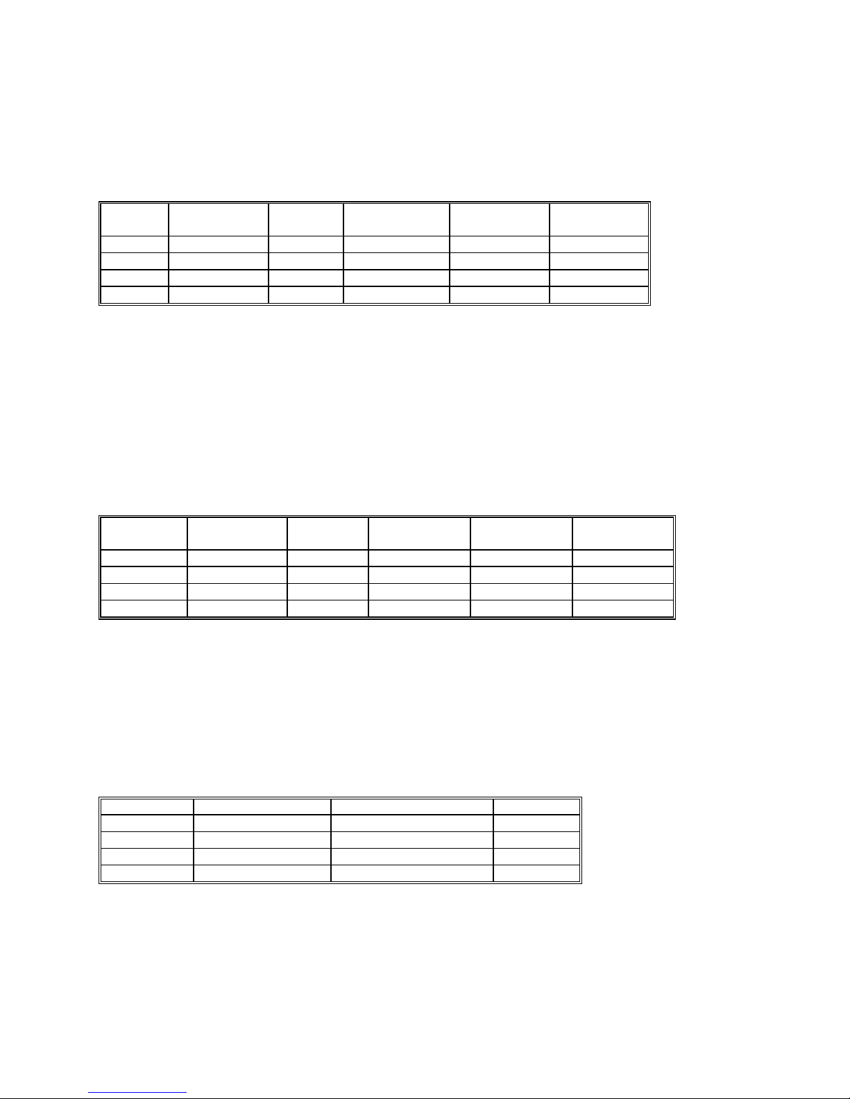
2.1 DC Voltage Measurement
Input Characteristics
• Input Resistance 330 mV & 3.3 V Ranges: >10 GΩ ,
• Input Resistance 33 V & 330 V Ranges: 10.0 MΩ
Accuracy ± (% of reading + Volts) [1]
Range Full Scale
6 ½ Digits
330 mV 330.0000 mV
3.3 V 3.300000 V
33 V 33.00000 V
330 V 330.0000 V
Resolution 24 hours
23°C ± 1°C
100 ηV 0.003 + 4.5 µV 0.004 + 5.5 µV 0.007 + 8 µV
1 µV 0.002 + 10 µV 0.0025 + 12 µV 0.0045 + 17 µV
10 µV 0.003 + 250 µV 0.004 + 280 µV 0.007 + 330 µV
100 µV
0.004 + 1 mV 0.005 + 1.2 mV 0.008 + 1.5 mV
90 Days
23°C ± 5°C
One Year 23°C
± 5°C
[1] With reading rate set to 10 readings per second (rps) or slower, and within one hour of DCV
zero, using Relative control.
DCV Noise Rejection Normal Mode Rejection, at 50, 60, or 400 Hz ± 0.5%, is better than 95 dB
for reading rates of 10 rps or lower. Common Mode Rejection (with 1 kΩ lead imbalance) is better
than 120 dB for these conditions.
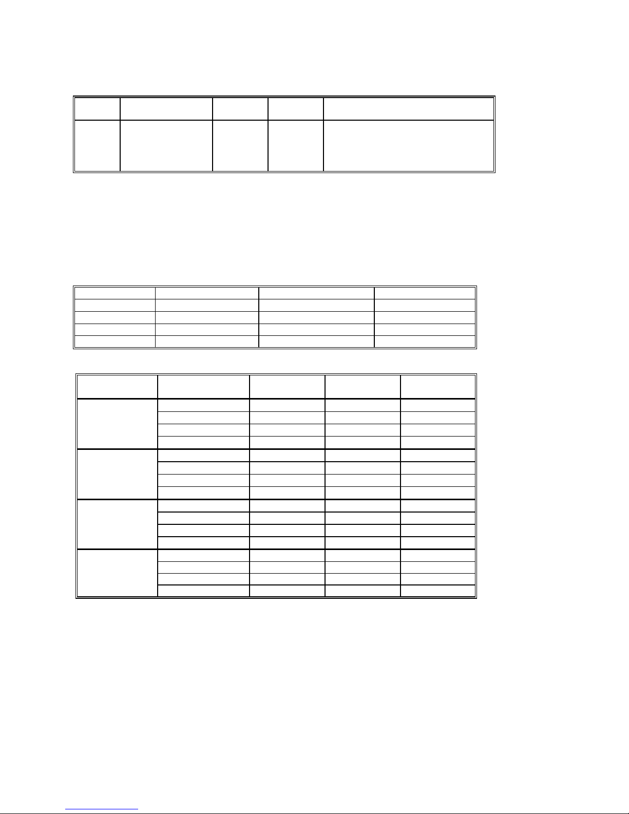
2.2 DC Current Measurement
Input Characteristics
• Burden Voltage < 350 mV for all ranges
• Protected with 2.5A fuse ( 5x20mm, 250 V Fast)
Accuracy ± (% of reading + Amps) [1]
Range Full Scale
5 ½ Digits
3.3 mA 3.30000 mA
33 mA 33.0000 mA
330 mA 330.000 mA
2.5 A 2.50000 A
Resolution 24 hours
23°C ± 5°C
10 ηA 0.052 + 200 ηA 0.07 + 350 ηA 0.1 + 400 ηA
100 ηA 0.04 + 1 µA 0.06 + 2 µA 0.1 + 3 µA
1 µA 0.05 + 30 µA 0.055 + 40 µA 0.075 + 60 µA
10 µA 0.55 + 50 µA 0.6 + 200 µA 0.65 + 350 µA
90 Days
23°C ± 5°C
One Year 23°C
± 5°C
[1] With reading rate set to 10 rps or slower, and within one hour of DCI zero, using Relative control.
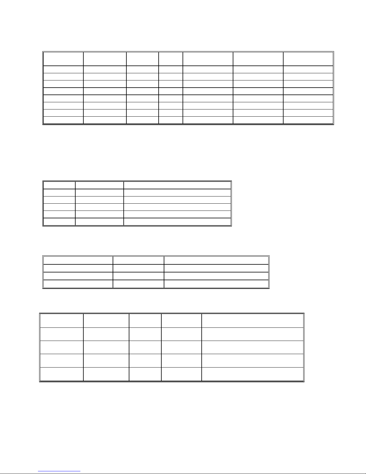
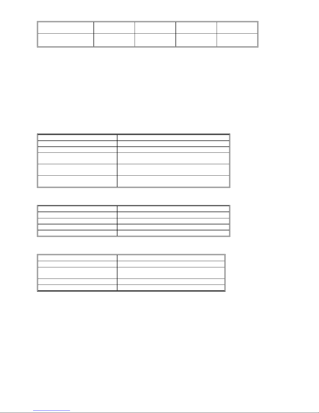
2.3 AC Voltage Measurements
Input Characteristics
• Input Resistance 1.0 MΩ, shunted by < 100 pF, all ranges
• Crest Factor 3 at Full Scale, increasing to 7 at Lowest Specified Voltage
• AC coupled Specified range: 10 Hz to 100 kHz
• Typical Settling time < 0.5 sec to within 0.1% of final value
2.3.1 AC Voltage True RMS Measurement
Range Full Scale 6 ½ Digits Lowest specified Voltage Resolution
330 mV 330.0000 mV 5 mV [1]
3.3 V 3.300000 V 10 mV
33 V 33.00000 V 100 mV
250 V [2] 250.0000 V 1 V
[1] Between 5 mV and 10 mV, add 100 µV additional error to the accuracy table below. In many
computer installations, if the DMM is not near a noisy board, usable voltage measurements of 1 mV
can be obtained.
6
[2] Signal is limited to 8x10
32 kHz, or 8x10
6
Volt x Hz.
Volt Hz Product. For example, the largest frequency input at 250 V is
9 Signametrics
100 ηV
1 µV
10 µV
100 µV
Artisan Technology Group - Quality Instrumentation ... Guaranteed | (888) 88-SOURCE | www.artisantg.com
Page 11

Accuracy ± (% of reading + Volts) [1]
Range Frequency 24 hours
23°C ± 1°C
330 mV
3.3 V
33 V
250 V
10 Hz - 20 Hz
20 Hz - 47 Hz
47 Hz - 10 kHz
10 kHz - 50 kHz
50 kHz - 100 kHz
10 Hz - 20 Hz 3.0 + 2 mV 3.1 + 2.2 mV 3.2 + 2.5 mV
20 Hz - 47 Hz 0.93 + 1.3 mV 0.96 + 1.5 mV 1.0 + 1.7 mV
47 Hz - 10 kHz 0.05 + 1 mV 0.055 + 1.1 mV 0.065 + 1.2 mV
10 kHz - 50 kHz 0.62 + 1.2 mV 0.65 + 1.3 mV 0.70 + 1.5 mV
50 kHz - 100 kHz 5.1 + 1.5 mV 5.2 + 1.7 mV 5.3 + 2 mV
10 Hz - 20 Hz 3.0 + 14 mV 3.1 + 16 mV 3.3 + 20 mV
20 Hz - 47 Hz 0.93 + 12 mV 0.96 + 14 mV 1.0 + 16 mV
47 Hz - 10 kHz 0.06 + 10 mV 0.065 + 11 mV 0.073 + 13 mV
10 kHz - 50 kHz 0.31 + 18 mV 0.33 + 21 mV 0.35 + 25 mV
50 kHz - 100 kHz 2.0 + 30 mV 2.2 + 35 mV 2.4 + 40 mV
10 Hz - 20 Hz 3.0 + 140 mV 3.1 + 160 mV 3.3 + 200 mV
20 Hz - 47 Hz 0.93 + 120 mV 0.96 + 130 mV 1.0 + 150 mV
47 Hz - 10 kHz 0.04 + 100 mV 0.045 + 110 mV 0.06 + 130 mV
10 kHz - 50 kHz 0.32 + 150 mV 0.4 + 170 mV 0.45 + 200 mV
50 kHz - 100 kHz 2.5 + 200 mV 2.8 + 240 mV 3.2 + 300 mV
3.0 + 350 µV 3.1 + 380 µV 3.2 + 430 µV
0.92 + 150 µV 0.93 + 170 µV 0.95 + 200 µV
0.13 + 100 µV 0.14 + 110 µV 0.15 + 120 µV
0.55 + 160 µV 0.6 + 200 µV 0.63 + 230 µV
5.3 + 350 µV 5.4 + 370 µV 5.6 + 400 µV
90 Days
23°C ± 5°C
One Year
23°C ± 5°C
ACV Noise Rejection Common Mode rejection, for 50 Hz or 60 Hz with 1 kΩ imbalance in either lead, is better
than 60 dB.
2.3.2 AC Peak-to-Peak Measurement (SMX2044)
• Measures the peak-to-peak value of a repetitive waveform
ACV
Range
330 mV 0.1 V 1.85 V 1 mV
3.3 V 1.0 V 18.5 V 10 mV 1.4 ±70 mV
33 V 10 V 185.0 V 100 mV 1.0 ±700 mV
250 V 100 V 850.0 V 1 V 1.0 ± 6 V
[1] Specified from 30Hz to 10 kHz. Input signal frequency of 30 Hz to 30 kHz.
Lowest specified
input voltage
(Vp-p)
Full Scale
reading (Vp-p)
Resolution
Typical Accuracy 23°C ± 5°C
One Year [1]
1.5 ±10 mV
2.3.3 AC Crest Factor Measurement (SMX2044)
•
Measures the crest factor (peak / RMS) of a repetitive waveform
ACV
Range
330 mV 0.1 V 1.8 V 0.01
3.3 V 1.0 V 18 V 0.01 2.1 ±0.1
33 V 10 V 180 V 0.01 2.0 ±0.1
250 V 100 V 700 V 0.01 2.0 ±0.1
[1] Crest factor measurement requires signal frequency of 30 Hz to 30 kHz.
Lowest specified
input voltage
(Vp-p)
Highest specified input
voltages (Vp-p)
Resolution
Typical Accuracy 23°C ± 5°C
One Year [1]
2.2 ±0.3
Signametrics 10
Artisan Technology Group - Quality Instrumentation ... Guaranteed | (888) 88-SOURCE | www.artisantg.com
Page 12
2.3.4 AC Median Value Measurement (SMX2044)
• Measures the mid-point between the positive and negativ e peaks of a repetitive waveform
• Used to determine the Threshold DAC setting for optimal frequency and timing measurements
ACV
Range
330 mV 0.08 V
3.3 V 0.80 V
33 V 8 V
250 V 80 V
[1] Median measurements require a repetitive signal with frequency range of 30 Hz to 30 KHz.
Lowest specified input
voltage (Vp-p)
Full Scale
reading
±0.95 V
±9.5 V
±95.0 V
±350.0 V
Resolution
1 mV
10 mV 3% ±160 mV
100 mV 3% ±1.4 V
1 V 3% ±12 V
Typical Accuracy 23°C ± 5°C One Year [1]
2.0% ±17 mV
2.4 AC Current Measurement, True RMS
Input Characteristics
• Burden Voltage < 350 mV RMS all Ranges
• Crest Factor 3 at Full Scale, increasing to 7 at Lowest Specified Current
•
Protected with 2.5 A fuse ( 5x20 mm, 250 V Fast)
Range Full Scale 6 1/2 Digits Lowest Specified Current Resolution
3.3 mA 3.300000 mA
33 mA 33.00000 mA
330 mA 330.0000 mA 5 mA 100 nA
2.5 A 2.500000 A 50 mA 1 uA
Accuracy ± (% of reading + Amps)
Range Frequency 24 hours
3.3 mA
33 mA
330 mA
2.5 A
10 Hz - 20 Hz
20 Hz - 47 Hz
47 Hz - 1 kHz
1 kHz - 10 kHz
10 Hz - 20 Hz
20 Hz - 47 Hz
47 Hz - 1 kHz
1 kHz - 10 kHz
10 Hz - 20 Hz
20 Hz - 47 Hz
47 Hz - 1 kHz
1 kHz - 10 kHz
10 Hz - 20 Hz 1.8 + 4 mA 2.5 + 4.5 mA 2.7 + 5 mA
20 Hz - 47 Hz 0.66 + 4 mA 0.8 + 6 mA 0.9 + 6 mA
47 Hz - 1 kHz 0.6 + 3.8mA 0.63 + 3.8 mA 0.65 + 4 mA
1 kHz - 10 kHz 0.6 + 4mA 0.62 + 4.5 mA 0.7 + 5 mA
Note: All AC Current ranges have typical measurement capability to 20 kHz.
50 µA
500 µA
23°C ± 1°C
3.8 + 4 µA 2.7 + 4 µA 2.9 + 4 µA
0.9 + 4 µA 0.9 + 4 µA 1.0 + 4 µA
0.04 + 1.5 µA 0.08 + 3 µA 0.12 + 4 µA
0.12 + 4 µA 0.14 + 4 µA 0.22 + 4 µA
1.8 + 30 µA 2.6 + 30 µA 2.8 + 30 µA
0.6 + 30 µA 0.9 + 30 µA 1.0 + 30 µA
0.07 + 10 µA 0.15 + 20 µA 0.16 + 30 µA
0.21 + 30 µA 0.3 + 40 µA 0.4 + 40 µA
1.8 + 400 µA 2.7 + 400 µA 2.8 + 400 µA
0.6 + 400 µA 0.9 + 400 µA 1.0 + 400 µA
0.1 + 100 µA 0.17 + 180 µA 0.22 + 220 µA
0.3 + 300 µA 0.4 + 350 µA 0.6 + 400 µA
90 Days
23°C ± 10°C
1 nA
10 nA
One Year
23°C ± 10°C
Artisan Technology Group - Quality Instrumentation ... Guaranteed | (888) 88-SOURCE | www.artisantg.com
11 Signametrics
Page 13
2.5 Resistance Measurements
2.5.1 2-wire and 4-wire
Accuracy ± (% of reading + Ω) [1]
Range [2] Full Scale
6 ½ Digits
33 Ω [3] 33.00000 Ω 10 µΩ
330 Ω 330.0000 Ω 100 µΩ
3.3 kΩ 3.300000 kΩ 1 mΩ
33 kΩ 33.00000 kΩ 10 mΩ 100 µA 0.0025 + 300 mΩ 0.0033 + 330 mΩ 0.006 + 350 mΩ
330 kΩ 330.0000 kΩ 100 mΩ 10 µA 0.0055 + 3.2 Ω 0.007 + 4 Ω 0.009 + 5 Ω
3.3 MΩ 3.300000 MΩ 1 Ω 1 µA 0.018 + 40 Ω 0.03 + 50 Ω 0.04 + 70 Ω
33 MΩ 33.0000 MΩ 100 Ω
330 MΩ [3] 330.00 MΩ 10 kΩ
Resolution Source
current
10 mA
1 mA
1 mA
100 nA
10 nA
24 hours
23°C ± 1°C
0.0038 + 1 mΩ 0.005 + 1.5 mΩ 0.008 + 2 mΩ
0.0037 + 4.5 mΩ 0.0046 + 5 mΩ 0.007 + 6 mΩ
0.0023 + 28 mΩ 0.003 + 32 mΩ 0.005 + 33 mΩ
0.12 + 400 Ω 0.13 + 500 Ω 0.2 + 600 Ω
1 + 50 kΩ 1.4 + 60 kΩ 2.0 + 80 kΩ
90 Days
23°C ± 10°C
One Year
23°C ± 10°C
[1] With reading rate set to 2 rps or slower, and within one hour of Ohms zero, using Relative control.
[2] 4-wire ohms is available up to the 330 kΩ range.
[3] 33 Ω and 330 MΩ ranges are only available with the SMX2042,44.
2.5.2 6-wire Guarded Resistance Measurement (SMX2044)
Typical additional error contributed by guarding
Range Source current
33 Ω
330 Ω
3.3 kΩ
33 kΩ 100 µA 0.03 + 1 Ω
330 kΩ 10 µA 0.35 + 10 Ω
10 mA
1 mA
1 mA
Accuracy ± (% of reading + Ω)
One Year 23°C ± 5°C [1]
0.3 + 4 mΩ
0.003 + 20 mΩ
0.005 + 100 mΩ
[1] This table should be used in conjunction with the 2-wire and 4-wire table above.
2.6 Leakage Measurement (SMX2044)
Accuracy ± (% of reading + Ω) [1]
Leakage Reading Voltage range
1.00 ηA to 100.00 ηA
100.00 ηA to 1000.00ηA
1000.00 ηA to 3.3 µA
-10 V to +10 V 2 + 350 pA
-9 V to + 9 V
-7 V to + 7 V
One Year 23°C ± 5°C [1]
1.2 + 2 ηA
1.5 + 20 ηA
[1] Error does not include external shunt resistor’s tolerance.
2.7 RTD Temperature Measurement (SMX2044)
RTD Type
pt385, pt3911,
pt3916, pt3926
pt385, pt3911,
pt3916, pt3926
Cu (Copper)
Cu (Copper)
Ro (Ω)
100, 200 Ω 0.01°C -150 to 650°C ±0.06°C
500, 1 kΩ 0.01°C -150 to 650°C ±0.03°C
Less than 12 Ω 0.01°C -100 to 200°C ±0.18°C for temperatures ≤ 20°C, ±0.05°C
Higher than 90 Ω 0.01°C -100 to 200°C ±0.10°C for temperatures ≤ 20°C, ±0.05°C
[1] With reading rate set to 2 rps or slower, using a 4-wire RTD. Measurement accuracy does not
include RTD probe error.
Resolution Temperature
range
Temperature Accuracy 23°C ± 5°C [1]
One Year
otherwise
otherwise
Signametrics 12
Artisan Technology Group - Quality Instrumentation ... Guaranteed | (888) 88-SOURCE | www.artisantg.com
Page 14

2.8 Additional Component Measurements
2.8.1 Diode Characterization
• Available DC current values 100 ηA, 1 µA, 10 µA, 100 µA and 1 mA. SMX2042 and SMX2044 add 10
mA. SMX2044 has a variable current from 10 ηA to 12.5 mA using the DCI source.
• Typical Current Value Uncertainty 1%
• Typical Voltage Value Uncertainty 0.02%
•
Maximum diode voltage compliance 4 V
2.8.2 Capacitance Measurement (SMX2042, 44)
Accuracy ± (% of reading + Farads) [1]
Range Full Scale
4 ½ Digits
10 ηF 11.999 ηF
100 ηF 119.99 ηF
1 µF 1.1999 µF
10 µF 11.999 µF 1 ηF
100 µF 119.99 µF 10 ηF
1 mF 1.1999 mF
10 mF 11.999 mF
Resolution One Year
23°C ± 5°C
1 pF 2.1 ± 5 pF
10 pF 1.0
100 pF 1.0
100 ηF
1 µF
1.0
1.0
1.2
2
[1] Within one hour of zero, using Relative control. Accuracy is specified for values higher than 5% of the selected
range with the exception of the 10 ηF range, which measures down to 0 pF.
2.8.3 Inductance Measurement (SMX2044)
± (% of reading + inductance) [1]
Range Default
frequency
33 µH
330 µH
3.3 mH 4 kHz 3.3000 mH
33 mH 1.5 kHz 33.000 mH
330 mH 1 kHz 330.00 mH
3.3 H 100 Hz 3.3000 H
75 kHz
50 kHz
Full Scale
4 ½ Digits
33.000 µH 1 ηH 3.0% + 500 ηH
330.00 µH 10 ηH 2.0% + 3 µH
Resolution
100 ηH 1.5% + 25 µH
1 µH 1.5% + 200 µH
10 µH
100 µH
Accuracy 23°C ± 5°C
One Year [2]
2.5 + 3 mH
3 + 35 mH
[1] Within one hour of zero, and Open Terminal Calibration.
[2] Accuracy is specified for values greater than 5% of the selected range.
2.8.4 In Circuit AC-Based Capacitance Measurements (SM2044)
Accuracy ± (% of reading + Farads) [1]
Range Full Scale
4 ½ Digits
33 ηF 32.99 ηF
330 ηF 329.9 ηF
3.3 µF 3.299 µF
33 µF 32.99 µF 10 ηF 5% ± 20 ηF
330 µF 329.9 µF 100 ηF 5% ± 1 µF
3.3 mF 3.299 mF
[1] Specified to 2/3 of range (ie. 22ηF on 33nF range). Within one hour from last AC-Caps Open calibration. Add
an error of 50e-6*R*C (%) due to paralled resistance.
Resolution One Year
23°C ± 5°C
10 pF 12% ± 250 pF
100 pF 5% ± 500 pF
1000 pF
1 µF 7% ± 50 µF
4% ± 1 ηF
Artisan Technology Group - Quality Instrumentation ... Guaranteed | (888) 88-SOURCE | www.artisantg.com
13 Signametrics
Page 15

2.9 Timing Measurements (SMX2042, 44)
2.9.1 Threshold DAC
• The Threshold DAC is used for selecting a detection threshold to give optimal frequency and
timing measurements.
± (% of setting + volts)
Selected VAC
range [1]
330 mV -1.0 V to +1.0 V 0.5 mV 1.900 V 0.2% + 4 mV
3.3 V -10.0 V to +10.0 V 5.0 mV 19.00 V 0.2% + 40 mV
33 V -100.0 V to 100.0 V 50 mV 190.0 V 0.2% + 0.4 V
250 V -500 V to 500 V 500 V 850.0 V 0.2% + 4 V
Threshold range (DC
level)
Threshold
DAC
resolution
Highest allowed input
Vp-p
Typical one year setting
uncertainty
[1] This table should be used in conjunction with the AC volts section above.
2.9.2 Frequency and Period Measurement
ACV Mode
•
Input Impedance 1 MΩ with < 300 pF
Frequency Range 1 Hz - 100 Hz 100 Hz-1 kHz 1 kHz-10 kHz 10 kHz-100 kHz 100 kHz-300 kHz
Resolution 1 mHz 10 mHz 100 mHz 1 Hz 1 Hz
Uncertainty is ±0.002% of
reading ± adder shown
Input Signal Range [1] 10% - 200%
4 mHz 20 mHz 200 mHz 2 Hz 5 Hz
of range
10% - 200%
of range
10% -200%
of range
10% - 200%
of range
45% -200%
of range
[
1] Input RMS voltage required for a valid reading. Do not exceed 250 V RMS input. For example, 10% -200%
of range indicates that in the 330 mVAC range, the input voltage should be 33 mV to 660 mV RMS.
ACI Mode
•
Input Impedance 10 Ω in the 3 mA and 30 mA ranges, 0.1 Ω in the 330 mA and 2.5 A ranges.
Frequency Range 1 Hz - 100 Hz 100 Hz-1 kHz 1 kHz-10 kHz 10 kHz-500 kHz
Resolution 1 mHz 10 mHz 100 mHz 1 Hz
Uncertainty 0.01% ±4 mHz 0.01% ±20 mHz 0.01% ±200 mHz 0.01% ±2 Hz
Input Signal Range,
3.3 mA, 330mA Ranges
[1]
Input Signal Range,
33 mA, 2.5A ranges
[1] Input current required to give a valid reading. For example, 10% -500% of range indicates that in the 3.3 mA
range, the input current should be 0.33 mA to 16.5 mA.
10% -500%
of range
50% -100%
of range
10% - 500%
of range
50% - 100%
of range
10% -500%
of range
50% - 100%
of range
10% - 500%
50% - 100%
of range
of range
2.9.3 Duty Cycle Measurement
Frequency Range 1 Hz to 100 Hz 100 Hz to 1 kHz 1 kHz to 10 kHz 10 kHz to 100 kHz
Resolution 0.02% 0.2% 2% 20%
Typical Uncertainty is
±0.03% of reading ±
adder shown
Full scale reading 100.00 % 100.00 % 100.00 % 100.00 %
0.03% 0.3% 3% 20%
2.9.4 Pulse Width
Signametrics 14
Artisan Technology Group - Quality Instrumentation ... Guaranteed | (888) 88-SOURCE | www.artisantg.com
± (% of reading + sec)
Page 16
Polarity Frequency range Resolution Width range Typical
Uncertainty
Positive or negative pulse
widths
1 Hz to 100 kHz
2 µs 2 µs to 1 s 0.01 +/- 4 µs
2.9.5 Totalizer
• Active edge polarity: Positive or negative transition
• Maximum count: 10^9
•
Allowed rate: 1 to 30,000 events per second
Uses Threshold DAC
•
2.10 Trigger Functions
2.10.1 External Hardware Trigger (at DIN-7 connector)
Trigger Input voltage level range High: +3V to +15V, Low: -15V to +0.8V
Ttrigger High current drive Min. 1mA, Max 10mA (TTL or CMOS logic level)
Timing Characteristics Trigger occurs within 2/Reading rate
Trigger Activation Positive or Negative edge depending on trigger
command.
Internal Reading Buffer Up to 1,000 readings/sec into 64 locations reading buffer
Isolation of trigger input ±50 V from analog DMM inputs, and from computer
chassis earth ground.
2.10.2 PXI Bus Hardware Trigger Inputs (at PXI J2)
Trigger Input TTL or CMOS positive pulse
Trigger Pulse Width
Internal Reading Buffer up to 1,000 readings/sec into 64 readings buffer
Selectable lines PXI_TRIG1,2,3,4,5,6,7 and PXI_STAR
Isolation from DMM inputs ±330 V from any of the DMM 4 main inputs terminals
Minimum 250µS
2.10.3 PXI Bus Hardware Trigger Output (to PXI J2)
Trigger Output TTL or CMOS negative pulse. Positive edge = ready
Trigger Pulse Width
Activity A single pulse is issued for each A/D conversion (at 10
Selectable lines PXI_TRIG1,2,3,4,5,6 and PXI_STAR
Isolation from DMM inputs ±330 V from any of the DMM 4 main inputs terminals
Approximately 140µS
or higher measurement rate)
2.10.4 Analog Threshold Trigger
• Captures up to 64 readings
•
Reading rate: 10 rps or higher
Artisan Technology Group - Quality Instrumentation ... Guaranteed | (888) 88-SOURCE | www.artisantg.com
15 Signametrics
Page 17
2.11 Source Functions (SMX2044)
• Isolated to 300 V DC from the Chassis
• Current can be paralleled with multiple SMX2044s
•
Voltage can be put in series with multiple SMX2044s
2.11.1 DC Voltage Source
Parameter Closed Loop [1] Open Loop
Output Voltage range -10.000 V to +10.000 V
Typical Current source/sink at 5V output 5 mA 5 mA
DAC resolution 18 bits 12 bits
Accuracy 23°C ± 10°C One Year 0.015% ± 350 µV
Typical settling time 3 S (rate set to 2/s) 1 mS
Typical source resistance
250 Ω
1.0% ± 35 mV
[1] 10 rps or lower measurement rate is required for the closed loop mode.
2.11.2 AC Voltage Source
Parameter Closed Loop [1] Open Loop
Output Voltage, sine wave 50mV to 7.1 V RMS (0.14 to 20.0V peak-to-peak)
DAC resolution 16 bits 12 bits
Typical Current Drive at 3.5V RMS 3.5 mA RMS
Accuracy 18°C to 28°C One Year
Typical settling time (f-out > 40 Hz) 10 s (rate set to 2 rps) 1.5 s
Typical source resistance
Frequency range / resolution 2 Hz to 75 kHz / 2 Hz
Frequency stability 100 ppm ± 1 Hz
[1] 5 rps or lower measurement rate is required for the closed loop mode.
ACV spec ± 2 mV ACV spec + 0.8% ± 20 mV
250 Ω
2.11.3 DC Current Source
Range Compliance Voltage Resolution [1] Minimum level
1.25 µA
12.5 µA
125 µA
1.25 mA 4.2 V
12.5 mA 1.5 V
4.2 V 500 pA
4.2 V
4.2 V
5 ηA 10 ηA 1% + 100 ηA
50 ηA 100 ηA 1% + 500 ηA
500 ηA 1 µA 1% + 5 µA
5 µA 10 µA 1% + 50 µA
1 ηA 1% + 10 ηA
[1] Resolution without Trim DAC. The use of the Trim DAC can improve the resolution by a factor of 10, but it has
to be set separately since it is not calibrated.
Accuracy 23°C ± 10°C One Year
Signametrics 16
Artisan Technology Group - Quality Instrumentation ... Guaranteed | (888) 88-SOURCE | www.artisantg.com
Page 18

2.12 Accuracy Notes
Important All accuracy specifications for DCV, Resistance, DCI, ACV, and ACI apply for the time periods shown
in the respective specification tables. To meet these specifications, the System Calibration function must be
performed once a day. System Calibration is a simple software operation that takes a few seconds. Do it by
executing the DMMCalibrate() command, or selecting S-Cal in the control panel.
All three products are capable of continuous measurement as well as data transfer rates of up to 1,000 readings per
second (rps). To achieve the 6-1/2 digit resolution, the DMM should be operated at 5 rps or slower. The maximum
reading rate for 5-1/2 digits is 30 rps.
Accuracy vs. Reading Rates All of the above specifications apply to reading rates of 2 rps or lower. For higher
reading rates, increase the noise floor for DCV, Resistance, and DCI by the square root of the increase in reading
rate from 2 rps. For example, the noise floor for the 3.3 VDC range is 8 µV at 5 rps. At 20 readings per second, or
10x the reading rate, the noise increases by the square root of 10, or 3.16 times. The noise, then, at 20 readings per
second is ± 25 µV.
The noise characteristics for the AC functions increases by the same number as the DC functions. For example, the
noise floor for the 3.3 VAC, 20 rps, will have digit rattle of 8.7 mV vs. 2.75 mV at 2 rps.
Reading Rates vs. Noise Rejection The best AC (50 Hz, 60 Hz or 400 Hz) power line rejection is obtained at
reading rates that are whole number divisions greater than 1 of the line frequency, as shown in the following table.
For best AC line rejection you should use the reading rates checked. It is important to follow this table. Always use
the lowest checked rate that is practical for the application.
Reading Rate (rps) Power Line frequency
50 Hz 60 Hz 400 Hz
0.1
0.2
0.5
1
2
5
10
15 √
20
25
30 √
40
50
60 √
80
100
200
400
√ √ √
√ √ √
√ √ √
√ √ √
√ √ √
√ √ √
√ √ √
√ √
√
√
√
√
√
√
√
√
√
Reading Rates vs. Digits of Resolution For reading rates of 10 readings per second (rps) and slower, the DMM
has 6 ½ digits of resolution. For reading rates from 10 rps to 30 rps, the DMM has 5 ½ digits of resolution.
Artisan Technology Group - Quality Instrumentation ... Guaranteed | (888) 88-SOURCE | www.artisantg.com
17 Signametrics
Page 19

2.13 Other Specifications
Temperature Coefficient, All Functions Less than 0.1 x accuracy specification per °C
at
Reading Rate
• Up to 10 rps, 6 ½ digits
• Up to 30 rps, 5 ½ digits
Hardware Interface Single 3U PXI or CompactPCI slot
Overload Protection (voltage inputs) 330 VDC, 250 VAC
Isolation 330 VDC, 250 VAC from Earth Ground
Maximum Input (Volt x Hertz) 8x10⁶ Volt x Hz normal mode input (across Voltage HI &
1x10⁶ Volt x Hz Common Mode input (from Voltage HI or
Safety Designed to IEC 1010-1, Installation Category II.
Calibration Calibrations are performed by Signametrics in a computer
Temperature Range -10°C to 70°C, operating
-65°C to +85°C, storage
Size
DMM Internal Temperature ±2°C
Measurement (SMX2042, 44)
Power +5 volts, 300 mA maximum
Note: Signametrics reserves the right to make changes in materials, specifications, product functionality, or
accessories without notice.
(user selectable)
• 0.5 to 1,000 readings per second (rps)
23C ± 5°C
LO).
LO relative to Earth Ground).
with a 3°C internal temperature rise. All calibration constants
are stored in a text file.
7” X 3.5” (Standard PXI/CompactPCI 3U format)
Accessories
Several accessories are available for the SMX2040 DMMs, which can be purchased directly from Signametrics, or
one of its approved distributors or representatives. These are some of the accessrories avaialble:
• DMM probes SM-PRB ($15.70)
• DMM probe kit SM-PRK ($38.50)
• Delux probe kit SM-PRD ($95.00).
• Shielded SMT Tweezer Probes SM-PRSMT ($24.90).
• Multi Stacking Double Banana shielded cable 36” SM-CBL36 ($39.00).
• Multi Stacking Double Banana shielded cable 48” SM-CBL48 ($43.00).
• Mini DIN Trigger, 6-Wire Ohms connector SM2040-CON7 ($14.00).
• LabView VI’s library SM204x.llb ($99.00).
Signametrics 18
Artisan Technology Group - Quality Instrumentation ... Guaranteed | (888) 88-SOURCE | www.artisantg.com
Page 20

3.0 Getting Started
After unpacking the DMM, please inspect for any shipping damage that may have occurred, and report any claims
to your transportation carrier.
The DMM is shipped with the Digital Multimeter module; three floppy disks containing the various software panels
and drivers plus the calibration data specific for the unit, and this Operator's manual.
3.1 Setting the DMM
The SMX2040 series DMMs are PXI/CompactPCI Plug&Play devices and do not require any switch settings, or
any other adjustments to the DMM prior to installation. The on ly sw itches are the PXI trigger input and output
selection switches, capable of selecting one of the PXI triggers and PXI Start Trigger.
The SM40CAL.DAT file supplied with your DMM has a unique calibration record for that DMM (See
"Calibration" at the end of this manual.) When using multiple DMMs in the same chassis, the SM40CAL.DAT
file must have a calibration record for each DMM. Append the unique calibration records of each DMM into one
SM40CAL.DAT file using a text editor such as Notepad. The defalut location for the SM40CAL.DAT file is at
the root directory C:\.
3.2 Installing the DMM Module
Warning
To avoid shock hazard, install the DMM only into a chassis that has its power line connector connected to an
AC receptacle with an Earth Safety ground.
After installation, check to see that no loose wires or ribbon cables infringe upon any of the internal circuits
of the DMM, as this may apply measurement voltages to your chassis, causing personal injury and/or
damage to your equipment!
This module is designed for 3U PXI and CompactPCI chassis. To prevent shock hazard do not plug it into
other format chassis such as 6U without making shure that all sides of the DMM are covered.
Caution: Only install the DMM module with the power to the chassis turned OFF!
Use extreme care when plugging the DMM module(s) into a PXI or CompactPCI chassis. If possible, choose an
empty slot away from any high-speed boards (e.g. CPU or other noisy modules) or the power supply. Please be
patient during the installation process! Due to it’s shielding it is a tight fit. Watch for any interference b etween
the module and the chassis. Gently push the DMM into the chassis, making shure the handle is correctly located.
Once in, lock it in with the handle and tighten th e top and bottom screws to secure it into the chassis. Be patient!
3.3 Installing the DMM software package
To install the DMM, turn off the PXI/CompactPCI chassis, plug in the DMM into the PXI/CompcatPCI chassis,
preferably away from the CPU or any other noisy card, than turn on the power. The first time you power up your
computer with the DMM installed, your Windows system will detect the new DMM and will open the “New
Hardware found” wizard. It will prompt you for a driver. Insert Disk1 which contains the necessary driver.
To complete the installation, run the ‘SETUP’ program provided on the Diks1. This takes care of all installation
and registration requirements of the software. If you are installing the DMM on a computer that had an SMX2040
series install in it, you should first uninstall the old software. For a clean reintallation remove all INF files
containing reference to the Signametrics DMM. Dependig on operatin g system, these files will be located at
Windows\inf, Windows\inf\other or WINNT\inf. The files will be named Oemx.INF where x is 0,1,2,… and/or
SIGNAMETRICSSMX2040.INF. If present, these files will prevent “Found New Hardware” wizard from
detecting the new DMM. Also, make sure you backup and remove the old calibration record (C:\SM40CAL.DAT).
3.4 DMM Input Connectors
Artisan Technology Group - Quality Instrumentation ... Guaranteed | (888) 88-SOURCE | www.artisantg.com
19 Signametrics
Page 21
Before using the DMM, please take a few moments and review this section to understand where the voltage,
current, or resistance and other inputs and outputs should be applied. This section contains important information
concerning voltage and current limits. Do not exceed these limits, as personal injury or damage to the
instrument, your chassis or application may result.
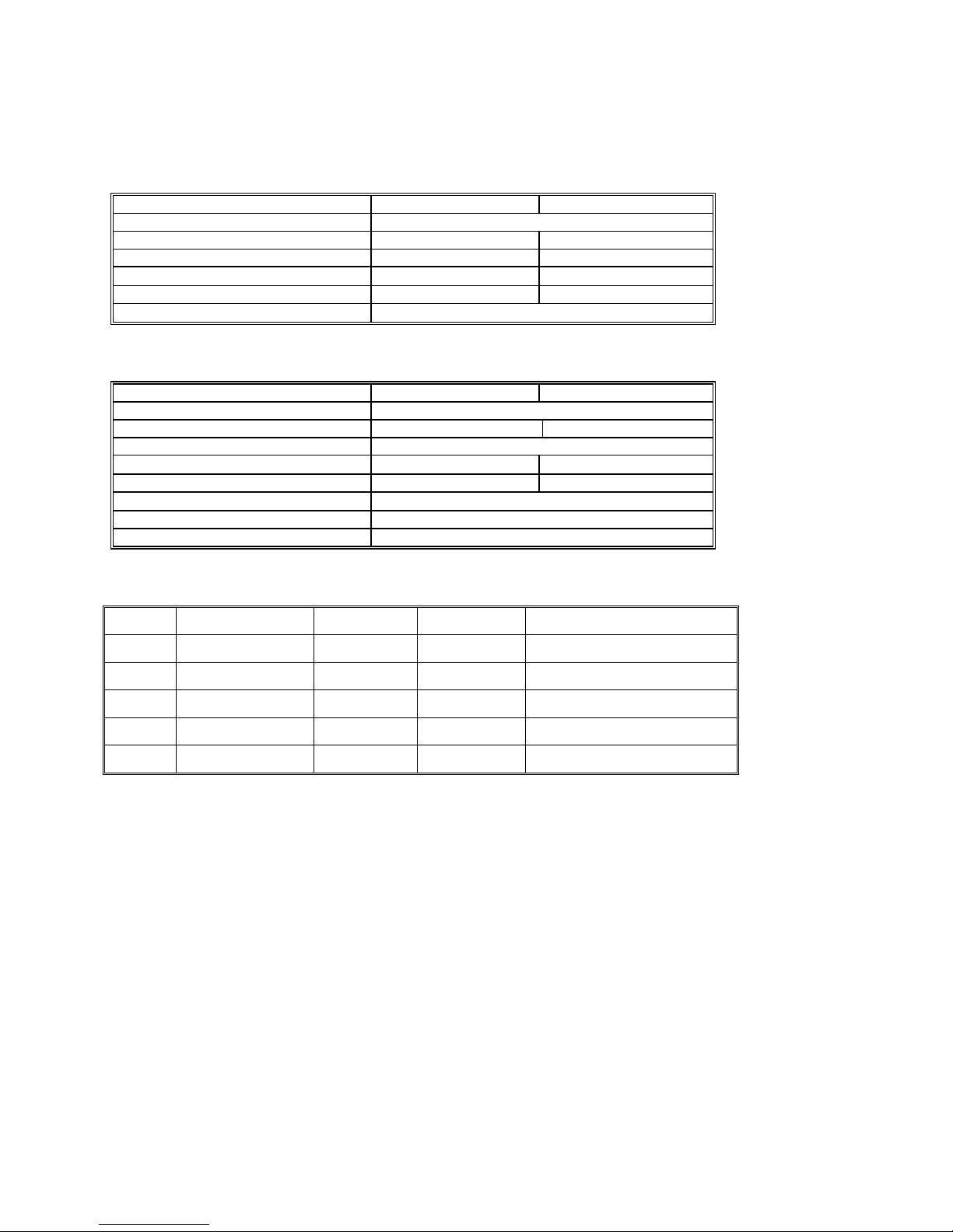
F input con
igure 3-1. The DMM nectors.
V + This is the positive termin ode and inductance measurements, and for
, Ω al for all Volts, 2WΩ, capacitance, di
sourcing of VDC, VAC and IDC. ents. The maximum input across V, Ω
+ and V, Ω - is 300 VDC or 250 V ode. When in the sourcing mode, the maximum
ed before damage occ
urs is 100 volts. input allow
WΩ measuremIt is also the Source HI for 4
mAC when in the measuring
V, Ω - This is the negative terminal for all Volts, 2WΩ, capacitance diode and inductance measurements, and or
sourcing of VDC, VAC and IDC. It is also the Source LO for 4WΩ. Do not float this terminal or any other
DMM terminal more than 300 VDC or 250 VAC above Earth Ground. (Also, see Trig, 6W Guard below.)
I + This is the positive terminal for all Current measurements. It is also the Sense HI for 4WΩ measurements and
6WΩ guarded measurements. The maximum input across I, 4WΩ + and I, 4WΩ - is 2.5 A. Do not apply more than
5 V peak across these two terminals!
I – This is the negative terminal for all Current measurements. In the Current modes, it is protected with a 2.5 A,
250 V Fast Blow fuse (5 x 20 mm). It is also the Sense LO for 4WΩ measurements and 6WΩ guarded
measurements. V, Ω - and I, 4WΩ - should never have more than 5 V peak across them.
TRIG GUARD Both the Trigger and Guard functions use the DIN-7 connector. This group of pins include the
positive and negative hardware trigger input lines and the two SMX2044 Guarded Measurement Force and Sense
signals. The external trigger initiates reading(s) into the onboard buffer, and the 6W guard signals facilitate in-
Signametrics 20
Artisan Technology Group - Quality Instrumentation ... Guaranteed | (888) 88-SOURCE | www.artisantg.com
Page 22
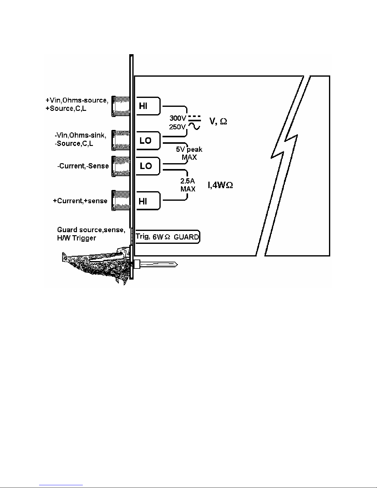
circuit resistor measurements by means of isolating a loading node. The DIN-7 plug can be ordered from
Signametrics and is available at many electronic hardware distributors. The connector is generically referred to as a
mini DIN-7 male. The trigger signal should be in the range of 3 V to 12 V peak. The two 6W guard signals should
never have more than 5 V peak across them.
Warning! The DIN connector pins are protected to a maximum of 35 V with respect to the chassis and any
other DMM terminal. Do not apply any voltages greater than 35 V to the DIN connector pins. Violating this
limit may result in personal injury and/or permanent damage to the DMM.
DIN-7, Pin number Function
7 External Trigger, Positive terminal
4 External Trigger, Negative terminal
1 Guard Source (SMX2044)
6 Guard Sense (SMX2044)
DIN-7 Connector Pin Description, view from bracket side.
.5 Starting the Control Panel 3
You can verify the installation and gain familiarity with the DMM by exercising its measurement functions using
the Windows based Control Panel. To run the control panel, double click the “SMX2044.EXE”. If you do not hear
the relays click, it is most likely due to an installation error. Another possible sour ce for an error is that the
SM40CAL.DAT file does not correspond to the installed DMM.
The Control Panel is operated with a mouse. All functions are accessed using the left mouse button. When the
DMM is operated at very slow reading rates, you may have to hold down the left mouse button longer than usual for
the program to acknowledge the mouse click.
Note: The SMX2040 front panel powers up in DCV, 2 readings per second, 330 V range. If the DMM is operated in
Autorange, with an open input, you may hear the SMX2040 relays clicking every few seconds, as a range change
occurs. This is perfectly normal with ultra high impedance DMMs such as the SMX2040. This phenomenon is
caused by the virtually infinite input impedance of the 330 mV and 3.3 V DCV ranges. On these ranges, an open
input will read whatever charge is associated with the signal conditioning of the DMM. As this electrical charge
changes, the SMX2040 will change ranges, causing the relay clicking. This is normal.
Artisan Technology Group - Quality Instrumentation ... Guaranteed | (888) 88-SOURCE | www.artisantg.com
21 Signametrics
Page 23

3.6 Using the Control Panel
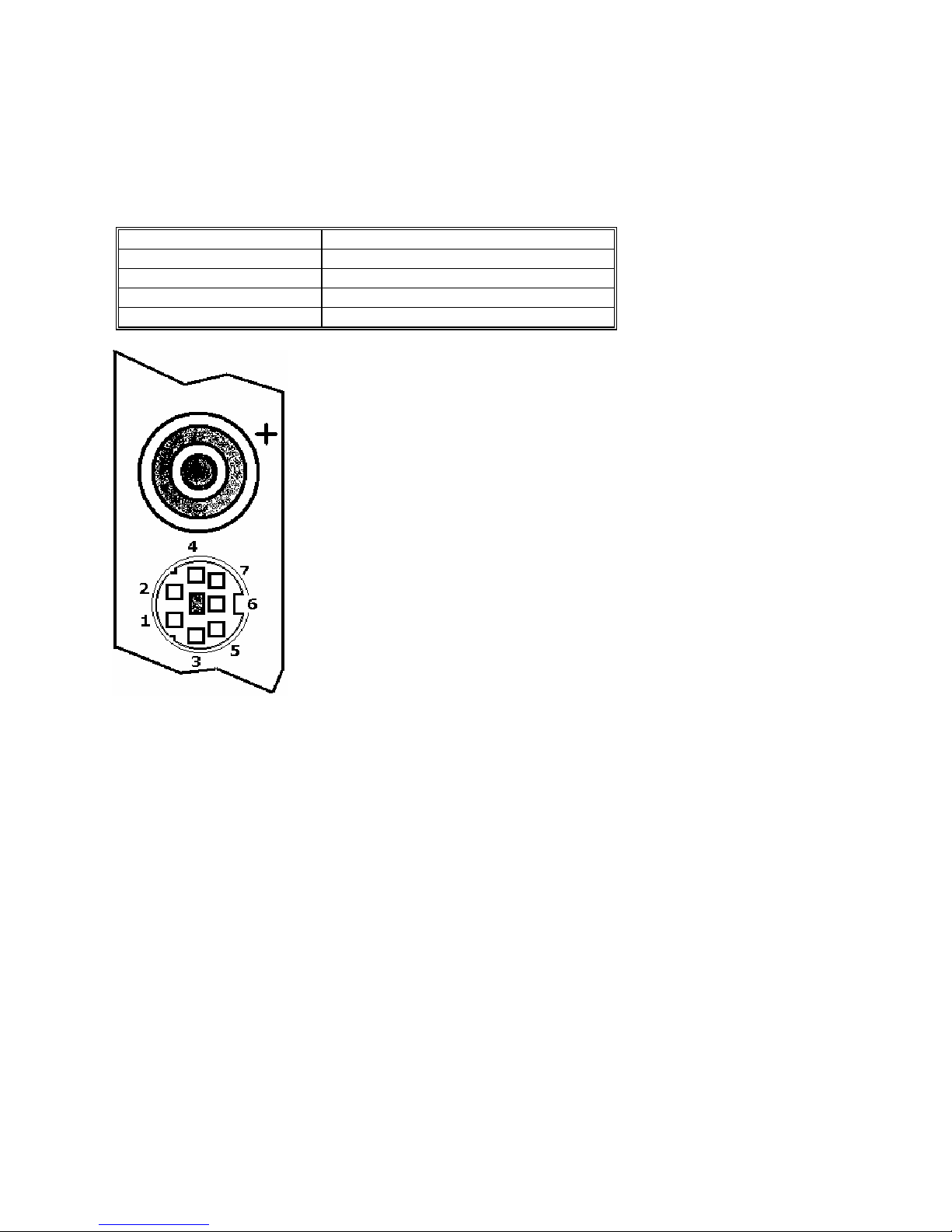
Figure 3-2. The Control Panel for the SMX2044. The three main groups include Measure, Source and
ange buttons. The 8 Range buttons are context sensitive such that only “330m, 3.3, 33 and 250 appear R
when in AC Voltage Functions, “3.3m 33m 330m 2.5” appear when in Current Functions, etc.
Note: All of the controls described below correspond to their respective software function, which can be invoked
within your control software or as objects in a visual programming environment. Using the software command
language of the SMX2040 provides powerful capabilities. Some composite functions are not included in the control
panel above.
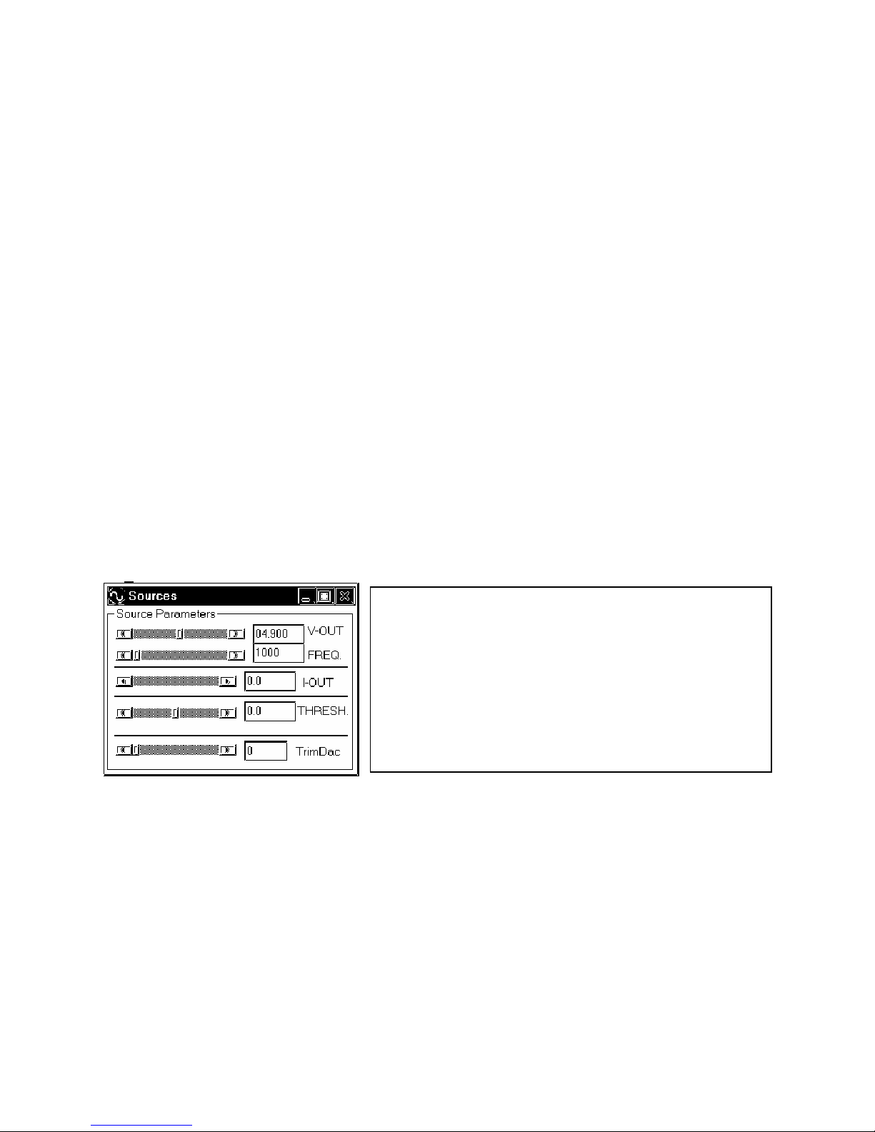
DC/AC This function switches between DC and AC. This is applicable for the following DMM functions:
Voltage, Current, and Voltage-Source. If Voltage-Source is the function presently in use, the Source control under
the Tools menu can be used to set frequency and amplitude in ACV, and amplitude only in DCV and DCI.
Relative This is the Relative function. When activated, the last reading is stored and subtracted from all
subsequent readings. This is a very important function when making low level DCV measurements, or in 2WΩ. For
example, when using 2WΩ, you can null out lead resistance by shorting the leads together and clicking on Relative.
When making low level DC voltage measurements (e.g., in the µV region), first apply a copper short to the V,Ω +
& - input terminals, allow the reading to stabilize for a few seconds, and click on Relative. This will correct for any
offsets internal to the SMX2040. The Relative button can also be used in the Percent and dB deviation displays
hown below), which are activated using the
(s
The Min/Max box can be used to analyze variations in terms of Min, Max, Percent and
dBV. This display can be activated by selecting the
menue. For instance, testing a circuit bandwidth with an input of 1V RMS, activate t
Relative function with the frequency set to 100Hz, than sweep gradually the frequency
and monitor the percent deviation as well as the dBV error and capture any response
anomalies with the Min/Max display. The left display indicates peaking of 2.468%
(0.21 dBV) and maximum
10.79mV from the reference at 100Hz.
Tools in the top menu.
Min/Max/Deviation from the Tools
he
,
peaking in the response of +56.24mV and a notch of –
Rate Box Controls the SMX2040 reading rate. 0.1 rps to 1,000 rps can be set. As measurement rate increases, so
does the measurement noise. For best accuracy set to the lowest rate acceptable for the application. Also consider
the line frequency (50/60 Hz) of operation when setting reading rates, as certain reading rates have more noise
rejection at either 50 or 60 Hz. (See “Specifications” for details.) Generally, set the measurement rate to as low a
rate as practical for the application. When measuring RMS values, th ere is no point setting the measurement rate to
a value higher than 5 rps since the RMS circuitry has a settling time that is over a second. The capacitance and
inductance functions are not affected by rate setting.
Note on Measurement Rate: All three products are capable of continuous measurement as well as data transfer
rates of up to 1,000 rps. To achieve the 6-1/2 digit resolution and accuracy, the DMM should be operated at 10 rps
or slower. The maximum reading rate for 5-1/2 digits is 30 rps.
Signametrics 22
Artisan Technology Group - Quality Instrumentation ... Guaranteed | (888) 88-SOURCE | www.artisantg.com
Page 24
Range Can be set to AutoRange or manual by clicking on the appropriate range in the lower part of the Windows
pprop
panel. Autoranging is best used for bench top application and is not recommended for an automated test
application due to the uncertainty of the DMM ran ge, as well as the extra time for range changes. Locking a range is
highly recommended when operating in an automated test system, especially to speed up measurements. Another
reason to lock a range is to control the input impedance in DCV. The 330 mV and 3.3 V ranges have virtually
infinite input impedance, while the 33 V and 330 V ranges have 10 MΩ input impedance.
S_Cal This function is the System Calibration that corrects for internal gain, scale factor and zero errors. The
DMM does this by alternatively selecting its local DC reference and a zero input. It is required at least once every
day to meet the SMX2040 accuracy specifications. We recommend that you also perform this function whenever
the external environment changes (e.g. the temperature in your work environment changes by more than 5°C, or the
SMX2044 on board temperature sensor indicates more than a 5°C change). This function takes less than a few
seconds to perform. Disconnect all leads to the DMM before doing this operation. Keep in mind that this is not a
substitute for periodic calibration, which must be performed with external standards.
ClosedLoop This check box selection is used in conjunction with the AC and DC Voltage-Source functions of the
SMX2044. When checked, the DMM monitors the output level and continuously applies corrections to the output
level. When not checked, the DMM is a 12 bit source vs. 16 bits in the ClosedLoop mode.
OpenCal This check box selection is used in conjunction with inductance measurement. It is necessary to perform
Open Terminal Calibration using this control, prior to measuring inductance. This function characterizes both the
internal DMM circuitry as well as the probe cables. To perform OpenCal, attach the probe cables to the DMM,
leaving the other end of the probe cables open circuited. Then, activate the OpenCal button.
Sync With this check box selection is active, the DMM measurements are internally synchronized, which reduces
the measurement rate, but allows full scale input swings to be settled in single measurement.
Sources Panel There are three function buttons in the Source group (SMX2044 only). The V, I, LEAK buttons
select one of three source functions, Voltage (DC and AC), IDC and Leakage. The Sources Panel is automatically
enabled when one of the source functions is enabled. It can also be invoked using the Sources Panel selection under
the
Tools menu. This panel allows the entry of values for all of the source functions, including Leakage.
The V-OUT Scroll bar and Text box are used to set
the Voltage for DC and AC Volts as well as for
Leakage. When sourcing ACV, the voltage is in RMS
and the FREQ. Scroll bar and Text box control the
frequency of the source. It is also used to control
inductance frequency. When sourcing DC current, use
the I-OUT set of controls. When measuring timing or
freqeuncy the THRESH set of controls is used for
comperator threshold. All of the source controls are
context sensitive and will be enabled when
riate.
a
Artisan Technology Group - Quality Instrumentation ... Guaranteed | (888) 88-SOURCE | www.artisantg.com
23 Signametrics
Page 25

4.0 DMM Operations and Measurements
Most of the SMX2040 measurement functions are accessible from the Windows Control Panel (Figure above). All
of the functions are included in the Wind ows DLL driver library. To gain familiarity with the SMX2040 series
DMMs, run the Windows ‘SETUP.EXE’ to install the software, then run the DMM, as described in the previous
section. This section describes in detail the DMM’s operation and measurement practices for best performance.
4.1 Voltage Measurement
Measures from 0.1 µV to 300 VDC or 250 VAC. Use the V, Ω + and V, Ω - terminals, being certain to always leave
the I+, I- and DIN-7 terminals disconnected. Use the AC/DC button on the Control Panel to switch between AC and
DC.
Making Voltage Measurements is straightforward. The following tips will allow you to make the most accurate
voltage measurements.
4.1.1 DC Voltage Measurements
When making very low level DCV measurements (<100 µV), you should first short the DMM with a copper wire
shorting plug across the V, Ω + and V, Ω - terminals and perform the Relative function to eliminate zero errors
before making your measurements. A common source of error can come from your test leads, which can introduce
several µVolts of error due to thermal voltages. To minimize thermal voltaic effects after handling the test leads,
you should wait a few seconds before making measurements. Signametrics offers several high quality probes that
are optimal for low level measurements.
Note: The SMX2040 front panel powers up in DCV, 2 readings per second, 330 V range. If the DMM is operated in
Autorange, with an open input, you may hear the SMX2040 relays clicking every few seconds, as a range change
occurs. This is perfectly normal with ultra high impedance DMMs such as the SMX2040. This phenomenon is
caused by the virtually infinite input impedance of the 330 mV and 3.3 V DCV ranges. On these ranges, an open
input will read whatever charge is associated with the signal conditioning of the DMM. As this electrical charge
changes, the SMX2040 will change ranges, causing the relays to click. This is normal.
Signametrics 24
Artisan Technology Group - Quality Instrumentation ... Guaranteed | (888) 88-SOURCE | www.artisantg.com
Page 26
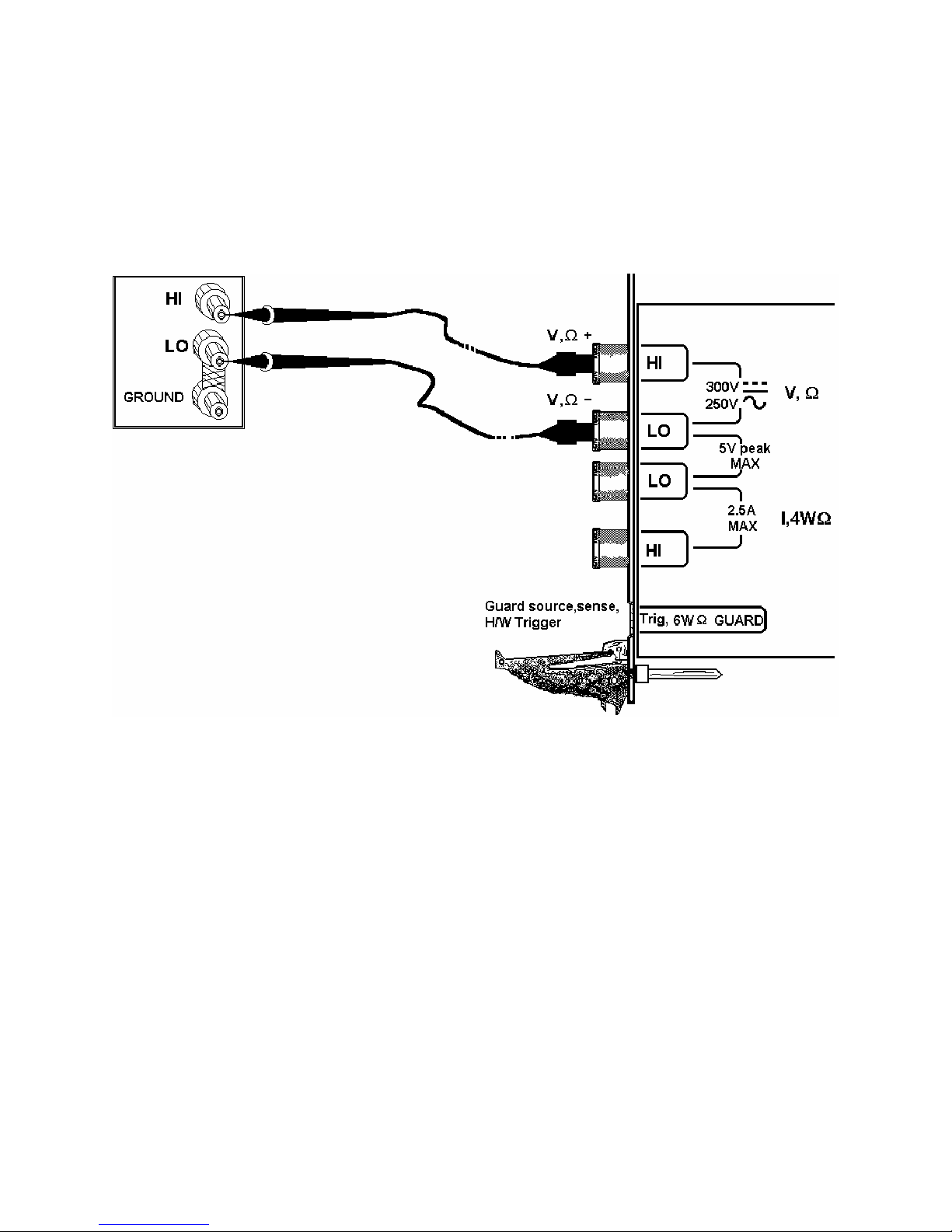
4.1.2 True RMS AC Voltage Measurements
ACV is specified for signals greater than 1mV, from 10 Hz to 100 kHz. The ACV function is AC coupled, and
measures the true RMS value of the waveform. As with virtually all true-RMS measuring meters, the SMX2040
may not read a perfect zero with a shorted input. This is normal.
ACV measurements, if possible, should have the NEUTRAL or GROUND attached to the SMX2040 V,Ω -
terminal. See Figure 4-1, below. This prevents any “Common Mode” problems from occurring (Common Mode
refers to floating the SMX2040 V,Ω LO above Earth Ground.) Common Mode problems can result in noisy
readings, or even cause the computer to hang-up under high V x Hz input conditions. In many systems, grounding
the source to be measured at Earth Ground (being certain to avoid any ground loops) can give better results.
Figure 4-1. Make Voltage measurements with the source ground attached to the SMX2040 V,Ω - to
minimize “Common Mode” measurement problems.
4.1.3 AC Peak-to-Peak and Crest Factor Measurement (SMX2044)
Measurement of Peak-to-Peak, Crest Factor and AC Median values requires a repetitive waveform between 30 Hz
and 100 kHz. The DMM must be in AC voltage measurement mode, with the appropriate range selected. Knowing
the Peak-to-Peak value of the waveform is useful for setting the Threshold DA C (d escrib ed below). This latter
function is a composite function, and may take over 10 seconds to perform.
Artisan Technology Group - Quality Instrumentation ... Guaranteed | (888) 88-SOURCE | www.artisantg.com
25 Signametrics
Page 27
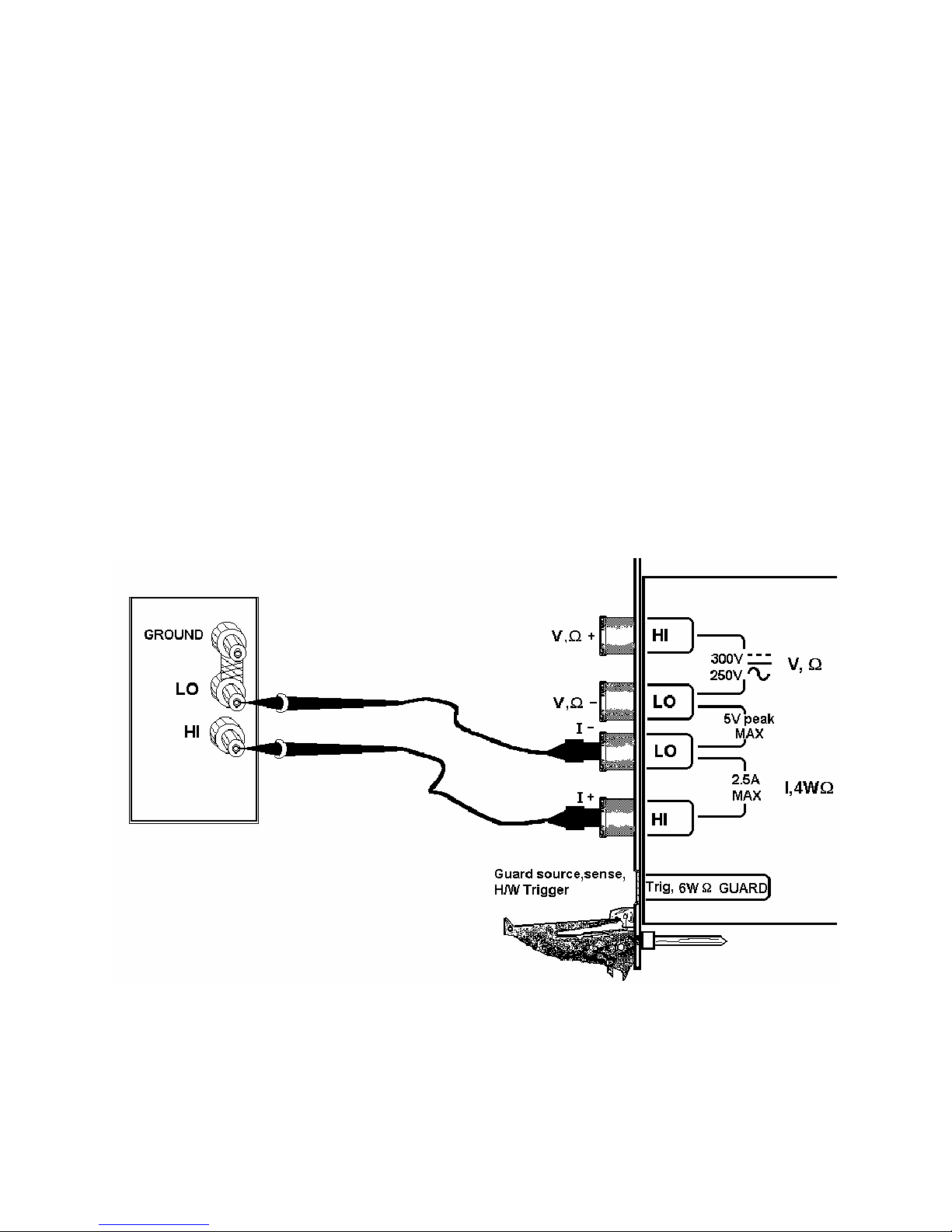
4.1.4 AC Median Value Measurement (SMX2044)
To better understand the usage of this function, you should note that the DMM makes all AC voltage measurements
through an internal DC blocking capacitor. The voltage is thus “AC coupled” to the DMM. The measurement of the
Median value of the AC voltage is a DC measurement performed on the AC coupled input signal. This measurement
returns the mid-point between the positive and negative peak o f the waveform. The Median value is used for setting
the comparator threshold level for best counter sensitivity and noise immunity. (It is difficult to measure the
frequency of a low duty cycle, low amplitude AC signal since there is DC shift at the comparator input due to the
internal AC coupling. The SMX2044 overcome this problem by allowing you to set the comparator threshold level).
For further information on the usage of AC Median value and Peak-to-Peak measurements, and the Threshold DAC,
see the “Frequency and Timing Measurements” section below.
This function requires a repetitive signal. The DMM must be in AC voltage measurement mode, with the
appropriate range selected.
4.2 Current Measurements
The SMX2040, 42, 44 measure from 10 ηA to 2.5 A. Use the I, 4WΩ terminals, being certain to always leave the
V,Ω + & - terminals disconnected. Use the AC/DC button to switch between AC and DC.
The Current functions are protected with a 2.5 A, 250 V fuse.
Warning! Applying voltages > 35 V to the I+, I- inputs can cause personal injury and/or damage to your
DMM and computer! Think before applying any inputs to these terminals!
When making sensitive DC current measurements, be sure to use the Relative function to zero out any residual
errors of the SMX2040. This is easily accomplished by opening all inputs to the SMX2040 and performing Relative
in the appropriate DCI range.
Figure 4-2. AC and DC Current measurement connection.
4.2.1 Improving Current Measurements
W
hen making sensitive DC current measurements, be sure to use the Relative function to zero out any residual
erro M and performing
rs of the SMX2040. This is easily accomplished by disconnecting all terminals to the DM
Relative in the appropriate DCI range. Using the S-Cal (DMMCalibrate()) prior to activating Relative will
improve accuracy further. Although the SMX2040 family is designed to withstand up-to 2.5A indefinitely, be awa
that excessive heat may be generated when measuring higher AC or DC currents. If allowed to rise this heat may
adversely effect subsequent measurements. In consideration with this effect, it is reco
Signametrics 26
Artisan Technology Group - Quality Instrumentation ... Guaranteed | (888) 88-SOURCE | www.artisantg.com
re
mmended that whenever
Page 28

ractical, higher current measurements be limited to short time. The lower two ranges of DC current may be
p
effected by relay contamination. If the measurements
between 20mA and 50mA DC to the current terminals and clean the K2 relay using the DMMCleanRelay(0, 2,
200). Repeat this until the measurements are stable.
seem unstable or high, while in IDC measurement, apply
4.2.2 Low Level DC Curr
or low level current measurements use the
F
SMX urement function is facilitated by the DMM’s low
2040 can measure very low currents. This hidden meas
leakage front-end and a virtual 1
this VDC range, it is practical to measure down to 20pA. The maximum current
easured has more to do with the user’s acceptable burden voltage (the voltage drop across the
m
0.0MΩ input resistance. With a typical offset error of less than 100µV in
ent Measurements
V, Ω+ and V, Ω- terminals. Using the 33V DCV range, the
value that can be
1
0.0MΩ
shunt) then the DMM limitations. Assuming a maximum burden voltage of 3.3V the maximum current
level is 330ηA. This range is well within leakage measurements required in most semiconductor testing.
It is also a very quite and stable. Since the DMM does not have an explicit low current function, it i
1
0.0M
necessary to calculate the current, which is equal to the measured voltage divided by
Ω.
s
4.2.3 Extended DC Current Measurements (SM2044)
The leakage measurement function can also be used to measure low-level currents. Using a relatively high value
shunt resistor and setting the leakage test voltage to 0V allows measurements of super low level currents, without
any burden voltage. Read the leakage current section of the manual for more details.
4.3 Resistance Measurements
esistance is measured with one of eight (six in the SMX2040) precision current sources, with the DMM displaying
R
the resistance value. Most measurements can be made in the 2-wire mode. 4-wire ohms is used to make precision
low resistance measurements. All resistan
errors. See section section 4.3.5 for details.
ce measurement modes are susceptible to Thermo-Voltaic (Thermal EMF)
4.3.1 2-wire Ohm Measurements
The DMM measure using 330Ω to 33 MΩ ranges. The SMX2042 and SMX2044 add 33 Ω and 330 MΩ ranges.
Use the V,Ω+, V,Ω- terminals, being certain to always disconnect the I+, I- terminals.
Most resistance measurements can be made using the simple 2-wire
e
nd of the resistor, and the V,Ω- to the other end. If the resistor to be measured is less than 30 kΩ, you should null
out any lead resistance errors by first touching the V,Ω+ and V,Ω- test leads together and then performing a
Relative function. If making measurements above 300 kΩ, you should use shielded or twisted leads to minimize
noise pickup. This is especially true for measurements above 1 MΩ.
You may also want to control the Ohms current used in making resistance measurements. (See the Specifications
section, "Resistance, 2-wire and 4-wire", for a table of resistance range vs. current level.) All of the Ohms ranges of
the SMX2040 have enough current and voltage compliance to turn on diode junctions. For characterizing
semiconductor part types, use the Diode measurement function. To avoid turning on a semiconductor junction, you
may need to select a higher range (lower current). When checking semiconductor junctions, the DMM displays a
resistance value linearly related to the voltage across the junction .
For applications requiring resistance measurements higher than 330 MΩ, the Extended Resistance Measurement
method is available with the SMX2044.
Ohms method. Simply connect V,Ω+ to one
4.3.2 4-wire Ohm Measurements
4-wire Ohms measurements are advantageous for making measurements below 330 kΩ, eliminating lead resistance
errors. The Voltage (V,Ω) Input terminals serve as the current “Source” (i.e. they provide the current stimulus in the
ohms measurement), and the I, 4WΩ Input terminals are the “Sense” inputs. The Source + and Sense + leads are
connected to one side of the resistor, and the Source - and Sense - leads are connected to the other side. Both Sense
leads should be closest to the body of the resistor. See Figure 4-3.
4-wire Ohm makes very repeatable low ohms measurements, from 100 µΩ (10 µΩ for SMX2042, 44) to 330 kΩ. It
is not not recommended to us 4WΩ when making measurements above 100 kΩ, although 4-wire ohms is allowed
27 Signametrics
Artisan Technology Group - Quality Instrumentation ... Guaranteed | (888) 88-SOURCE | www.artisantg.com
Page 29
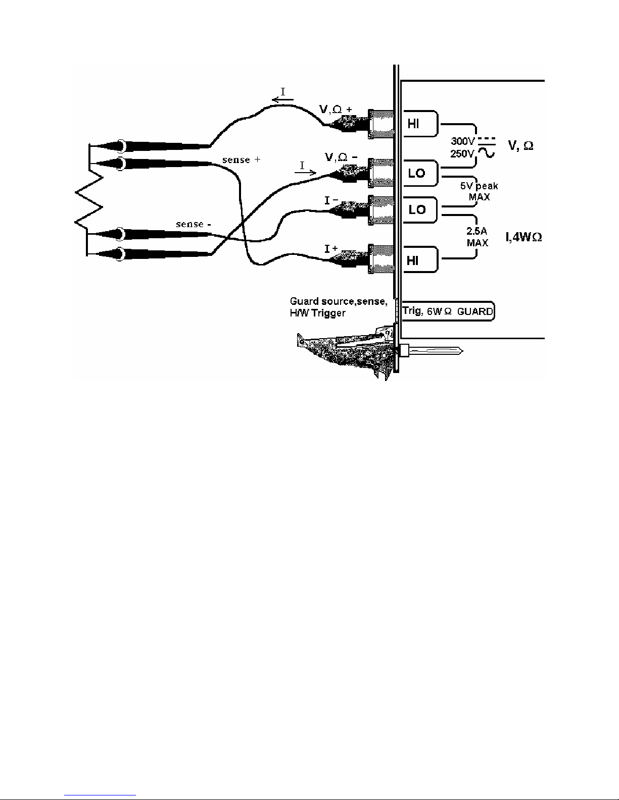
up to 330 kΩ. 4-wire measurements are disabled above 330 kΩ since the extra set of leads can actually degrade the
accuracy, due to additional leakage and noise paths.
Figure 4-3. The I- and I+ sense leads should be closest to the body of the resistor when making 4WΩ
mea
surements.
4.3.3 Using Offset Ohms function
Inadvertent parasitic leakage currents, Thermo voltaic voltages and other voltages in series can effect resistance
measurements with the measured resistance. This is common particularly when doing in-circuit measurements, and
it could manifest as having a significantly different readings when changing Ohms ranges. In addition to eliminating
such error, this function can also be used to measure internal resistance of low value voltage sources such as variou
batteries and supplies. Use the normal 2-Wire or 4-Awire Ohms connection, and set the Offset Ohms to the enabled
or disabled state using the DMMSetOffsetOhms() function. When set TRUE, the measurement rate will be about
th
of the set DMM rate. Both negative and positive polarity voltages can be handled as long as the total voltage
1/10
including the Ohms source current times the measured resistance plus the parasitic voltage are less than 3.7V. To
calculate this voltage consult the specification part of this manual for the specific current for each Ohms range. Th
default value of this function is FAL
ue to it’s different hardware, the SMX2042 is different in that one of the DMM relays is being used to perform
D
this
operation, which can be heard.
SE. This function is implemented for the SMX2040, SMX2042 and SMX2044.
e
4.3.4 6-wire Guarded Resistance Measurement (SMX2044)
The SMX2044 provides a guarded 6-wire resistance measurement method. It is used to make resistance
measurements when the resistor-under-test has other shunting paths that can cause inaccurate readings. This method
isolates the resistor-under-test by maintaining a guard voltage at a user-defined node. The gu
e shunting of the DMM Ohms source current from the resistor-under-test to other components. The Guard Source
th
and Guard Sense terminals are provided at pins 1 and 6 of the DIN connector respectively.
Warning! The DIN connector pins are only protected to a maximum of 35 V with
ny other DMM terminal. Do not apply any voltages greater than 35 V to the DIN connector pins. Violating
a
this limit may result in personal injury and/or permanent damage to the DMM.
Example: Assume a 30 kΩ resistor is in parallel with two resistors, a 510 Ω and a 220 Ω, connected in series. In
normal resistance measurement, the 510 Ω and 220 Ω would shunt most of the DMM Ohms source current, causing
Signametrics 28
ard voltage prevents
respect to the chassis or
a
s
Artisan Technology Group - Quality Instrumentation ... Guaranteed | (888) 88-SOURCE | www.artisantg.com
Page 30
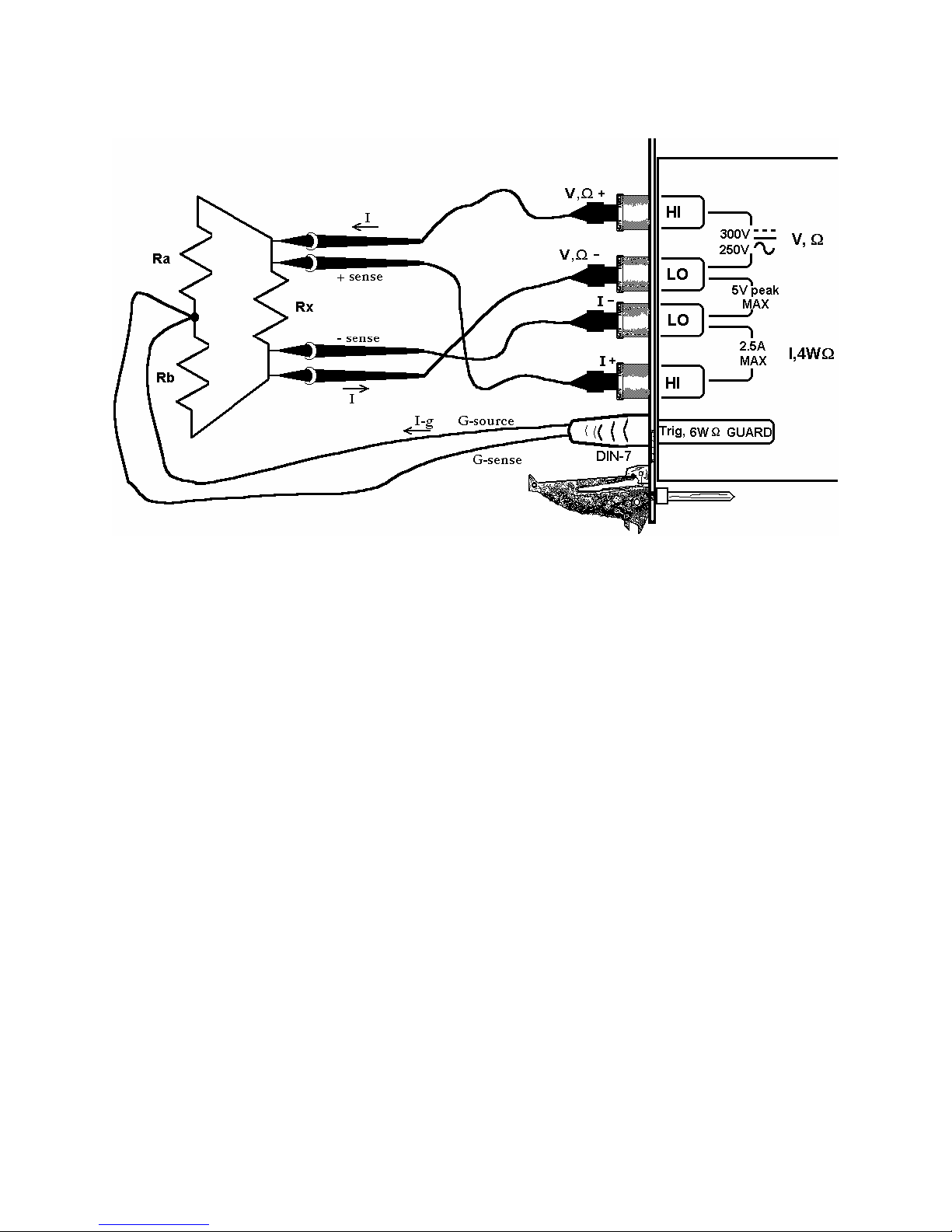
an inaccurate reading. By sensing the voltage at the top of the 30 kΩ, and then applying this same voltage to the
junction of the 510 Ω and 220 Ω, there is no current
MX2044 accurately measures the 30 kΩ resistor.
S
flow through the shunting path. With this “guarding”, the
Figure 4-4. 6-wire guarded in-circuit ohms measurement configuration.
The current compliance of the Guard Force is limited to a maximum of 20 mA and is short-circuit protected. The
resistor connected between the low of the 4-wire terminals and the guard point is the burden resistor, or R
: R
the limited guard source current, this resistor can not be lower than R
ohms source current for the selected range, and R
Ω range and measuring a 300 Ω resistor imposes a limit on R
resistor, R
, does not have this limit imposed on it, selecting the measurement polarity, Ra can become R
a
is the resistance being measured. For exa
x
b
bmin
of at least 15 Ω or greater. Since the top burden
versa. For cases where this limit is a problem, simply set the measurement polarity such that R
= Io * Rx / 0.02, where Io is the
bmin
mple, selecting the 330
is the higher of the
a
. Due to
b
and vise
b
two burden resistors.
To measure values greater than 330 kΩ using the 6-wire guarded method, it is necessary to select the 2-wire ohms
function, and maintain the 6-wire connection as in Figure 4-4 above.
4.3.5 Leakage Measurements (SMX2044)
The SMX2044 measures leakage currents by applying a DC voltage across the load and measuring the current
through it. An external shunt resistor, R
voltage at which leakage is measured is set using DMMSetDCVSource(), and the value of R
DMMSetExternalShunt() (the default is 1 MΩ). Leakage current is read using DMMRead(), DMMReadStr() or
DMMReadNorm() functions. Depending on the value of R
between –10V and +10 V. Specifically; the maximum voltage is limited to 10.2V – (R
) measurement range and accuracy depends on the shunt resistor being used. The range is set as 3.3V/RS, with
(I
L
resolution of 10uV/R
. For instance, with RS equal to 1MΩ, the maximum leakage current is 3.3uA with resolution
S
of 10pA, and at full scale the maximum test voltage is 6.7V. The test voltage is adjusted whenever a measurement is
made. Therefore, if the leakage current being measured varies significantly over time, it is best to repeatedly read
the DMM allowing the DMM to make corrections to the internal source voltage, compensating for drop across the
shunt. Performing open terminal calibration will imrove the accuracy of this function (use
DMMOpenTerminalCal()
with all terminals open). Refer to Figures 4-5. See section 2.6 for specifics. Setting
the source to closed loop mode, DMMSetSourceMode(), will improve the accuracy of the test voltage.
is used to sense the current. See Figures 4-5 for connection. The DC
S
is entered using
S
and the leakage current, the test voltage may be set
S
* IL). The leakage current
S
Artisan Technology Group - Quality Instrumentation ... Guaranteed | (888) 88-SOURCE | www.artisantg.com
29 Signametrics
Page 31

Figure 4-5. Leakage Test Configuration. Measurement of reverse diode leakage at 3.3V.
4.3.6 Extended Resistance Measurements (SMX2044)
The Extended Resistance measurement funct
here the last forces a predefined current, this function forces sp
W
easurement is limited to pre defined current sources, this function has a variable voltage, and it limits current flow
m
by an external sense resistor. To perform this measurement use the connection diagram in Figure 4-6. Enter the
value of the sense resistor R
using DM
S
MMSetDCVSource(). Due to the avD
is he other hand, the ability to set to some low
th function is fit for very high value resistance measurements. On t
ages is significant in applications where specific test voltage is revolt quired such as to prevent semiconductor’s
turn-on, or prevent sensitive sensors’ damage due to access voltage or current. The DMM compensates for the
voltage drop across the sense resistor as to provide the specified test voltage. Each time the DMM makes a
measurement using DMMRead(), DMMReadStr() or the DMMReadNorm, it adjusts the test voltage. There are
several limitations that should be considered while using this function. The internal voltage source of the SM2044 i
limited to about +/-10.2V. Therefore the sum of the voltages across the sense resistor and the measured resistor is
limited to this amount. Also the maximum voltage allowed across the sense resistor is limited to 3.3V. Exceeding
either value will result in Over Range reading. The limit imposed by the shunt resistor may be expressed as V
< 3.3V, where VL is the test voltage, RX is the resistance being measured, and RS is the external sense resistor
R
S
value. The source voltage limit may be expressed as V
set the value of the external shunt being used. Use the DMMSetDCVSource() to set the test voltage (the voltage
across the resistor being measured). For high value resistances, the shunt should be of high value and vise ve
This function is useful for testing high value resistive elements such as cables, transform
such as printed circuit boards, connectors and semiconductors.
As an examp er unt ol e, the lowest resistor one can measure will
be 1.2122MΩ un V
V
. The s ce volta imit is rea hen VL is .5V and th
S
si (1 Ω/5 ) = 10.2
nce 8.5V + 1.0M .001MΩ V.
le, consid a 1.0MΩ sh and a 4V test v tage. In this cas
. The sh t voltage
is at ere sin * 4V / = 3.3V which is the limit for
S
our ge l ched w set to 8 e measured resistance falls below 5.001MΩ
ion operates as complement of the standard resistance measurement.
ecified voltage. Where the normal resistance
MSetExternalShunt(), and set the test voltage with
ailability of a much higher test voltage than the normal resistance function,
L/RX
(1+RS/RL) < 10.2V. Use the DMMSetExternalShunt() to
L
rsa.
ers, and other leaky objects
its limit h ce 1.0MΩ 1.2122MΩ
*
s
Signametrics 30
Artisan Technology Group - Quality Instrumentation ... Guaranteed | (888) 88-SOURCE | www.artisantg.com
Page 32

Figure 4-6. Extended Ohms range.
4.3.7 Effects of Thermo-Voltaic Offset
Resistance measurements are sensitive to Thermo-Voltaic (Thermal EMF) errors, which can be caused by poor test
leads, relay contacts and other elements in the measurement path. These errors effect all measurement methods,
including 2-Wire, 4-Wire, 6-Wire and 3-Wire (guarded 2-Wire ohms). To quantify this error, consider a system in
which signals are routed to the DMM via a relay multiplexing system. Many vendors of switching products do not
provide Thermal EMF specification. It is common to find relays that have more than 50 µV EMF. With several
relay contacts in the path, the error is very significant. It is possible to measure it using the SMX2040 330mV DC
range. To do this, close a single relay that is not connected to any load, wait for a short time (about 2 minutes), than
measure the voltage across the shorted relay contacts. Make sure to short the DMM leads and set ‘relative’ to clear
the DMM offset prior to the measurement. To calculate worst case error, count all relay contacts which are in series
with the measurement (V,Ω+, V,Ω- terminals in 2-Wire, and I+, I- terminals in 4-Wire mode). To calculate the
worst case error, multiply this count by the Thermal EMF voltage. Use Ohms law to convert this voltage to
resistance error as in the following table.
Resistance Measurement Errors due to Thermo-Voltaic offsets.
SM2042
Range
33 Ω
330 Ω
3.3 kΩ
33 kΩ
330 kΩ
3.3 MΩ
33 MΩ
330 MΩ
Ohms
Current
10 mA
1 mA
1 mA
100 uA
10 uA
1 uA
100 nA
10 nA
DMM
Resolution
10 µΩ 1 mΩ 10 mΩ 100 mΩ
100 µΩ 10 mΩ 100 mΩ 1 Ω
1 mΩ 10 mΩ 100 mΩ 1 Ω
10 mΩ 100 mΩ 1 Ω 10 Ω
100 mΩ 1 Ω 10 Ω 100 Ω
1 Ω 10 Ω 100 Ω 10 Ω
100 Ω 100 Ω 1 kΩ 100 Ω
10 kΩ 1 kΩ 10 kΩ 100 kΩ
Error due to
10 µV EMF
Error due to
100 µV EMF
Error due to 1
mV EMF
Artisan Technology Group - Quality Instrumentation ... Guaranteed | (888) 88-SOURCE | www.artisantg.com
31 Signametrics
Page 33

4.3.8 Guarding High Value Resistance Measurements (SMX2044)
Measuring high value resistors using the 2-Wire function require special attention. Due to the high impedances
involved during such measurements, noise pickup and leakage could be very significant. To improve this type of
measurement it is important to use good quality shielded cables with a low leakage dielectric. Even with a good
dielectric, if a significant length is involved, an error would result due to leakage. Figure 4.7 exemplifies this error
source. It is important to emphasize that in addition to the finite leakage associated with the distributed resistance,
, there must also be a voltage present between the two conductors, the shield and the center lead, for leakage
R
L
current to develop. Provided there was a way to eliminate this voltage, leakage would have been eliminated.
Figure 4-7. Error due to cable leakage.
The SM2044 provides an active guard signal that can be connected to the shield and prevent the leakage caused by
the dielectric’s finite resistance. With the shield voltage guarded with Vx, as indicated in Figure 4-8, there is 0V
between the shield and the high sense wire, and therefore no current flows through R
.
L
Figure 4-8. Guarding eliminates errors due to leakage associated with high resistance measurements.
4.4 RTD Temperature Measurement (SMX2044)
For temperature measurements, the SMX2044 measure and linearize RTDs. 4-wire RTD’s can be used by
selecting the appropriate RTD type. Any ice temperature resistance between 25 Ω and 10 kΩ can be set
for the platinum type RTDs. Copper RTDs can have ice temperature resistance values of 5 Ω to 200 Ω.
The highest accuracy is obtained from 4-wire devices, because the resistance of the test leads is nulled
out. The connection configuration for RTDs is identical to 4-wire Ohms.
4.5 Internal Temperature (SMX2044)
Signametrics 32
Artisan Technology Group - Quality Instrumentation ... Guaranteed | (888) 88-SOURCE | www.artisantg.com
Page 34

A special on board temperature sensor allows monitoring of the DMM’s internal temperature. This provides the
means to determine when to run the self-calibration function (S-Cal) for the DMM, as well as p r edicting the
performance of the DMM under different operating conditions. W hen used properly, this measurement can enha
the accuracy and stability of the DMM. It also allows monitoring of the chassis internal temperature, which is
important for checking other instruments.
nce
4.6 Diode Characterization
The Diode measurement function i
display a semiconductor device’s forward or reverse voltage. The DMM measures diode voltage at a selected
current. The available source currents for diode I/V characterization include five DC current values; 100 ηA, 1 µA,
10 µA, 100 µA and 1 mA. The SMX2044 have an additional 10 mA range. The SMX2044 also has a variable
current source which can be used concurrently with DCV measurement (see “Source Current / Measure Voltage”).
This allows a variable current from 10 ηA to 12.5 mA. The maximum diode voltage compliance is approximately 4
V.
Applications include I/V characteristics of Diodes, LEDs, Low voltage Zener diodes, Band Gap devices, as well as
IC testing and polarity checking. Typical current level uncertainty for diode measurements is 1%, and typical
voltage uncertainty is 0.02%.
s used for characterizing semiconductor part types. This function is designed to
4.7 Capacitance Measurement (SMX2044)
The SMX2044 measure capacitance using a differential charge slew method, where variable currents are utilized to
produce a dv/dt across the capacitor. Use short high quality shielded probe cables with no more than 500 pF. With
the exception of the 10 ηF range, each of the ranges has a reading span from 5% of range to full scale. Capacitance
values less than 5% of the selected range indicate zero. Since some large value electrolytic capacitors have
significant inductance, as well as leakage and series resistance, the Autoranging function may not be practical.
Because Capacitance measurement is sensitive to noise, you should keep the measurement leads away from noise
sources such as computer monitors. For best measurement accuracy at low capacitance values, zero the DMM using
the ‘Relative’ while in the 10 ηF range. The effect of the cable qu ality and its total capacitance is significant
particularly on low value caps. For testing surface mount parts, use the optional Signametrics SMT Tweezer probes.
See Figure 4-9 for connection.
Figure 4-9. Measuring capacitors or inductors is best handled with shielded probe wires.
Artisan Technology Group - Quality Instrumentation ... Guaranteed | (888) 88-SOURCE | www.artisantg.com
33 Signametrics
Page 35

4.8 In-Circuit Capacitance Measurement (SMX2044)
A second method provided for measuring capacitors i
nction, the advantage of this method is that the default stimulus is set at 0.4 5V peak, which is lower than a
fu
semiconductor junction on voltage. It may also be set over a wide ra
ability of this function to measure capacitors that have a very low v a
do using conventional methods. This test function operates by figuring the complex impedance and extracting from
it both, the capacitance and resistance. The measurement is practical down to a few hundred Pico Farads, and up to
several thousands micro Farads, with parallel resistances as low as 20Ω to 300Ω depending on range. Once set to
this function, use DMMRead(), DMMReadStr() and DMMReadNorm() to measure the capacitance value. To ge
the resistance value use DMMGetACCapsResist() following a read. Each of the ranges must be calibrated with
open terminals prior to making measurements. Each range must be calibrated. Do this by activating the AC-Caps
unction, selecting the ran
f
the AC source signal. This open Calibration operation must be performed with the measurement cable or probes
plugged into the DMM, with the other end open. See figure 4-9 above for connection. If not modified by the
DMMSetACCapsLevel() function, when making a measurement the DMM uses a default voltage of 0.45Vpk,
hich means that a sine wave that has a peak-to-peak amplitude of 0.9V. This level is used during both,
w
alibration and measurements. Since the DMM is optimized for this value, and it is well below most semiconductors
c
On voltage, it is recommended not to change the level from this default value. The stimulus vo
0.1V peak to 5V peak using the DMMSetACCapsLevel() function. Any time the stimulus level is adjusted; open
calibration must be carried out. The results of DMMOpenCalACCaps() are kept in memory until the DLL is
unloaded. Repeating Open calibration periodically will result in improved accuracy. AC Capacitance measurement
function must be used with a DMM reading rate of 10rps. Other functions of interest for this operations are
MMSetACCapsDelay() and SetACCapsFre
D
ge to be calibrated and issuing DMMOpenCalACCaps(). The last function normalizes
s the AC based method. Though not as accurate as the above
nge of voltages. A further advantage is the
lue parallel resistance, which is impossible to
open
ltage can be set from
q().
t
4.9 Inductance Measure
he urce with a frequency range of 20 Hz to 75 kHz. Since
T SMX2044 measures inductance using a precision AC so
indu e the appropriate generator frequency. In addition to
ctors can vary greatly with frequency, you should choos
inductance, the inductor’s Q factor can be measured. A shielded, high quality cable is highly recommended. F
best accuracy, perform the Open Terminal Calibration function within an hour of inductance measurements. The
Open Terminal Calibration function must be performed with the cables plugged into the DMM, but with the other
end open circuited. This process characterizes the internal signal path inside the DMM, the open application cable
and the DMM circuitry.
For best measurement accuracy at low inductance values, zero the DMM often by using the ‘Relative’ function with
the leads shorted. This must be done following Open Terminal Calibration operation. This Relative action measures
and removes the inductance of the DMM signal path including that of the application cable being used.
ment (SMX2044)
or
,
.10 Characteristic Impedance Measurement (SMX2044)
4
To measure a transmission line’s characteristic impedance, measure the cable’s capacitance C (with the end of the
cable open) and then it’s inductance L (with the end of the cable shorted). The cable’s impedance equals the square
root of L/C. Be certain the cable is long enough such that both the capacitance and ind
ecified measurement range of the SMX2044.
sp
uctance are within the
4.11 Trigger Operation
4.11.1 External Hardware Trigger
he Trigger functions provide for a stand-alone capture of measurements. The local controller supervises the
T
oper s it back to the PXI bus. The reading
ation, and when conditions are valid, it captures data into its buffer, or send
rate must be set to 10 rps or higher. The External Trigger’s isolated high and low input lines are provided at pins 7
(+) and 4 (-), respectively, on the DIN connector located on the front panel of the instrument. You may abort the
External Trigger’s wait state using the Disarm command. It is important to note that the External Hardware Trigge
is Wire-Ored with the PXI triggers. Therefore, while using the External Trigger, the PXI trigger input line selected
see section 4.11.4) must
(
th
e External Hardware trigger must at a low logic level, or disconnected. Failing to do this will result in a disabeled
trigger. The PXI and External Hardware trigger software functions includes: DMMArmTrigger, which responds to
be at a low logic level (inactive). While using the PXI trigger inputs as the trigger source,
r
Signametrics 34
Artisan Technology Group - Quality Instrumentation ... Guaranteed | (888) 88-SOURCE | www.artisantg.com
Page 36

posi lectable edge parameter. Read about
tive edge, DMMSetBuffTrigRead, and DMMSetTrigRead have a se
these functions in the Windows Command Language section (5.6) for details.
Warning! The DIN connector pins are only protected to a maximum of 30 V with respect to the chassis or
any other DMM terminal. Do not apply any voltages greater than 30 V to the DIN connector pins. Violatin
this limit may result in personal injury and/or permanent damage to the DMM.
4.11.2 Analog Threshold Trigger
This mode trigg
MM Analog trigger. The DMM’s local controller waits for the level crossing and captures up to 64 readings,
D
which are saved on board; at the current DMM measurement function, range and rate. The reading rate must be set
to 10 rps or higher. You can abort this mode by sending the DMM a Disarm command to the Analog Trigger.
ers the DMM at a specific input level. A command to the DMM sets a threshold value and arms the
4.11.3 Software Issued Triggered Operations
There are several software trigger functions. They cause the DMM to make a single or multiple measurements, w
or without setteling readings. These include DMMSetBuffTrigRead, DMMSetTrigRead, DMMTrigger,
DMMBurstRead, and DMMBurstBuffRead. Read about these functions in the Windows Command Language
section (5.6) for details.
ith
4.11.4 Using the PXI bus Trigger Facilities
The SMX2040 series of Digital Multimeters are designed to interface to the PXI J2 Triggers. That includes the
PXI_TRIG0 through PXI_TRIG6 and PXI_STAR trigger. The trigger to the DMM is a Wire-Ored function of the
external trigger from the DIN-7 connector, and the PXI_TRIGn input. The data ready signal from the SMX2040
series can be selected to drive PXI_TRIG1 through PXI_TRIG6 or PXI_STAR trigger. Read section 4.10.1 to
prevent Trigger input conflicts.
g
Figure 4-10. PXI Trigger input/output selection switch is located near PXI J2 connector towards the back
of the DMM.
4.11.4.1 PXI Trigger Outputs
The DMM issues a Data Ready pulse each time the A/D is done making a measurement, indicating data
is ready to be read. A short (about 140µs) negative pulse is issued for each measurement, with the
positive edge indicating data is ready. The Trigger output is selected using S4, S5, and S6 DIP switch
located near the PXI connector. The trigger pulse can be set to be output to any of the following lines.
Artisan Technology Group - Quality Instrumentation ... Guaranteed | (888) 88-SOURCE | www.artisantg.com
35 Signametrics
Page 37

Switch Settings
S6 S5 S4
0 0 0 Disables trigger output
0 0 1 PXI_TRIG1
0 1 0 PXI_TRIG2
0 1 1 PXI_TRIG3
1 0 0 PXI_TRIG4
1 0 1 PXI_TRIG5
1 1 0 PXI_TRIG6
1 1 1 PXI_STAR
Trigger Output Routing
4.11.4.2 PXI Trigger Inputs
The trigger input to the DMM is the wired-ored signal of the trigger input from the DIN-7 connector and
the PXI bus trigger. Make sure that no signal is connected to the DIN-7 trigger input while the PXI trigger
is in use. When using the DIN-7 trigger input make sure the the trigger input select switches are set to
Disabled position, or the selected PXI Trigger input is at a logic low level. Read about the operation of the
External Hardware trigger in the above sections, since that operation pertains to both, the external and
the PXI trigger input operations. The Trigger input is selected using S1, S2, and S3 DIP switch located
near the J2 connector of the DMM. The DMM trigger input may be selected from any of the following
lines.
Switch Settings
S3 S2 S1
0 0 0 Disables trigger input *
0 0 1 PXI_TRIG1
0 1 0 PXI_TRIG2
0 1 1 PXI_TRIG3
1 0 0 PXI_TRIG4
1 0 1 PXI_TRIG5
1 1 0 PXI_TRIG6
1 1 1 PXI_STAR
* - Rev-B hardware and above.
Trigger input Routing
4.12 Frequency and Timing Measurements (SMX2042, 44)
While the maximum RMS reading is limited to the set range, you can use most of the timing functions even if the
RMS voltage reading indicates Overrange. This is true as long as the input peak-to-peak value does not exceed 5.75
times the selected range ( 5.75 x 330 mV = 1.9 V p-p with the 330 mV range).
4.12.1 Threshold DAC
All timing measurements utilize the AC Voltage path, which is AC coupled. You need to select the appropriate
ACV range prior to using the various frequency and timing measurement functions. The SMX2044 have a novel
feature to accurately make these measurements for all waveforms. Unlike symmetrical waveforms such as a sine
wave and square wave, non-symmetrical waves may produce a non-zero DC average at the frequency counter’s
comparator input. Other DMMs have the comparator hard-wired to the zero crossing. The SMX2044 include a
bipolar, variable Threshold DAC for improved performance of these measurements. The Threshold DAC allows the
internal timing comparator to trigger at a specific DC level. Functions affected by the Threshold DAC include
frequency, period, pulse-width, duty-cycle, and the totalizer.
The Threshold DAC has 12 bits of resolution. Depending on the selected ACV range, this bipolar DAC can be set
from a few mV to effectively several hundred volts (referred to the input of the DMM), positive or negative. See the
Specifications sections for the limits of AC Median Value measurements and Threshold DAC settin gs.
The best setting of the Threshold DAC is based on the AC Median Value and Peak-to-Peak measurement described
earlier. For example, a 5 V logic signal with 10% duty cycle will result in median value of 2 V, whereas a 90% duty
cycle signal will have a –2 V median value. Setting the Threshold DAC to the appropriate median value will result
in reliable and accurate timing measurements in each case.
Signametrics 36
Artisan Technology Group - Quality Instrumentation ... Guaranteed | (888) 88-SOURCE | www.artisantg.com
Page 38

Figure 4-11. AC coupled timing measurements with Threshold DAC.
With the 3.3 ACV range selected, a 10% duty-cycle square wave with 5 V peak-to-peak value, presents a
peak-to-peak signal at the internal measuring circuits of –0.5 V to + 4.5 V. The AC Median Value is
+2.0 V. By setting the Threshold DAC to the Median value, the internal measuring circuits are properly
biased for best performance.
Figure 4-12. Comparator and Threshold DAC Settings
4.12.2 Frequency and Period Measurements
Both Freq. and Per check boxes are only visible when ACV or ACI functions are selected. These check boxes are
used to make frequency or period measurements. Freq. measures from 1 Hz to 300 kHz. When activated, the
ontrol panel alternately updates the amplitude reading followed by the frequency reading. The reading rate is
c
slow y is activated. In the Windows control panel, period (Per) is also selectable.
er than indicated when frequenc
Once the frequency range is acquired, Frequency and Period have a maximum measurement time of about 1 second.
It could take up to five measurements before the correct frequency range is auto-selected. This process is automatic.
Once within range, the next frequency measurement is made at the last selected range.
Both Frequency and Period measurement performance can be improved by properly setting the Threshold DAC,
novel feature of the SMX2044. See “Threshold DAC”, “AC Median Value”, and “Peak-to-Peak” measurements for
further details.
Artisan Technology Group - Quality Instrumentation ... Guaranteed | (888) 88-SOURCE | www.artisantg.com
a
37 Signametrics
Page 39

4.12.3 Duty Cycle Measurement
Duty Cycle of signals from 1 Hz to 100 kHz can be measured. The minimum positive or negative pulse width of
the signal must be at least greater than 2 µs. When measuring duty cycle precisely, the voltage at which the
measurement is made is important, due to finite slew rates of the signal. The Threshold voltage can be set for
precise control of the level at which duty cycle is measured. For best measurement results, set the Threshold DA
the Median value. T
selected scale.
his is particularly important for signals with low duty-cycle and small amplitude relative to the
C to
4.12.4 Pulse Width
User selectable positive or negative pulse widths may be measured for signal frequencies of 1 Hz to 100 kHz and
minimum pulse widths of 2 µs. The Thre d DAC feature allows measurements at a pre-defined signal level. See
Threshold DAC above for more det
To measure pulse width, the DMM must be in the AC volts range appropriate for the input voltage. Keeping the
peak-to-peak amplitude of the measured signal below 5.75 times the
li on of the AC circuitry and gives the best performance.
near regi
shol
ails.
set range will guarantee the signal is within the
a
4.12.5 Totalizer Event Counter
he totalizer can be selected while the DMM is in the ACV mode. It is capable of counting events such as over-
T
voltage excursions, switch closures, decaying resonance count, etc. The active edge polarity can be set for a positive
or negative transition. A count of up to 10
events per second.
The Threshold DAC can be set for a negative or positive voltage value. See Threshold DAC above for more details.
9
can be accumulated. The maximum rate of accumulation is 30,000
Example One: To monitor and capture the AC line for positive spikes which exceed 10% of the nominal 120 V
RMS value, first select ACV 250 V range, than set the Threshold DAC to 186.7 V. This value is the peak value of
120 V RMS plus 10% (120V + 10%) X
times this value was exceeded.
Example Two: Defects in coils, inductors, or transformers can be manifested as an increased decay, or greatly
attenuated resonance when stimulated with a charged capacitor. The Totalizer function can be utilized to count
transitions above a preset Threshold voltage as in the figure below.
). Enable the Totalizer and read it periodically to get the number of
2
Figure 4-13. Measuring inductor Q by counting transitions of decaying resonance with preset threshold.
Signametrics 38
Artisan Technology Group - Quality Instrumentation ... Guaranteed | (888) 88-SOURCE | www.artisantg.com
Page 40

4.13 Sourcing Functions (SMX2044)
The SMX2044 adds a number of sourcing functions, giving greater versatility for a variety of applications. All of
the available sources, VDC, VAC, IDC, are isolated (floating with respect to the chassis). This allows sour cing with
a significant common mode voltage as well as the ability to connect several SMX2044 units in parallel for increased
DC current, or in series for increased DC voltage.
Two digital-to-analog converters (DACs) are used for the source functions, a 12 bit DAC, and a Trim DAC. The
last augments the 12 bit DAC to form a 16 bit composite DAC and adds an ad ditional 8 bits of resolution. For
functions requiring high precision, use both DACs by selecting the ClosedLoop mode, otherwise only the 12 bit
DAC is utilized. DCI source is limited to the 12 bit DAC only.
All three source functions use the V,Ω+, and the V,Ω- terminals of the SMX2044.
4.13.1 DC Voltage Source
The SMX2044 has a fully isolated bipolar DC voltage source. Two modes of operation are available: fast settling or
closed loop. In the Closedloop mode the DMM monitors the voltage source output, and updates it using the
composite 16 bit DAC, at a rate proportional to the set measurement rate. The closedloop mode offers the best
accuracy and resolution. A 10 rps or lower measurement rate is recommended for the Closedloop mode. In the fast
settling mode, no adjustments are made and the 12 bit DAC is used. Up to ±10.0 V can be sourced, with 10 mA
maximum drive. The output source resistance of the DCV source is approximately 250 Ω.
Figure 4-14. Sourcing DC voltage. The figure indicates the internal monitoring of the output in closed loop
operation.
Artisan Technology Group - Quality Instrumentation ... Guaranteed | (888) 88-SOURCE | www.artisantg.com
39 Signametrics
Page 41

4.13.2 AC Voltage Source
The AC voltage source is fully isolated. It has two modes of operation: fast settling or closed loop. In the
Closedloop mode, the source voltage is monitored, and corrections are made to the composite 16 bit DAC at a rate
proportional to the set measurement rate. A 10 rps or lower reading rate is recommended for the Closedloop mode.
The Closedloop mode offers the best accuracy. In the fast settling mode, the source voltage is monitored and can be
displayed, but no DAC adjustments are made. Both amplitude and frequency can be set. The frequency range is
2 Hz to 75 kHz, and the amplitude is up to 20 V peak-to-peak with 10 mA maximum peak current drive. The output
impedance is approximately 250 Ω.
Figure 4-15. Generating AC voltage. The figure indicates the internal monitoring of the output in closed
loop operation.
4.13.3 DC Current Source
The SMX2044 has a fully isolated unipolar DC current source with five ranges. It uses the 12 bit DAC to control
current level. This source function is useful for parametric component measurements as well as for system
verification and calibration, where a precise DC current is necessary to calibrate current sensing components.
For improved resolution of the current source, use the Trim DAC. It has to be set separately, since it is not included
in the calibration record, or the control software. Use
Further details are in Chapter 6.
DMMSetTrimDAC() command with a parameter of 0 to 100.
4.13.4 Source Current - Measure Voltage
When sourcing current and measuring voltage, there are two connection configurations: 1) Four wire connection,
where the current sourcing terminals and the voltage sense terminals are connected to the load, as in 4-wire Ohms
measurement function; and 2) Two wire connection, where the current source terminals also serve as voltage sense
probes as in the 2-wire Ohms measurement configuration. The first method eliminates lead resistance errors. One
application is in semiconductor diode characterization discussed in Component Testing above. See Current Source
Output for range details. Voltage compliance is limited to 4 V in both configurations.
Signametrics 40
Artisan Technology Group - Quality Instrumentation ... Guaranteed | (888) 88-SOURCE | www.artisantg.com
Page 42

Figure 4-16. Sourcing DC current and meas
uring voltage in the two wire configuration. This function can
be used for semiconductor parametric tests.
4.1 S
4 ynthesizing Resistance (SMX2044)
he SM2044 synthesizes resistance using an iterative method, which requires repeated reading of the DMM to
T
ake corrections to the synthesized value. While in synthesizing resistance, the readings return the measured value.
m
There are two basic circuit types into which resistance is synthesized; current source, such as the resistance function
of another Multimeter, and voltage divider type load, as in a voltage divid er circu it, where one of the two resistors
in the network is being synthesized as in Figure 4-16. When synthesizing a resistance into a current source, it is
important to consider its compliance voltage limits. For instance, a DMM’s 20k Ohms range will typically sources
100uA, and have a compliance limit of 2.5V. This means that the DMM current source does not behave as a curren
source when the voltage at its terminals is allowed to exceed 2.5V. Therefore synthesizing a resistance value
greater than 25kΩ (2.5V/100uA) will result in the SM2044 indicating an
unstable reading.
For improved accuracy, perform open terminal calibration by using the DMMOpenTerminalCal() function with all
terminals are open.
The following are limits that must be observed while synthesizing resistances:
Limitations synthesizing into current source:
t
1) The maximum load current, I
2) The maximum value that can be synthesized is 6.7/I
source compliance voltage.
3) Resistance settings resolution equals 0.1mV/ I
is 100Ω.
Limitations synthesizing into a voltage divider:
1) The maximum current the SM2044 can provide to the load is 10mA or 3.3/R
220), whichever is smaller. R
2) The approximate value that can be synthesized is between 0.1 * R
Artisan Technology Group - Quality Instrumentation ... Guaranteed | (888) 88-SOURCE | www.artisantg.com
, is 10mA or 3.3/RS whichever is smaller. RS is the external resistor.
S
– 220 or VC/IS, whichever is smaller. VC is the current
S
This means that with a source current of 1uA the resolution
S.
, or (10 – Vx) / (Rx + Rs +
S
is the external resistor.
S
to about 100 * Rs
s
41 Signametrics
Page 43

electing the appropriate external resistor is very important. It sets the accuracy and range of the synthesized value.
S
Functions associated with the synthesis of resistance include DMMSetExternalShunt(), wh
external shunt, and DMMSetResistance(), which control the value to be synthesized. The external resistor shou
be 100Ω to 10MΩ. Set the measurement to 10 or higher. 20rps is optimal. The Closed loop flag does not hav
effect on this function. R
rocess. This will speed up the acquisition time when condition change.
p
Figure 4-17. Synthesizing resistance into a voltage divider circuit.
eselecting the function, or resetting the value has the effect of restarting the synthesis
ich sets the value of the
e an
ld
Figure 4-18. Synthesizing resistance into a current source.
4.15 Interfacing to the SMX4032 series Relay Scanners
The SMX2040 series of Digital Multimeters are designed to interface to the SM4000 series relay scanners. The
following section describes both, the hardware interface and the software functions required to implement a
synchronized operation.
4.15.1 Triggering the SMX2040 DMMs
The SMX2040 series can accept a hardware trigger from many sources, including the SM4000 scanners. The latter
can be setup to trigger a measurement any time the scanner selects a new channel. The interface requires a single
jumper between the SM4000 Trig_com and Common lines, and a connection between the SM400
TRIG_out to the SMX2040 Trigger inputs. The various SMX4032 auto scanning operations can run independently
Signametrics 42
Artisan Technology Group - Quality Instrumentation ... Guaranteed | (888) 88-SOURCE | www.artisantg.com
0 +5V and
Page 44
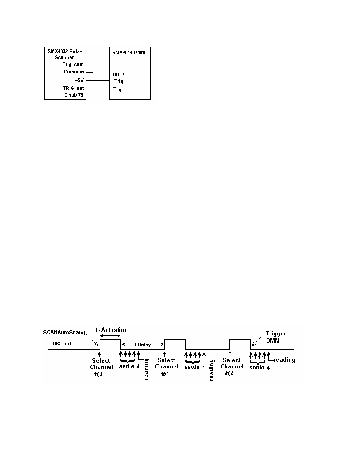
measurements following each channel selection.
ggered to take from the computer, whereby the Scanner selects channels from its Scan List table, and the DMM is tri
Figure 4-19. Trigger interfacing to an SMX2040 class of DMMs.
4.15.2 Multiplexing w th M 40 DMMs
For two wire measurements, the SMX2040 DMM must be connected to the A-Bus or the scanner, or to b
Bus and
sy
c
wiring capacitance. The latter will varies with the type of measurement. For insta
Ohms measurements the DMM current source level could contribute significant delay due to the c
time. For example, with 1,000pf cable capacitance,
range, is 0.1µA which translates to 33ms (dt = C*dV/I). It is also recommended to set the appropriate n
settling measurements for the DMM (a minimum of 4 is recommended regardless of measurement
C-Bus for 4-Wire measurements (assuming an SM4040 or SM4042 scanner). It is important to consider
stem settling time when making measurements. Time delays exist in any measurement system. These delays are
ontributed by various sources. These include the scanner’s relay actuation times, the DMM input settling and
ith e S X20
oth, the A-
nce, when making high value
apacitance charge
the source current of the SMX2044 DMM using the 33MΩ
umber of
rate).
4.15.3 Interface Commands and Timing
The sequence requiring the SMX2040 DMM to make triggered measurements generated by the SMX4032 starts
with the preparation of the SMX4032. Set the SMX4032 desired configuration, with Trigger Output enabled and
positive polarity. Each channel selection will generate a positive pulse with duration equal to the actuation time.
This could be generated by one of the scanning. The SMX2040 must be set up for triggered readings by using the
DMMSetTrigRead() command. In the following VisualBasic® example, the SMX2040 sends readings during the
scan. Since it’s on board FIFO is limited to 5 readings, and the DMM must continue to send all readings during the
scan, it is important to have a tight loop that reads the measurements fast enough so that no overrun error occurs.
Refer to Figure 4-13 for proper trigger connection.
SCANTriggerOutState(nScan, Enabled, PosEdge) // Set trigger output to Positive edge.
nReadings = 100 // Total number of measurements to take
DMMSetTrigRead(nDmm, 4, nReadings, NegEdge) // Total of 100 readings and 4 settling readings
SCANAutoScan(nScan, nSteps) // Start auto scan
For I = 0 to nReadings -1 // read values as they come
while(DMMReadMeasurement(nDmm, reading) = NO // wait for each reading and store it
Next
SCANOpenAllChannels(nScan) // Good idea to open all channels when done
Figure 4-20. Triggered reading process and timing of SM4042 Scanner and an SMX2044 DMMs.
Unlike the previous example, DMMSetBuffTrigRead() is not time critical since the DMM saves all
measurements to it’s on-board buffer, which is read after the scan is complete. However, this function
is limited to a maximum of 64 readings per scan.
SCANTriggerOutState(nScan, Enabled, PosEdge) ‘ Set trigger output to Positive edge.
nReadings = 50 ‘ Total number of measurements to take
Artisan Technology Group - Quality Instrumentation ... Guaranteed | (888) 88-SOURCE | www.artisantg.com
43 Signametrics
Page 45

MMSetBuffTrigRead(nDmm, 4, nReadings, NegEdge) ‘ Use 4 settling readings each
D
CANAutoScan(nScan, nSteps) ‘ Set off AutoScan
S
While DMMReady(nDmm) = NO ‘ wait for the DMM to indicate completion
end
W
For I = 0 to nReadings -1
while(DMMReadBuffer(n
‘ read values stored in the buffer
Dmm, reading(I)) ‘ Store each reading
Next
SCANOpenAllChannels(nScan) ‘ Good idea to open all channels when done
While SCANReady(nScan) = NO ‘ Since AutoScan is a polled operation,
DoEvents ' Make sure Scanner is ready
Wend
There are several SMX2040 family commands to considered for this operation:
DMMSetTrigRead(), DMMSetBuffTrigRead(), DMMReadMeasurement(), DMMReady(),
DMMReadBuffe
r() and DMMReadBufferStr().
Referrin
than t-Delay, for letion of the measurem e selection of the next channel.
g to figure 4.20, the total time it takes the DMM make a reading must be set to be shorter
comp ents prior to th
Signametrics 44
Artisan Technology Group - Quality Instrumentation ... Guaranteed | (888) 88-SOURCE | www.artisantg.com
Page 46

5.0 SMX2040 DMM Windows Interface
5.1 Distribution Files
The main directory of the distribution diskette DMM software.
Before installing the DMM or software, read the “Quick Install” page carefully. To install this software, enter the
command "A:SET un Program"
SETUP.EXE file name from the File Explorer te are compressed,
and must be installed using the SETUP program.
he SMX2040 DLL is a protected-mode Microsoft® Windows™ DLL that will control the Signametrics DMM. It
T
is pr application to demonstrate the DMM and the interface to the
ovided with a sample Visual Basic™ front-panel
LL ation about the files contained on the diskette. Some important
. Check the README.TXT file for more inform
D
files to note are:
UP" in the "R menu of the Windows File Manager; or double-click on the
File Description
SM40CAL.DAT
SM204032.LIB
contains the Microsoft® Windows™ SMX2040
Tool Manager window. Most files on this disket
Configuration file containing calibration information for each DMM
Do not write into this file unless you are performing an external
calibration! This file is normally placed at the C:\ root directory by the
setup program, and should be left there. It may cont
records for several DMMs.
The Windows import library. Install in a directory pointed to by your
LIB environment variable.
ain calibration
.
SM204032.DE
SM204032.DLL
SM204032.H
UserDMM.H
Msvbvm50.d
SM2044.vbw
SM2044.frx
SM2044.frm
F
ll
SMX2040 driver DLL module definition file.
The 32 bi
directory, in the Windows syst
PATH. Th installation progra
system directory (usually C:\WINDOWS\SYSTEM for Win98/95 or
at C:\WINNT\SYSTEM32 for Windows NT).
Driver
prototypes for the DLL, constant definitions, and error codes. Install in
a directory pointed to by your INCLUDE environment variable.
Header file contain
definitions to be used with the various measur
Visual Basic run-time interpreter. Usually, install in your
C:\WINDOWS\SYSTEM (or equivalent) directory. If it is not already
installed, run Msvbvm50.exe for proper extraction and registration.
Visual Basic project file
Visual Basic binary form file
Visual Basic file with main form
t driver DLL. This should be installed either in your working
em directory, or in a directory on your
e m installs this file in your Windows
header file. Contains the definitions of all the DMM’s functio n
ing all of the necessary DMM’s function, range, rate
e and source functions.
SM2044.vbp
File Description
2044glbl.bas
Artisan Technology Group - Quality Instrumentation ... Guaranteed | (888) 88-SOURCE | www.artisantg.com
Visual Basic project file
Visual Basic file with all global DMM declarations
45 Signametrics
Page 47

SM2044.exe
Visual Basic DMM control panel executable
Msvcrt.dll System file. Installs in your C:\WINDOWS\SYSTEM
Windrvr.vxd
Win98/95 Virtual Device Driver. Installs by ‘setup’ in your
directory.
C:\WINDOWS\SYSTEM\VMM32 directory.
Windrvr.sys
Win NT Virtual Device Driver. Installs by ‘setup’ in your
C:\WINNT\SYSTEM32\DRIVERS directory.
Install.doc
Installation instructions in MS Word
5.1.1 The SM40CAL.DAT file
The SM40CAL.DAT file contains calibration information for the specific DMM is it included. It determines th
verall analog performance for that DMM. You must not alter this file unless you are performing an external
o
calibration of the DMM. This file may contain multiple records for more than one DMM. Each record starts w ith
header line, followed by calibration data.
card_id 10123 type 2044 calibration_date 06/15/1999 ; The identification should match the last digits of the SN
ad ; A/D compensation
72.0 20.0
v
dc ; VDC 330mV, 3.3V, 33V, 330V range
.0 0.99961
86
-3
0 .999991
-37.
-8
0 0.999795
3.
1.00015
-8
.8
vac
5
.303 ; starting with the 330mV range, and last line is for the 250V range.
0.84 1.015461 23
0.0043 1.0256 23
0.0 1.02205 0
0.0 1.031386 0
idc ; IDC 3.3mA to 2.5A ranges. 1
-1450.0 1.00103
-176.0 1.00602
-1450.0 1.00482
-176.0 1.0
ia
1.6
0
.0
1.69 1.00513
0.0 1.0142
2w-ohm ; Ohms 33, 330, 3.3k,...,330Meg ranges, offset and gain
12700.0 1.002259 ;in the SMX2040, the 1
1256.0 1.002307
110.0 1.002665
0.0 1.006304
0.0 1.003066
0
.0 1
0
.0
0.0 1.00030
…
; VAC 1st line - DC offset.
c ; IAC 3.3mA to 2.5A ranges, offset and gain
1.02402
1.03357
.001848
0.995664
Subsequent lines: 1
st
entry is offset, 2nd is gain parameter
st
s. 1
entry is Offset the 2nd is gain parameters
st
entry is Offset the 2nd is gain, 3rd freq. comp
st
and last lines are placeholders
.
.
first line identifies the DMM and the calibration date. The "card-id" is stored in ROM on each DMM.
The During
alization the
initi driv er reads information from the DMM hardware such as serial number, DMM type, and allocated
O space. Next it reads the corresponding calibration information from the SM40CAL.DAT file and makes sure
I/
there is compatibility between the hardware, the calibration rec
od and the software. If all is checked OK, it initialize
e
a
.
Signametrics 46
Artisan Technology Group - Quality Instrumentation ... Guaranteed | (888) 88-SOURCE | www.artisantg.com
Page 48

DMM hardware. DMMInit accepts the name and location of the calibration file. A qualified technician may
the
modify individual entries in the calibration file, then reload them using th
5.2 Using the SMX2040 Driver Wit
h C++ or Similar Software
e DMMLoadCalFile comma nd.
Install the SM204032.H and UserDMM.H header file in a directory th
for header files. This header file is known t
will need to convert the SM
mpiler.. Install SM204032.LIB
the co
SMX2040 software must be installed prior to running any executable code. Install the SM204032.DLL
where either your program will do a LoadLibrary call to load it, or on the PATH so that W
DLL au
In using the SMX2040 driver, first call DMMInit to read the ca
the DMM function. The DM
clearly indicate the fun
Two functions are
precision (double) re
All functions accept a D M er parameter, which must be set to the value nDmm, which w
DMMInit() fu
b ved as a string using ErrStr().
tomatically.
provided to return DMM readings. DMMRead returns the next reading as a scaled double-
nction. F DMMs this value will be 0,1,2..n. Most functions return an er
e retrie
204032.DEF an
M function constants are defined in
hey invoke. Use DMMSetRate to set the reading rate defined in the header file.
ction t
sult, and DMMReadStr returns the next reading as a formatted string ready to be displayed.
M -numb as returned by
or multiple ror code which can
DMM
Multiple Card Operations U er Windows
o work with Microso
d SM204032.LIB using ImpDef.exe and ImpLib.exe, provided with
in a directory that will be searched by the linker for import libraries. The
nd
at will be searched by your C/C++ compiler
ft Visual C++™. To compile using Borland, you
in a location
indows will load the
libration information. Call DMMSetFunction to set
the UserDMM.H header file, and have names that
Single .EXE operation
A g multiple DMMs from a single e cutable is the most common wccessin xe ay for running up to 10 DMMs using the
W s DLL. A combination of several SMX and SMX2044s can beindow 2040s cont
Thread) g comman
( is used to control all of th e units. Make sure that prior to issuin
mand to define the DMM to be accessed.
using DMMInit(). The nDmm parameter is passed with each DLL co
Since this configuration utilizes the DLL to service all DMMs, it must hand le a sin gle
ne at a e. For DMM pacitan
o tim example, when one reads DCV, and another reads Ca
reading the DCV be
Capacitance will dictate the measurement throughput. For improved performance, one can use the following:
fore it will proceed to take a Capacitance reading. Being a relatively slow measurement,
m
Multiple .EXE operation
By having several copies of SM204032.DLL, and renaming them, y
xecutables. For instance, having a copy named SM204032A.DLL i
e
two executable files, MultiExe0.exe and MultiExe1.exe, each of the executables will run independently, making
calls to the respective DLL. This can provide an execution throughput advantage over the method mentioned abov
If using VisualBasic, the MultiExe.exe source code should define nDmm = 0, and MultiExe1.exe should define
n
Dmm = 1. In addition, the first should declare the SM204032.DLL and the second should declare
SM204432.DLL:
MultiExe0.exe VB function declarations:
Declare Function DMMInit Lib "sm204032.dll" (ByVal calFile As String) As Long
Declare Function DMMRead Lib "sm204032.dll" (ByVal nDmm As Long, dResult As Double) As Long
NDmm = 0
MultiExe1.exe VB function declarations:
Declare Function DMMInit Lib "sm20432A.dll" (ByVal calFile As String) As Long
Declare Function DMMRead Lib "sm20432A.dll" (ByVal nDmm As Long, dResult As Double) As Long
NDmm = 1
/*
*************************
Exmp2040.C Exmp2040.EXE
*
*********************************************
ou can run multiple DMMs with separate
n C:\windows\system (Win98/95), and having
rolled, as long as the single .EXE
ds to any DMM, it is initialized
reading or control command
ce, the DLL must finish
e.
Artisan Technology Group - Quality Instrumentation ... Guaranteed | (888) 88-SOURCE | www.artisantg.com
47 Signametrics
Page 49

*
* A simple Windows .EXE example for demonstrating the SMX2040,44
* DMMs using "C"
* Sets Function to VDC, Range to 33V, rate to 10rps.
* Display five measurements using a Message box.
****
******************************************************************
*
* M
ake sure SM204032.lib is included in the libraries. For Microsoft
* Version 4.0 C++ and above, place under 'Source Files' in the
* Workspace, along side with Exmp2040.c
* PROJECT SETTINGS:
*
* /nologo /ML /W3 /GX /O2 /D "WIN32" /D "NDEBUG
* /FR"Release/" /Fp"Release/Exmp2
*
opy both SM204
* C 032.DLL and SM204032.LIB to the project directory.
*
*******************************************************************/
****
efine WINAPI __stdcall
// #d
lude <windows.h>
#inc
lude <string.h>
#inc
f _Windows
#ifde
#define _W
if
#end
lude "sm204032.h"
#inc // functions declarations and error codes.
lude "UserDMM.h"
#inc // All functions, range and rate info and function declarations.
ain(void){
int m
// Address first DMM in the system
char
,"C:\\sm40cal.dat"); // initialize SMX2044, and read calibration file
alization ERROR !", "Startup SM204032 DLL",MB_OK); // Error
m,VDC); // Set to DCV function
,_30V); // and to 33V range
E_10); // 60 samples per sec
// Clear string store
// take 5 readings
DMMReadStr(nDmm, ead); // read
strcat(strMsg,Read); // Append each reading
// insert space between readings
DC",MB_OK); // Show readings
}
INDOWS
int I, nDmm = 0;
char Read[16];
strMsg[256];
i = DMMInit(nDmm
if(i<0)
MessageBox(0,"Initi
DMMSetFunction(nDm
DMMSetRange(nDmm
DMMSetRate(nDmm,RAT
strcpy(strMsg,"");
for(i=1; i<= 5; i++){
strcat(strMsg," ");
}
MessageBox(0,strMsg, "SM204032.DLL Read Resistance & V
return 0L;
040.pch" /YX /Fo"Release/" /Fd"Release/" /FD /c
R
" /D "_CONSOLE" /D "_MBCS"
5.3 on Pane App
Visual Basic Fr t l lication
The e control panel for the SMX2040 DMM.
Visual Basic front panel application, SM2044.EXE, is an interactiv
Dur he hardware before the front panel is
ing loading, which takes a few seconds, it initializes and self calibrates t
displ
ayed.
The abeled V, I, etc. control the DMM function. As you push a function, the front panel application
push buttons l
will sw ge an de is selected by pushing the AutoRange
itch the DMM to the selected ran d function. A utorange mo
chec the D me state prior to operation. (This is an
k box. The S-Cal r t MM, leaving the DMM in the sa
inte er t from d ards and writes to the
rnal calibration only. It is diff en the external calibration, which uses external stan
SM rrect fo e to changes in operating
40CAL.DAT file. S-Cal is used to co internal offset a
temp
erature).
box ecalibra es
The eq. and per check boxes are context sensitive and appear in ACV and ACI. When freq. is enabled, the
fr
frequency and amplitude are shown at the same time. In this mode, the reading rate
per is enabled, the period is shown. The SMX2044 panel has additional capabilitie
SMX2040 is detected.
Signametrics 48
Artisan Technology Group - Quality Instrumentation ... Guaranteed | (888) 88-SOURCE | www.artisantg.com
r any nd gain drifts du
is slower than indicated. When
s, which are disabled if an
Page 50

he source code file GLOBAL.BAS (in the V_BASIC directory of the distribution diskette) contains the function
T
declarations and the various ranges, rates and other parameters, which are required. These definitions are th
uplicates of the “C” header files required to write Visual Basic applications which interact with the driver DLL,
d
along wi ables required for this particular front-panel application.
th some global vari
e
3 Basic Simple Application
5. .1 Visual
The le panel application for VisualBasic that includes two files, Global.Bas and
following is a simp
Sim P ontains two objects; a Text Box to display the DMM readings, and a
ple anel.frm. It has a panel that c
Com a ding trigger.
m nd Button that acts as a rea
Glo .b contents:
bal as module file
Option Explicit
' Declare all functions we are going to be using: From SM204032.H file.
Declare Function DMMInit Lib "sm204032.dll" (ByVal nDmm as long, ByVal calFile A
Declare Function DMMSetRate Lib "sm204032.dll" (ByVal nDmm As Long, ByVal nR
Declare Function DMMSetFunction Lib "sm204032.dll" (ByVal nDmm As Long, ByVal nFunc As Long) As Long
Declare Function DMMSetRange Lib "sm204032.dll" (ByVal nDmm As Long, ByVal nRange As Long) As Long
Declare Functi
' Definitions from UserDMM.H
' for DMMSetFunction()
Global Const VDCFunc = 0
Global Const VACFunc = 4
Global Const Ohm2Func = 21
Global nDmm as Long
' for DMMSetRange()
Global Const Range0 = 0
al Const Range1 = 1
Glob
al Const Range2 = 2
Glob
al Const Range3 = 3
Glob
'for DMMSetRate(): Rea
Global Const RATE_5 = 5 '5 rps
Global Const RATE_10 = 10 '10 rps
Global Const RATE_30 = 30
bal variables
'Glo
al nDmm As Long ' Globa
Glob l store for the DMM number
on DMMRead Lib "sm204032.dll" (ByVal nDmm As Long, dResult As Double) As Long
ding rates
s String) As Long
ate As Long) As Long
S anel.frm Form file contents: impleP
Private Sub Form_Load() 'Fomr_Load allways gets executed first.
Dim i As Long
nDmm = 0 ‘Set to first DMM in the system
i = DMMInit(nDmm,"C:\sm40cal.dat") 'Initialize and load cal file
i = DMMSetFunction(nDmm, VDCFunc) 'Set DMM to DCV function
i = DMMSetRange(nDmm, Range2) 'Select the 33V range
i = DMMSetRate(nDmm, RATE_10) 'Set measurement rate to 10 rps
End Sub
Private Sub ReadBotton_Click() 'Read Botton Click action.
Dim i As Long 'Any time this botton is pressed
Dim dReading As Double 'the DMM takes a reading and displays it.
i = DMMRead(nDmm, dReading) 'Take a reading
TextReading.Text = dReading 'display it in a Text box.
End Sub
5.4 Windows DLL Default Modes and Parameters
Artisan Technology Group - Quality Instrumentation ... Guaranteed | (888) 88-SOURCE | www.artisantg.com
49 Signametrics
Page 51

fter initialization, the Windows DLL default modes and A
• Autoranging: Off
• Function: DC Volts
• Range: 330V
•
Relative: Off
• Synchronized Mode: Off
• Measurement rate: 10 rps
• Temperature units are set to
•
Offset Ohms: Off
AC Caps level: 0.45V
•
Peak.
parameters on your DMM are set up as follows:
°C
5.5 Using MX2040 DLL with LabWindow
the S s/CVI®
When using the SMX2040 DLL wi ou should read the LabWin.txt file included with the
software diskette.
th LabWindows/CVI, y
An example appl SMX2040 DLL calls from LabWindows/CVI ® is shown below. It
contains funct e_ohms() and measure_vdc(), with sample calls to the SMX2 040.
NOTE: Although these me
Test Executive, they are no
/* function: measure_ohms
int measure_ohms(double
short ret, i;
DMMSetFunction
DMMSetAutoRan
/* to settle auto-ra
for( i = 0 ; i < 4 ; i+
return ret;
}
/* function: measure_vdc, purpose: measure DC Volts */
int measure_vdc(double Vr
short ret, i;
DMMSetFunction
DMMSetAutoRan
/* to settle auto-ra
for( i = 0 ; i < 4 ; i+
return ret;
}
ication of
ions measur
asurement functions use LabWindows/CVI® and the LabWindows/CVI(R)
t necessarily coded to LabWindows® instrument driver standards.
, purpose: measure 2-wire ohms */
OHMreading) {
s (0, OHMS2W);
ge (0, TRUE);
nge and function changes ignore three readings */
+ ) ret = DMMReadNorm (0, & OHMreading);
eading) {
s
(0, VDC);
ge (0, TRUE);
nge and function changes ignore three readings */
+ ) ret = DMMReadNorm (0, &Vreading);
Signametrics 50
Artisan Technology Group - Quality Instrumentation ... Guaranteed | (888) 88-SOURCE | www.artisantg.com
Page 52

5.6 Windows Command Language
The following section contains detailed de se
commands that pe y the SM204 ither
be retrieved as a st g DMMErrStri
UserDMM.H file ll the pertinen
for the various functions is based on “C” f s DLL containing
these functions as int values to b c long type). TRUE
1 and FALSE i is also differe .
is
rtain to onl
ring usin
contains a
sumes all
s 0 (which
scriptions of each function of the Windows command language. Tho
0 are indicated. Most functions return an error code. The code can e
ng function, or looked up in the SM204032.H header file. The
t definitions for the DMM ranges functions etc. The following description
unction declarations. Keep in mind that the Window
e windows 32bit integers (corresponds to VisualBasi
nt from VisualBasic where True is –1 and False is 0)
DMMArmAnalogTrigger
SMX20
40 ;
SM
X20
44
;
Description r
Remarks This function is usable for VDC, VAC, Ohms, IAC, and IDC. Setup the
The dThresh value is in base units, and must be within the DMM range setting . For
Arm DMM fo analog level trigger operation.
#include
int DMMArmAnalogTrigger(int nDmm, int
analog level trigger operation. Foll
easure
m ments continuously, waiting for a value which
When this occurs, a trigger is produced with identical processing as in
ArmTrigger. Threshold crossing sense is determined by the first measurement
DMM
following the call o
set threshold, dThresh
DMM. If the first measurement is greater th
smaller than dThresh will trigger. For exam
reading after arming the D
the DMM. On the other hand, i
the DMM is 0.500000 V, then 1.000001 V (or gre
example, in the 330 mV range, dThresh must be within -0.330000 and +0.330000. In the
33 kΩ, range dThresh must be between 0.0 and 33.0e3.
Following an analog level trigger event, the DMM makes iSamples readings at the set
function, range, and reading rate, and stores them in an internal buffer. Autoranging is
not allowed when using DMMAnalogTrigger. Between the time the
DMMArmAnalogTrigger is issued and the time the buffer is read, no other com
should be sent to the DMM. One exception is the DMMDisArmTrigger command.
"sm2
04032.h"
iSamples, double FAR *dThresh)
SMX2040 for
owing reception of this command the DMM makes
exceeds the threshold, dThresh.
f DMMArmAnalogTrigger. If that measurement is lower than the
, subsequent measurements greater than dThresh will trigger the
an dThresh, subsequent measurements
ple, if dThresh is 2.00000 V and the first
MM is 2.500000 V, then 1.999999 V (or smaller) will trigger
f dThresh is 1.000000 V and the first reading after arming
ater) will trigger the DMM.
mand
Use the DMMReady to monitor when the DMM is ready. When ready, you
read up-to iSamples, using DMMReadBuffer or DMMReadBufferStr
functions. Once DMMReady returns TRU
E, it should not be used again prior to
reading the buffer, since it prepares the buffer for reading when it detects a ready
dition.
con
can
Artisan Technology Group - Quality Instrumentation ... Guaranteed | (888) 88-SOURCE | www.artisantg.com
51 Signametrics
Page 53

terParame Type/Description
nDmm
iSamples
dThresh
eturn Value e retu
R Th rn value is one of the following constants.
Meaning
Value
DMM_OKAY
Negativ
Example
DMMArmAnalogTrigger(0,64,1.5);
for(i=0; i < 64 ; i++)
Buffer[i] = DMMReadBuffer(0);
DMM ger
ArmTrig
SMX2040 ; SMX2042
Description
e value
double Buffer[64];
while( ! DMMReady(0));
; SMX2044 ;
Arm DMM for external trigger operation.
#include "sm204032.h"
int DMMArmTrigger(int nDmm
int Identifies the DMM. DMMs ar
int The num
This number must be between 1 and 64, inclusive.
double FAR Analog level trigger thresh
Ope
ration successfully terminated
Error code.
ber of samples the DMM takes following a trigger pulse.
, int iSamples)
e numbered starting with zero.
old value
Remarks
Setup the SMX2040 for external hardware trigger operation. Following reception of this
command, the DMM enters a wait state. After reception of an external trigger pulse, the
DMM makes iSamples readings at the set function, range, and reading rate; and stores
them in an internal buffer. No autoranging is allowed for external trigger op eratio n
Between th
other command should be sent to the DMM. One exception is the DMMDisarmTrigger
com
Use the DMMR
reading of iSamples). When ready, you can read up to iSamples, using
DMMReadBuf
TRUE, it shoul e it prepares the buffer
for reading when it detects a ready condition.
Parameter
nDmm
iSamples
e time the DMMArmTrigger is issued and the time the buffer is read, no
mand. This function is usable for VDC, VAC, Ohms, IAC and IDC
eady to monitor when the DMM is ready (following trigger and the
fer or DMMReadBufferStr functions. Once DMMReady returns
d not be used again prior to reading the buffer, sinc
Type/Description
int Identifies the DMM. DMMs are numbered starting with zero.
int The number of samples the DMM takes following a trigger pulse.
This numb
er must be between 1 and 64, inclusive.
.
Return Value The return value is one of the following con
Signametrics 52
Artisan Technology Group - Quality Instrumentation ... Guaranteed | (888) 88-SOURCE | www.artisantg.com
stants.
Page 54

Value Meaning
DMM_
Negative Value
Exa
mple double Buffer[64];
DMMArmTrigger
for(i=0; i < 64 ; i++)
Buffer[i] = DMMReadBuffer(0);
DMMBurstBu
; SMX2042
Description Setup the DMM for Triggered operation.
Remarks
OKAY
while( ! DMMReady(0));
ffRead
; SMX2044 ; SMX2040
#include "sm204032.h"
#include "UserDMM.h"
int DMMBurstBuffRead(int nDmm, int iSettle, int iSamples)
Following reception of this command the DMM enters a burst read mode, where it takes
iSettle + 1 readings at the set measurement function, range, and reading rate; and saves
the last reading to the on-board buffer. This process repeats for iSamples. No other DM
command should be issued to the DMM until the it completes the operation, and the
buffer is read. One exception is the DMMDisarmTrigger command, which terminates
the process. No autoranging is allowed in this mode. This function is usab le for VDC,
VAC, Ohms, IAC, IDC, and RTD measurements. Measurement rate should be set to
10rps or higher. The total time it takes to complete this process is equal to iSamples * (
iSettle + 1) / (measurement rate).
Use the DMMReady to monitor if the has completed the operation, and is ready. When
ready, read up to iSamples, using DMMReadBuffer or DMMReadBufferStr functions
Once DMMRead
since it clears som
dition.
con
Operation successfull inated
Error code.
(0,64);
y returns TRUE, it should not be used again until the buffer is read,
e flags in preparation for buffer read
y term
M
.
ing when it detects a ready
Type/Description
Parame
iDmm
iSettle
iSamples
Return Value The return valu he following constants.
Value
DMM_OKAY
Negative Value
Example
Artisan Technology Group - Quality Instrumentation ... Guaranteed | (888) 88-SOURCE | www.artisantg.com
ter
Meaning
double Buffer[50];
int Identifies the DMM. DMMs are numbered starting with zero.
int The number of settling measurements prior to read value. Mu
set between 0 and 250. Recommended value is 4.
int The nu
number of trigger pulses. This num
inclusive.
e is one of t
Operation successfully terminated
Error code.
mber of samples the DMM takes following the same
ber must be between 1 and 64,
53 Signametrics
st be
Page 55

DM stBuffRead(0, 4, 50); // 4 settling readings for
Buffer[i] = DMMReadBuffer(0);
MBur each
// measurement, and take 50 readings
ile( ! DMMReady(0) ); // wait for completion
wh
o f r(i=0; i <
// on-board b
50 ; i++) // read 64 readings from DMM’s
uffer
DMMBurstRead
SMX2040 ; SMX2042
; SMX2044 ;
Description Setup the DMM for multiple read
come.
#inc
lude "sm2
lude "User
#inc
int DMMBurs
Remarks Set the DMM to take multiple measurements, sendi
This function is e DMMSetTrigRead function, with the exception that it
does not wait for a hardware trigger to start making measurements. Following reception
of this c
at the se
computer. This process repeats for
until iSa
using the DMMReadMeasurement command as fast as they become available
will prevent an Overrun communication error, which is an indicatio n that the ra
which measurements are read from the bus do not keep up with the DMM transmission.
The DMM has five readings FIFO to lessen this problem. No autoranging is allowed in
this mode. This function is usable for VDC, VAC, Ohms, IAC, IDC, and RTD
measurements. Measur
plete this process is equal to iSamples * ( iSettle + 1) / (measurement rate).
to com
Use the DMMRead
read the data. Read as many samples as iSamples to guarantee proper conclusion of this
capture process.
04032.h"
DMM.h"
tRead(int nDmm, int iSettle, int iSamples)
similar to th
omman burst read mode, where it takes iSettle + 1 readings
d the DMM enters a
t measu n, range, and reading rate; and sends the last reading to the
rement functio
mpels ements are read, it is necessary to read the samples from the DMM
measur
ement rate should be set to 10rps or higher. The total time it takes
Measurement to monitor when reading becomes available, and to
ings operation, sending back measurements as they
iSamples. Following the issue of this command, and
ng readings back to the computer.
. This
te at
Parame
nDmm
iSettle
iSamples
Return Value The return valu
Value
DMM_OKAY
Negative Value
Example double Reading
DMMBurstRead(0, 10, 250); // settle 10 reads., 250 samples
Type/Description
ter
int Identifies the DMM. DMMs are numbered st
int The number of settling measurements prior to read value. Must be
set between 0 and 250. Recommended value is 4.
Meaning
for(i=0; i < 250 ; i++) // read 250 meas. as they come
int The number of samples the DMM takes following the sam
number of trigger pulses. This number must be between 1 and 32,000,
inclusive.
e is one of the following constants.
Operation successfully terminated
Error code.
[250];
arting with zero.
e
Signametrics 54
Artisan Technology Group - Quality Instrumentation ... Guaranteed | (888) 88-SOURCE | www.artisantg.com
Page 56

while( ! DMMReadMeasurement(0 , Reading[i]) );
DMMCalibrate
SMX2040 ; SM 2
X2042 ; SMX 044 ;
Descriptio Internally calibrates the DMM.
int DMMCalibrate(int nDmm)
Remarks his function re-calibrates the DMM, and return s it to the current operating mode.
Return Value owing constants.
Example status = DMMCalibrate(0); /* a quick internal cal.*/
Comments d is the same as the S-Cal command in the
DMM lay
SMX2040
n
"sm204032.h"
Type/Description
L
T
Parameter
nDmm
Value
Meaning
DMM_OKAY
Negativ
e Value
#include
The return value is one of the foll
This performs an internal DMM calibration an
VB Control Panel. It is not related to the external calibration represented in the
SM40CA .DAT file.
CleanRe
; SMX2042 ; SMX2044 ;
int Identifies the DMM. DMMs are numbered starting with zero.
DMM is OK.
r
Erro
Des an specified relay.
cription Cle
#include "sm204032.h"
int DMMCleanRelay(int nDmm, int iRelay, int iCycles)
Remarks This function cleans iRelay by vibrating the contact iCycles . This function is useful for
removing oxides and other depos
are particularly sensitive to K2 contact resistance and therefore shou ld be cleaned
periodically. It is also useful for making sound in computer without a speaker.
Parameter
iRelay
iCycles
nDmm
Return Value Integer error code..
Value
Type/Description
int The relay to clean. 1 for K2, 2 for K2 and 3 for K3.
int The numer of times the relay contac is shken. 1 to 1000.
int Identifies the DMM. DMMs are numbered starting with zero.
Meaning
its from the relay contacts. DC Current measurements
Artisan Technology Group - Quality Instrumentation ... Guaranteed | (888) 88-SOURCE | www.artisantg.com
55 Signametrics
Page 57

DMM_OKAY
Operation su
ccessfully completed.
Negativ
Exa int status = DMMCleanRelay(0, 2, 100); // Shake K2 1000
mple
e Value
Error code
DMMClearMinMax
SMX2040 ; ; SMX2044 ;
escription e.
D Clears the Min/Max storag
int DMMGetMin(int nDmm)
Remarks This function clears the Min/Max values, and initiates a new Min/Max accumulation. See
Return Value Integer error co
SMX2042
Param
nDmm
Value
#include "sm204032.h"
MGetMin
DM for more details.
eter
Type/Description
int Identifies the DMM. DMMs ar
de..
Meaning
e numbered starting with zero.
Ope sfully completed.
DMM_OKAY
Negativ
xample int status = DMMClearMinMax(0);
E
e Value
ration succes
Error code
DMMClosePCI
SMX2040 ; ; SMX2044 ;
Description pecified DMM. Not for user applications.
#include "sm204032.h"
int DMMClosePCI(int nDmm)
Remarks
R
eturn Value Integer error code.
SMX2042
Parameter
nDmm
Close the PCI bus for the s
This function is limited for servicing the DMM. It has no use in normal DMM operation.
See also DMMOpenPCI() function.
Type/Description
int Identifies the DMM. DMMs are numbered starting with zero.
Value
Meaning
DMM_O
KAY
Signametrics 56
Artisan Technology Group - Quality Instrumentation ... Guaranteed | (888) 88-SOURCE | www.artisantg.com
Operation
successfully completed.
Page 58

Negative Value
Error code
Example int status = DMMClosePCI(0);
DMMDelay
SMX2040 ; SMX2042 ; SMX2044 ;
Description Wait for a given time.
#include "sm204032.h"
int DMMDelay(double dTime)
Remarks een 0.0 and 100.0
Parameter
dTime
R
eturn Value The return value is one of the following constants.
Value
DMM_OKAY
N
Example lay(1.2); /* wait for 1.2 Sec */
Delay of dTime seconds. dTime must be a positive double number betw
seconds.
Type/Description
double Delay time in seconds.
Meaning
Operation successfully terminated
Error
egative Value
code
DMMDe
DMMDisableTrimDAC
SMX2040 SMX2042 ; SMX2044 ;
Description f the Trim DAC.
int DMMDisableTrimDAC(int nDmm)
Terminate the operation o
#include "sm204032.h"
Remarks
Parame
nDmm
Return Value
Integer error code.
Value
DMM_OKAY
Artisan Technology Group - Quality Instrumentation ... Guaranteed | (888) 88-SOURCE | www.artisantg.com
This function disables the Trim DAC. Since usage of the Trim DAC consumes a lot of
the on-b
not in use. See DMMSetTrimDAC, DMMSetDCVSource and DMMSetACVSource
more details
for .
ter
Type/Description
Meaning
oard microcontroller’s resources it must
int Identifies the DMM. DMMs are numbered starting with zero.
Operation successfully completed.
57 Signametrics
be turned off with this function when
Page 59

Erro
r code
Example
Negative Value
DMMDisableTrimDAC(0); // Remove Trim DAC from operation
DMMDisArmTrigger
SM ;
X2040 ; SMX2042 ; SMX2044
Description Abort trigger operation.
int DMMDisArmTrigger(int nDmm)
Remarks his function sends the DMM a trigger termination command. If the DMM is waiting
T
for a trigger, it will exit the wait mode, and be ready for a new operation . I
following an external hardware or analog level trigger arm command
(DMMArmAnalogTrigger, DMMArmTrigger, or DMMTrigger ). It can be used
with no limitation.
t can be used
Parameter
nDmm
Return Value code
Integer error
Value
DMM
Negat
Type/Description
int Identifies the DMM. DMMs are numbered starting with zero.
gMeanin
_OKAY
ive Value
Operation successfully completed.
code
Error
DMMDu
tyCycleStr
SMX2040 SMX2042 ; SMX2044 ;
Description ng format.
int DMMDutyCyc
Remarks This function is the string version of DMMReadDutyCycle. The
Return percent duty cycle of an AC signal in stri
#include "sm204032.h"
leStr(int nDmm, LPSTR lpszReading)
stored at the location pointed to by lpszReading. See DMMReadDutyCycle
details.
measurement result is
for more
Parame
nDmm
lpszRead
Return Value
Value
DMM_OKAY
ter
Type/Description
ing
The return value is one of the following constants.
Meaning
Signametrics 58
Artisan Technology Group - Quality Instrumentation ... Guaranteed | (888) 88-SOURCE | www.artisantg.com
int Identifies the DMM. DMMs are numbered starting with zero.
LPSTR Points to a buffer (at least 16 characters long) to hold t
result.
Valid return.
he
Page 60

Negative Va
lue
Error code
Example char cBuf[17]
; int status = DMMDutyCycleStr(0, cBuf);
DMMErrString
SMX2040 ; S ; SMX2044 ;
Description Return the string the error code.
Remarks tion re g containing the error description which corresponds to the
MX2042
Parameter
iErrorC
iBuffLength
lpszError
ode
describing
#includ
int DMMEr ring(int iErrorCode, LPSTR lpszError, int
This func
iErrorCo
e "sm20
Type/Description
4032.h"
rSt iBuffLength)
turns a strin
de. The error string is placed at lpszError.
int Error code.
int The maximum available length of the string buffer
LPSTR Points to a buffer (at least 16 characters long) to hold the
error string.
Return Value The return value is the length of the error string or one of the following constants.
Meaning
Value
Negative Value
Error code
Example char cBuf[48];
int length = DMMErrString( -3, cBuf, 48);
DMMFrequencyStr
SMX2040 SMX2042 ; SMX2044 ;
Description Return the next DMM frequency reading, formatted for printing.
#include "sm204032.h"
int DMMFrequencyStr(int nDmm, LPSTR lpszReading)
Remarks This function makes frequency measurement and returns the result as a string formatted
for printing. The print format is fixed to six digits plus units, e.g., 05.001 Hz. If the
DMM is in autorange, be certain to take an amplitude reading before using this
command. It may take several calls to DMMFrequencyStr() to get the measured
frequency, because the DMM frequency counter uses a frequency ranging scheme which
gets activated only when a frequency or period reading function is received. If the
previously measured frequency was 1 Hz and the frequency being measured is 300 kHz
(or vise versa), it might take as many as six calls to DMMFrequencyStr() or any of the
other frequency measurement functions, to read the correct frequency. This function is a
Secondary function which requires the DMM to be in either VAC or IAC function and
at the appropriate range.
Artisan Technology Group - Quality Instrumentation ... Guaranteed | (888) 88-SOURCE | www.artisantg.com
59 Signametrics
Page 61

Parameter Type/Description
nDmm
lpszRead
ing
Identifies the DMM. DMMs are numbered starting with zero.
int
LPSTR Points to a buffer (at least 16 characters lo
converted
result.
Return Value The return value is one of the following constants.
Meaning
Value
DMM_
DMM_
Negative Va
OKAY
CNT_RNG
lue
Example char cBuf[1
Operation successfully completed.
Frequency counter is over or under range.
Error code
7];
int status;
atus = DM
st MFrequencyStr(0, cBuf);
ng) to hold the
Signametrics 60
Artisan Technology Group - Quality Instrumentation ... Guaranteed | (888) 88-SOURCE | www.artisantg.com
Page 62

DMMGetACCapsR
SMX2040 SMX2042 SMX2044
;
Description Return the resist
#include "sm204032.h"
int DMMGetACCapsRint nDmm, double *lpdResult)
Remarks This function retrieves the resistance value from las
measurement. It perform ing and conversion required, and returns the result as a
64-bit double-precisi point number in the location pointed to by lpdResult.
Returned resul
section
Parameter
nDmm
lpdResult
urn Value The re
Ret turn value is one of the following constants.
Meaning
Value
DMM_OKAY
Negative Value
4.8 of this ma
Type/Description
ance component of the last AC Caps measurement.
t reading of AC based Capacitance
s all scal
on floating-
t is a val rcuit Capacitance Measurements in
ue in ohms. Read about In-Ci
nual.
int Identifies the DMM. DMMs are numbered starting with zero.
double * Points to the location to hold the resistance value.
DMM initialized successfully.
Error code
Over range occurred, implying a very high parallel resistance value.
Example
OVER_RNG
double d;
int status;
stat MGetACCapsR(0, &d);
us = DM
DMMGetBusInfo
SMX2040 ; SMX2042 ; SMX2044 ;
Description
Remarks This function reads the PCI bus and slot numbers of the selected DMM. It provides
Returns the PCI Bus and Sl ot numbers for the selected DMM.
int DMMGetBusInfo(int nDmm, int *bus, int *slot)
means to relate the physical card locat
a DMM in the PCI system tree. This function actually scans the hardware rather then
look up the information in the registry.
ion to the nDmm value by detecting the location of
Artisan Technology Group - Quality Instrumentation ... Guaranteed | (888) 88-SOURCE | www.artisantg.com
61 Signametrics
Page 63

Parameter Type/Description
nDmm
bus
slot
Return Value The return value is one of the following constants.
Meaning
Value
DMM_OKAY
Negative number
Example int bus, slot; // Find on which bus, and slot the DMM is at
DMMGet alDate(3,
int Identifies the DMM. DMMs are numbered starting with zero.
int *
a pointer to integer at which the bus number is stored (0 to 255)
int * A pointer to a
15)
Operation was successful.
Error code
C &bus, &slot); // DMM#3
n integer where the slot number is stored (0 to
DMMGetCalDate
MX2040 ; SMX2042 ; SMX2044 ;
S
Description Retu
rn the calibration date string from the DMM.
int DMMGetCalDate(int nDmm, LPSTR lpszCalDate)
Remarks ibration date string from the structure.
Parameter
nDmm
lpszCalD
eturn Value The return value is one of the following constants.
R
Value
any positive number
Negativ
Example char cBuf[1
DMMGet
SMX2040 ; SM 2
dB
X2042 ; SMX 044 ;
This function reads the cal
Type/Description
int Identifies the DMM. DMMs are numbered starting with zero.
ate
Meaning
e number
int status;
status = DMMGetCalDate(0, cBuf);
LPSTR Points to a b
cal date string.
Length of the date string
Error code
6];
uffer (at least 16 characters long) to hold the
Descriptio Get dB deviation from the reading at the time relative was activated.
n
#includ
Signametrics 62
Artisan Technology Group - Quality Instrumentation ... Guaranteed | (888) 88-SOURCE | www.artisantg.com
e "sm204032.h"
Page 64

int DMMGetdB(int nDmm, double FAR *lpdDev)
Remarks ble floating value that is the dB deviation relative to the
Parame
nDmm
lpdDev
Return Value Integer error code..
Value
DMM_OKAY
Negative Value
This function returns a dou
re
ading made just before the relative function was activated. This function is useful in
determining measurement errors in dB. It can be used fo
DC evaluation.
Type/Description
ter
int Identifies the DMM. DMMs are numbered starting with zero.
double FAR * Pointer where the dB value is to be saved.
Meaning
Operation successfully completed.
Error code
r bandwidth measurements or
Example double FAR dB; int status = DMMGetdB(0, &dB);
DMMGetdBStr
X2040 ; SMX2044 ; SM
Description Get dB deviation from the readin g at the time relative was activated.
include "sm204032.h"
#
Remarks This function is the same as the DMMGetdB(), with the exception that it returns a string.
Parameter
nDmm
lpszDB
Return Value Integer string length if successful, or an error code..
Value
int DMMGetdBStr(int nDmm, LPCSTR lpszDB)
See DMMGetdB() for more details.
Type/Description
int Identifies the DMM. DMMs are numbered starting with zero.
LPCSTR Points to a buffer (at least 16 characters long) to hold th e
resu
lt. The return value will consist of a leading sign a floatin g-point,
and a ‘dB’ units specifier
Meaning
Negative Value
Example char cBuf[32]; int strLength = DMMGetdBStr(0, cBuf);
DMMGetCJTemp
SMX2040 ; SMX2042 ; SMX2044 ;
Artisan Technology Group - Quality Instrumentation ... Guaranteed | (888) 88-SOURCE | www.artisantg.com
Error code
63 Signametrics
Page 65

Des the currently set cold junction temperature.
cription Retrieve
#include "sm20403
int DMMGetCJTemp(int nDmm, double *lpdTemp)
2.h"
R
emarks ncion temperature. For more details see DMMSetCJTemp()
Parame
nDmm
lpdTemp
Return Value The return valu
Value
DMM_O
Negativ
Example
DMMGetCJTemp(0, &temp);
Get the currenly set cold ju
function.
Type/Description
ter
int Identifies the DMM. DMMs are numbered starting with zero.
Meaning
KAY
e Value
double * Points to the location to hold the temperature.
e is one of the following constants.
Operation successfully terminated
code.
Error
DMMGetDeviation
SMX2040 ; SMX2042 ; SMX2044 ;
Description Get percent deviation from the reading at the time relative was activated.
#include "s
int DMMGetDevia
m204032.h"
tion(int nDmm, double FAR *lpdDev)
Remarks This function returns a d
reading made just before the relative n w his func
quantifying measurement errors. It can be used for ba
evaluation, or percent variation of a device under test over t
Parameter
nDmm
lpdDev
Return Value Integer error co
Value
DMM_OKAY
Negative Value
Type/Description
int Identifies the DMM. DMMs are numbered starting with zero.
double FAR * Poi
de..
Meaning
Operation successfully completed.
Error code
Example double FAR error;
int status = DMMGetDeviation(0, &error);
ouble floating value that is the percent deviation relative to the
functio as activated. T tion is useful in
n measur
dwidth ements or DC
emperature.
nter where the deviation value is to be saved.
Signametrics 64
Artisan Technology Group - Quality Instrumentation ... Guaranteed | (888) 88-SOURCE | www.artisantg.com
Page 66

DMMGetDeviatStr
SMX2040 ; S X2044 ;
MX2042 ; SM
Description ent deviat reading at the time relative was activated.
Rem ction is the same as the DMMGetDeviation(), with the exception that it returns
arks This fun
Parame
nDmm
lpszDev
Return Value Integer string length if successful, or an error code.
Value
Negative Value
Example char cBuf[32];
Get perc ion from the
#include "sm204032.h"
int DMMGetDeviatStr(int nDmm, LPCSTR lpszDev)
a string. See DMM
Type/Description
ter
Meaning
Error code
int strLength = DMMGetDeviatStr(0, cBuf);
GetDeviation() for more details.
int Identifies th MM. DMMs are numbered sta
LPCSTR Points to a buffer (at least 16 characters long) to hold th e
result. The return valu
and a % units specifier
e D rting with zero.
e will consist of a leading sign a floating-poin t,
DMMGetFuncRange
SMX2040 ; S 2044 ;
Description
int MMGetFu cD
Remarks This function returns the combined DMM function/range code. See UserDMM.h for the
MX2042 ; SMX
Get DMM range code.
#include "sm204032.h"
#include "UserDMM.h"
complete set of codes.
Parame
nDmm
Type/Description
ter
n Range(int nDmm)
int Identifies the D
MM. DMMs are numbered starting with zero.
Return Value Integer value corresponding to the currently set DMM function/range
The following are a few examples of the returned value.
Meaning
Value
Artisan Technology Group - Quality Instrumentation ... Guaranteed | (888) 88-SOURCE | www.artisantg.com
, or an error code.
65 Signametrics
Page 67

Positive value
Negative Value
See UserDM
r code
Erro
M.h for function/range codes.
Example if(DMMGetFnRange == VDC_300mV) p
selected");
rintf("Lowest VDC range
DMMGetFunction
SMX2040 ; SMX2042 ; SMX2044 ;
Description Get DMM function code.
#include "sm204032.h"
#include "UserDMM.h"
int DMMGetFunction(int nDmm)
Remarks This function returns the DMM function code.
Parameter
nDmm
Return Value function, or an error code.
Integer value corresponding to the current
Value
Positive value
Type/Description
int Identifies the DMM nuber. Zero being the first.
Meaning
See UserDMM.h for function codes.
Negative Value
Example if(DMMGetFunc
DMMG er
SMX2040 ; SMX2042
Description
Remarks s function ret ware version of the on-board controller.
R
eturn Value Integer value. The return value is the version value or an error code.
etGrdV
Parameter
nDmm
; SMX2044 ;
Get DMM firmware version.
#include "sm204032.h"
int DMMGetGrdVer int nDmm
Thi urns the DMM firm
Type/Description
Error code
tion == VDC) printf("VDC Function selected");
( )
int Identifies the DMM. DMMs are numbered starting with zero.
Value
Meaning
Signametrics 66
Artisan Technology Group - Quality Instrumentation ... Guaranteed | (888) 88-SOURCE | www.artisantg.com
Page 68

Positive Value
Versi
on
Negative
ample firmwarever = DMMGetGrdVer(0);
Ex
Value
Error code
DMMGetHwVer
SMX2040 ; ; SMX2044 ;
Description f the DMM.
int DMMGetHwVer(int nDmm)
Remarks hardware version. A returned value of 0 corresponds to
Return Value DMM hardwar
SMX2042
Parameter
nDmm
ue
Val
Meaning
Get the hardware version o
#include "sm204032.h"
This function returns the DMM
Rev_, 1 corresponds to Rev_A, 2 to Rev_B etc.
Type/Description
int Identifies th
e code or an error code.
e DMM. DMMs are numbered starting with zero.
Positive value
Negative
Example int HWVer = DMMGetHwVer(0);
Value
Hardware version code
code
Error
DMMGe
SMX2040 ; S 2044
Descriptio Get DMM ID code.
Remarks This
tID
MX2042 ; SMX ;
n
#include "sm204032.h"
int DMMGetID(int nDmm)
function returns the DMM identification code. Each DMM has a unique ID code
that must match the calibration file
Parameter
nDmm
Type/Description
card_ID field in SM40CAL.DAT.
int Identifies the DMM. DMMs are num
with zero.
bered starting
Return Value
Value
Artisan Technology Group - Quality Instrumentation ... Guaranteed | (888) 88-SOURCE | www.artisantg.com
Integer value card ID code (serial number) or an error code.
Meaning
67 Signametrics
Page 69

DMM_E_DMM
Invalid DMM number.
Example int id = DM
MGetID(0);
DMMGetManDate
SMX2040 ; SMX2042 ; SMX2
Description nu hardware
emarks This function returns the DMM manufacturing date which is read from the hardware.
R
Paramet
nDmm
month
day
Get Ma facturing date stamp from the DMM
#include sm204032.h
int DMMGetManDate(int nDmm, int *month, int *day, in
The
specific manufactur
er
Type/Description
044 ;
" "
t *year)
month, day and year are returned as integers. This is used to track the DMM to a
ing date.
int Identi
with zero.
int * A pointer to an integer where the m
int * A pointer to an integer where the day is stored
fies the DMM. DMMs are numbered starting
onth is stored
year
Return Value
Value
DMM_OKAY
DMM_E
Example int month, day, year, status
DMMGe
tMax
Integer error code or.
Meaning
_DMM
status = DMMGetManDate(0, &month, &day, &year);
int * A pointer to an integer where the year is stored
Operation was successful.
Invalid DMM number.
SMX2040 ; SMX2044 ;
Description
int DMMGetMax(
Remarks This function returns a double f
Get Maximum reading history.
#include "sm204032.h"
int nDmm, double FAR *lpdMax)
loating value that is the maximum (of the Min/Max
function) value since either a funct
DMMClearMinMax func
functions (those that are read usi
This value is updated every time one of those functions
tion was made. This is only applicable to Primary read
ion change, range change or call to the
ng DMMRead, DMMReadStr or DMMReadNorm).
is used.
Parameter
Type/Description
Signametrics 68
Artisan Technology Group - Quality Instrumentation ... Guaranteed | (888) 88-SOURCE | www.artisantg.com
Page 70

nDmm
int Identifies the DMM. DMMs are numbered starting with
zero.
lpdMax
Return Value Integer error code..
Meaning
Value
DMM_OKAY
Negative Value
double FAR * Pointer where the Max value is to be saved.
Operation successfully completed.
Error code
Example double FAR Mx; int status = DMMGetMax(0, &Mx);
DMMGe
SMX2040 ; SM 2
Descriptio Returns the maximum as a formatted string.
(int nDmm, LPSTR lpszReading)
Remarks This function is the string version of DMMGetMax. It returns the result as a string
tMaxStr
X2042 ; SMX 044 ;
n
#include "sm204032.h"
int DMMGetMaxStr
formatted for printing. The print format is de
MMGetMax for more details.
D
termined by the range and function. See
Parameter
nDmm
lpszRead
Return Value return valu ng constants, or the string length is OK.
Value
DMM_OKAY
Negative Value
Example char cBuf[17];
Type/Description
int Identifies the DMM. DMMs are numbered starting with zero.
ing
The e is one of the followi
Meaning
int status = DMMGetMaxStr(0, cBuf);
LPSTR Points to a buffer (at least 16 characters long) to hold the
result.
Valid return.
Error code
DMMGetMin
SMX2040 ; SM 2044
Description Get Minimum reading history.
int DMMGetMin(
X2042 ; SMX ;
lude "sm204032.h"
#inc
int nDmm, double FAR *lpdMax)
Artisan Technology Group - Quality Instrumentation ... Guaranteed | (888) 88-SOURCE | www.artisantg.com
69 Signametrics
Page 71

Remarks This function returns a d
nction) value since either a function change, range change or a call to the
fu
DMMClearMinMax() fu
functions (those that are rea
This value is updated every time one of those functions is used.
ouble floating value that is the minimum (of the Min/Max
nction was made. This is only applicable to Primary read
d using DMMRead, DMMReadStr or DMMReadNorm).
Parameter
nDmm
lpdMax
Return Value Integer error cod
Value
DMM_OKAY
Negative Value
Example FAR M s = DMMGetMin(0, &Min);
Type/Description
int Identifies the DMM. DMMs are numbered starting with zero.
double FAR * Pointer where the Min value is to be saved.
e..
Meaning
Opera sfully completed.
tion succes
Erro
code
r
double in; int statu
DMMGetMinS
SMX2040 ; SMX2042 ;
Description Returns the minimu
tr
SMX2044 ;
m as a formatted string.
#include "sm204032.h"
nDmm, LPSTR lpszReading)
Remarks This function is the string version of DMMGetMin. It r
Parameter
nDmm
lpszReading
Return Value The return value i he following constants, or the string length is OK.
Value
DMM_OKAY
Negativ
xample
E char cBuf[17];
int DMMGetMinStr(int
eturns the result as a string
formatted for printing. The print format is determined by the range and funct
DMMGetMin for more details.
Type/Description
int Identifies the DMM. DMMs are numbered starting with zero.
LPSTR Points to a buffer (at least 16 characters
result.
s one of t
Meaning
Valid return.
e Value
int statu
Error code
s = DMMGetMinStr(0, cBuf);
long) to hold the
DMMGetRange
SMX2040 ; ; SMX2044 ;
SMX2042
ion. See
Signametrics 70
Artisan Technology Group - Quality Instrumentation ... Guaranteed | (888) 88-SOURCE | www.artisantg.com
Page 72

escription Get DMM range code.
D
#include "sm204032.h"
#include "UserDMM.h"
Remarks function re e code.
Parame
nDmm
Return Value Integer value corresponding to the currently set DMM range, or an error code.
Value
Zero or positive value
Negative Value
Example int id;
int DMMGetRange(int nDmm)
This turns the DMM rang
Type/Description
ter
int Identifies the DMM. DMMs are numbered starting
with zero.
Meaning
Range; zero being the lowest
Error code
if(DMMGetRange == 0) printf("Lowest range selected");
DMMGetRate
SMX2040 ; SMX2042 ; SMX2044 ;
Description Get DMM reading rate
#include "sm204032.h"
int DMMGetRate(int nDmm, doub
le FAR *lpdRate)
Remarks This function returns a double floating rate in readings per secon
Parameter
nDmm
lpdRate
Return Value Integer value ver r an error code.
Value
Negative Value
Example
int status; double FAR ra
Type/Description
i
nt Identifies the DMM. DMMs are numbered starting with zero.
double FAR * Poin
sion code o
Meaning
E
rror code
ter where the rate is saved.
te;
status = DMMGetRate(0, &rate);
DMM etSourceFreq
SMX2040 SMX2044 ;
escription Source frequency.
D Get the currently set ACV
G
SMX2042
#include "sm204032.h"
71 Signametrics
d.
Artisan Technology Group - Quality Instrumentation ... Guaranteed | (888) 88-SOURCE | www.artisantg.com
Page 73

int DMMGetSourceFreq(int nDmm, double FAR *lpdFreq)
Remarks This function returns a double floating value that is the currently set ACV source
frequency of the
the stimulus for the various Inductance measurement ranges.
SMX2044. It can be used to display or verify the default frequency of
Parameter
nDmm
lpdFreq
Return Value Integer error code..
Value
DMM_OKAY
Negative Value
Example dou
DMMG pe
etTCTy
SMX2040 ; SMX2042
Description Get the themocouple type currently selected.
#include "sm204032.h"
Type/Description
int Identifies the DMM. DMMs are numbered starting with zero.
double FAR * Pointer where the frequency value is to be saved.
Meaning
Operation successfully completed.
Error code
ble FAR f; int status = DMMGetSourceFreq(0, &f);
; SMX2044 ;
#include "UserDMM.h"
int DMMGetTCType(int nDmm)
Remarks This function returns the Themocouple type currently selected.
Parameter
nDmm
Return Value DMM type Integer or an error code.
Value
Btype to
Negative Value
Exa int TCtype = DMMGetTCType(0);
mple
Type/Description
int
Identifies the DMM. DMMs are numbered starting with zero.
Meaning
TType
Type of thermocup
Error code
le as specified in UserDMM.h file
DMMGetType
SMX2040 ; SMX2042 ; SMX2044 ;
Description Get the type of the DMM.
#include "sm204032.h"
int DMMGetType(int nDmm)
Signametrics 72
Artisan Technology Group - Quality Instrumentation ... Guaranteed | (888) 88-SOURCE | www.artisantg.com
Page 74

Remarks This function return
s the DMM type.
Parame
nDmm
Return Va DMM type Integer or an error code.
lue
Value
2040
2042
2044
Negative Val
Example int type = DM
ter
Type/Description
int Identifies the DMM. DM
Meaning
SMX204
SMX2042 is at nD
SMX2044 is at nDmm slot
ue
Error code
MGetType(0);
0 is at nDmm slot
DMMGetVe
r
SMX2040 ; SMX2044 ;
Description M softwa
Get DM
#include 032.h"
"sm204
re driver version.
Ms are numbered starting with zero.
mm slot
int DMMGetVer(int nDmm, double FAR *lpfResult )
marks This function returns the DMM software driver version, which is a double floating value.
Re
Parameter
nDmm
lpfResul
Return Value Integer error code.
Value
Negative Value
Type/Description
int Identifies the D
t
Meaning
double FAR *
Error code
MM. DMMs are numbered starting with zero.
Pointer to the location which holds the version .
Example int status; double ver;
status = DMMGetVer(0, &ver);
DMMInit
SMX2040 ; SMX2042 ; SMX2044 ;
Artisan Technology Group - Quality Instrumentation ... Guaranteed | (888) 88-SOURCE | www.artisantg.com
73 Signametrics
Page 75

Description Initialize a DMM.
#include "sm2
int DMMInit(i
04032.h"
nt nDmm, LPCSTR lpszCal)
Remarks This function m ed. It opens the driver for the
specified DMM. The first DMM being 0, the second 1, etc... It also initializes the DMM
hardware oes extensive self test to th
software and reads the appropriate calibration record for the respective DMM from the
file specified by lpszCal.
Parameter
nDmm
lpszCal
Return Value The return value is one of the followi
Value
DMM_
Negative Val
Example int i = DMMInit(0,"C:\SM40CAL.dat");// Initialize 1st DMM
Type/Description
Meaning
OKAY
ue
ust be the first function to be execut
and d e DMM hardware. It then initializes the
int
Identifies the DMM. DMMs are numbered starting with zero.
LPCSTR Po
constants for th
from the file n
DMM initialized successfully.
Error code
ints to the name of the file containing the calibration
e DMM. Calibration information is normally read
amed SM40CAL.DAT located in the current directory.
ng constants.
DMMIsAutoRange
SMX2040 ; SMX2042 ; SMX2044
;
Description Get the status o
#include "sm2
IsAu
Remarks This function return
Parame
nDmm
int DMM toRange(int nDmm)
Type/Description
ter
f the autorange flag.
04032.h"
int Identifies th
s the DMM autorange flag state.
e DMM. DMMs are numbered starting with zero.
Signametrics 74
Artisan Technology Group - Quality Instrumentation ... Guaranteed | (888) 88-SOURCE | www.artisantg.com
Page 76

Return Value TRUE, FALSE or an error code.
Value
Meaning
A d.
TRUE
FALSE
DMM_E_DMM
utoranging mode is selecte
A
utoranging mode is not selected.
I number.
nvalid DMM
Example int autorange = DMMIsAutoR
ange(0);
DMMIsInitialized
SMX2040 ; SMX2042 ; SMX2044 ;
Description et the status of the DMM.
int DMMIsInitialized(int nDmm)
Remarks nd
Parame
nDmm
Return Value TRUE, FALSE o
Value
G
#include "sm204032.h"
This function returns the status of the DMM. If TRUE, the DMM has been initialized a
is active. If FALSE the DMM is not initialized and should not be addressed. This
function is used for maintenance and is not needed under normal operation.
Type/Description
ter
int Identifies the D
r an error code.
Meaning
MM. DMMs are numbered starting with zero.
TRUE
FALSE
DMM_E_DMM
Example int active = DMMIsInitialzied(0);
DMM
SMX2040 ; ; SMX2044 ;
Description
#include "sm204032.h"
int DMMIsRelative(int nDmm)
Remarks This function returns the DMM Relative flag state.
IsRelative
SMX2042
Get the status of the Relative flag.
Parameter
nDmm
Type/Description
DMM is initialized and active.
DMM is not initialized.
Invalid DMM number.
int Identifies the DMM. DMMs are numbered starting with zero.
Artisan Technology Group - Quality Instrumentation ... Guaranteed | (888) 88-SOURCE | www.artisantg.com
75 Signametrics
Page 77

eturn Value Integer TRUE, FALSE or an error code. R
Value
Meaning
TRUE
FALSE
Negative Value
Relative mode is selected.
Relative
Error code
mode is not selected.
Example int rel = DMMIsRelative(0);
DMMLoadCalFile
SMX2040 ; SM ;
Description Reload calibratio
Remarks cti the calibration record. This is useful in
X2042 ; SMX2044
#include "sm20403
int DMML e(int nDmm, LPCSTR lpszCal)
This fun on is provides the capability to reload
making limited calibration adjustments to the DMM. By having a copy of the original
calibratio file ‘SM40C
then reloading it using DMMLoadCalFile, one can instantly verify the corrections
made. Make sure the ‘SM40CAL.D
calibration.
oadCalFil
n AL.DAT’ open with an editor, and modifying calibration entries,
n record from file.
2.h"
AT’ file itself is not altered since that will void the
Parameter
nDmm
lpszCal
Return Value The return value is one of the following co
Value
DMM_O
Negativ
Example ad a modified copy of the original calibration file to verify correction made
Type/Description
int Identifies the DMM. DMMs are n
LPCSTR
constants
Meaning
KAY
e Value
Cal record loaded successfully.
Error code
/* Lo
specific en
to a
try */
umbered starting with zero.
Points to the name of the file containing the calibration
for the DMM.
nstants.
int i = DMMLoadCalFile(0, "C:\CAL_A.dat");
Signametrics 76
Artisan Technology Group - Quality Instrumentation ... Guaranteed | (888) 88-SOURCE | www.artisantg.com
Page 78

DMMOpenPCI
MX2040 ; SMX2042 ; SMX2044 ;
S
escription Open the PCI bus for the specified DMM. Not for user application.
D
#include "sm20403
int DMMO nDmm)
Remarks cti . It has no use in normal DMM operation..
Parame
nDmm
Return Value Integer error code.
Value
DMM_O
Negative Value
This fun on is limited for servicing the DMM
See also
ter Type/Description
Meaning
KAY
penPCI(int
DMMClosePCI() function.
Operation succ
Error code
2.h"
int Identifies the DMM. DMMs are numbered starting with zero.
essfully completed.
Example int status = DMMOpenPCI(0);
DMMOpenCal
SMX2040 SMX2042
ACCaps
SMX2044 ;
Description
i (int nDmm)
Remarks nge of the AC Capacitance measurement path
Parameter
nDmm
Calibrate the AC based in circuit capacitance function.
#include "sm204032.h"
nt DMMOpenCalACCapsl
This function characterizes the selected ra
and source, whic
should be perform
with the test leads c
the specific frequen
complete the process. Make sure to perform this operation for each range you intend to
use.
Type/Description
h is required prior to making measurements. For better accuracy it
ed frequently. The Open Terminal calibration should be performed
onnected and open. This function characterizes the stimulus source at
cy associated with the selected range. It takes about fifteen seconds to
int Identifies the DMM. DMMs are numbered starting with zero.
Artisan Technology Group - Quality Instrumentation ... Guaranteed | (888) 88-SOURCE | www.artisantg.com
77 Signametrics
Page 79

Return Value Integer error co
Meaning
Value
DMM_OKAY
Negativ
e Value
de.
Ope
ration successfully completed.
Error code
Example int status = DMMOpenCalACCaps(0);
DMMOpenTerminalCal
SMX2040 SM 2044
Description s.
#include "sm204032.h"
Remarks This function characterizes the Inductance measurement path and source, which is
X2042 SMX ;
Calibrate the Inductance measurement function with open terminal
int DMMOpenTerminalCal(int nDmm)
required prior to making inductance measurements. It should be performed within one
hour, before using the inductance measurements. For better accuracy it should be
performed more frequently. The Open Terminal calibration should be performed with the
test leads open. The DMMOpenTerminalCal sweeps the inductance stimulus source
across the full bandwidth, and makes measurements at several points. It takes about
twenty seconds to complete the process. For a complete characterization of the
Inductance measurement system it is also necessary to perform the inductance zero
operation with the inductance range and frequency selected, using the Relative function
and with the probes shorted.
Parameter
nDmm
Return Value Integer error code.
Value
DMM_OKAY
Negative Value
Example int status = DMMOpenterminalCal(0);
Type/Description
int Identifies the DMM. DMMs are numbered starting with zero.
Meaning
Operation successfully completed.
Error code
DMMPeriodStr
SMX2040 SMX2042 ; SMX2044 ;
Description Return the next DMM period reading, formatted for printing.
#include "sm204032.h"
int DMMPeriodStr(int nDmm, LPSTR lpszReading)
Signametrics 78
Artisan Technology Group - Quality Instrumentation ... Guaranteed | (888) 88-SOURCE | www.artisantg.com
Page 80

emarks This function makes a period measurement and returns the result as a string formatted for
R
g. The print format is fixed to five digits plus units, e.g., 150.01 ms. See
printin
DMMFrequencyS
tr() for more details.
Parame
nDmm
lpszReading
ter
Type/Description
int Identi
fies the DMM. DMMs are numbered starting with zero.
LPSTR Points to a buffer (at least 16 charac
converted result. The return value will consis
floating-point value in exponential notation, and a units specifier.
Return Value
Value
DMM_OKAY
Negative Val
DMM_CN
The return value is one of the following constants.
Meaning
Operation successfu
ue
T_RNG
Error code
Period measurement H/W is over or under range.
Example char cBuf[17];
int status;
status = DMMPeriodStr(0, cBuf);
ters long) to hold the
t of a leading sign, a
lly terminated
Artisan Technology Group - Quality Instrumentation ... Guaranteed | (888) 88-SOURCE | www.artisantg.com
79 Signametrics
Page 81

DMMPol
ledRead
SMX2040 ; SMX2042 ; SMX2044
;
Description Tests the DMM for ready status, and returns the next floating-point r
#include "sm2
nt DMMPolle
Remarks olledR not ready it will return
Parameter
nDmm
lpdResul
Return Value the following constants.
Value
FALSE
TRUE
i dRead(int nDmm, double FAR *lpdResult)
DMMP
FALSE
will be p
more det
communication failure.
Type/Description
t
The return value is one of
Meaning
04032.h"
ead polls the DMM for readiness. If the DMM is
. If the , and the reading
DMM is ready with a new reading it will return TRUE
laced a pointed to by lpdResult. See DMMPolledReadCmd for
t the location
ails. D MReady to check for readiness since it will cause
o not use DM
entifies the DMM. DMMs are numbered starting with zero.
int Id
double FAR * Points to the location to hold the next reading.
DMM is not ready
DMM is ready, and reading is placed at lpdResult
eading.
Error code
edRead(0, &d)) fprintf(“%9.4f\n”,d);
Example
Negative Value
double read;
DMMPoll
if(
DMMPolledReadCmd
SMX2040 ; SMX2042 ;SMX2044 ;
Description Send DMM mand.
#include "sm204032.h"
int DMMP ( )
R If the DMM is not bus
emarks y with a prior Polled read process, this function will trigger the
DMM to execute a single
one of the following functions to use the polled read command: VDC, VAC, IDC
2-wire, 4-wire, 6-wire, or RTD function. Composite functions such as Capacitanc
Inductance, Peak-to-Peak etc. are not capable of polled read
must be 10 rps or higher. If FALSE is returned, the DMM is busy processing a prior
polled read. A DM
entered the busy st
This function is useful where it is necessary to conserve CPU time and make the DMM a
polled device. Use DMMPolledRead or DMMPolledReadStr to test for readiness and
read measurement. Do not use DMMReady to check for readiness since it will cause
communication failure.
Polled Read com
olledReadCmd int nDmm
read command. The DMM must be set to a specific range and
operation. Measurement rate
M_OKAY indicates the DMM accepted the read command and
ate. The DMM remains busy until it is ready with the next reading.
, IAC,
e,
Signametrics 80
Artisan Technology Group - Quality Instrumentation ... Guaranteed | (888) 88-SOURCE | www.artisantg.com
Page 82

Parameter Type/Description
nDmm
Return Value DMM_OKAY if command accepted, else FALSE or an error code.
Meaning
Value
FALSE
DMM_OKA
Negativ
Example t status
DMMPo adStr
in = DMMPolledReadCmd(0);
lledRe
Y
e Value
SMX2040 ; SMX2042 ; SMX2044 ;
Description is ready DMM formatted for printing.
lledR eading)
Remarks This function is
If DMM
#include 032.h"
int DMMPo eadStr(int nDmm, LPSTR lpszR
details.
int Identifies the DMM. DMMs are numbered starting with zero.
DMM is busy and can’t execute a polled read comm
Operation successfu
Error code
l. DMM entered busy state
and.
, return the next reading from the
"sm204
the string version of DMMPolledRead. See DMMPolledRead for more
Parame
nDmm
lpszReading
Return Value ng length is OK.
Value
FALSE
TRUE
Negative Va
Example char strMsg
DMMRe
ad
SMX2040 ; SMX2042 ; SMX2044
ter
Type/Description
int Identifies the DMM. DMMs are numbered starting with zero.
LPSTR Points to a buffer (at least 16 characters long) to hold the
converted result. The return value will consist of a leading sign
floating-poi
The return value is one of the following constants, or the stri
Meaning
DMM is not ready
DMM is ready, and reading is placed
Erro
lue
if(DMMPolledReadStr(0, strMsg)) MessageBox(0,strMsg,
MX2044",M
"S B_OK); // display readings;
r code
[32];
nt value in exponential notation, and a units specifier.
at lpszReading
;
, a
Artisan Technology Group - Quality Instrumentation ... Guaranteed | (888) 88-SOURCE | www.artisantg.com
81 Signametrics
Page 83

Description Return the next floating-point reading from t
#include "sm204032.h"
int Read(int nDmm, double FAR *lpdResult) DMM
em reads the next result from the DMM, performs all scaling and conversion
R arks DMMRead
required, an
location pointed to by
selected using DMMSetFunction() and DMMSetFuncRange() )
d returns the result as a 64-bit double-precision floating-point number in the
lpdResult. It can read all the Primary functions (those that can be
he DMM.
Parameter
nDmm
lpdResult
Return Value
Value
DMM_OKAY
Negative Value
DMM_E_RANGE
Example double d;
DMMRea
dBuffer
SMX2040 ; SMX2042 SMX2044
Description Return the next double floating-point
Type/Description
int Identifies the DMM. DMMs are numbered starting with zero.
double FAR * Points to the location to hold the next reading .
The return value is one of the following constants.
Meaning
DMM initialized successfully.
Error code
over range error occurred.
DMM
int status;
status = DMMRead(0, &d);
; ;
#include "sm204032.h"
int DMMReadBuffer(int nDmm, double FAR *lpdResult)
reading from the DMM internal buffer.
Rem ext measurement from the DMM internal buffer, pointed to by an internal
arks Read the n
buffer pointer, and
precision floating-point number in the location pointed to by lpdResult. See
DMMArmTrigger() functions for more detail.
Parame
nDmm
lpdResult
Return Value The return value is one of the following constants.
Value
DMM_OKAY
Negative Value
ter
Type/Description
Meaning
Signametrics 82
Artisan Technology Group - Quality Instrumentation ... Guaranteed | (888) 88-SOURCE | www.artisantg.com
increment the pointer. Store the measurement as a 64-bit double-
int Identifies the DMM. DMMs are num
double FAR * Points to the location which holds the frequency.
Operation successfully completed.
Error Code
bered starting with zero.
Page 84

Example double Buffer[10];
int status;
DMMArmTrigger(0,10); // Set up for 10 triggered samples
while( ! DMMReady(0));
for(i=0; i < 10 ; i++)
status = DMMReadBuffer(0, &Buffer[i]);
DMMReadBuf
SMX2040 ; SMX2042
ferStr
; SMX2044 ;
Description
Remarks The same as DM its.
Parame
nDmm
lpszReading
Return Value The return value is one of the following constants.
Value
DMM_OKAY
Negative Value
Return the next reading, formatted for printing.
#include "s
int BufferStr(int nDmm
DMMRead , , LPSTR lpszReading)
Measurements are stored as a null terminated string at the location pointed to by
szReading.
lp
ter
Type/Description
Meaning
m204032.h"
MReadBuffer() except the reading is formatted as a string with un
int Identifies the DMM. DMMs are numbered starting with zero.
LPSTR Points to the location which
string.
O
peration successfully completed.
Erro
r code
holds the formatted reading
Example char Buf[17];
; // take a single triggered sample
DMMReadBufferStr(0,
DMMArmTrigger(0,1)
while( !DMMReady(0
));
Buf);
DMM emp
SMX2040 ; SMX2044 ;
Description
int DMMReadCJTemp(int , double *lpdTemp )
ReadCJT
; SMX2042
Read cold junction temperature for thermocouple measurement.
#include "sm204032.h"
nDmm
83 Signametrics
Artisan Technology Group - Quality Instrumentation ... Guaranteed | (888) 88-SOURCE | www.artisantg.com
Page 85

Remarks Read the cold juncion temperature sensor for su
measurements. When measuring temperature using thermocouples it is necessary
to establish a reference or cold junction temperaturem. This is the temperature at
which the them
card’s c
using th
voltage
ooper easuring the cold junction sensor
is func ReadCJTemp() function reads the sensor output
(0 to + d converts it to cold junction temperature using the built
ocouple wires are connected to the DMM or to the switching
wires. One way to do this is by m
tion. DMM
/-3.3V), an
in equation Temp = b + (Vcjs – a)/m. The default values of a, b
designed specifically for the temperarute sensor of the SM40T
The value o
thermocouple mea
f the cold junction temperature is saved internally for subsequent
surements as well as return at the location pointed to by
lpdTemp.
bsequent thrermocouple
and m are
terminal block.
Parame
nDmm
lpdTemp
Return Va The return value is one of the following constants.
lue
Value
DMM_OKAY
Negative Val
Example DMMReadCJT
ter Type/Description
int Identifies th
Meaning
ue
double * Points to the location to hold the tem
Operation successfu
Error code.
emp(0, &temp);
e DMM. DMMs are numbered starting with zero.
lly terminated
DMMReadCrestFactor
SMX2040 SMX2042 ; SMX2044
Description CV sig
Return A nal’s Crest Factor.
#include 04032.h"
int DMMReadCrestFactor(int nDmm, double FAR *lpdResult)
;
"sm2
perature.
arks This is a Seco
Rem ndary function and the DMM must be in ACV measurement function, and
a valid range must b
location pointed to by
several sub functions, and could take over 10 seconds to perform. See the Crest
measurement section of the manual for more detail.
Parame
nDmm
lpdResult
ter
Type/Description
Signametrics 84
Artisan Technology Group - Quality Instrumentation ... Guaranteed | (888) 88-SOURCE | www.artisantg.com
e set. A double-precision floating-point Crest Factor is stored in the
lpdResult. This measurement is a composite function, utilizing
int Identifies the DMM. DMMs are numbered st
double FAR * Points to the location to hold the Crest Factor.
arting with zero.
Factor
Page 86

Return Va The return value is one of the following constants.
lue
Value
Meaning
DMM_OKAY
Negative Val
Example F; int st
double C atus = DMMReadCrestFactor(0, &CF);
ue
Operation successfu
Error code
lly completed.
DMMReadDutyCycle
SMX2040 SMX2042 ; SMX2044
Description ercent
Remarks on measurement function, and a
Parameter
nDmm
Return p
#include
int DMMReadDutyCycle(int nDmm, double
This is a Sec
valid range m
double-precision floating-point
measured duty cycle is effected by the setting of the Thre
Type/Description
;
duty cycle of ACV signal.
04032.h"
"sm2
FAR *lpdDcy)
dary function and the DMM must be in AC
us signal. It is stored as
t be set. It returns percent duty cycle of the
numbers in the location pointed to by lpdDcy. The
shold DAC.
Identifies the DMM. DMMs are numbered starting with zero.
int
lpdDcy
Return Value he return value is one of the following constants.
Value
DMM_OKAY
Negativ
Example
T
Meaning
e Value
double dcy; int state; state = DMMReadDutyCycle(0, &dcy);
double FAR * Points to the location which holds the duty cycle.
Operation successfully completed.
Error code
DMMReadFrequency
SMX2040 SMX2042 ; SMX2044
Description he next
Return t double floating-point frequency reading from the DMM.
#include "sm204032.h"
int DMMReadFrequency(int nDmm, double FAR *lpdResult)
;
Artisan Technology Group - Quality Instrumentation ... Guaranteed | (888) 88-SOURCE | www.artisantg.com
85 Signametrics
Page 87

Rem counter is not engaged, select it. Make a single frequency measurement,
arks If frequency
and store the result as a 64-bi
pointed to by lpdRe
sult. See DMMFrequencyStr() for more details.
t double-precision floating-point number in the location
Parame
nDmm
lpdResul
Return Va The return value is one of the following constants.
Example double d;
lue
Value
DMM_OKAY
DMM_
DMM_E_
DMM_C
DMMRea ySt
ter
Type/Description
t
Meaning
E_INIT
DMM
NT_RNG
int status = DMMReadFrequency(0, &d);
dFrequenc r
int Identi
double FAR * Points to the location to hold the freq
Operation successfu
DMM is uninitialized. Must be initialize prior to using any fu nction
Invalid DMM number.
Frequency counter is over or under
fies the DMM. DMMs are numbered starting with zero.
lly completed.
SMX2040 SMX2042 ; SMX2044 ;
uency.
.
range.
Description the DMM.
Remarks This is the string version of DMMReadFrequency(). It returnes a form
Return Value
Return the next string containing frequency reading from
#include "sm204032.h"
int
DMMReadFr
containing the measured frequency. For more details read about
DMMReqadFrequency()
Parameter
nDmm
lpszFreq
Value
DMM_OKAY
Negative val
Type/Description
uency
The return value is one of the following constants.
Meaning
ue
equencyStr(int nDmm, LPSTR lpszFrequency)
.
int Identifies the DMM. DMMs are numbered starting with zero.
LPSTR Points to the location which holds the formatted reading
string. Allow minimum of 64.
Op mpleted.
eration successfully co
Er
ror code
ated string
Example char buffer[64];
int status = DMMReadFrequencyStr(0, buffer);
Signametrics 86
Artisan Technology Group - Quality Instrumentation ... Guaranteed | (888) 88-SOURCE | www.artisantg.com
Page 88

DMMReadInductorQ
SMX2040 SMX2042 SMX2044 ;
Description Return inductor’s
#include "sm2040
MMReadIn
int D
Remarks is a Seconda
Parame
nDmm
lpdResult
Return Value The return value is one of t
Value
DMM_
Negativ
This ry function and the DMM must be in the Inductance measurement
function, and a val
Resulting Q is
by lpdResult.
ter
Type/Description
Meaning
OKAY
e Value
Q value.
32.h"
ductorQ(int nDmm, double FAR *lpdResult)
id inductance val
stor -precision floating-point number in the location pointed to
ed as double
int Identifies the DMM. DMMs are numbered starting with zero.
double FAR * Points to the location to hold the inductor’s Q.
Operation
Error code
ue must have been read prior to using this function.
he following constants.
successfully completed.
Example double Q;
int status = DMMReadInductorQ(0, &Q);
DMMReadMeasurement
SMX2040 ; SM
Description Return a readin
int DMMReadMeasurement(int nDmm, double F
Remarks This measurem function is designed to read triggered measurements from the
X2044 ;
g which is the result of DMMSetTrigRead operation.
#i 04032.h"
nclude "sm2
AR *lpdRead)
ent reading
DMM. It is a fast reading function. It returns FALSE while no new reading is ready. If a
is ready the form of a 64-bit double-
reading
precision floating-poi
returned s in base uni
1.0 Mohm measurement. This function is designed to read bursting measurements form
the DMM, resulting from DMMSetTrigRead and DMMBurstRead operations.
Parameter
nDmm
Type/Description
, TRUE is returned, and the result in
nt number is placed at the location pointed to by
value i ts. That is, it will returns 0.3 for a 300mV input and 1e6 for
int Identifies the DMM. DMMs are numbered starting with zero.
lpdRead.The
lpdRead
Return Value
Artisan Technology Group - Quality Instrumentation ... Guaranteed | (888) 88-SOURCE | www.artisantg.com
Integer value version code or an error code.
double FAR *
Pointer to a location where the reading is saved.
87 Signametrics
Page 89

Value Meaning
TRUE
FALSE
TIMEOU
OVERR
Other N
Example eadin
DMMBurstRead(0, 4, 150); // 4 settel., 150 samples
while( DMMReadMeasurement(0 , Reading[i]) == FALSE );
DMM ian
ReadMed
SMX2040 SMX2042
Des al’s Median value.
cription Return ACV sign
T
UN
egative Value
double R g[150];
for(i=0 150 ; i++)
// wa ll measur
; i < // read 150 measurements
it for a ements to be ready, and read them.
; SMX2044 ;
#include "sm204032.h"
int DMMReadMedian(int nDmm, double
Measurement was read into *lpdRead
No measurement is available
Communication timeout. No reading available within 9s.
Communication overrun. C
Error code
.
PU did not keep up with DMM transmission.
FAR *lpdResult)
Remarks ion and the DMM must be in ACV measurement function, and
Parame
nDmm
lpdResult
Return Value The return value is one of the following constants.
Value
DMM_OKAY
Negati
Example Medi Median(0, &Median);
DMMRea
double an; int status = DMMRead
dNorm
This is a Secondary funct
valid range must be set. A double-precision floating-point Median voltage result is
a
stored in the location pointed to by lpdResult. This measurement is a
which utilizes several sub functions, and could take over 10 seconds to perform
Median measurement section of the manual for more detail.
ter
Type/Description
int Identifies the DMM. DMMs are numbered starting with zero.
double FAR * Po
Meaning
Operation successfully completed.
ve Value
Error code
ints to the location to hold the median voltage.
composite function
. See the
SMX2040 ; SMX2042 ; SMX2044 ;
Description
int DMMReadNorm(int
Take a reading that is in base value.
de "sm204032.h"
#inclu
Remarks This Primary read function is similar to DMMRead(). It returns a
Signametrics 88
Artisan Technology Group - Quality Instrumentation ... Guaranteed | (888) 88-SOURCE | www.artisantg.com
nDmm, double FAR *lpdRead)
Page 90

double floating-point reading. The returned value is corrected for base
turns 0.3 for a 300 mV input and 1e6 for 1.0 MOhm.
re
units. That is, it
Parameter
nDmm
lpdRead
Return Value e.
Value
DMM_E_RANGE
DMM_E_DMM
DMM_O
Example double reading; int status = DMMReadNorm(0, &reading);
Type/Description
int Identifies the DMM. DMMs are numbered starting with zero.
double FAR * Pointer to a location where the reading is saved.
Integer value version code or an error cod
Meaning
Over/Under range error.
KAY
Invalid DMM number.
Valid return.
DMMReadPeakToPeak
SMX2040 SM 2044
Description Return ACV si
X2042 ; SMX ;
gnal’s peak-to-peak value.
#include "sm204032.h"
int DMMReadPeakToPeak(int nDmm, double FAR *lpdResult)
Rem is is a Secondary function and the DMM must be in ACV measurement function, and
arks Th
a valid range must b
is stored in the location pointed to by lpdResult. This measurement is a composite
function which utilizes several sub functions, and could take ove
Parame
nDmm
lpdResul
Return Value
Value
DMM_OKAY
Negative Value
Example double ptp;
DMMRe iod
adPer
ter
Type/Description
t
The return value is one of the following constants.
Meaning
SMX2040 SMX2042 ; SMX2044
e set. A double-precision floating-point peak-to-peak voltage result
r 10 seconds to perform.
int Identifies the DMM. DMMs are n
double FAR * Points to the location to hold the Peak-to-Peak
Operation successfully completed.
Error code
int status = DMMReadPeakToPeak(0, &ptp);
umbered starting with zero.
;
value.
Artisan Technology Group - Quality Instrumentation ... Guaranteed | (888) 88-SOURCE | www.artisantg.com
89 Signametrics
Page 91

Description Return the next double floating-point period reading from the DMM.
#include "sm204032.h"
int DMMReadPeriod(int nDmm, double FAR *lpdResult)
Rem rks This is a Secondary function and the DMM must be in ACV measurement function, and
a
a valid range must be set It makes a single period measurement, and stores the resul
double-precision floating-point number in the location pointed to by lpdResul
DMMFre
quencyStr() for more details.
t as a
t. See
Parameter
nDmm
lpdResul
Return Value The return value is one of the following const
Value
DMM_OKAY
Negative Val
DMM_C
Example
DMMReadStr
Type/Description
int Identifies the DMM. DMMs are numbered startin
t
Meaning
ue
NT_RNG
double d;
int status;
status MReadPer
double FA
Operation successfu
Error code
Period measurement hardware is over or under range.
= DM iod(0, &d);
R * Points to the location which holds the period.
ants.
lly completed.
SMX2040 ; SMX2042 ; SMX2044 ;
Description Return the next reading from the DMM formatted for printing.
#include "sm204032.h"
g with zero.
int DMMReadStr(int nDmm, LPSTR lpszReading)
Remarks This function is the string version of DMMRead(). It reads the next Primary
measurement result, performs all scaling and conversion required, and returns the result
as a string formatted for printing. The print format is determined by the range and
function. See DMMRead() for more details.
Parameter
nDmm
lpszReading
Return Value The return value is one of the following constants, or the string length is OK.
Value
Type/Description
Meaning
Signametrics 90
Artisan Technology Group - Quality Instrumentation ... Guaranteed | (888) 88-SOURCE | www.artisantg.com
int Identifies the DMM. DMMs are numbered starting with zero.
LPSTR Points to a buffer (at least 16 characters long) to hold the
converted result. The return value will consist of a leading sign, a
floating-point value in exponential notation, and a units specifier.
Page 92

DMM_OKAY
Valid return.
Negative Value
DMM_E_RANGE
Example status = DMMReadingStr(0, cBuf);
char cBuf[17]; int
Error code
DMM over range error occurred.
DMMReadTotalizer
SMX2040 ; SMX2044 ;
Description
DMMRea m)
Remarks This function re see
Return Value The return value is the totalized count, or if negative one of the following constants.
SMX2042
Parameter
nDmm
Read the totalized value accumulated by the Totalizer function.
#include "sm204032
long dTotalizer(int nDm
DMMStartTotalize.
Type/Description
.h"
ads the total value accumulated by the Totalizer function. For details
int Identifies the DMM. DMMs are numbered starting with zero.
Example
Value
Negative Value
Meaning
Error code
long total = DMMReadTotalizer(0);
Artisan Technology Group - Quality Instrumentation ... Guaranteed | (888) 88-SOURCE | www.artisantg.com
91 Signametrics
Page 93

DMMReadWidth
SMX2040 SMX2042 ; SMX2044
;
Description Return the posit
#i 4032.h"
nclude "sm20
int DMM
Remarks This is a Secondary function and the DMM must be in ACV measurement
a valid range must be set. It returns t
These parameters are stored as double-precision floating-point numbers in the loca
pointed to by lpdPwid and lpdNwid. The measured widths are affected by the settin
the Threshold D
Parameter
nDmm
lpdPwid
lpdNwid
Return Value The return value is one of the following constants.
Value
DMM_
Type/Description
Meaning
OKAY
ive and negative pulse widths.
Read Dmm, double FAR *lpdPwid, double FAR *lpdNwid)
Width(int n
wo parameters: positive and negative pulse widths.
AC.
int Identifies the DMM. DMMs are n
double FA
double FAR * Points to the location which holds the negative width.
Operation successfully completed.
R * Points to the location which holds the pos itive width.
umbered starting with zero.
function, and
tion
g of
Negative Va
Example double pw,nw; int state; state = DMMReadWidth(0, &pw, &nw);
lue
Error code
DMMReady
SMX2040 ; S ; SMX2044 ;
Description Return the of the DMM following trigger operation.
Remarks Following the completion of an tirggered measurement event, be it hard w are or software,
MX2042
Parame
nDmm
ready state
#includ sm204032.h"
int DMMReady(int n
the DMM indicates the completion. The DMMReady function checks the DMM and
returns TRUE i
DMMReady fu
flags have been clea
DMMArmTrigger, DMMTrigger, DMMReadBuffer and DMMPolledReaed for
more details on this function.
ter
e "
Dmm)
f ready, and FALSE otherwise. Once a TRUE status is returned, the
nction should not be used again since a TRUE also indicates that some
r, which allow further operations. See DMMArmAnalogTrigger,
Type/Description
int Identifies the DMM. DMMs are numbered starting with zero.
Signametrics 92
Artisan Technology Group - Quality Instrumentation ... Guaranteed | (888) 88-SOURCE | www.artisantg.com
Page 94

Return Value The return value is one of the following constants.
Value
Meaning
TRUE
FALSE
Negative Va
Example double Buff
for(i=0; i < 10 ; i++) DMMReadBuffer(0, &Buffer[i]);
lue
DMMTrigger(0,10);
while( ! DM
DMM is done and buffer is ready to be read.
DMM is not ready.
Error code
er[10];
MReady(0) );
DMMSetACCapsDelay
SMX2040 SMX2042 SMX2
Description me itance.
tACCapsDelay(int nDmm, double ldDelay)
Remarks This Secondary function sets the AC based capacitance measurement delay, which is the
Set the asurement delay of AC based Capac
#include
#include "UserDMM.h"
int DMMSe
time the measurement system settles. The DMM
an set this function from 0.0 to 10.0 seconds. Since the DMM is optimized for the
c
defalut value, it is possible
044 ;
" "
sm204032.h
’s default value is 2.0s. This function
that changing this value will introduce additional error.
Type/Description
int Identifies the DMM. DMMs are numbered starting with zero.
double The time the DMM is allowed to settle the measurement.
Can be set beetween 0 and 10.0 seconds.
Integer error code.
Meaning
KAY
e Value
DMMSetACCapsDelay(0, 0.25); // Set measurement delay to 0
Operation successfully completed.
Error code
Return Value
Example
Parameter
nDmm
ldDelay
Value
DMM_O
Negativ
DMMSetACCapsLevel
SMX2040 SM
Description Set the DCV so
int DMMSetACCapsLevel
X2042 SMX2044 ;
urce output level.
#include "sm2
#include "User
04032.h"
DMM.h"
.25s
(int nDmm, double ldVolts)
Artisan Technology Group - Quality Instrumentation ... Guaranteed | (888) 88-SOURCE | www.artisantg.com
93 Signametrics
Page 95

Remarks This Secondary function sets the AC peak voltage level for th e AC based Capacitance
measurem sets an internal register to ldVols rather than setting the
output level itself. This value is used on any of the AC Caps calibration and
measure ent. Following setting of this function, i
calibration of the AC Capacitance ranges to be used. Since th e DMM is optimized for the
defalut v ue, it is reco
value.
ent function. It actually
m t is necessary to perform open
al mmended not to use this function and keep the default 0.45V peak
Parame
nDmm
ldVolts
Return Value Integer error code.
Value
DMM_
Negative Value
Example DMMSetACCapsLevel(0, 0.35); // Set source to 0.7V peak-to-peak
Type/Description
ter
int Identifies the DMM. DMMs are numbered starting with zero.
double Peak value of AC voltage to be set. Can be 0.1V to 5.0V
Meaning
OKAY
Operation succe
Error code
ssfully completed.
DMMSetACVSource
SMX2040 SM
Description Set the ACV so
int DMMSetACVSource(int nDmm, double FAR
X2042 SMX2044 ;
urce output level and frequency.
#include "sm20
#include "User
4032.h"
DMM.h"
ldVolts, double FAR ldFreq)
Remarks This Secondary ets the AC voltage source to RMS amplitude of ldVolts, and
the frequency to ldFreq. The DMM must be in VAC_SRC operation for this function to
execute y. When the DMM is i
properl n VAC_SRC operation, and the
DMMSetACVSource is applied, reading the DMM (DMMRead, DMMReadStr) will
return th urement of th
source DAC. If better accuracy is needed it can be accomplished by selecting the
ClosedLoop mode (DMMSetSourceMode). This mode engages the Trim DAC, which
augments the 12 bit DAC to produce 16 effective bits. In the ClosedLoop mode, the
source level is
reading is equal to ld
level, it is necessary
rps when using the Closed Loop mode. Tw
VAC_SRC mode, the 3.3 V and the 330 m
DMM will automatically s
Parame
nDmm
ldVolts
ldFreq
Return Value Integer error code.
ter
e meas e output voltage. This function acts on the main 12 bit
Type/Description
function s
adjusted any time the DMM is read, making small corrections until the
Volts. However, for the ClosedLoop mode to update the source
to read the DMM multiple times. Update rate should not exceed 5
o ACV measurement ranges are available in
V. If the Autorange mode is enabled, the
elect the appropriate range.
int Identifies the DMM. DMMs are numbered starting with
double FAR AC RMS voltage to be set. Range: 0.05 to 7.25 V RMS
double FAR DC voltage to be set. Range: 2 Hz to 76 kHz
zero.
Signametrics 94
Artisan Technology Group - Quality Instrumentation ... Guaranteed | (888) 88-SOURCE | www.artisantg.com
Page 96

Value Meaning
Operation successfully completed.
Error code
Example
DMM_O
Negativ
KAY
e Value
double reading; int I;
DMMSetACVSource(0, 7.0, 1000.0); // source 7V and 1kHz
DMMSetSourceMode(0, CLOSED_LOOP); // Closed loop mode
for(I=0;I<100;I++) DMMRead(0,&read
DMMSetAuto
SMX2040 ; SMX2042
Description
int DMMSetA
Remarks This function en
Paramete
nDmm
Range
; SMX2044 ;
Enable/Disable autorange operation of DMM
lude "sm2
#inc
r
Type/Description
ing); // update 100 times
04032.h"
utoRange(int nDmm, BOOL bAuto)
ables or disables autorange operation of the DMM.
int Identifies the DMM. DMMs are numbered starting with zero.
bAuto
Return Value The return value is one of the following constants.
Meaning
Value
DMM_OKAY
Negative Value
Example status = DMMSetAutoRange(0, TRUE); /* enable autoranging */
DMMSetBuffT
; SMX2042
Description Setup the DMM for Triggered operation.
int DMMSetBuffTrigRead(int nDmm, int iSettle, int iSamples, int iEdge)
rigRead
; SMX2044 ; SMX2040
#include "sm204
#include "UserDM
BOOL Determines whether or not autoranging is done. The value
TRUE enables autoranging, FALSE disables it.
Function succeeded.
Error code
032.h"
M.h"
Artisan Technology Group - Quality Instrumentation ... Guaranteed | (888) 88-SOURCE | www.artisantg.com
95 Signametrics
Page 97

Remarks is
Setup the SMX2040 for external hardware trigger operation. Following reception of th
command the DMM enters a wait state. After reception of an external trigger edge of
iEdge polarity, the DMM takes iSettle + 1 readings at the set measurement function,
range, and reading rate; and stores the last reading in th e in an internal buffer. This
process is repeated for iSamples. This function is particularly useful in conjunction wit
a triggering in
this mode. The number of trigger edges must be equal or greater than iSamples to
erly termin een the time the DMMSetBuffTrigRead is issued
prop ate this mode. Betw
and the time the buffer is read, no other command should be sent to the DMM. One
exception is the
VAC, Ohms, IAC, IDC and RTD measurements.
Use the DMMReady to monitor when the DMM is ready (following trigger(s) and the
ading of iSam
re ples). When ready, you can read up to iSamples, using
DMMReadBuffer or DMMReadBufferStr functions. Once DMMReady returns
TRUE, it should not be used again prior to reading
for reading when it detects a ready condition.
struments such as the SM4042 relay scanner. No autoranging is allowed in
DMMDisarmTrigger command. This function is usable for VDC,
the buffer, since it prepares the buffer
h
Parameter
nDmm
iSettle
iSamples
iEdge
Return Value The return value is one of the following constants.
Value
DMM_
Negativ
xample double Buffer[64];
E
for(i=0; i
DMMReadBuffer(0, &Buffer[i]);
DMMSetCapsAveSamp
SMX2040 SMX2042 SMX2044
; ;
Type/Description
int Identifies the DMM. DMMs are numbered starting with zero.
int The number of setteling measurements, prio
be set between 0 and 120. Recommanded value i
int
The number of samples the DMM takes following the same
num
ber of trigger pulses. This number must be between 1 and 64,
inclusive.
Int The ed
edge, and
Meaning
OKAY
e Value
DMMSetBuffTrigRead(0, 4, 64, 0); // Negative edge, 4
etteling d 64 samples/triggers
//s
while( ! DMMReady(0) ); // wait for completion
Operation successfully terminated
Error code.
readings, an
< 64 ; i++) // read buffer
ge polarity of the trigger signal. 1 for Positive, or leading
0 for negative or trailing edge trigger.
r to read value. Must
s 4.
Description Tunes the capacitance m ent function parameters for higher measurement speed.
#include "sm204032.h"
Int DMMSetCapsAveSamp(int nDmm, int iAverage, int iSamples)
Remarks This function should be used carefully since it modifies the capacitance function basic
measurement parameters; the avera
sampled, iSamples. This function is provided only for cases where it is necessary to
Signametrics 96
Artisan Technology Group - Quality Instrumentation ... Guaranteed | (888) 88-SOURCE | www.artisantg.com
easurem
ges value, iAverage, and the number of points
Page 98

improve measurement speed. W
ification provided for capaci
spec
d have profound efect on the operation of the function. Any time a capacitance range
coul
is change, these values are set t
iAverage, and iSamples will red
about 50ms.
hen using this function keep in mind that the accuracy
tance is not guaranteed. Also, modifying these values
o the default values. For instance, values of 1 and 3 for
uce measurement time on the 12nF range from 0.8s to
Parame
nDmm
iAverage
iSample
Return Value
Value
DMM_OKAY
Negative Value
Example status
Type/Description
ter
int Identifies the DMM. DMMs are numbered starting
int The average value, must be set between 1 and 100.
s
The return value is one of the following constants.
Meaning
int The number of samples must be set to at least 3.
Valid return.
Error code
int = DMMSetCapsAveSamp(0,1,3);
DMMSetCJTemp
SMX2040 ; S ; SMX2044 ;
Description Set cold ju perature for thermocouple measurement.
int (int nDmm, double dTemp)
MX2042
nction tem
#includ sm204032.h"
e "
DMMSetCJTemp
with zero.
Remarks Set the cold junction temperature for subsequent thermocouple measurements. When
measuring temperature using thermocouples it is necessary to establish a reference or
cold junction temperature. This is the temperature at which the thermocouple wires are
the DMM or to the switching card’s cooper wires. One way to do this is by
value using DMMSetCJTemp() function. dTemp must be entered
perature units.
int Identifies th
double The cold junction temperature. Must be set between 0
o
C or the corresponding oF.
50
Operation successfu
Error code.
p(0, 22.5);
e DMM. DMMs are numbered starting with zero.
o
C and
lly terminated
Return Value
Example
connected to
simply entering this
using the currently set tem
Parame
nDmm
dTemp
Value
DMM_OKAY
Negative Val
Type/Description
ter
The return value is one of the following constants.
Meaning
ue
DMMSetCJTem
Artisan Technology Group - Quality Instrumentation ... Guaranteed | (888) 88-SOURCE | www.artisantg.com
97 Signametrics
Page 99

DMMSetCompThreshold
SMX2040 SMX2044 ;
Description Th
int DMMSetCompThreshold(int nDmm, double FAR ldThreshold)
R arks This Secon
em dary function sets the output of the Threshold DAC. To use this function, the
Parameter
nDmm
ldThresh
Return Value
Value
Set the reshold DAC level.
#include
#include
DMM must
comparator. It is co
function is associated with the following functions: Totalizer, Frequency counter, Period,
Pulse width and Duty Cycle meas
lected ACV range. For instance, when the 250 V AC range is selected, the allowed
se
range of ldThreshold is –5
Type/Description
old
Integer error code.
Meaning
sm204032.h
" "
UserDMM
" .h"
be in AC volts. This function sets the detection threshold of the AC
mpared by the comparator to the AC coupled input voltage. This
urements. ldThreshold range is determined by the
00 V to +500 V. See the specification section for more details.
int Identifies the DMM. DMMs are numbered starting with zero.
double FAR DC voltage to be set. Allowed range depends on
selected ACV range.
Operation successfully completed.
Error code
Example
DMM_OKAY
Negative Value
DMMSetCompThreshold(0,28.5); // Set comp. threshold to 28.5V
DMMSetCounterRng
SMX2040 SMX2042 ; SMX2
Description fre
int DMMSetCounterRng(int nDmm, int ange)
R arks This functio
em n forces the auto-ranging frequency counter to a specific range, frange. Use
Parame
Set the quency counter to a specific range.
#include
#include
this function
time necessary for t
removing the requirement to make multiple frequency measurements in order to allow
the counter to range. All ranges are
Type/Description
ter
044 ;
sm204032.h
" "
UserDMM
" .h"
fr
he approximate frequency to be measured is known. It will eliminate the
if t
he counter to autorange to the appropriate range. Saves time by
defind in UserDMM.h file.
nDmm
frange
Signametrics 98
Artisan Technology Group - Quality Instrumentation ... Guaranteed | (888) 88-SOURCE | www.artisantg.com
int Identifies the DMM. DMMs are numbered starting with zero.
int The range to be set is a value between 0 and 7. See UserDMM.h
Page 100

Return Value Integer error code.
Value
Meaning
Operation successfully completed.
Error code
Example
DMM_O
Negativ
KAY
e Value
DMMSetCounterRng(0, COUNTR_320HZ); // Set counter to measur
frequency between 65Hz to 320Hz
DMMSetDCISource
SMX2040 SM
Description Set the DCI sou
int DMMSetDCISo
Remarks This Secon tion sets the DC current source to ldAmps. The DMM must be in
X2042 SMX2044 ;
rce output level.
#include "sm2
#include "User
IDC_SRC
be selec
applied,
measurem
needed it can be accomplished by s
DMMSetTrimDAC function. There are five current source ranges. The D
output (load) voltage.
04032.h"
DMM.h"
dary func
for this function to execute properl
ted peration, and the DMMSetDCISource is
. When the DMM is in IDC_SRC o
re M (DMMRead or DMMReadStr) will return the outpu t v oltage
ading the DM
ent. This fun
urce(int nDmm, double FAR ldAmps)
y. Further, the appropriate DCI range must
ction acts on the main 12 bit source DAC. If better resolution is
etting the Trim DAC by using the
MM reads the
e a
Parame
nDmm
ldAmps
Return Value Integer error code.
Example
Value
DMM_OKAY
Negative Value
ter
Type/Description
t Identifies the DMM. DMMs are numbered starting with zero.
in
ble FAR DC current to be set. Can be 0 to 1.25 X selected range
dou
Meaning
Operation successfully completed.
Error code
DMMSetRange(0, _1uA) // Select 1uA source range
DMMSetDCISource(0, 1.1e-6); // Set source to 1.1uA
DMMSetDCVSource
SMX2040 SMX2042 SMX2044
Description Set the DCV so
#include "sm2
#include "UserDM
int DMMSetDCVSource(int nDmm, double FAR ldVolts)
;
urce output level.
04032.h"
M.h"
Artisan Technology Group - Quality Instrumentation ... Guaranteed | (888) 88-SOURCE | www.artisantg.com
99 Signametrics
 Loading...