

Page 1

Quick Start Guide
C-100 Series Switches
Page 2

C-100 SERIES
!
!
QUICK START GUIDE
Warnings and Cautionary Messages
Warning: This product does not contain any serviceable user parts.
Warning: Installation and removal of the unit must be carried out by qualied personnel only.
Warning: When connecting this device to a power outlet, connect the eld ground lead on the
tri-pole power plug to a valid earth ground line to prevent electrical hazards.
Warning: This switch uses lasers to transmit signals over ber optic cable. The lasers are
compliant with the requirements of a Class 1 Laser Product and are inherently eye safe in
normal operation. However, you should never look directly at a transmit port when it is powered
on.
Warning: When selecting a ber SFP device, considering safety, please make sure that it
can function at a temperature that is not less than the recommended maximum operational
temperature of the product. You must also use an approved Laser Class 1 SFP transceiver.
Caution: Wear an anti-static wrist strap or take other suitable measures to prevent electrostatic
discharge when handling this equipment.
Caution: Do not plug a phone jack connector in the RJ-45 port. This may damage this device.
Caution: Use only twisted-pair cables with RJ-45 connectors that conform to FCC standards.
Caution: Installing the switch in a rack requires two people: One should position the switch in
the rack, while the other secures it using the mounting screws.
www.signamax.com
1
Page 3
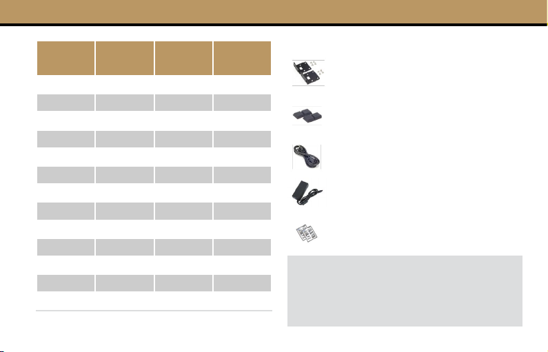
Part
Number
SC10010 24 Gigabit 2 SFP 400W
SC10020 24 100Mb 2 SFP 400W
SC10030 24 100Mb 2 Gigabit 250W
SC10040 24 Gigabit 2 SFP
SC10050 16 Gigabit 2 SFP 250W
SC10060 16 100Mb 2 Gigabit 250W
SC10070 16 Gigabit 2 SFP
SC10080 8 Gigabit 2 SFP 130W
SC10090 8 100Mb 1 100Mb 110W
SC10100 8 Gigabit
SC10110 4 Gigabit 1 Gigabit 65W
SC10120 8 SFP 2 Gigabit
SC10130 1 Gigabit 30W
Primary
Ports
Uplink PoE
Rack Mounting Kit - two brackets
and eight screws. (All models apart
from SC10090, SC10100 and SC10130)
Four adhesive foot pads (all models
apart from SC10130)
Power Cord (All models apart from
SC10090, SC10100, SC10110)
Power Adapter (SC10090,
SC10100, SC10110)
Documentation—Quick Start Guide
(this document) and Warranty Card
Note: The C-100 Series switches are for
indoor use only.
Note: Additional documentation can be
obtained from www.signamax.com
www.signamax.com2
Page 4
Mount the Switch
!
!
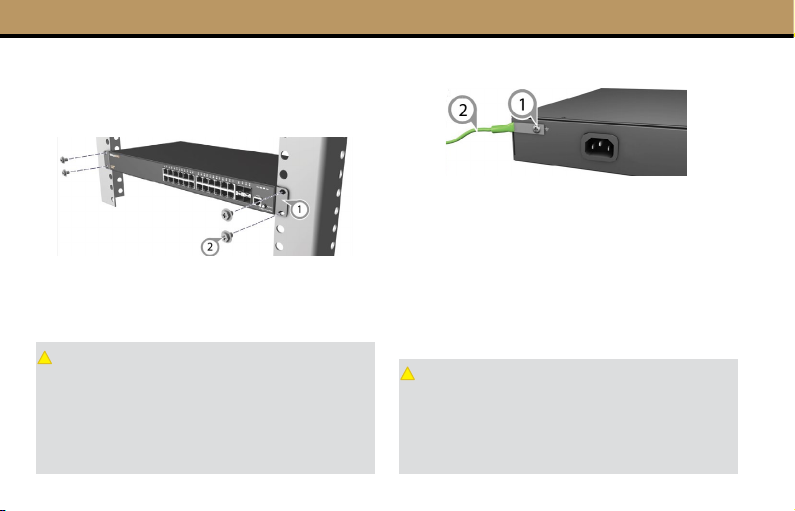
Mounting in a Rack
(All models apart from SC10090, SC10100 and SC10130)
1. Attach the brackets to the switch.
2. Use the screws and cage nuts supplied with the
rack to secure the switch in the rack.
Caution: Installing the switch in a rack requires
two people. One person should position the
switch in the rack, while the other secures it using
the rack screws.
Note: The switch can also be installed on a
desktop or shelf using the included adhesive
rubber foot pads.
Ground The Switch
1. Ensure the rack is properly grounded and in
compliance with ETSI ETS 300 253. Verify that there
is a good electrical connection to the grounding point
on the rack (no paint or isolating surface treatment).
2. Attach a lug (not provided) to a #12 AWG (PoE
switch) or #18 AWG (non-PoE switch) minimum
grounding wire (not provided), and connect it to
the grounding point on the switch rear panel. Then
connect the other end of the wire to rack ground.
Caution: The earth connection must not be
removed unless all supply connections have
been disconnected.
Note: The device must be installed in a restricted
access location. It should have a separate
protective earthing terminal on the chassis.
www.signamax.com3
Page 5
Connect Power
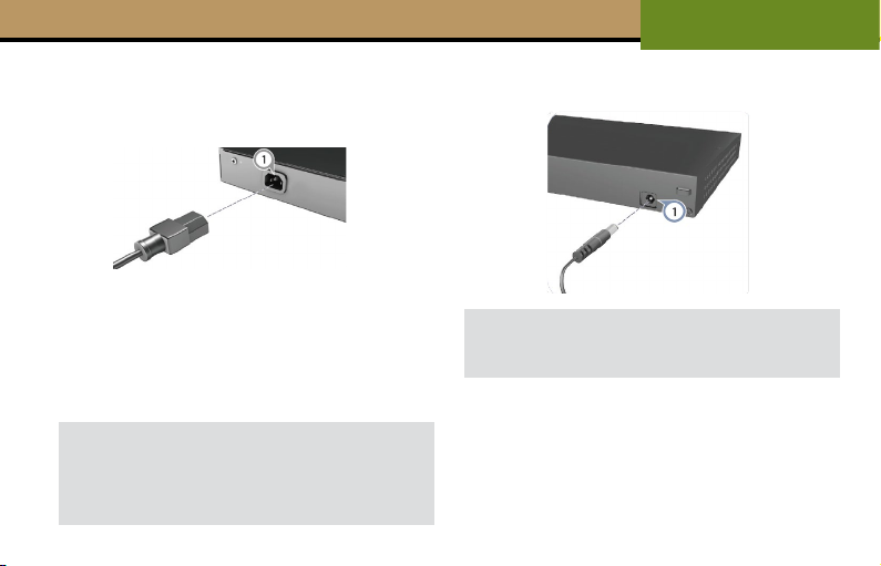
Connect AC Power
(All models apart from SC10090, SC10100 and SC10110)
1. Plug the AC power cord into the socket on the rear
of the switch.
2. Connect the other end of the power cord to an AC
power source. Verify that the external AC power
requirements for the switch can be met as listed: AC
100-240 V, 50-60 Hz.
Note: For International use, you may need to
change the AC line cord. You must use a line cord
set that has been approved for the socket type in
your country.
C-100 SERIES
QUICK START GUIDE
Connect DC Power
(SC10090, SC10100 and SC10110)
Note: The switches includes an AC/DC power
adapter. Connect the AC/DC power adapter to
the switch and to an AC power source.
1. Attach the brackets to the switch.
2. Use the screws and cage nuts supplied with the
rack to secure the switch in the rack.
4
www.signamax.com
Page 6
C-100 SERIES
QUICK START GUIDE
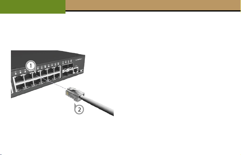
Connect Network Cables
www.signamax.com
1. For RJ-45ports, connect 100-ohm Category5, 5e or
better twisted-pair cable
2. For the SFP slots, rst install SFP transceivers and
then connect ber optic cabling to the transceiver
ports. The following transceivers are supported:
1000BASE-SX (065-79SXMG)
1000BASE-SX Extended Distance (065-79SXEDMG)
1000BASE-LX (065-79LXMG)
1000BASE-EX (065-79LXEDMG)
1000BASE-ZX (065-79ZXMG)
1000BASE-EZX (065-79EZXMG)
3. As connections are made, check the port status
LEDs to be sure the links are valid. See the LED
description table on the next page.
5
Page 7

LED Status Description
ON Internal power operating normally.
PWR
LINK
PoE
MODE
OFF
ON Port has a valid link
BLINKING Port has network activity
OFF The link is down
ON
BLINKING
OFF Doesn’t deliver PoE power
ON Port has a valid 1000 Mbps link
OFF Port has a valid 10/100 Mbps link
No AC power is connected or the
internal power supply has failed.
A PoE device is connected and
delivered PoE power
PoE Error: short circuit or current
overload
C-100 SERIES
QUICK START GUIDE
6
www.signamax.com
Page 8

CONNECT WITH US
999 NW 159th Dr, Miami, FL 33169
800.446.2377 / 305.944.7710
www.signamax.com
 Loading...