

SIGNAL-T ST 131 PIRANHA- II,ST 131N Technical Description And Operating Manual

TECHNICAL DESCRIPTION AND OPERATING MANUAL ST131 <PIRANHA II> and ST131N
1
ST 131 “PIRANHA- II”
ST 131N
MULTIFUNCTIONAL DETECTION DEVICES
TECHNICAL DESCRIPTION AND OPERATING
MANUAL

TECHNICAL DESCRIPTION AND OPERATING MANUAL ST131 <PIRANHA II> and ST131N
2
CONTENT
Introduction 3
1 General Characteristic 4
1.1 Purpose and main features 4
1.2 List of equipment 5
1.3 Description of the main components 6
1.4 Packaging 13
1.5 Detection channels 14
1.6 Power supply 15
2 Operation and display 16
2.1 Operation 16
2.2 Indication 17
2.3 Main menu 18
2.4 Information 19
3 Modes, sub-modes and options 20
3.1 "FULL RANGE" mode 20
3.2 "BAND" mode 22
3.3 "DEMODULATION" mode 23
3.4 "AUTOMATIC ANALYSIS" sub-mode 24
3.5 "MEMORY" sub-mode 27
3.6 "SCALE" sub-mode 29
3.7 "MEASUREMENTS" sub-mode 30
3.8 "OSCILLOSCOPE" option 31
3.9 “WATERFALL” option 33
3.10 "SPECTRAL SUBTRACTION" option 34
3.11 "DIGIT" option 36
3.12 "NON-LINEAR JUNCTION DETECTOR" option 38
4 Working with the ST131 40
4.1 Working with the "RADIO" channel 41
4.2 Working with the "WIRE" channel 52
4.3 Working with the "OPTICAL" channel 56
4.4 Working with the "ACOUSTO-ELECTRIC" channel 57
4.5 Working with the "NON-LINEAR JUNCTION DETECTOR" option 59
5 Main unit firmware update 60
6 Technical Specifications 61
7 Certificate of Acceptance 63
8 Warranty 64
ANNEX 1 66
ANNEX 2 67

TECHNICAL DESCRIPTION AND OPERATING MANUAL ST131 <PIRANHA II> and ST131N
3
INTRODUCTION
ST131 “PIRANHA II” is a multifunctional detection device intended for detecting and localization of
the special technical means (STM) for surreptitious information gathering.
ST131N - a multifunctional detection device that has all the features and functionality of ST131
«PIRANHA II» model with the additional option: NON-LINEAR JUNCTION DETECTOR in wired lines.
In the further, according to the text, unless otherwise specified, ST131 «PIRANHA II» and ST131N
models will be specified as ST131.
Prior to beginning of use of ST131, please read carefully this manual and keep it as a reference
book for further use.
Any part of information contained in this manual is subject to change without a notice.

TECHNICAL DESCRIPTION AND OPERATING MANUAL ST131 <PIRANHA II> and ST131N
4
1 GENERAL CHARACTERISTIC
1.1 Purpose and main features
A multifunctional detection device ST131 is intended for detecting and localization of special
technical means (STM) for surreptitious information gathering as well as identification of natural and
artificial sources of information leakage.
The main types of the STM, for detection of which ST131 is intended, are:
The STM with information transfer by radio channel. These primarily include:
• Radio microphones, including those with the accumulation and subsequent transfer of information (so-
called “burst transmitter” STM) and Frequency Hopping Spread Spectrum (FHSS);
Telephone radio transmitters;
Radio stethoscopes;
Video cameras with radio transmitters;
Unauthorized use cell phones and modems of CDMA, GSM, UMTS and DECT standards as well as the
devices with digital channels of data transmission such as WLAN, BLUETOOTH and LTE standards;
STM with the composition of the spatial high-frequency irradiation device;
Radio beacons for tracking of moving objects.
The STM that uses the following lines for information transfer: such as AC power,
telephone, coaxial, security and fire alarm cords.
The STM with information transfer in the infrared frequency range.
The STM with information transfer in the ultrasonic frequency range.
Natural and artificial channels of acoustic information leakage, detection of which is
included in the ST131 tasks, are:
Acoustic information channel emerged:
in wired lines for various purposes, as a result of acoustic-electric conversion ("microphone effect").
as a result of the absence or lack of sound insulation in the surveyed areas.

TECHNICAL DESCRIPTION AND OPERATING MANUAL ST131 <PIRANHA II> and ST131N
5
1.2 LIST OF EQUIPMENT
Basic set
1 Main unit.
2 “ST131.UHF” - UHF converter.
3 “ST131.AWL” – wire line adapter.
(“ST131.AWLN” for ST131N)
4 “ST131.UHF.A” - broadband UHF antenna.
5 Telescopic antenna.
6 «ST131.RAWL» - RF wire line adapter.
7 Probes set + alligator clips
8 220V clips (2 units)
9 "GROUND" wire
10 «F-BNC» adapter.
11 Power supply (2 units).
12 Main unit’s supporting device.
13 Main unit’s shoulder holder.
14 Tripod.
15 USB cable.
16 Hex-nut wrench.
17 AA-type batteries (8 pcs).
18 Headphones.
19 USB flash drive with software.
20 Technical description and operating manual.
Additional set
1 “ST131.SHF” - SHF antenna-detector
2 “ST131.IR” - infrared sensor
3 “ST131.TEST” - testing device
4 “ST131.MF” - Magnetic field sensor
5 “ST131.OV” - Bias voltage module
TECHNICAL DESCRIPTION AND OPERATING MANUAL ST131 <PIRANHA II> and ST131N
6
1.3 Description of the main components
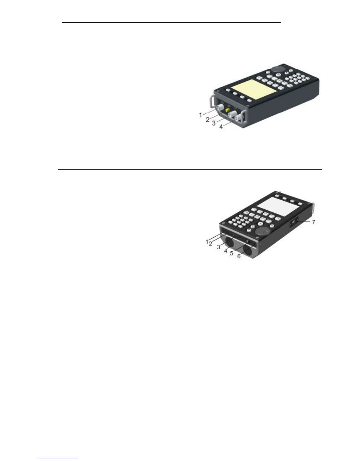
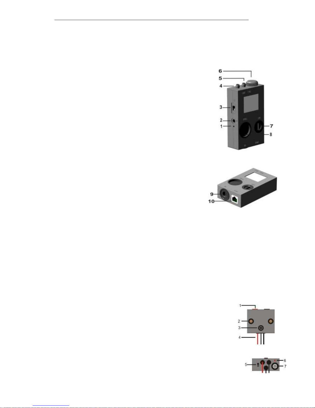
1.3.1 The main unit
Appointment of connectors and controls are shown
in Figures 1 and 2.
1 "I/O" Socket for connection of UHF converter
ST131.UHF, SHF-detector ST131.SHF, magnetic sensor
ST131.MF and infrared sensor ST 131.IR
2 "GEN" Test signal generator output (only for
ST131N)
3 "CH2" Socket for connection of probes
operating in the “ACOUSTO-ELECTRIC” channel and
magnetic sensor ST131.MF
4 "CH1" Socket for connection to the wire line adapter ST131.AWL and Telescopic antenna
1 Sound line out.
2 3.5’’ socket for headphones connection.
3 Volume knob.
4 Battery compartment covers.
5 ON/OFF switch.
6 Power supply socket.
7 USB slot.
On the bottom of the main unit comprises a screw-threaded hole for connecting the main unit
supporting block and shoulder holder, as well as labels with device number information and polarity
when inserting the batteries in the battery compartments.
Figure 1
Figure 2
Figure 1
TECHNICAL DESCRIPTION AND OPERATING MANUAL ST131 <PIRANHA II> and ST131N
7
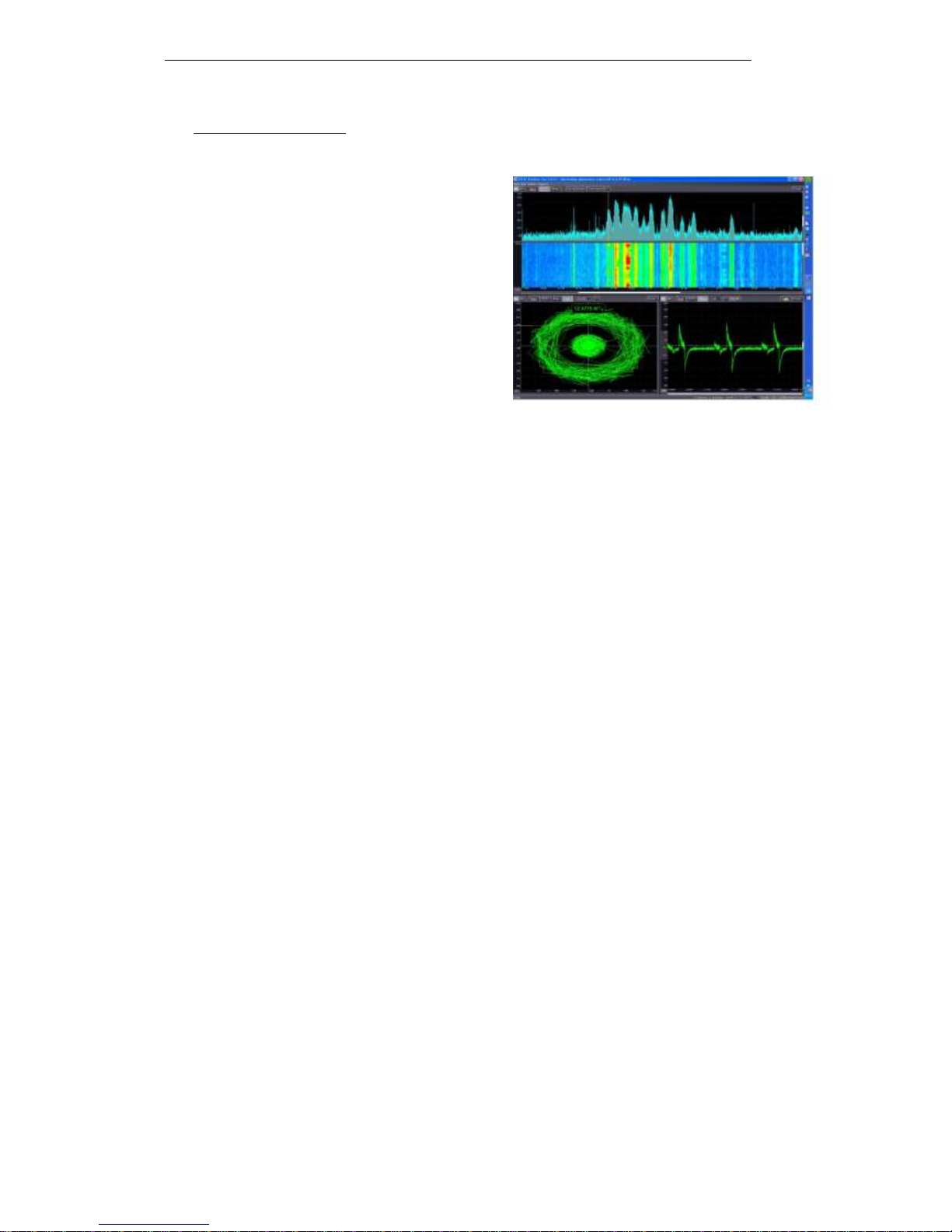
1.3.2 Software
ST131 ANALYZER PRO software enhance the ability and expands capacities of the device for
analyzing and processing of signals.
This software implemented the following:
Oscilloscope, spectral and vector analysis,
“waterfall”;
Creation of signals database;
MONITORING with expanded presets;
Stream recording of signals to HDD of PC;
Special detection algorithms.
PC transfer of data, that has been stored in
the ST131 main unit
Detailed information on the program and instructions for its use is on a USB-flash.
PC configuration required
CPU: 2 cores and 2 GHz or faster.
RAM: 1 GB at least.
Display: 1280 x 1024 resolution, widescreen recommended.
Ports: USB 2.0.
Operating system: Windows 8, 8.1, 7, Windows Vista, Windows XP.
TABLET configuration required
Operating system: Windows 8, 8.1 and above (full version).
Figure 3

TECHNICAL DESCRIPTION AND OPERATING MANUAL ST131 <PIRANHA II> and ST131N
8
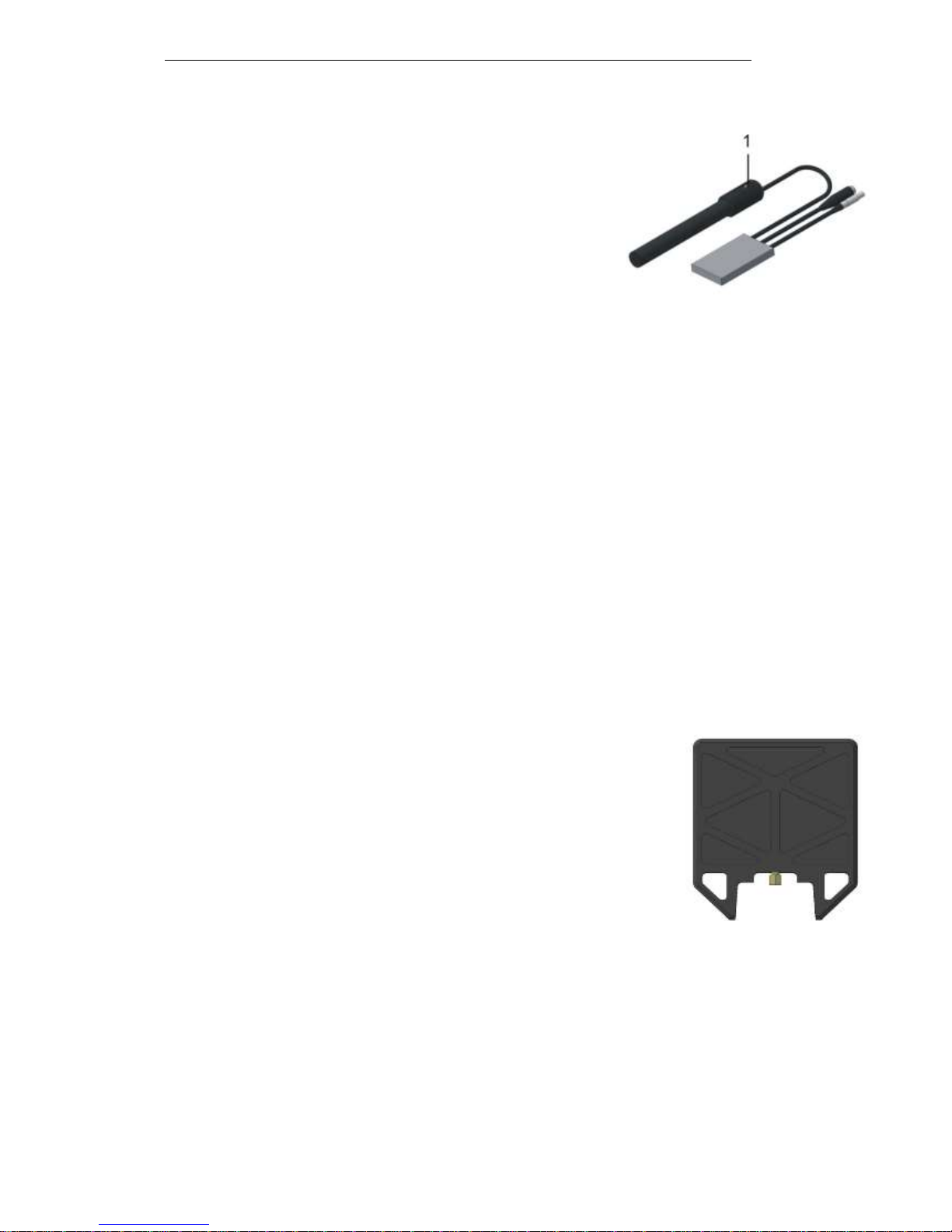
1.3.3 UHF converter "ST131.UHF"
ST131.UHF is connected to the "I/O" socket of the main unit.
1 SMA socket.
2 Switch-on and low battery power indicator.
3 ON/OFF switch.
4 Main unit link quality indicator.
5 Screw-threaded hole ¼”.
6 Battery compartment cover.
At the end part of the UHF converter handle there is a socket for power supply.
1.3.4 Wire lines adapter «ST131.AWL»/ «ST131.AWLN»
ST131.AWL/ ST131.AWLN is a monoblock in which structurally united:
Step-down transformer voltage converter assigned to operate in the frequency range from 0.01
to 30 MHz;
• Low frequency differential amplifier assigned for operation in the acoustic frequency range (0.3-
15 KHz).
Switching device controlled directly from the main unit and provides connection to the contact
pairs of the RJ-45. Connection can be to the most common combinations of pairs as well as
user-defined pair.
Amplifier for test signal generator (only for ST131N).
1 Sockets for probe connection.
2 "GROUND" contact.
3 RJ-45 sockets.
4 “LINE” voltage indicator.
5 “PWR/LINK” power and main unit data exchange
indicator.
6 "OVERLOAD" indicator of input signals.
At the bottom of the adapter there are elements of attachment to supporting device and a
shoulder holder to the main unit.
ST131.AWL connects to the main unit’s corresponding sockets.
Figure 4
Figure 5
1
2
3
4
5
6
TECHNICAL DESCRIPTION AND OPERATING MANUAL ST131 <PIRANHA II> and ST131N
9
The “WIRE 0.01-30 MHz” channel is designed for the analysis of signals in the 0.01-30 MHz
frequency band and the “WIRE 0.3-15 KHz” channel is for the 0.3-15 KHz frequency band.
Connecting to the explored line executes through connectors:
• RJ-45 (3), that provides a pass-through connection to the ETHERNET and phone line.
• Sockets for probe connection (1), which provide a connection to other types of conductive lines with
using of additional clips, if necessary.
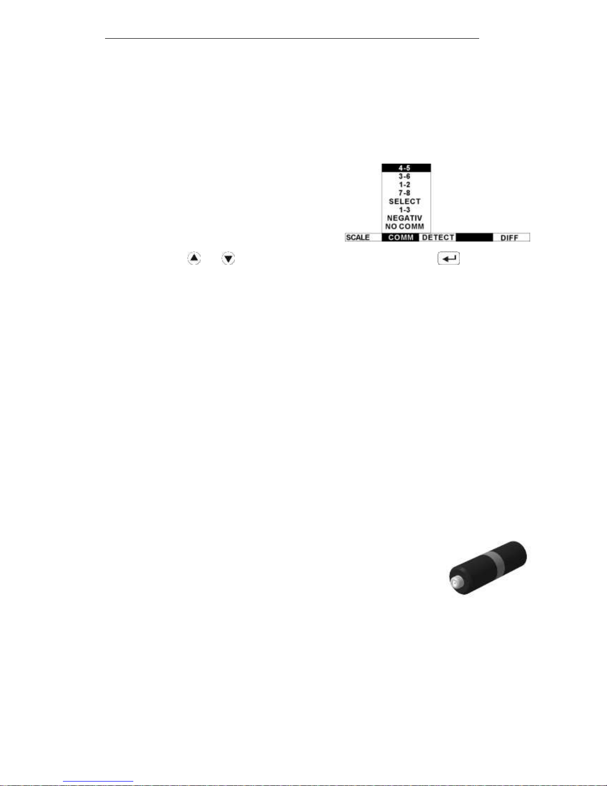
Pressing the “COMM” button of the main unit
provides a choice for switching pairs of wires connected
to the RJ-45:
Combination "4-5", "3-6", "1-2" and "7-8" are
the most likely options of pairs.
Use the button and to select the choice and confirm by pressing the or rotary knob.
"SELECT" – sets the user-defined pair (except of the same name to avoid short-circuit):
• 1st pin number (1-8): Entering the first contact from the numeric keypad.
• 2nd pin number (1-8): Entering the second contact.
The specified pair is indicated in position 10 of Fig 18.
"NEGATIV"/ "POSITIV" – changes the polarity of the pair of wires.
"NO COMM" - disconnection from the explored line.
ST131.AWL remains operable under voltage at input connectors no more than 380V.
Attention! When working with ST131.AWL, in order to avoid electric shock,
obey the rules of electrical safety.
1.3.5 RF wire line adapter «ST131.RAWL».
ST131.RAWL is designed to work in the "WIRE 30-3000 MHz” channel.
ST131.RAWL is a single monoblock with integrated circuit protection
against high voltage up to 250V.
ST131.RAWL is connected to the same type SMA connector like the
ST131.UHF converter. Input connector "F" type is designed for direct
connection to the coaxial line. Use «BNC-F» adapter to connect to the line with
BNC connector.
.
Figure 6
TECHNICAL DESCRIPTION AND OPERATING MANUAL ST131 <PIRANHA II> and ST131N
10
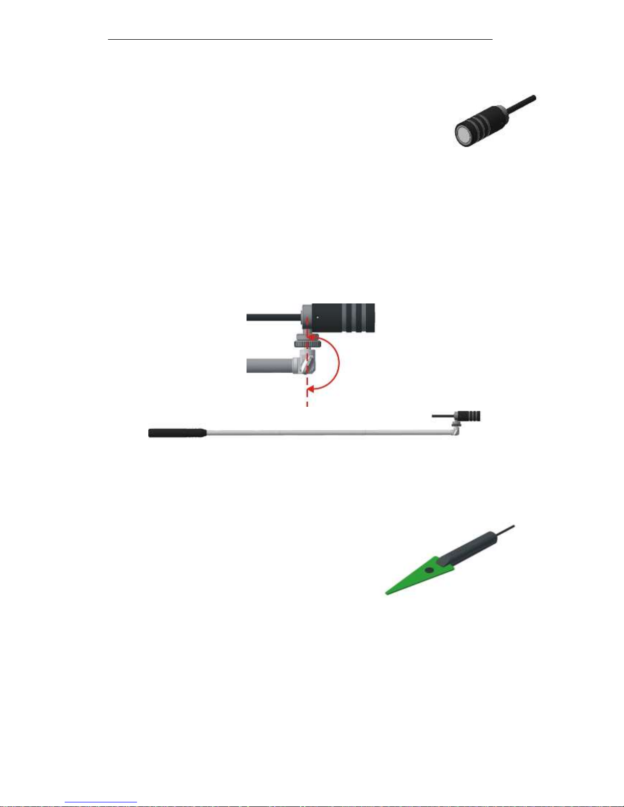
1.3.6 Infrared sensor "ST131.IR"
This sensor structurally consists of receiving photodiode and pre-amplifier.
This sensor is connected to I/O socket of the main unit.
The front side of sensor has the screw-thread used for connection of the
special monopod.
1.3.6.1 Monopod
The monopod is intended for facilitation of search of IR transmitting devices which installed at
external side of the window aperture in the direction “from the window”.
The monopod structure consists of four sections with total length of 900 mm. A turning mechanism
provides efficient setting of necessary viewing angle within the range up to 180o.
1.3.7 SHF antenna-detector "ST131.SHF"
ST131.SHF consists of the structurally integrated log-
periodic antenna and SHF detector-amplifier.
The handle comprises a screw-threaded hole 1/4" for
connection to the tripod.
It is connected to I/O socket of the main unit.
Figure 9
Figure 7
Figure 8
TECHNICAL DESCRIPTION AND OPERATING MANUAL ST131 <PIRANHA II> and ST131N
11
1.3.8 Magnetic field sensor ST131.MF.
St131.MF consists of a ferrite antenna and pre-amplifier.
1 The mode selector"GRAD-MAG"
__________________________________________________________________________
The Thread hole ¼” is on the opposite side of the ferrite antenna.
ST131.MF operates in two modes:
«MAGNETOMETER"- directly as a magnetic field intensity sensor (a mode selector is in a position
"MAG").
"GRADIOMETER" - as a gradiometer (a mode selector is in position "GRAD").
In this mode an influence of remote strong sources of magnetic field is reduced
significantly as well as influence of other disturbing impacts (acoustic, vibro-acoustic, etc).
ST131.MF connected to the sockets «I/O» and «CH2» of the main unit.
1.3.9 UHF antenna "ST131.UHF.A"
ST131.UHF.A is a passive broadband antenna.
It is connected to the input SMA socket of the ST131.UHF converter
(position 1, Figure 4).
Figure 11
Figure 10
TECHNICAL DESCRIPTION AND OPERATING MANUAL ST131 <PIRANHA II> and ST131N
12
1.3.10 Testing device "ST131.TEST"
The "ST131.TEST" is intended to control operability of devices ST131 and ST131N by testing all
detection channels in the main unit as well as rest equipment (sensors, antennas, adapters, converters).
The "ST131.TEST" has six control signal sources corresponding to the ST131 detection channels
as well as non-linear element to check the non-linear junction detector.
1 Battery charge indicator.
2 Power supply socket "5V".
3 ON/OFF switch.
4 Connector "CH2" - output of signals to check the "ACOUSTO-
ELECTRIC" channel.
5 Connector "UHF" - output of signals to check the "RADIO 30-
4400 MHz" channel.
6 Rotary knob.
7 Reception cavity “SHF” for the ST131.SHF detector.
8 Reception cavity "MAG" for the ST131.MF magnetic field
sensor.
9 Reception cavity “IR” for the ST131.IR infra-red sensor.
10 Socket "AWL" - output of signals to check the "WIRE"
channel.
Complete information about working with ST131.TEST is in the "Technical description and user
manual ST131.TEST".
1.3.11 Bias voltage module«ST131.OV»
«ST131.OV» for the bias (supply) voltage wire line with a view to enhancing connected to this line
eavesdropping devices
1 Contact sockets for connecting to the line
2 Contact sockets for connecting the voltmeter
3 Setting bias voltage
4 Wires for connection to ST131AWL
5 polarity switch
6 Power supply connection indicator
7 Connector for power supply
Figure 12
TECHNICAL DESCRIPTION AND OPERATING MANUAL ST131 <PIRANHA II> and ST131N
13
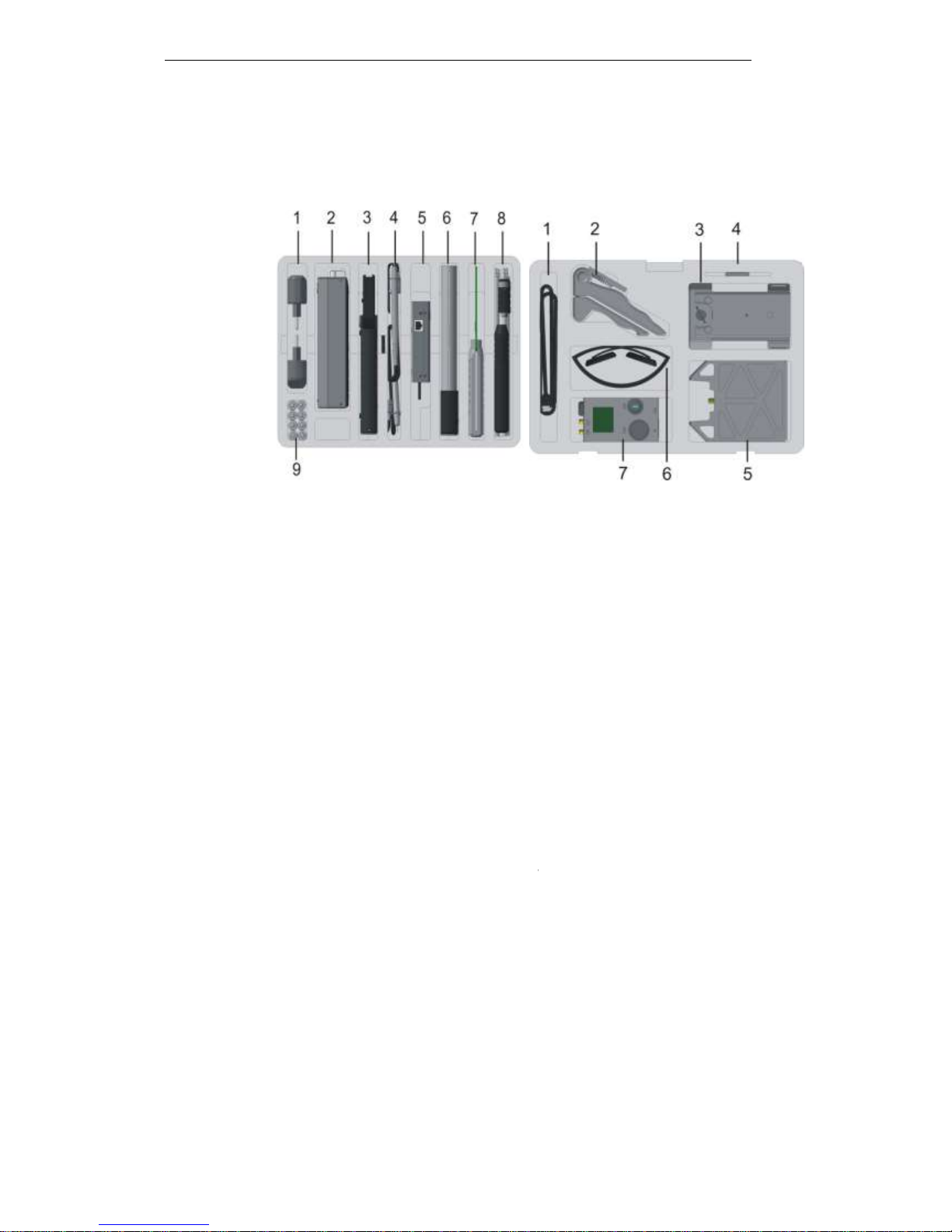
1.4 PACKAGING
The ST131 device is packed in a special shock-proof and water-resistant black color case with
dimensions 400 x 304 x 165 mm.
Special location foam polyurethane plates are installed in the case body for convenient and reliable
placement of all components of the device. Arrangement of the components is shown in Figure 13.
1 Power supply (2 units).
2 Main unit.
3 UHF converter ST131.UHF.
4 Probes set + alligator clips +
220V clips + "GROUND" wire.
5 Wire line adapter ST131.AWL/ST131.AWLN.
6 Magnetic field sensor ST131.MF.
7 UHF antenna-detector ST131.SHF.
8 Infrared sensor ST131.IR + monopod
9 AA-type batteries (8 pcs) + hex-nut wrench.
________________________________________________________________
1 USB cable.
2 Tripod.
3 Shoulder mount and main unit’s supporting
device.
4 USB flash drive.
5 UHF antenna ST131.UHF.A + wire line
adapter ST131.RAWL + "F-BNC" adapter +
telescopic antenna.
6 Headphones.
7 ST131.TEST testing device with accessories.
Figure 13
TECHNICAL DESCRIPTION AND OPERATING MANUAL ST131 <PIRANHA II> and ST131N
14
1.5 DETECTION CHANNELS
ST131 has four detection channels.
Detection channel
Frequency range
RADIO
0.01-30 MHz
30–4400 MHz
4–18 GHz
WIRE
0.3-15 KHz
0.01–30 MHz
30–3000 MHz
OPTICAL
770-1650 nm (0.001-30 MHz)
ACOUSTO-ELECTRIC
0.01–125 KHz
List of channels access is provided by pushing " " button and selecting "SELECT CHANNEL"
in the "MENU".
1.5.1 «RADIO» CHANNELS
Selective receiving and subsequent processing of radio signals within the range of
0.01 – 18000 MHz is provided in this channel.
To work in a range of 0.01-30 MHz, the telescopic antenna or other antenna of this frequency
range can be used.
To work in a range of 30-4400 MHz, the ST131.UHF converter and the ST131.UHF.A antenna are
used.
For operation in the 4-18 GHz microwave detector «ST131.SHF» is used.
1.5.2 «WIRE» CHANNELS
This channel provides receiving and subsequent processing of the signals transferred by wire line
of different purpose (power networks, telephone networks, computer networks, security and fire alarm
lines, etc.). These lines can be de-energized as well as alive ones (AC or DC voltage) up to 250V.
Use the ST131.AWL wire line adapter to work in a range of 0.3-15 KHz and 0.01-30 MHz.
Use the ST131.RAWL RF adapter and the ST131.UHF converter together to work in a range of 303000 MHz.
1.5.3 «OPTICAL» CHANNEL
Receiving and subsequent processing of the radiations in the optical frequency range is provided in
this channel.
The ST131.IR infrared sensor is used together with a special monopod to work in this channel.
1.5.4 «ACOUSTO-ELECTRIC» CHANNEL
Receiving, amplifying and analyzing of signals within the frequency range of 10 Hz – 125 KHz is
provided in this channel.
Ultrasonic signal is converted into audio frequency signal by means of frequency transfer.
Application of different types of acoustic transducers depends on the tasks considering parameters
of this channel.

TECHNICAL DESCRIPTION AND OPERATING MANUAL ST131 <PIRANHA II> and ST131N
15
1.6 POWER SUPPLY
1.6.1 Main unit
Power supply of the ST131 main unit is provided by means of six AA-type batteries (or rechargeable
batteries) or power adapter.
Completely filled icon (position 11, Figure 14) corresponds to full capacity of the battery,
completely discolored and strikethrough image corresponds completely discharged batteries.
It is preferable to use heavy-duty alkaline batteries.
Under average operating condition (backlight is switched on for 50% of time, volume level – 50%
of maximum level) hours of service of one set of batteries is not less than 5 hours at least.
It is possible to use only one battery compartment (three batteries). In this case the service time is
reduced to 1 hour.
To replace the batteries, please open the battery compartment covers with the wrench included
into delivery set. Replace the batteries observing polarity given at the bottom cover of the main unit.
1.6.2 UHF converter ST131.UHF
UHF converter is powered by two AA type batteries (or rechargeable batteries) or power adapter.
When the batteries are discharged the continuous lighting of the indicator «ON/LOW BAT» (position
3, Figure 4) will be replaced by blinking one time per second.
Service life of the device when using evidently new batteries of alkaline type should be at least two
hours.
To replace the batteries, please open the battery compartment covers and replace the batteries
observing polarity indicated at the bottom part of the battery compartment.

TECHNICAL DESCRIPTION AND OPERATING MANUAL ST131 <PIRANHA II> and ST131N
16
2 OPERATION AND DISPLAY OF ST131
2.1 OPERATION
CONTEXT BUTTONS (4)
Definition of the context buttons – depends on the selected detection channel, operating
mode in this channel is indicated in the lower line of the display.
When pushing or rotary knob changes the buttons context: basic or supplementary.
FUNCTIONAL BUTTONS (5)
- switching on the FULL RANGE mode
- switching on the BAND mode
- switching on the DEMODULATION mode
- switching on the SCALE sub-mode
- access to measuring functions
SUPPLEMENTARY BUTTONS
and are intended for sequential switching between the bands in the BAND
mode, choice of the displayed part of the "RADIO 30-4400 MHz" range: "30-4100 MHz" or "300-4400
MHz" and changing the display brightness (using the ) (1)
– entry in the main MENU (2)
– entry in the indication of current settings (3)
– switching in the MEMORY sub-mode (6)
- switching in the AUTOMATIC ANALYSIS sub-mode (7)
and - choice in MENU and pop-up lists and set the displayed maximum signal level (8)
- zero in the numeric keypad and automatic adjustment of the current spectrogram or oscillogram
in vertical screen size (9)
– confirmation of selection (aka ENTER) (10)
– decimal point and reset of the accumulation results of detectors (11)
– - digital keyboard (12)
Figure 14

TECHNICAL DESCRIPTION AND OPERATING MANUAL ST131 <PIRANHA II> and ST131N
17
“ON/OFF switch” (position 5, Figure 2) is designed to switch on/off the ST131 main unit.
“Volume control” (position 3, Figure 2) regulates the output audio level of the built-in loudspeaker
or headphones. Adjustment is possible if it is provided for a particular mode (an icon of volume control
accessibility is indicated in position 12, Figure 15). Numerical value of the volume level (0-99) is displayed
in position 11.
Use automatic adjustment of the current spectrogram and oscillogram in vertical screen
size by pressing the button.
Manually moving the horizontal axis of the spectrogram is made by and . One press
changes the displayed boundaries of levels by 5 dB in position 6, figure 14. So you can make vertical
shift of the spectrogram to view it more comfortable. If you work with the oscillogram, these buttons
increase or decrease the displayed amplitude of the signal.
Reset of the averaged results of the detectors is carried out by pushing the button.
2.2 INDICATION
The common way of signal indication in the ST131 are spectrograms. Common elements are
shown in Figure 15.
1 Start and end of the displayed frequency range.
2 Short name of the current channel.
3 Mode.
4 Sub-mode.
5 Overload Indicator / The maximum possible level of
signal that displayed without overload. *
6 The lower and upper level of the displayed signal
(dynamic range).
7 Frequency and maximum level of signal considering the spectral resolution. **
8 Noise level.
9 Gain value of the input amplifier of the main unit.
10 Attenuator value of the ST131.UHF converter (“RADIO 30-4400 MHz" and “WIRE 30-3000 MHz"
channels) or the number of the selected RJ-45 connector pair ("WIRE 0.01–30 MHz” and “WIRE 0.3-15
KHz" channels).
11 Battery level indicator.
12 Volume level indicator.
13 Mute or sound control availability indicator.
* The maximum possible signal level without overload is implemented only for the "RADIO 30-4400
MHz" and "WIRE 30-3000 MHz" channels.
**For example, spectral resolution in the FULL RANGE mode of the "RADIO 30-4400 MHz" channel
is 32 MHz. Indication of 930 MHz frequency means that the maximum signal is within the range of
930+/-16 MHz. Thus the accuracy of measuring frequency is +/- 16 MHz.
Figure 15
TECHNICAL DESCRIPTION AND OPERATING MANUAL ST131 <PIRANHA II> and ST131N
18
2.2.1 OVERLOAD INDICATION
The appearance of the inscription "OVERLOAD" (position 5, Figure 14) means that at the entrance to
the main unit there is the signal exceeding the allowable maximum input signal at that setting.
In the "RADIO 30-4400 MHz" channel with the factory setting, this message can be caused by the 10
mW signal power at a distance of about one meter, or one watt at a distance of about ten meters.
Moment of appearance of this inscription set in the MENU (section 2.3). By default, this indication
appears only for the long-term overload. You can change that setting by pressing the button,
selecting "ADVANCED SETTINGS" and checking "More indicat. of overloading." After that it will be
displayed by any, even the short-term overload.
To avoid the overload, do the following:
change your location or turn off the source of this signal, if possible.
successively decrease the amplifier gain input value ( ) and then pressing until
the overload is removed from display.
In the "RADIO 30-4400 MHz" channel to avoid the overload use the attenuator located in the UHF
converter. Once pressing the button leads to automatically calculated level from 5 to 30 dB in
steps of 5 dB to eliminate overload (with indication in position 10, Figure 15). Manually, the necessary
attenuation of the input signal can be selected from the list after clicking on .
If the attenuator value is 30 dB, overload in "RADIO 30-4400 MHz" channel will be triggered by the 1 W
signal at 1 meter.
It should be noted that the source of overload may be signals that are beyond the investigated
band (“BAND” mode) but still in the frequency range of this channel (“FULL RANGE” mode). This can
lead to the "OVERLOAD" indication although the signal is not seen on the spectrogram.
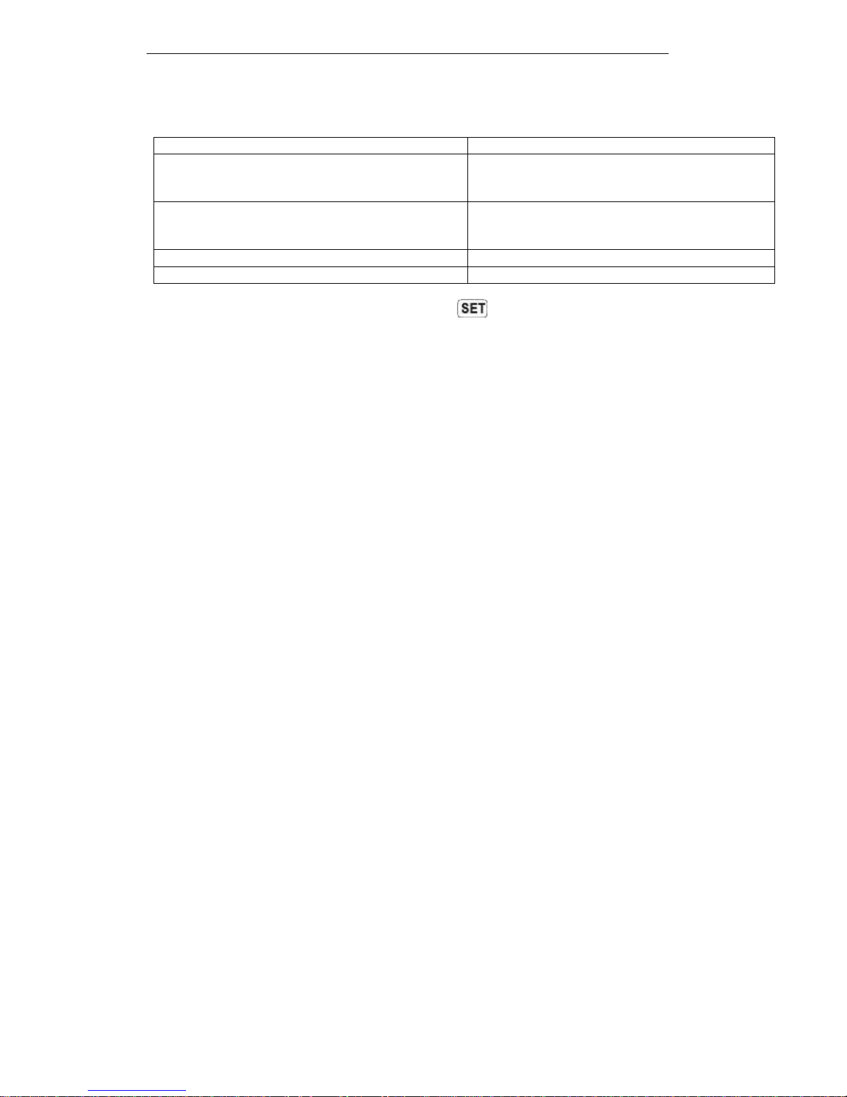
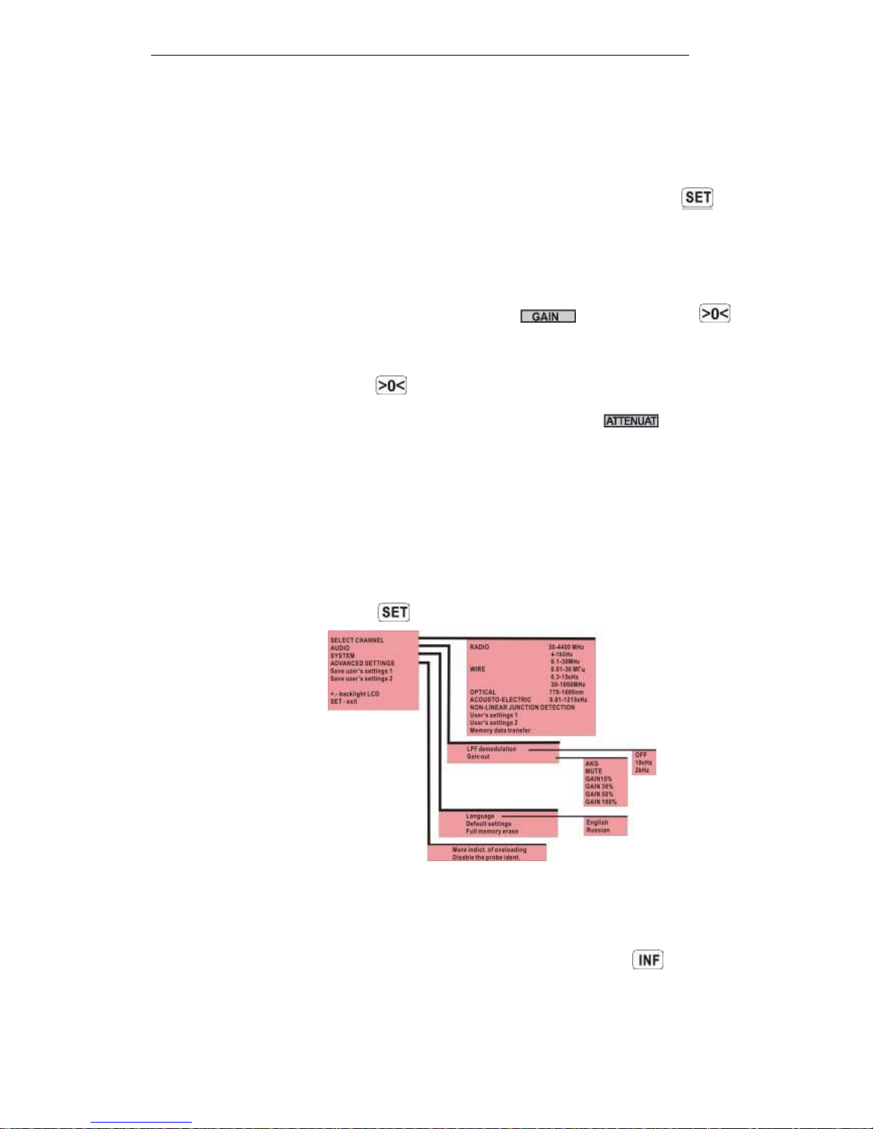
2.3 MAIN MENU
To enter main MENU press the button.
"Memory data transfer…" – turns on the main unit into the two-way data transfer. See “ST131
Analyzer Pro. User’s Manual" to get description of that process.
"Save user’s settings..." – saves the current settings (preview by clicking ). To restore the
saved settings, select "User's settings..." in the start menu.
“LPF demodulation” – selection of cutoff frequency of the 1st order low-pass filter at the output
of the demodulator.
Figure 16
TECHNICAL DESCRIPTION AND OPERATING MANUAL ST131 <PIRANHA II> and ST131N
19
"Gain out" – selects level of signal for line and headphones output in the DEMODULATION mode.
It defaults to automatic gain control ("AGC"). No use in the “WIRE 0.3-15 KHz” and “ACOUSTOELECTRIC” channels.
"Full memory erase" - complete data erasure held in non-volatile memory of the main unit.
"More indicat. of overloading" – selecting of this setting provides instant indication of overload
at the time of its occurrence in position 5, Figure 15. five-second delay as a default. Short-term overload
indication is usually caused by band and out of band transients.
This option also includes an additional indication if the displayed signal beyond the screen but no
overloading (the message "OVERSCL.").
"Disable the probe ident."- disable the identification and diagnosis of external converters such
as ST131.UHF и ST131AWL.
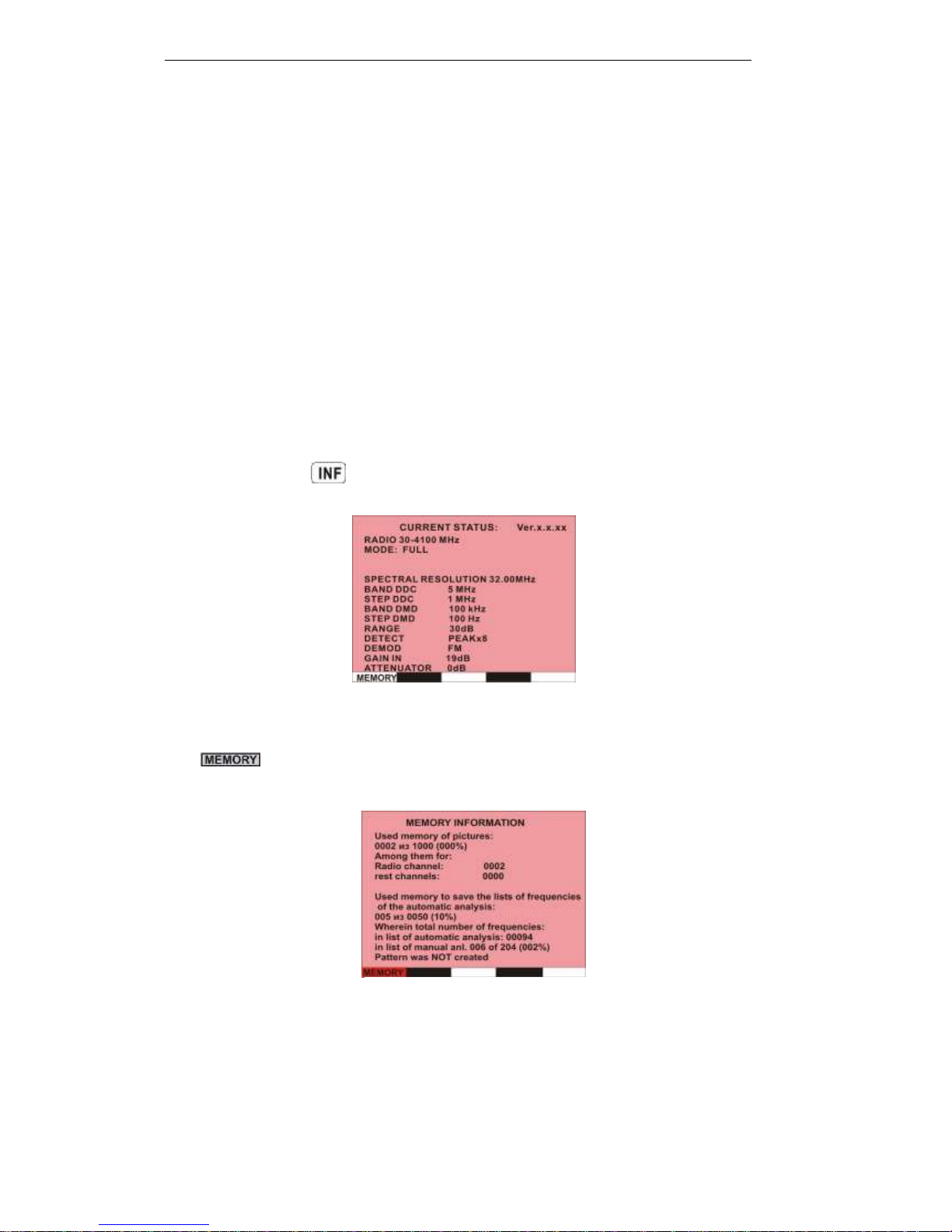
2.4 INFORMATION
With pressing the button information about current settings of the device appears.
“Ver.x.x.xx”- current number of device’s firmware version.
" " - access to the information window of distribution of device’s non-volatile memory. If
selected, it is highlighted in red.
Figure 17
Figure. 18
TECHNICAL DESCRIPTION AND OPERATING MANUAL ST131 <PIRANHA II> and ST131N
20
3 MODES, SUB-MODES AND OPTIONS
following features have been realized in ST131:
THREE MODES: “FULL RANGE”, “BAND” and “DEMODULATION”.
FOUR SUB-MODES: “SCALE”, “AUTOMATIC ANALYSIS”, “MEMORY” and
“MEASUREMENTS”.
FOUR OPTIONS: “OSCILLOSCOPE”, “SPECTRAL SUBTRACTION”, “DIGIT” and “NON-
LINEAR JUNCTION DETECTOR” (only for ST131N).
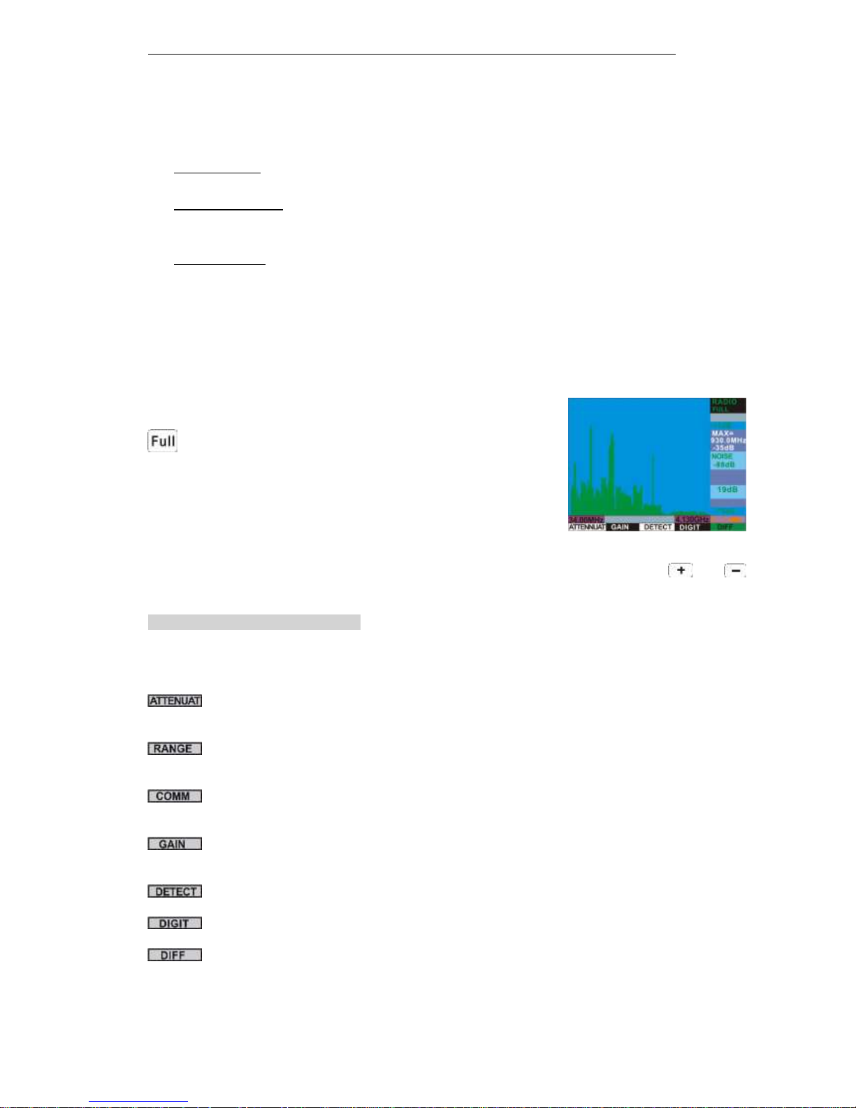
3.1 “FULL RANGE” MODE
In general, this mode is intended for visual estimation of the signal occupancy in the full frequency
range and quick detection the signals with relatively strong level.
Entry in this mode is carried out automatically after selection of
the channel from the list of the channels in start MENU or by pressing
(except “RADIO 4–18 GHz” channel).
The large frequency range of the "RADIO 30-4400 MHz” channel is divided into two sub-ranges:
“30-4100 MHz” and “300-4400 MHz”. Switching between sub-ranges is performed by and
buttons.
CONTEXT BUTTONS FUNCTIONS______________________________________________
All possible main and auxiliary context buttons in this mode for all channels are presented below.
Definition of the buttons can be different in each channel.
- selects the attenuator level (0-30 dB) of the ST131.UHF converter in the "RADIO 30-4400
MHz” channel. It is displayed on position 1, Figure 15.
- selects the displayed dynamic range of signal levels (30, 60 or 120 dB). It is displayed on
position 6, Figure 15.
- selects the pair of RJ-45 connector in the "WIRE" channels (see section 1.3.4). It is displayed
on position 1, Figure 15.
- selects the gain of the input amplifier for the main unit as well as automatic gain control
(AUTO).
- selects signal averaging (see section Annex 1).
- access to the "DIGIT" option in the "RADIO 30-4400 MHz" channel (see section 3.10) .
- access to the “SPECTRAL SUBTRACTION” option (see section 3.9) and the detailed pattern
(see section 3.4.1).
_______________________________________________________________________
TECHNICAL DESCRIPTION AND OPERATING MANUAL ST131 <PIRANHA II> and ST131N
21
When you click on the rotary knob or button, a number of auxiliary context
buttons appears.
FUNCTIONS OF THE AUXILIARY CONTEXT BUTTONS_______________________________
- access to context-sensitive help (under construction).
, - selects analyzing frequency bandwidth. Function is active in the BAND mode. All
possible bandwidth values depend on the selected channel.
- activates the 'PULSE' option.
______________________________________________________________________
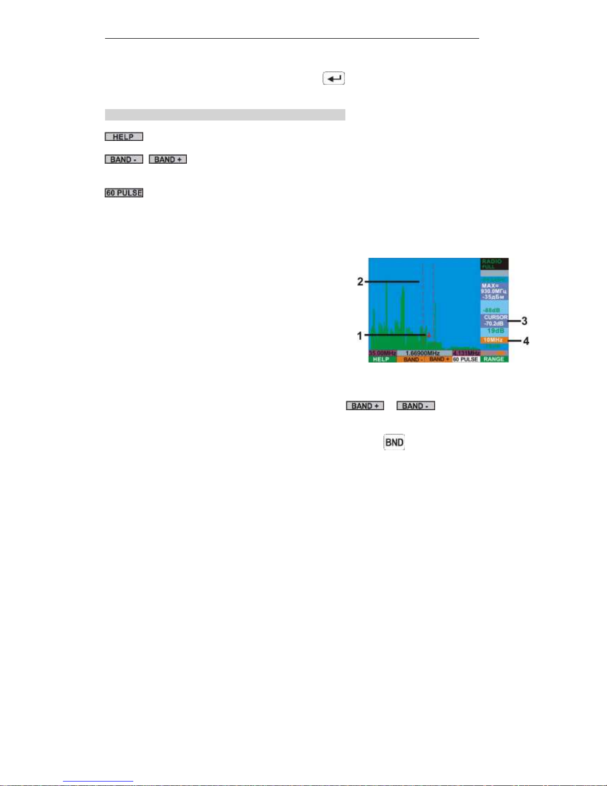
For detailed analysis (the "BAND" mode), gently turn the rotary knob. The cursor lines and
new context buttons will appear on the screen (Figure 19).
1. Marker of the tuned frequency.
2. Cursor lines of the frequency band for the BAND
mode.
3. Signal level value corresponding to the position of
the marker.
4. Bandwidth value for the BAND mode.
Selection of the cursor lines location on the spectrogram performed by rotating the rotary knob.
Changing the frequency bandwidth is achieved by pressing or . The distance between
cursor lines will be changed proportionally, if possible.
Lists of bandwidth and their particular features are different depend on the selected channel.
After selecting the center frequency and bandwidth, press the button to switch to the BAND
mode. Selected band will be shown on the full screen.
Figure 19
 Loading...