

Signal Dynamics Switch Cubes, LINX User Manual

1
Contents
Introduction Page 2
Instrumentation Page 7
Operation / Function Page 9
Programming Page 18
Appendix Page 21
All Rights Reserved. Reproduction by any means, electronic or mechanical
including photocopying, recording or by any information storage and retrieval
system or translation in whole or in part is not permitted without written
authorization from Signal Dynamics Corporation.
Copyright © Signal Dynamics Corporation.
Installation Page 3
Wire Diagram Page 22
Warranty Page 24

2
LINX™ Network Bus Electrical System
System Overview:
Simpler, easier installation and comprehensive rider information; these
are the some of the basic advantages of the LINX™ Network Bus
Wiring System. As you read this manual you will realize the significant
improvements and advanced features that this system provides over
conventional wiring harnesses. Additionally, updates, knowledge base
and Q&A for this system will be updated and posted on the LINX™
web-site as they occur at www.SignalDynamics.com/LINX.
How does LINX™ work?
LINX™ is a serial data communication network for connecting the
various electrical functions of the motorcycle over a single network
cable, eliminating complex electrical wiring, confusion and errors while
wiring or troubleshooting the electrical system.
LINX™ System
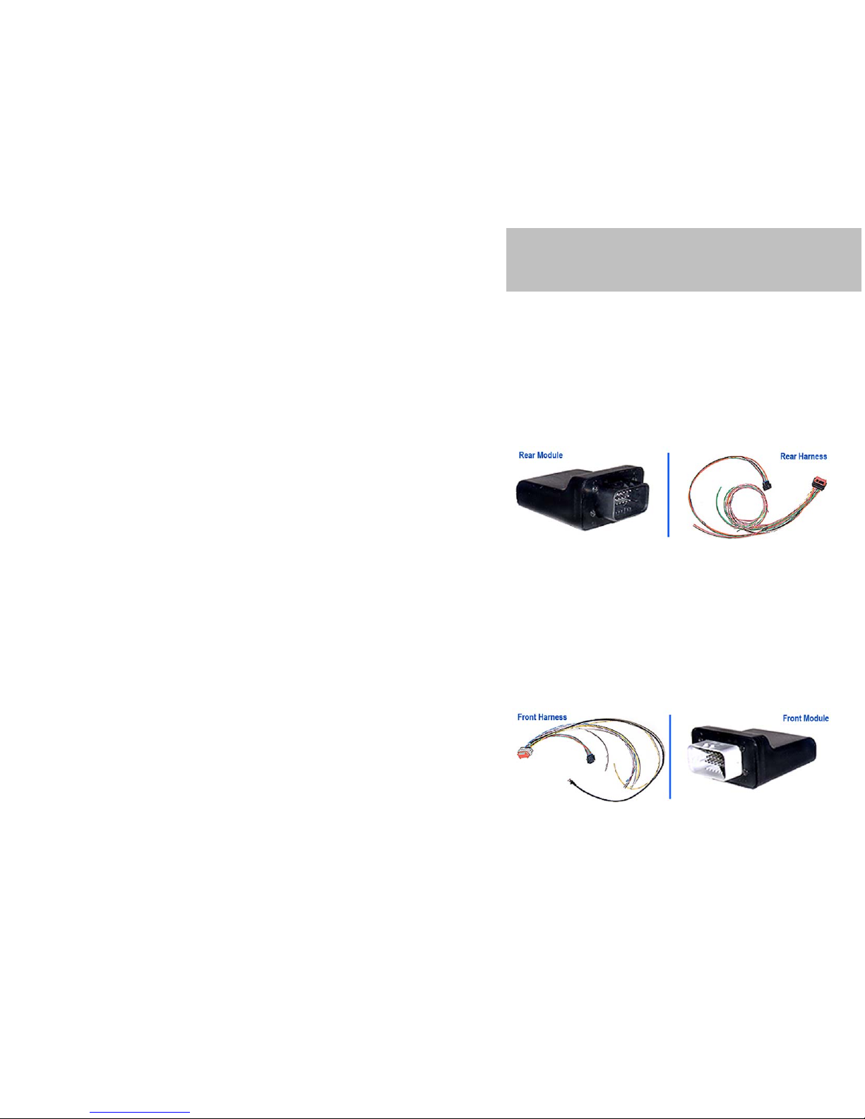
The LINX™ system is composed of: three communication modules, two
handle bar switches, and two wiring harnesses. These modules when
connected with the network cables, communicate with each other,
transfer information and self-check themselves for proper operation. If a
problem does develop, a written text message is displayed on the Liquid
Crystal Display (LCD) module. The system is designed to be simple, yet
provide more practical and useful information to the user.
Introduction
3
Locating Rear Module
The rear module is identified by its’ Black Connector, and should be
located in an area that is close to the battery and Starter Solenoid, and
also central to all of the devices it connects to. The module is splash
proof, but should be mounted in an area that has some protection from
water and heat. Under the seat on the battery box is usually a good
location. The module mounts with the enclosed double sided tape.
Locating Front Module
The front module is identified by it’s Grey Connector, and should be
located in an area that is central to all of the devices it connects to.
Under the gas tank, or in the headlight housing are two common
locations. The module is splash proof, but should be mounted in an area
that has some protection from water and heat. Once the two modules are
mounted the 4 wires that connect them should be connected. A 4 pin
connector is included, but these wires can be cut or extended as needed.
The module mounts with the enclosed double sided tape.
Installation
4
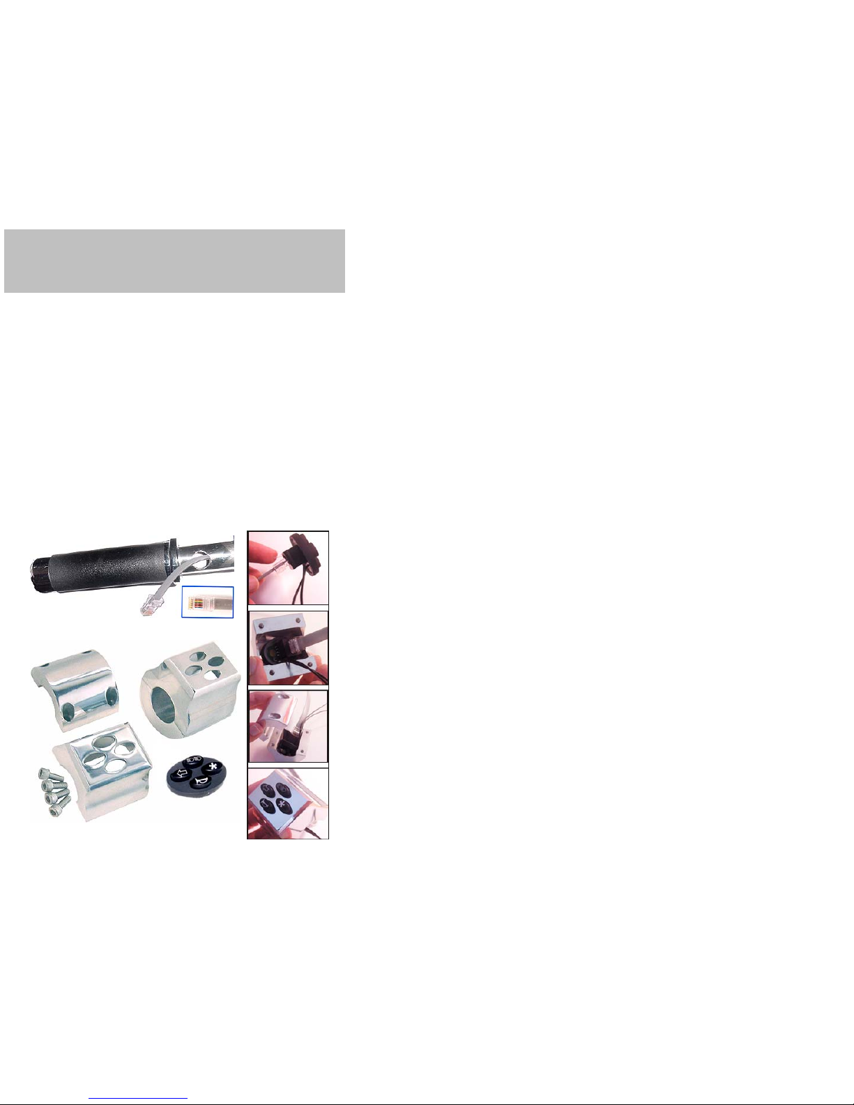
Installing switch cubes
The switch cubes are designed to fit a 1” handlebar, and connect to the
front brake switch, and clutch switch (optional). Installing the switch
cubes involves drilling a hole in the handlebar where the switch cube
will be located, and another where the wires will connect to the display
module. These wires come with the ends already crimped on, but they
can be cut off and easily re-crimped in the event you need to fish the
wire through a small hole (see crimping instructions). After the hole is
drilled and the wire fished through, simply plug the connector into the
switch, and connect the two wires on the right side to the brake switch,
and the two wires on the left side to the clutch (optional). It is
recommended that an electrical grease (not included) be used on the
connector and socket to help prevent corrosion from moisture. Last
insert the switch into the housing, and install the four screws through the
back side of the saddle clamp.
Installation

5
Installing the Display Module
The display module can be mounted either above or below the handlebar
by attaching the backing plate mounting tab to a handlebar clamp (not
included). The wires from the switch cubes will come out of the
handlebars, into the display housing, and plug into the appropriate
connector. The data wire from the front module is routed to the display
module and plugged into the appropriate connector. The data wire comes
with the end already crimped on, but it can be cut off and easily recrimped in the event you need to fish the wire through a small hole, or
shorten it (see crimping instructions). It is recommended that electrical
grease (not included) be used on the data cable and socket to help
prevent corrosion from moisture. Be sure to plug the cables into the
correct sockets as the unit can be damaged from improper installation.
They are labeled “L” & “R” (for Left & Right handlebar switches) and
“C” for Front Module.
Installation
6
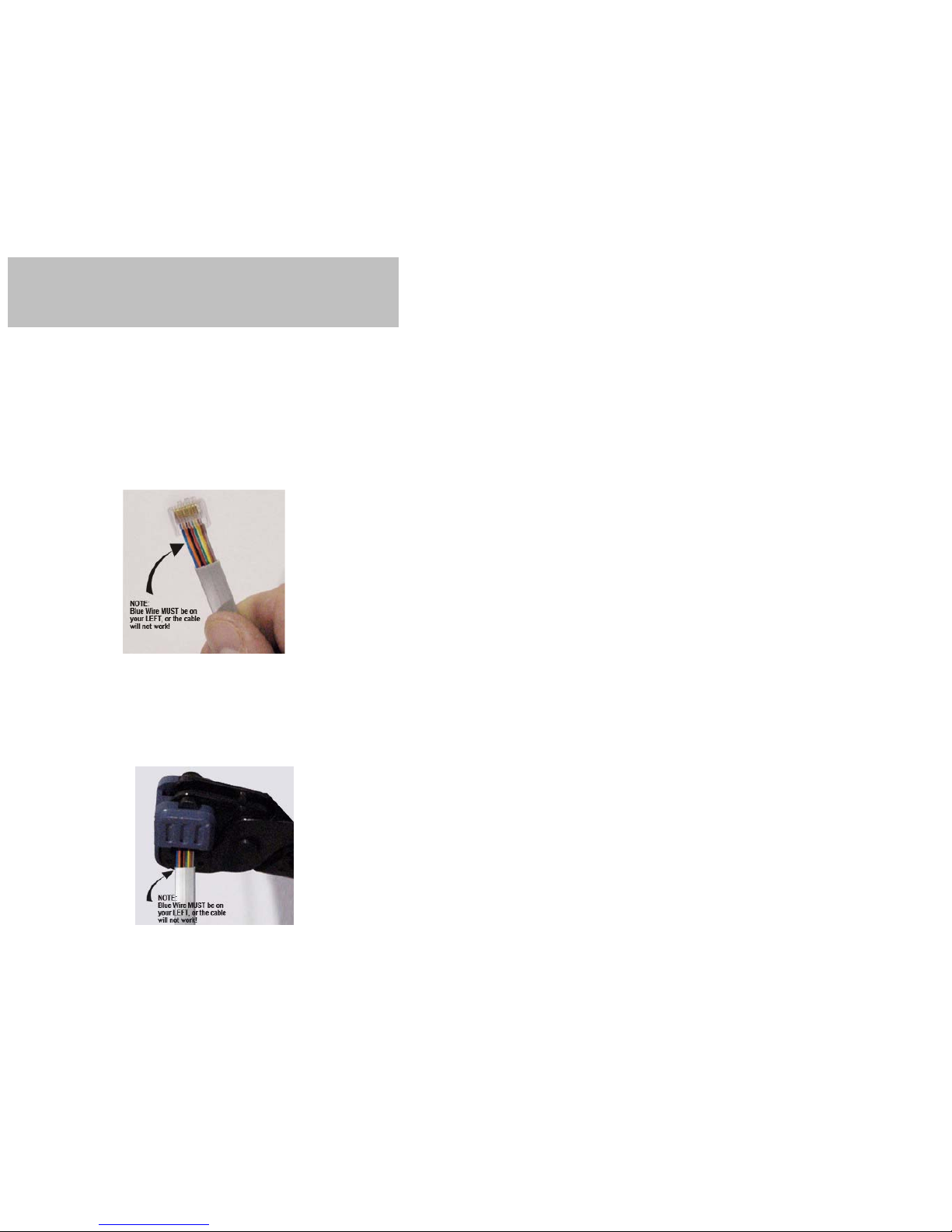
To Replace the Connector End on a Cable.
1. Strip about 1” of the outer insulation with an RJ-45
stripper/crimping tool, the inner insulation does not need to be
stripped. These tools are commonly used to crimp computer
network cables, and are avalible at most electronic stores.
2. Insert the wires into the low profile connector. Be sure the blue wire
is to your left with the clip of the connector away from you, and the
connector pointing up.
3. Insert the connector into the crimper, and crimp. Be careful no to
push the connector too far into the crimper as the low profile
connectors do not have a stop to position the connector at the
correct position. Also be sure the wires are all of the way into the
connector when you make the crimp. It is a good idea to crimp the
connector twice to be sure that all of the conductor pins have
pierced the wires.
Installation
7
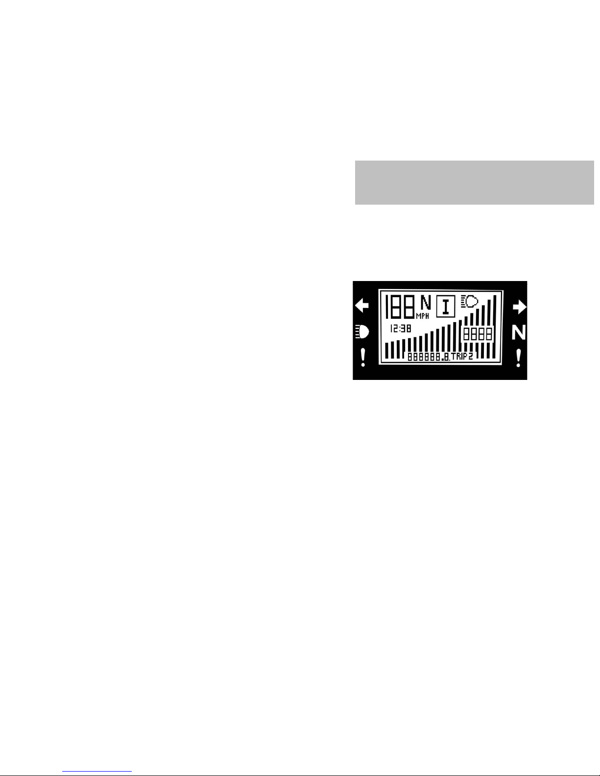
Display Module:
When the system is powered-on, a self-test will run and if any faults are
noted, they will be displayed. After this, the logo will be displayed for 3
seconds, and then the module will enter the operational mode. The
following items will be displayed on the screen in the operational mode:
Information & Icons on LCD Screens:
• Speed (in MPH or KPH).
• Engine RPM (digital readout and bar graph).
• Clock.
• High Beam “ON” Icon.
• Bike in “Neutral” Icon.
• Information Window (one of the following)
• Turn Signal Left / Right
• Hazard Flasher On.
• Run / Kill Status.
• Text information window: (toggles between the following with the
# key on the right handlebar switch).
• Odometer
• Trip 1 (Reset by pressing the # key for 3 seconds)
• Trip 2 (Reset by pressing the # key for 3 seconds)
Instrumentation
 Loading...