

Page 1
INTRODUCTION
Sailplanes are an easy and relaxing way to learn and enjoy radio control flying. To fly them well, however, takes a lot of skill
and knowledge about the air in which they fly. The RISER was designed with the beginner and sport flier in mind to create a
The versatile RISER can even make a good R/C trainer! Many model clubs around the country like to train student pilots on
a sailplane because of their gentle and slow speed flying characteristics. The slow speed allows the beginner ample time to
task soaring events. Since they aren't necessary for everyday fun flying,
the materials for adding spoilers to your RISER are not included in the kit.
Notes Before Beginning Construction
Any references to right or left refers to your right or left as if you were seated in the cockpit.
To build good flying models, you need a good straight building board. Crooked models don't fly well! The building board can
as long as it is perfectly flat and untwisted.
prevent gluing the parts to the plans.
"floater" that's docile and predictable in flight. The RISER'S gentle handling characteristics doesn't mean it lacks
performance. Experts will find the RISER is capable of holding its own in two-meter sailplane competition.
develop the skills that are necessary for flying radio controlled models. If you have never flown an R/C model before, we
strongly recommend that you obtain the assistance of a skilled R/C pilot before attempting to fly your Riser for the first time.
Instructions for installing the optional wing spoilers are included with the kit on a separate sheet. Spoilers are essential for
making consistent spot landings and for other multi-
be a table, a workbench, a reject "door core" from the lumber yard, or whatever Cover the top surface of the building board with a piece of celotex-type wall board or foam board, into which pins can be
easily pushed. Don't hesitate to use plenty of pins during assembly to hold drying parts in correct position.
When pinning and gluing parts directly over the full-size plans, cover the plan with wax paper or plastic kitchen wrap to
Page 2
.
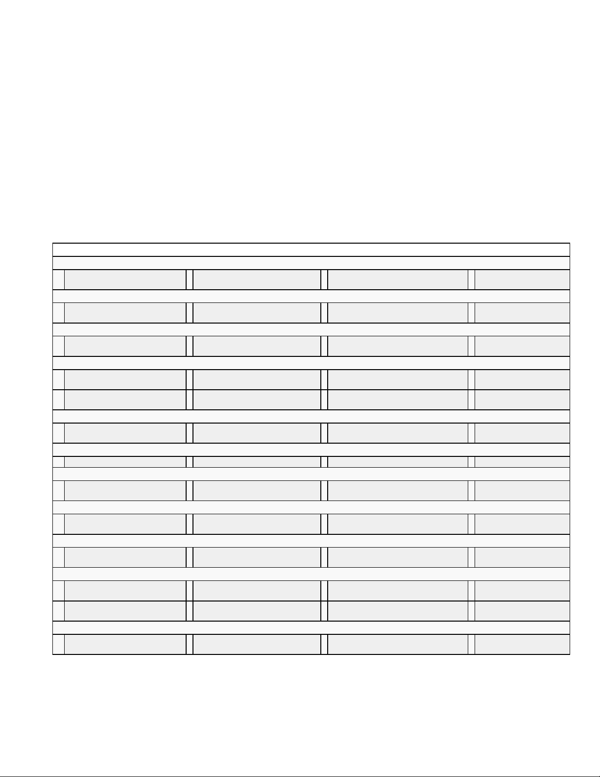
All of the other parts can be identified by the "COMPLETE KIT PARTS LIST". Sort the different sizes of sticks and sheets
into individual piles to avoid confusion during building. Cut all long pieces of balsa first, followed by medium lengths, before
construction.
1/4"x8" Fuselage
1/8"x3/16"x36" Diagonal Ribs for
About The Building Sequence
same assembly at the same time, such as the front and rear sections of the fuselage.
Don't use a ball point pen for making marks on the model during construction. If not sanded off, these ink marks will show
through the model's final finish. Use a pencil instead of a pen.
Identifying Kit Parts
Leave all die-cut parts in the sheets until needed in construction. Then remove the pieces from the sheets carefully. If
difficulty is encountered, do not force the part from the sheet - use a modeling knife to cut it free.
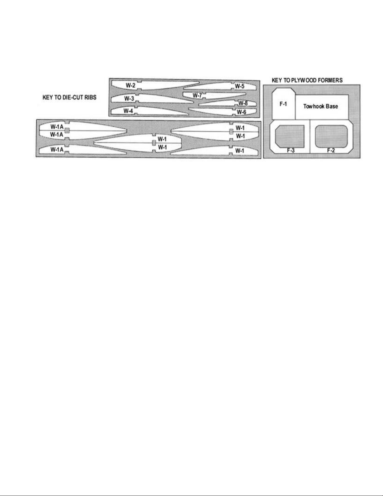
The die-cut balsa wing ribs are identified below. The die-cut plywood parts can be identified using the plans and the "KEY
TO PLYWOOD FORMERS". Mark the identification numbers on the corresponding parts before removing them from the
die-cut sheets.
cutting up any full length strips into short pieces.
NOTE: Save any scrap balsa and plywood until the model is completely done. Some of it may be called for during
COMPLETE KIT PARTS LIST
Die-Cut Balsa
2 1/16"x3"x18" Inboard Wing
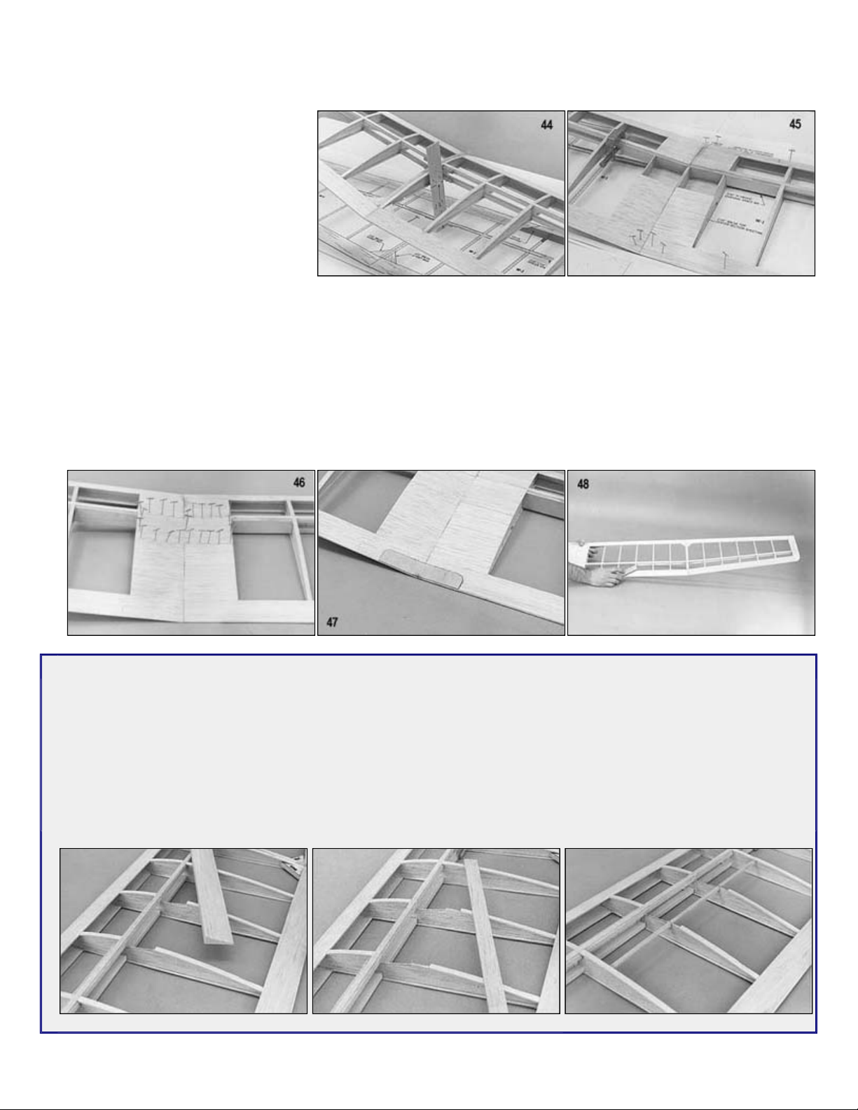
Panel Ribs, W-1 & W-1A
Silkscreened Balsa
1 3/32"x5"x36" SHEET NO.1;
Fuselage Sides
Sheet Balsa
8 1/16"x1"x20" Leading Edge
Sheeting
Stick Balsa
14 1/16"x3/16"x36" Capstrips 3
3 1/4" Triangle x36" Fuselage
Longerons
Special Shaped Balsa
4 1/4"x1"x20" Trailing Edge
Stock
Block Balsa
2 3/4"x1"x 6" Wingtips 1 1-1/2"x2"x2-1/2"; Nose Block
Hardwood
1 1/4"x3/4"x1" Basswood -
Notched Towhook Block
Spruce
4 1/8"x1/4"x18" Outboard Wing
Spars, Top and Bottom
Die-Cut Plywood
2 1/32"x4-1/2"x9-1/2" Fuselage
Doublers FDF, FDR
Hardware
6 Easy Hinges 2 Small Molded Nylon Control
4 2-56 x10" Threaded Rods 2 .190" o.d.x20" Outer Nylon
Miscellaneous Parts
1 3/32" dia.x1-7/8" Formed Wire
Towhook
2 1/16"x3"x12" Outboard Wing
Panel Ribs, W-2 thru W-8
1 3/16"x3"x18" SHEET NO.2; Tail
Parts
1 1/16"x3"x36" Wing Center
Sheeting, Shear Webs
Tail, Fuselage Stiffeners
4 3/8"x20" Shaped Leading Edge
2 5/32" dia. x3" Birch Dowels -
Wing Hold-down Dowels
4 3/16"x1/4"x 20" Inboard Wing
Spars, Top and Bottom
1 3/32"x2-3/8"x11" Dihedral Brace 1 1/8"x4-1/2"x6" Fuselage Formers,
Horns (for elevator and rudder)
Pushrod Tubing
1 38"x50" Full-Size Printed Plan 1 28 Page Instruction Booklet 1 3"x4-1/2" Decal
1 3/32"x3"x36" Fuselage Sheeting,
Top and Bottom
3 3/16"x1/4"x36" Stabilizer, Elevator,
Fin and Rudder Frames
1 3/16" sq. x4" Elevator Joiner
Towhook Base
5 #2 x1/2" Sheet Metal Screws (for
control horns & hatch hold-down)
2 .130" o.d.x24" Inner Nylon Pushrod
Tubing
1 1/4"x2-
Top Block and Hatch
1 1/4" Triangle x12"
Fuselage Longerons
2 2-56 R/C Links
(clevises)
The quickest and most efficient way to complete a model is to work on several pieces at the same time. While the glue is
drying on one section, you can start on or proceed with another part. Work can even go forward on several sections of the
Page 3
.
Radio Equipment Requirements
model to interference from model car or boat drivers (who may not even be in sight), it is also against the law.
Glues
Thin CA has a watery consistency and uses capillary action to penetrate and soak into a joint. Since it is so thin and
BOND is handy for gluing things such as wing leading edge sheeting or center sheeting where you need to apply glue
Keep in mind that the numbering sequence used in these instructions was chosen as the best way to explain the building
of each major component and is not intended to be followed in exact one-two-three fashion. Start on the wing at NO.1 and
after doing as many steps as is convenient, flip over to "FUSELAGE CONSTRUCTION" and do a step or two there, then
over to "TAIL SURFACECONSTRUCTION" and so forth. You will, of course, arrive at points where you can go no farther
until another component is available. Plan ahead! Read the instructions completely and study the full size plans before
beginning construction.
The RISER requires only elevator and rudder control, so any radio with two or more channels may be used. If you plan to
use spoilers, a radio with at least three channels is required. Be certain that your radio system's frequency is approved for
use in R/C model aircraft. Using a frequency assigned to R/C surface vehicles (cars, boats) not only endangers your
There are so many different glues available today for model construction that it can be confusing even for the experienced
modeler. To simplify matters, most glues can be classified as one of four basic types:
1. Fast cyanoacrylate adhesives (abbreviated in these instructions as "CA") such as SIG CA, Hot Stuff, Jet, etc ...
2. Easy-to-use water-based glues such as SIG-BOND (yellow) and SIG SUPER-WELD (white).
3. Super strong (but heavier) two-part epoxy glues such as SIG KWIK-SET (5-minute cure) and SIG EPOXY (3-hour
cure).
4. Traditional solvent-based model cements such as SIG-MENT.
Each of these types has different characteristics and advantages. Often times, the choice of which type to use is strictly a
matter of personal preference based on your prior experience with a previous model. Some of the steps in these
instructions call out the type of glue to use for that particular assembly. In other areas you can use your own judgement as
to which type is best suited to the purpose and to your building schedule.
For general construction of the RISER, we recommend that you use cyanoacrylate adhesives. These adhesives have
become very popular with modelers because of their fast drying times. With CA, you can virtually build a structure from
start to finish without having to wait for the glue to dry. Most brands, including SIG CA, come in three different viscosities:
thin, medium, and thick.
dries so quickly, the parts to be joined must be in firm contact with each other before application of the glue. Use
thin CA for the initial assembly of balsa parts over the plans.
Medium viscosity CA (SIG CA PLUS) can also be used for initial assembly in the same manner as the thin, but it
takes a little longer to dry. Joints made initially with thin CA should be reglued with medium CA for additional
strength. Medium CA should also be used when gluing plywood, spruce, or hardwoods.
Thick CA (SIG CA SLOW) dries slowly enough that it allows you to apply the glue to the parts before assembling
and gives you time to reposition the parts if necessary. Thick CA is good for gluing doublers to fuselages and
forming fillets in high stress areas.
The drying time for all CA's can be speeded up by spraying an accelerator (such as SIG KWIK-SHOT) right on the joint.
SIGto several parts in one operation. You should also have on hand some epoxy glue, both 5-minute and slow dry, for areas
subject to high stress or joints involving metal parts.
Page 4
.
You can't get along without a good sanding block
working in tight places and for careful shaping where a big block is too hard to control.
WING CONSTRUCTION
Inboard Wing
Cut pieces of 1/16"x3/16" balsa for the bottom rib cap strips.
the spruce spar in relation to the trailing edge.
planking, spruce spar, and trailing edge stock.
patterns to a piece of scrap plywood. Cut
and pin the rib in place.
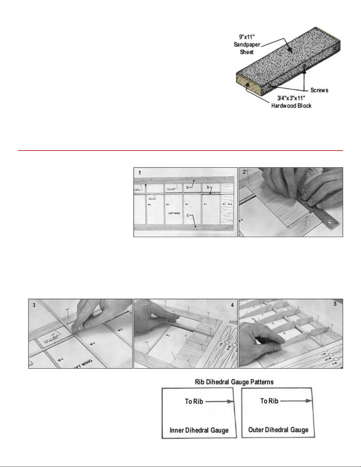
An assortment of different size sanding blocks are indispensable tools for
model construction. A good general purpose block can be made by wrapping
a 9"x11" sheet of sandpaper around a piece of hardwood or plywood. Use
three screws along one edge to hold the overlapped ends of the sandpaper.
Put 80-grit paper on the block during general construction. Switch to 220-grit
paper for final finish sanding just before covering.
Another handy block can be made by gluing sandpaper onto a 24" or 36"
long piece of aluminum channel stock. Most hardware stores carry a rack of
aluminum in various sizes and shapes. This long block is very useful for
sanding leading and trailing edges accurately.
Finally, glue sandpaper onto different sizes of scrap plywood sticks and round hardwood dowels. These are handy for
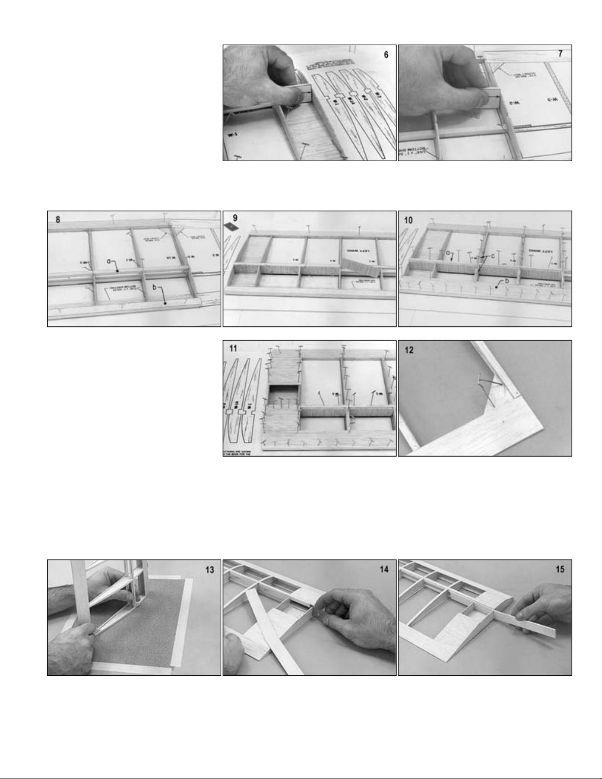
1.
a. Pin down the 1/16"x1" front
bottom sheeting.
b. Pin down the 1/16"x3/16" balsa
spar cap strip.
c. Pin down the 1/4"x1" trailing
edge.
2. Cut pieces of 1/16"x3" balsa for the
center section sheeting. Glue and pin in
place.
3.
4.
Glue and pin the rib cap strips in place. Add the 3/16"x1/4" spruce spar on top of the spar cap strip. Use a few ribs to locate
5.
Glue and pin all ribs in place except for the two end ribs located at the dihedral joints. Glue the ribs to the cap strips,
6.
Glue the inboard and outboard guide
out the patterns and use the inboard rib
guide to angle W-1A panel end rib. Glue
7.
Use the outboard rib guide to angle W1A outer rib. Glue and pin the rib in
place. Use scrap 1/16" balsa to level the
guide.
Page 5
.
c.
Glue and pin the 1/16"x3/16" rib cap strips.
where the 3/32" plywood dihedral brace
Repeat this procedure for the other inboard wing panel so that you will have one left panel and one right panel.
8. a. Glue and pin the 3/16"x1/4" top
spruce spar in place.
b. Glue and pin the shaped leading
edge in place.
9. Cut vertical grain pieces of 1/16"x3"
balsa sheet for spar shear webs. Glue
and pin these in place. Note that these
extend oniy out to the fourth rib bay.
10.
a. Glue and pin the top spar cap strip.
b. Glue and pin the 1/16"x1" top sheeting.
11. Cut pieces of 1/16"x3" balsa sheet for
the top center section sheeting. Leave
open, as shown in the picture, the area
WR will be installed.
12. Cut the wing gussets from the 3/16"
printed balsa sheet. Glue wing gusset
WGR in place as indicated on the plan.
13. Tape a piece of 80 grit sandpaper to a flat surface. Carefully sand the inboard and outboard dihedral joints.
14. Complete cutting the slots in the two balsa ribs for dihedral brace WR as shown in the picture.
15. Trial fit dihedral brace WR buf do not glue in place at this time.
Page 6
.
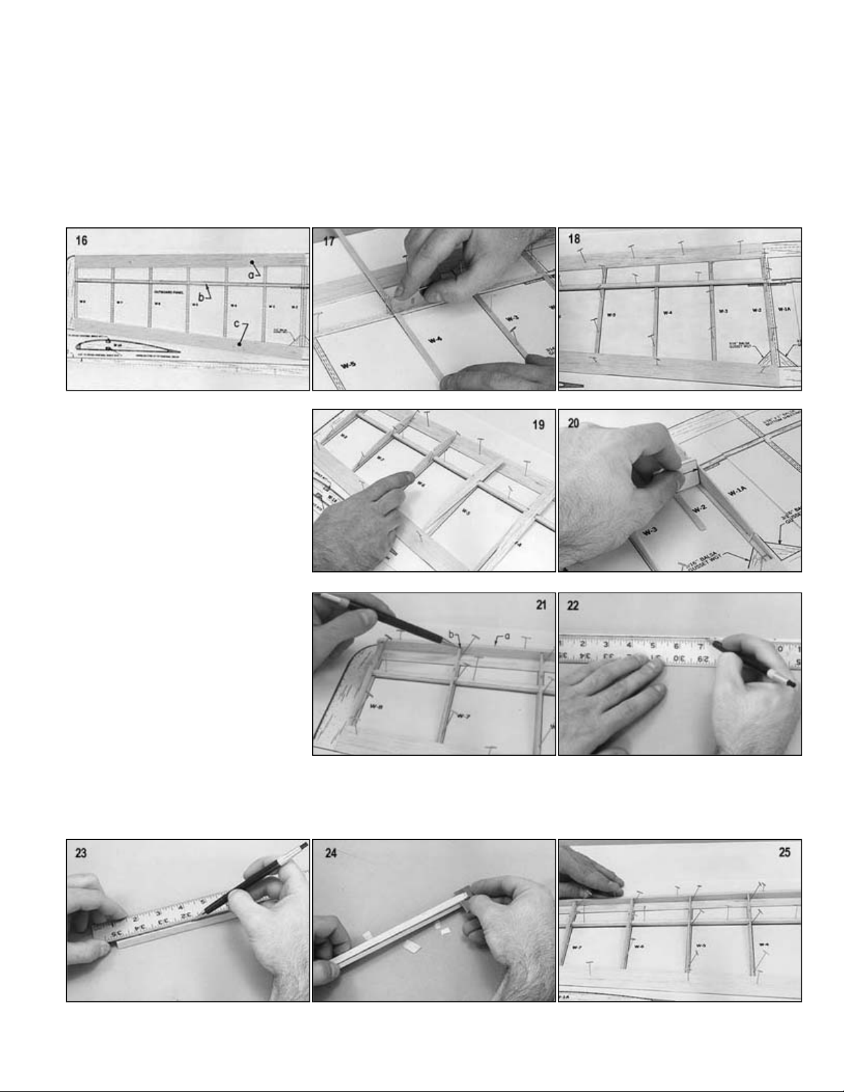
Outboard Wing
c.
Pin down the 1/4"x1" trailing edge over the plans.
17.
Cut pieces of 1/16"x3/16" balsa for the bottom rib cap strips. Glue and pin these as indicated on the plans.
relation to the trailing edge.
16.
18. Glue and pin the 1/8"x1/4" spruce spar on top of the 1/16"x3/16" spar cap strip. Use a few ribs to locate the spruce spar in
a. Pin down the 1/16"x1" bottom sheeting.
b. Pin down the 1/16"x3/16" spar cap strip.
19. Glue and pin down the ribs (except W·2)
in place. Glue the ribs to the cap strips,
spruce spar, planking, and trailing edge
stock.
20. Use the outboard rib guide to angle rib
W·2. Glue and pin W·2 in place. Use a
piece of cap strip stock to put the guide
level with the rib cap strip.
21.
22. Use these marks to draw a line on the
23. Draw a line on the front of the leading
24. Use a single edge razor blade to trim off the excess. Sand with a sanding block to smooth any rough areas.
25. Glue and pin the leading edge in place.
a. Pin but do not glue the piece of
shaped leading edge in place.
b. Use a pencil to mark where the
ribs touch the leading edge.
back of the leading edge.
stock, taking off the same amount.
Page 7
.
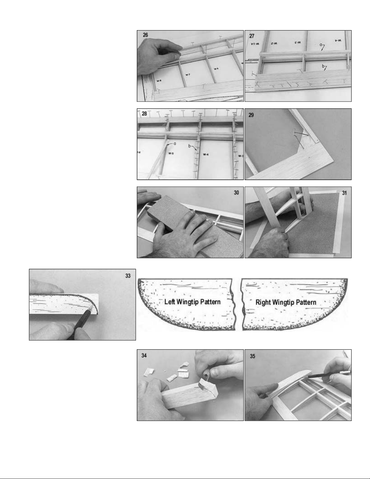
Glue the 1/16"x3/16" top spar cap
joint.
38. Carve the tip block to shape. Sand down to smooth any rough areas.
26. Glue and pin the 1/8"x1/4" spruce top
spar in place.
27.
28. a. Cut pieces of 1/16"x3/16" balsa
29. Glue wing gusset WGT in place as
30. Block sand the entire wing panel to
31. Tape a piece of 80 grit sandpaper to a
a.
strip on top of the spar.
b. Glue and pin the 1/16"x1" top
sheeting in place.
for top rib cap strips.
b. Glue and pin the cap strips in
place.
indicated on the plans.
smooth out any rough surfaces.
flat surface. Carefully sand the dihedral
32. Repeat this process for the tip rib.
33. Trace the wing tip pattern on the
3/4"x1"x6" balsa block.
34. Carve the tip block.
35. Place the tip block against the tip rib.
Trace around it as shown in the picture.
36. Carve the tip block up to the line.
37. Glue and pin the tip block to the tip rib.
Page 8
.
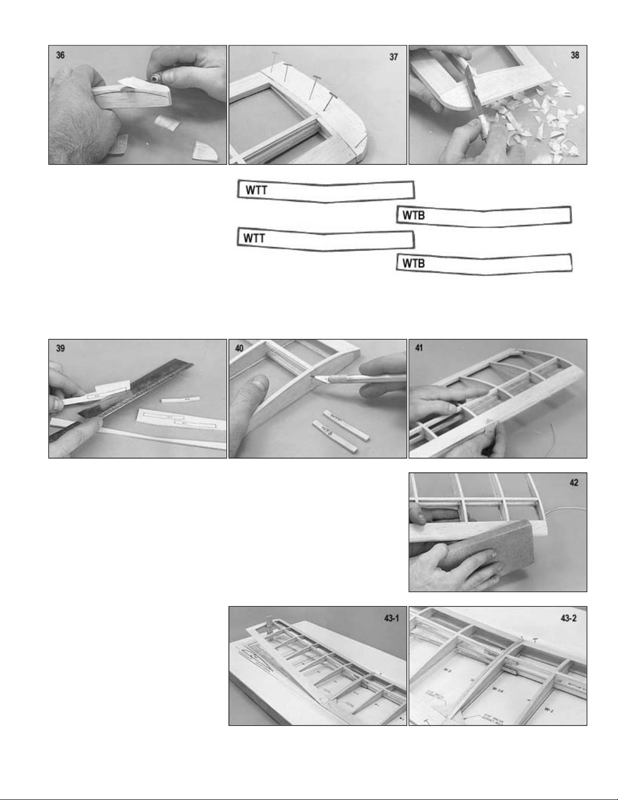
Trial fit the dihedral braces WTT & WTB.
1/4" as shown. If the joint between
glue. Have a "wet" joint to insure that the
wing.
39. Use the patterns supplied to make two
WTT's and two WTB's. Cut these from
the scrap 3/32" die-cut plywood brace
WR.
40.
Trim the ribs if necessary, but do not
glue the dihedral braces in yet.
Repeat these procedures for the other outboard wing panel so that you will have one left panel and one right panel.
41. Carve the leading edge of all wing panels with a single edge razor blade to airfoil contour.
Joining Wing Panels
42. Sand the leading edge smooth with the sanding block.
43. Trial fit WTT & WTB dihedral braces in the inner panels at the outboard rib.
Pin down the inboard panel over the plan. Position the outboard panel on the plan
against the inboard panel and raise the tip rib 2the two panels does not match perfectly, sand one or both of the ribs until it does.
Glue the panels together with epoxy
glue will fill any gaps in the seam. Also
epoxy glue dihedral braces WTT and
WTB in place as shown. After the epoxy
has set up, take up the wing panels and
peel off any excess glue that has
squeezed out. It is easier to do this
before the glue completely cures.
Repeat the same procedure to the other outboard and inboard wing panels. You will now have one left wing and one right
Page 9
.
Glue the panels together with epoxy glue. Have a "wet" joint to insure that the glue will fill any gaps in the seam. Also epoxy
glue dihedral brace WR in place as shown. Be sure to glue it securely to the top and bottom spars. Take up the wing panels
and trim off any excess glue as done when gluing panels together.
46. Cut pieces of 1/16"x3"x36" balsa and finish sheeting the center section of the wing.
Cut pieces of 1/8" sq. balsa to fit between the ribs and glue in place as indicated on the plans and side view drawings. These
STOP: If you wish to add the spoiler option it.js best to do it before proceeding to the next step. (See "Optional Spoilers" at
the end of this section).
44. Position the two wing halves over the
plan. Pin the right half down so that its
inboard panel is flat on the plan. Block
up the left wing half 2-3/4" at the
inboard-outboard joint. If the joint
between the right and left wings do not
match perfectly, sand one or both of the
ribs until it does.
45.
47. Rubber bands can cut into the balsa wood. To protect the area, use pieces of scrap 1/32" plywood and glue into place on
the wing trailing edge as shown.
48. Completely sand the entire wing with fine sandpaper. The wing is now ready for covering.
Optional Spoilers
1.
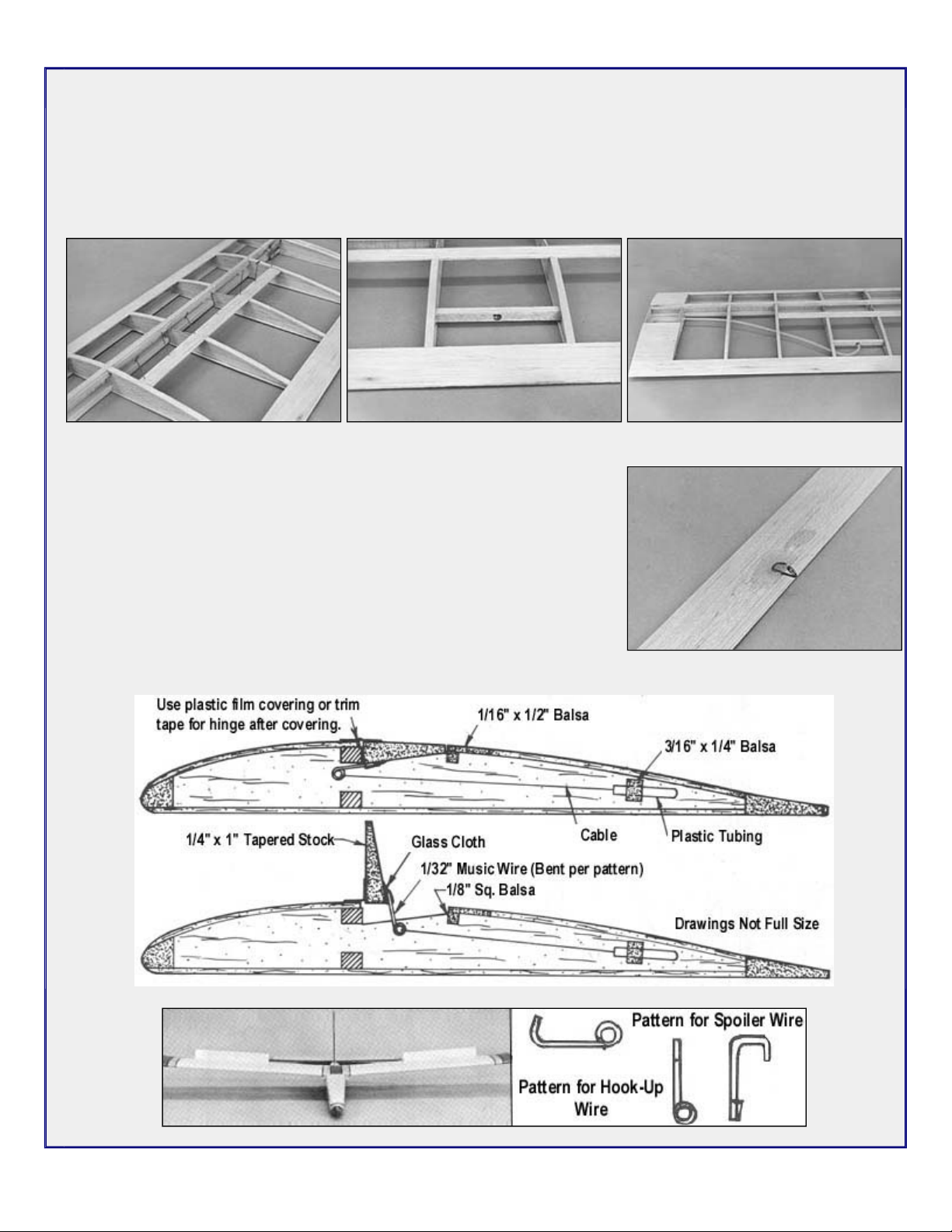
a. Cut to length a piece of 1/4" x 1" trailing edge stock for the spoiler.
b. Cut through the cap strips and ribs (as shown on the plans and side view drawings) to allow the spoiler to fit flush in
the wing. Make these cut outs only in the two center ribs of the spoiler bay.
2.
Trim away the cap strip material from the two center ribs of the spoiler bay to allow for the 1/16" x 1/2" balsa sheeting.
3.
will act as a shelf for the 1/16" x 1/2" balsa sheeting.
Page 10
.
4.
Cut a piece of 1/16" x 1/2" balsa sheeting and glue in place on top of the 1/8" sq. balsa and flush with the top of the wing.
5.
Cut a piece of 3/16" x 1/4" balsa to fit in between the ribs as shown on the plans. Drill a 1/8" hole through the center of it to
allow the plastic tubing to fit through. Glue the balsa piece in place.
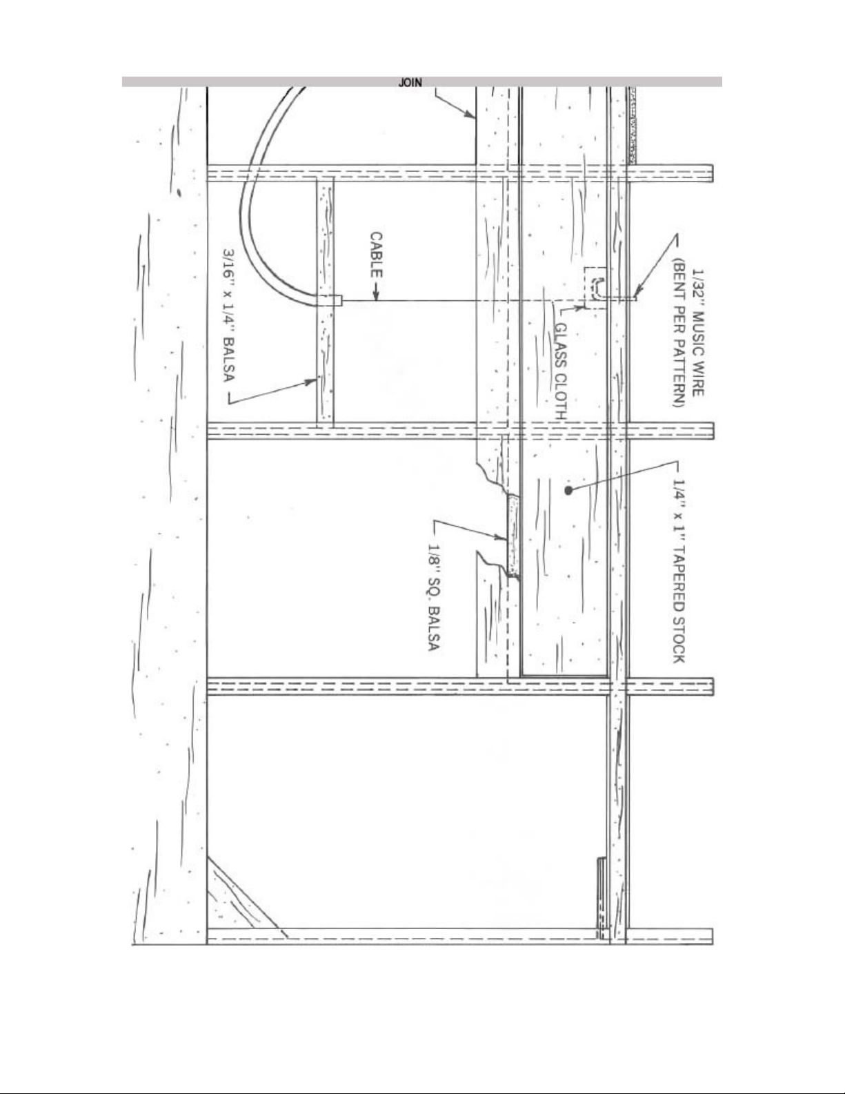
6.
Using heat, pre-bend the plastic tubing to the shape shown on the plans. Drill 1/8" holes through the ribs at the locations
shown on the plans to allow the tubing to pass through. Slip the tubing in and glue in place.
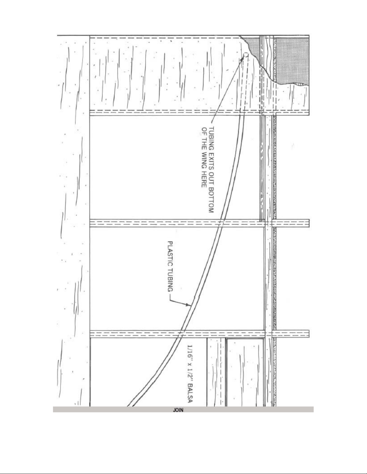
7.
Cut and bend a piece of 1/32" music wire per pattern and epoxy glue in place as
shown on the plans. Also epoxy glue a small piece of glass cloth over the wire.
8.
Repeat this process for the other wing and then continue with the wing
construction.
After covering the wing and the spoilers make hinges for the spoilers out of pieces
of plastic film covering or trim tape and install the spoilers. Feed the cord through
the plastic tubing from the servo hook-up side of the tubing. Connect the cord to
the wire on the spoilers. Make the servo hook-up wire per pattern. Both pieces of
cord from the spoilers are connected to this. The exact placement of the hook
depends on where your servo is installed. Connect the hook to the servo. Both
spoilers should come up at the same time andboth should open the same amount.
Page 11
. . .
Page 12
Page 13
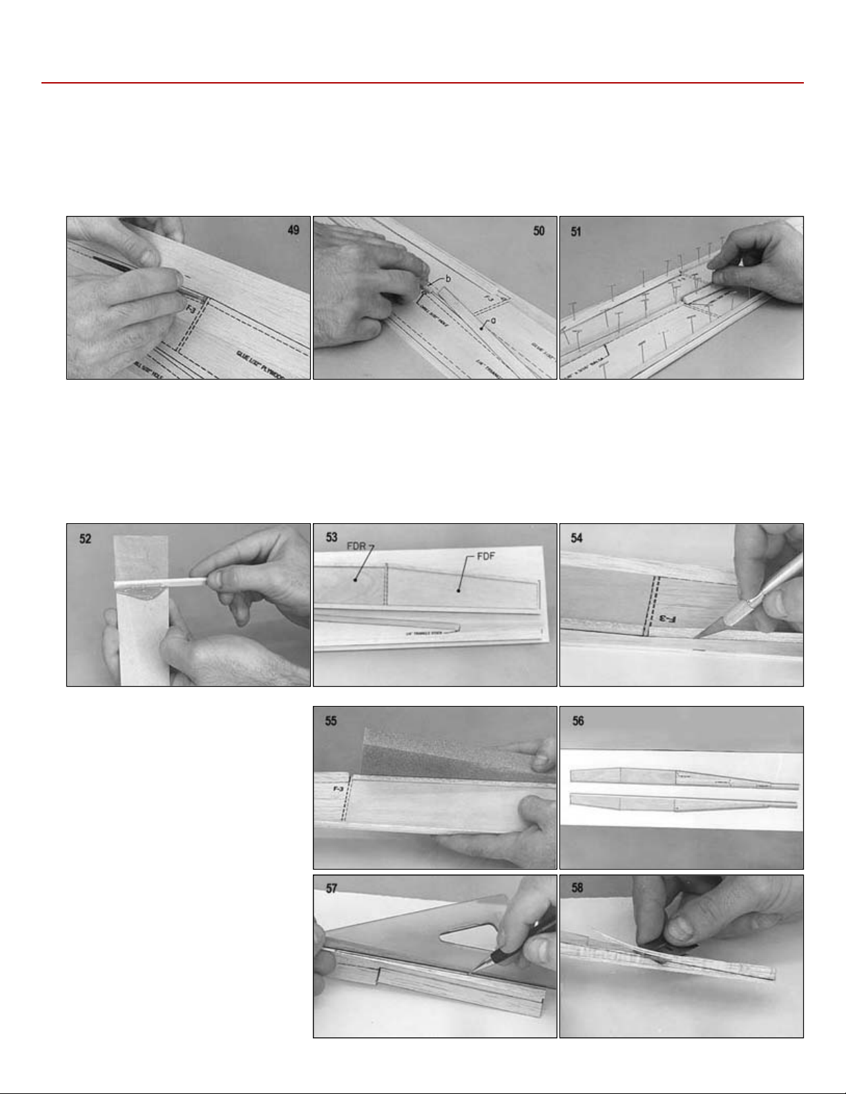
FUSELAGE CONSTRUCTION
glued in place.
b.
1/8"x3/16" balsa as indicated on the printed fuselage sides.
51.
Glue and pin the 1/4" triangle stock pieces and 1/8"x3/16" pieces in place.
procedure for right and left doublers FDR.
54. Cut out the fuselage sides with a knife. Be sure to cut just outside of the lines.
joining.
3
49. Drill or cut out the 5/32" dowel holes in the fuselage sides. This will locate the holes after the plywood doublers have been
50.
52. Using a paddle, spread a thin coat of epoxy glue on both die-cut 1/32" plywood doubler's FDF. Don't use a large amount of
53. Glue one doubler FDF onto the right fuselage side as indicated and the other to the left fuselage side. Repeat this same
a. Cut pieces of 1/4" triangle stock, and
epoxy as this will add unnecessary weight.
55. Use a sanding block to sand the
fuselage sides to final shape. Match the
sides to each other.
56. The fuselage sides are now ready for
57. Refer to the top view of the plans and
draw a line for the bevel at the rear of
the fuselage.
58. Using a single edge razor blade, cut the
bevel at the rear of the fuselage.
59. Epoxy glue plywood formers F-2 and Fin place on one of the fuselage sides.
Use a square to be sure the formers are
perpendicular to the fuselage side.
Page 14
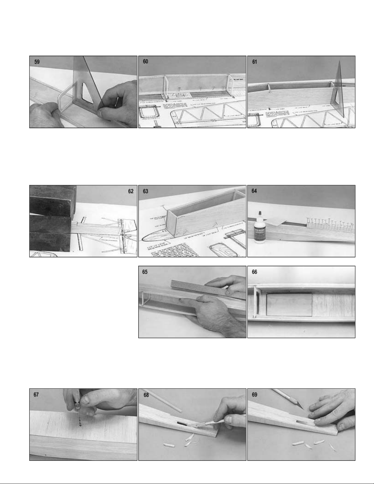
.
60.
Pin the side in position over the top view of the plan.
61. Epoxy glue the other fuselage side to F
-
2 and F
-
3 over the plans. Check with a square before the glue sets up.
sheeted later.
tubing fits tightly.
69. Insert the outer tubing through the slot and push the tubing up through the fuselage into the servo compartment.
62. Pull the fuselage sides together at the rear using square weights (pieces of scrap iron shown here) and glue together.
63. Epoxy glue both sides of F-1 and glue in place over the plans. Pin or use weights to hold the sides until the glue sets up.
64. The bottom of the fuselage may now be sheeted using cross-grain pieces of 3/32" sheet balsa. The top of the fuselage is
65. Use a sanding block to smooth the
rough edges
66. Glue the 1/8" Lite-Ply towhook base in
place as indicated on the plans.
67. Drill a hole for the towhook through the
bottom of the fuselage and the towhook
base. Do not glue the towhook in. It is
best to do this after covering the model
68. It is best to have the tail parts complete at this time so that they may be used for pushrod alignment. Mark the location at
the rear of the fuselage for the exit slot of the rudder pushrod. Cut out the exit slot. Trim around the slot so that the outer
Page 15
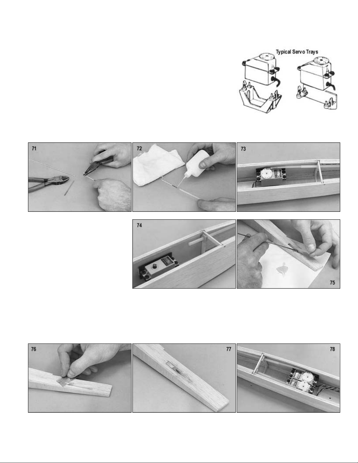
.
Secure the servo, using the manufacturer's mount or mount on hardwood rails. See "Radio Installation" for more information
1/2" at the threaded end of one of the threaded rods. Put a "Z" bend (or a
threaded area of the
servo. This will give an indication of where the outer tubing is to be fastened to F
-
3.
76. Use a single edge razor blade and trim the outer tubing flush with the outside of the fuselage side.
77. Fill in any holes around the pushrod with scrap balsa. Sand flush with a sanding block
79. Sheet the top of the fuselage with pieces of cross
-
grained 3/32" sheet balsa. Smooth the rough edges with a sanding block.
70.
on mounting servos.
71. Cut off 2"L" bend if you are going to use a pushrod keeper) in the nonrod.
72. Clean the threaded area with a rag dipped in alcohol or thinner. This will remove
any oil from the wire. Thread the wire into the inner tubing. Use epoxy or
cyanoacrylate "super" glue to glue the threaded rod into the tubing.
73. Slide the inner pushrod tubing into the outer pushrod tubing. Install the Z-bend through the servo arm and hook it up to the
74. Remove the inner tubing and use a
piece of scrap 1/32" plywood to make a
mounting bracket for the outer tubing as
shown. Epoxy glue this bracket in place
75. Epoxy glue the outer tubing in place at
the rear of the fuselage. Wipe off any
excess glue.
78. Repeat the same procedure for the elevator pushrod. When complete the servo installation should look similar to that
pictured.
Page 16
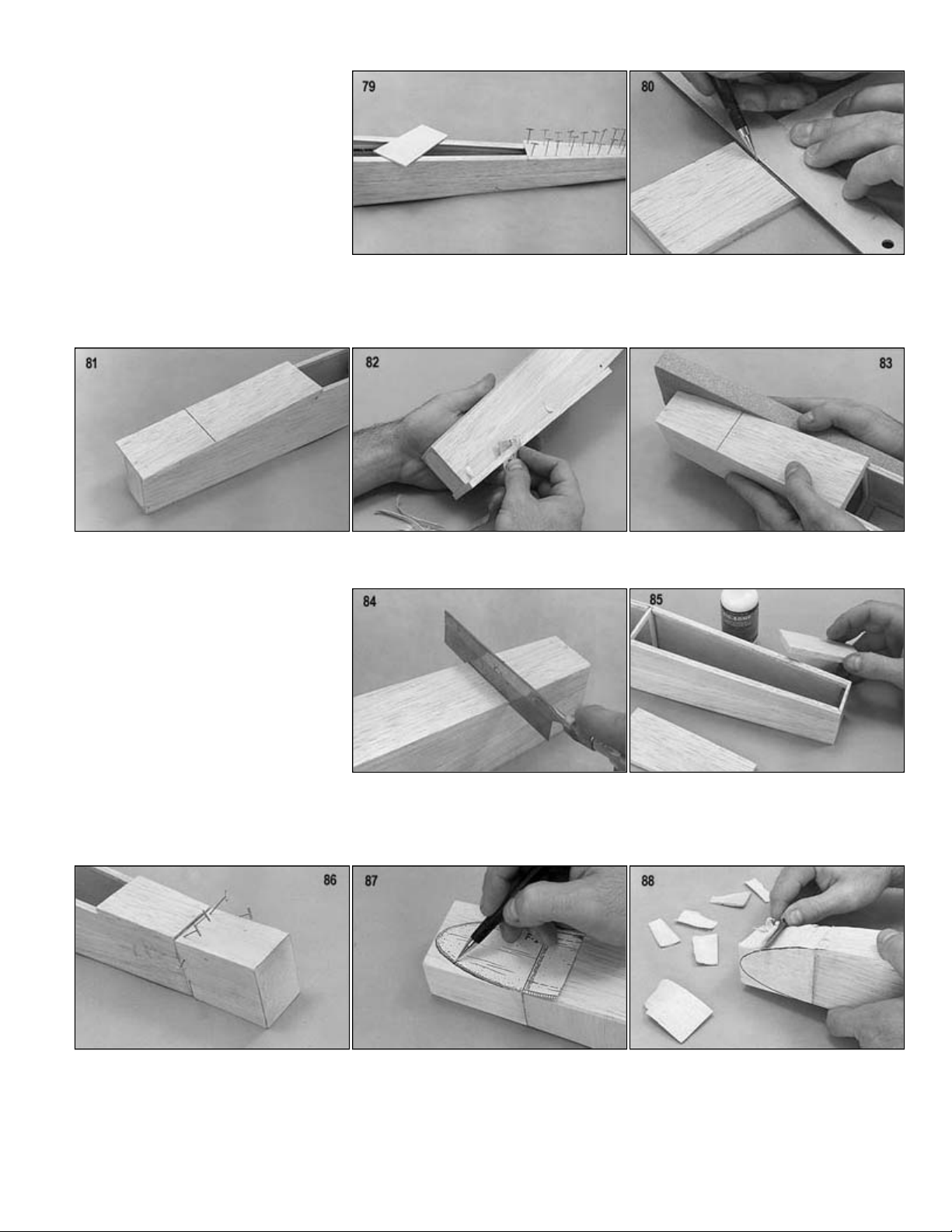
.
balsa). This will indicate where to cut the
82. Use a single
-
edge razor blade to trim the top hatch sheet flush with the fuselage sides.
83. Smooth the rough edges with a sanding block.
84. Saw along the line previously marked to cut the hatch apart from the rest of the top.
and a slight jog at the top of the fuselage
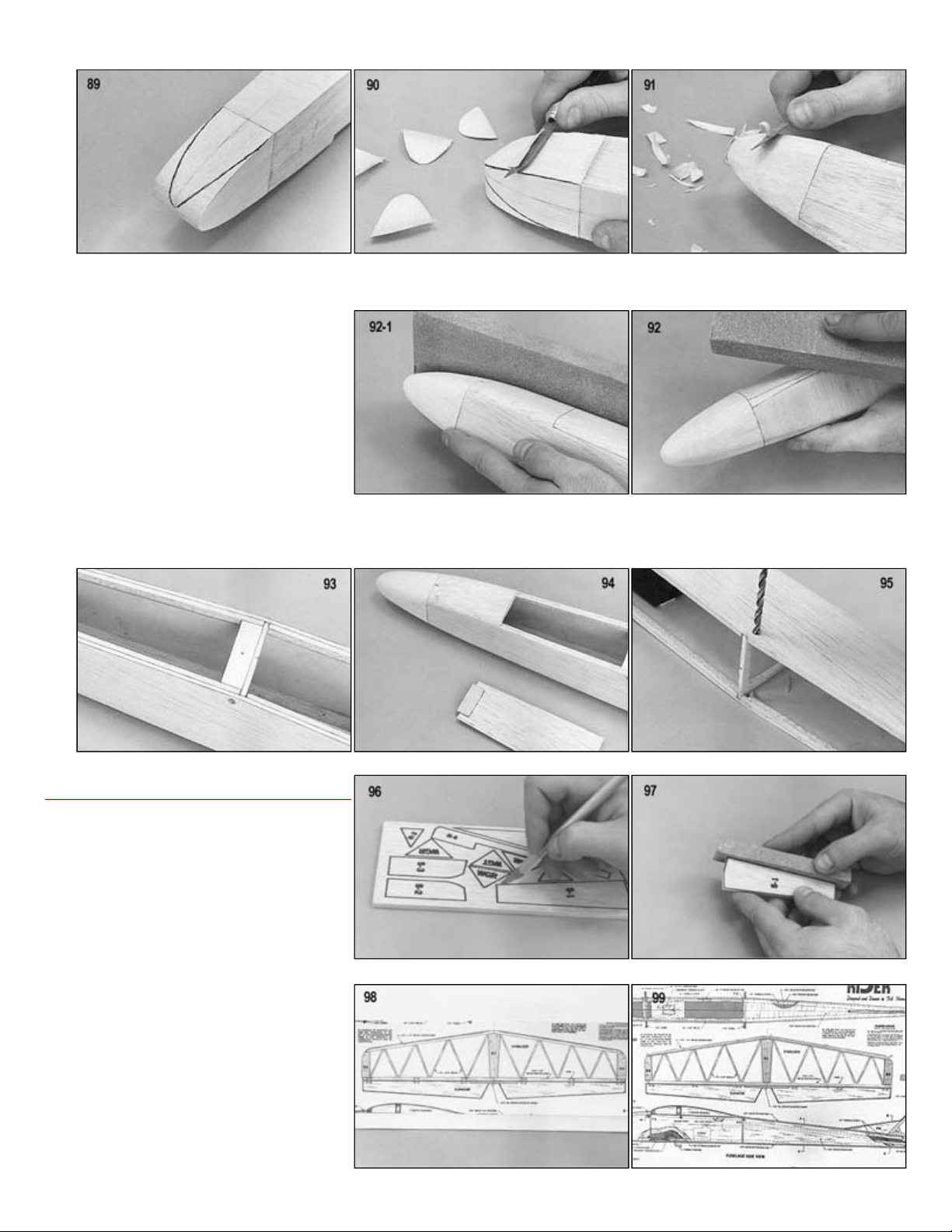
87. Use the nose block side view drawing to trace the pattern on the side of the nose block.
88. Carve the nose block down to the line previously drawn. Note that part of the fuselage top sheet will also be carved.
l, F-2, F-3, rear fuselage) to determine the exact contours. Don't shape the open top of the fuselage where the wing will sit.
80. Mark a line 3" from the end on the
fuselage top hatch sheet (1/4"x2-1/4"x8"
hatch apart from the rest of the top.
81. Tack glue the top hatch sheet onto the
fuselage. The front should be flush with
F-1.
85. Remove the hatch and top sheet from
the fuselage. Permanently glue the top
sheet in place.
86. Glue and pin the 1-1/2"x2"x2-1/2" balsa
nose block to the fuselage. It should be
flush with the bottom of the fuselage,
as shown in the picture.
89. Use the nose block top view drawing and trace it on the bottom of the nose block.
90. Carve the nose block down to this line.
91. Tack glue the hatch in place. Carve the edges of the nose block and fuselage to shape. Use the cross-section drawings (F-
Page 17
.
Remove the hatch and glue in a piece of
92. Block sand all edges to smooth out any rough areas.
93.
scrap 1/8" Lite-ply for the hatch holddown plate "HH" as indicated on the
plans. Drill through hatch for the 256x1/2" hold-down screw.
94. Glue a piece of scrap 1/32" plywood
(hatch tongue) to the front of the hatch
on the bottom side as indicated on the
plans.
95. Drill the dowel holes on through the plywood doublers for the 5/32" wing hold-down dowels. It is best not to glue in the
dowels until after the model is covered. The fuselage may now be covered. Refer to the covering section.
TAIL CONSTRUCTION
96. Use a modeling knife or jig saw to cut
the printed parts out of the 3/16" printed
balsa sheet. Be sure to cut just outside
of the lines.
97. Sand the pieces down to the line with a
sanding block.
98. Pin 5-1, 5-2, and S-3-in place over the
stabilizer plan.
99. Glue and pin the 3/16"x1/4" leading and
trailing edge pieces in place over the
plan.
100. Cut pieces of 1/8"x3/16" balsa for the
cross brace pieces.
Page 18
.
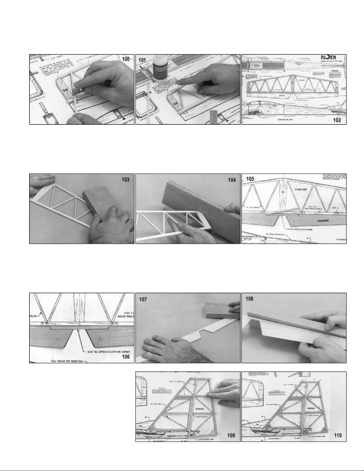
101.
Glue and pin the 1/8"x3/16" cross braces in place over the plan.
102. Completed stabilizer ready for sanding.
106. Glue the spruce joiner in place.
107. Block sand the elevator. Be sure to sand off the printed areas.
108. Round all edges of the elevator with a sanding block. Also round the edges of the spruce joiner.
103. Block sand the stabilizer to smooth any rough areas. Be sure to sand the print off of the wood.
104. With a sanding block, shape the tips as indicated on the plans. Round the leading edge and the tips.
105. Pin the elevators over the plans. Trial fit the 3/16" square x4" spruce joiner.
109. Glue and pin R-4and all pieces of
3/16"x1/4" balsa in place over the plans
for the rudder.
110. Glue and pin R-1. R-2, R-3, and all 1/8"
x 3/16" cross pieces in place over the
plans.
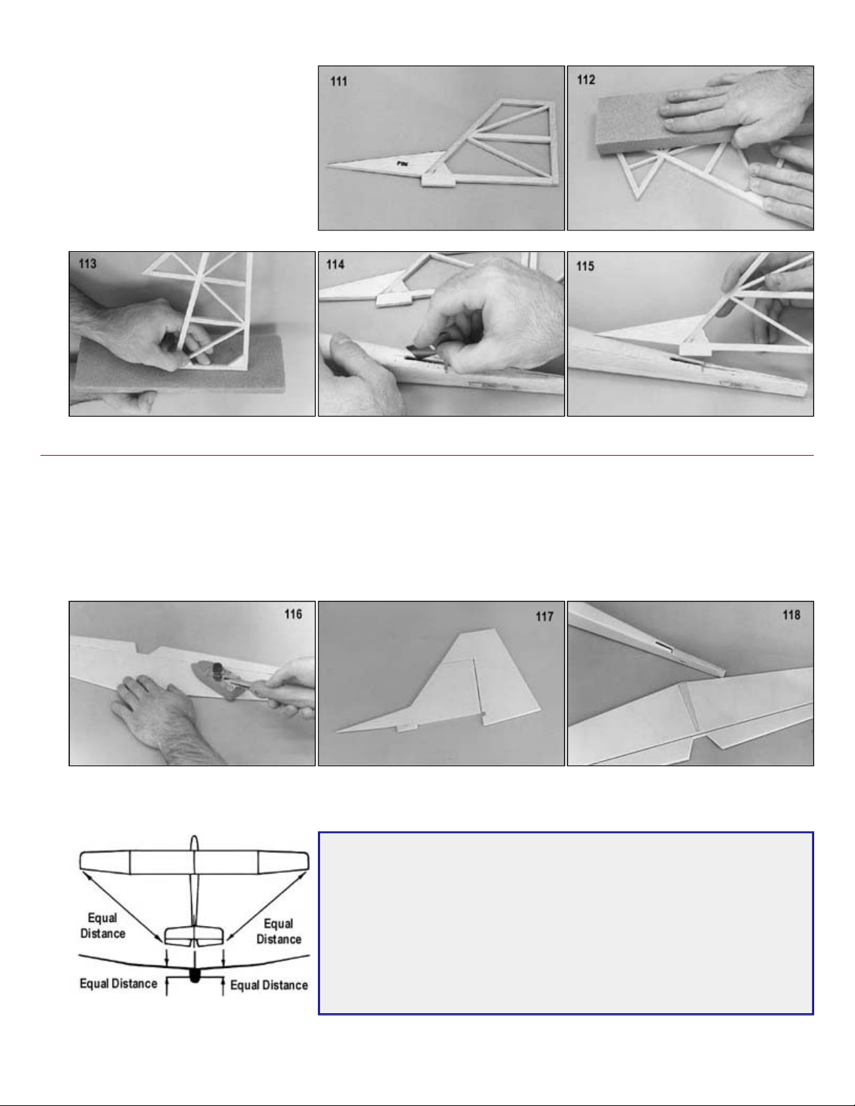
111. Glue the small fin onto the large fin.
Page 19
.
FINAL ASSEMBLY
the Easy Hinges as described below. Use four hinges located as shown on the plan.
117. Cover the fin and rudder as you did in the prior step, and install the hinges. Use two Easy Hinges for the rudder.
glued to the fuselage. This is important to insure wood
-to-
wood contact at the glue joint.
carefully check the alignment as shown in the diagrams.
112. Block sand all pieces.
113. Round all edges with a sanding block.
114. Cut a slot in the fuselage top for the fin
tab.
115. Trial fit the fin tab into the slot. Do not
glue the fin into place yet.
116. Cover the stabilizer and elevator using the procedures outlined in the "COVERING" section. Once they are covered, install
118. Use a sharp knife or razor blade to carefully remove the plastic film covering on the bottom of the stabilizer where it will be
119. Position the wing on the fuselage. Use Kwik-Set (5-minute) epoxy to glue the stabilizer to the fuselage. As the glue dries,
Hinging The Control Surfaces with Sig Easy Hinges
Sig's famous EASYHINGES have been included with your Riser kit for
hinging the rudder and the elevator. Even though they are obviously super
thin, EASYHINGES are actually a three-part laminate. The tough, plastic inner
core is sandwiched by an absorbant wicking material. The hinges have also
been chemically treated to slow down the drying time of the thin CA (which is
normally instant) to about five minutes. This extra time allows the CA to soak
all the way down to the end of the hinge and into the wood surrounding it.
Once the glue has dried, the hinge cannot be pulled from the control surface
without tearing wood out with it.
Page 20
.
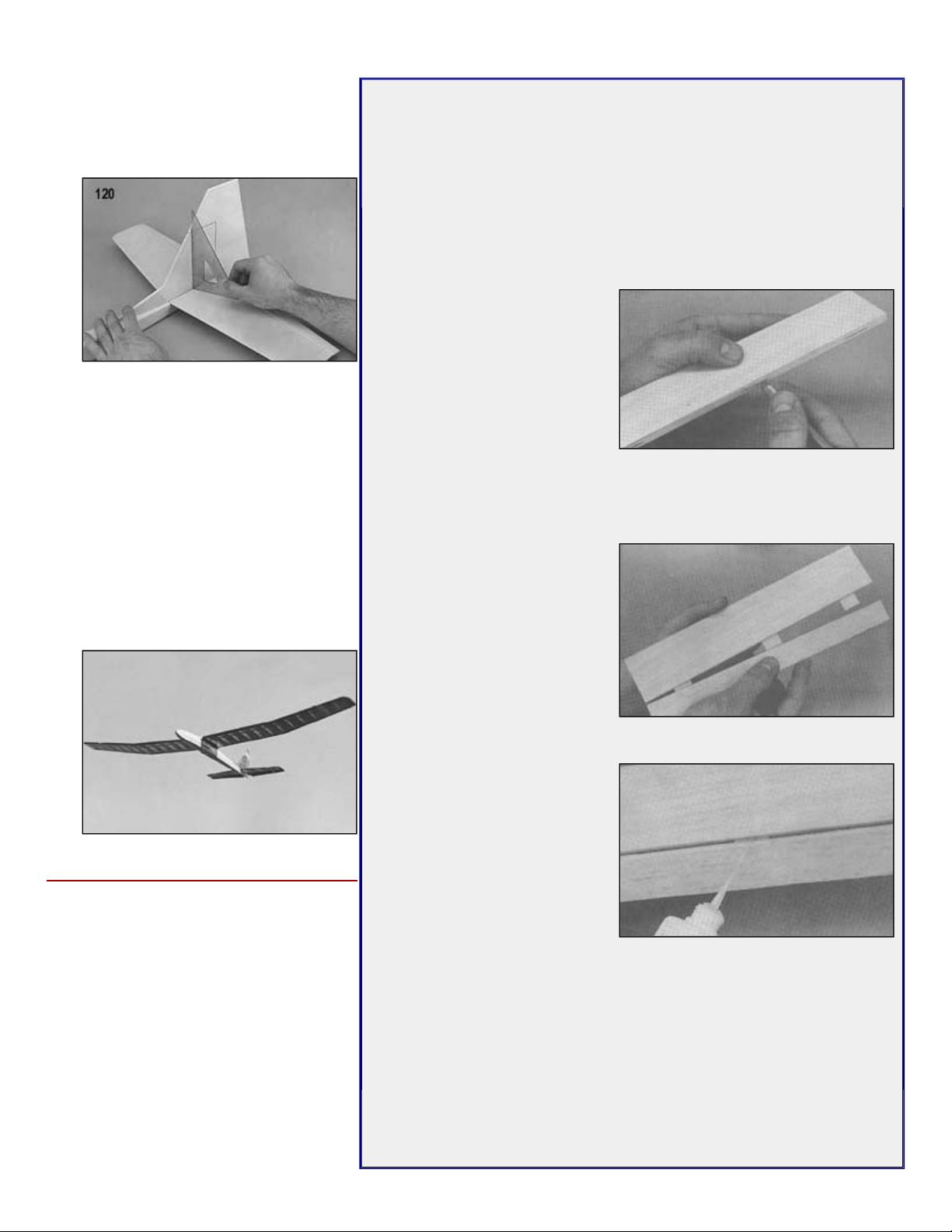
the fin makes contact. Epoxy glue the fin
in place. Use a square to make sure that
wish.
Although other brands will work, we
application. To cover the RISER, you will
120. Remove the covering material from the
top of the stabilizer and fuselage where
the fin is perpendicular to the stabilizer.
121. Glue the two 5/32"x3" wing hold-down
dowels into the holes you drilled earlier.
The exposed ends of the dowels can be
painted to match the covering, if you
122. Use epoxy to glue the formed wire
towhook and the hardwood towhook
block in place on the fuselage.
NOTE: If you would prefer to use a
commercially-available adjustable
towhook, install it now on the plywood
towhook base plate.
COVERING
The RISER design is ideally suited to
use a plastic iron-on covering material.
recommend Sig Supercoat Covering for
its light weight, low cost, and ease of
need at least two rolls of Supercoat. For
that finishing touch, use Sig Super Trim
self-adhesive trim sheets to add a bit of
trim color.
If you choose another brand of covering
material, be sure to read the
manufacturer's directions that come with
the material.
Developed from the start to take advantage of the popular cyanoacrylate
adhesives, EASYHINGES are fast, strong, and lightweight. With these hinges,
there is finally a solution to the dreaded, tedious job of hinging control surfaces.
No more gouging and picking to make oversize slots in the wood. No more
messy epoxies to bind up the hinge joint. Simply follow the instructions here
(which may very well take longer to read than to do!) and you will probably
never want to use another type of hinge again.
Hinging Instructions
1. Use the plans to mark the hinge locations on the tail surfaces. Marks
made with a felt-tip pen can later be wiped off the plastic covering.
2. Next, using a #11 X-Acto
blade (or similar) cut a slot
approximately 1/2" in depth
and slightly wider than the
hinge. Continue cutting all of
the slots in both pieces to be
hinged.
3. After all slots have been cut,
insert an EASYHINGE
halfway into each slot in one of the pieces to be hinged. Then carefully
slide the matching model part onto the other half of the hinges. You'll
find it easiest to slide the part onto the hinges at an angle, one hinge at
a time, instead of trying to push it straight onto all the hinges at once.
4. At this point the surface to be
hinged is attached but not
glued. Align the two surfaces
and adjust the gap between
them as required. For best
control response, the gap
should generally be as small
as possible but big enough to
allow the control surface to
move to the maximum
deflection that you will
require.
5. Place three or four drops of
any brand cyanoacrylate
adhesive (thinnest variety)
directly onto the EASY
HINGE in the gap. You will
notice that the glue is quickly
wicked into the slot as it
penetrates both the wood and
the hinge. Continue this
process, gluing the same side
of all of the hinges. Then turn
the surfaces over and repeat the gluing process on the other side of
each hinge.
6. After the glue has cured, approximately five minutes, the joint can be
flexed. You may notice a slight stiffness in the joint. This can be
eliminated by flexing the surface to full deflection each direction a
couple of dozen times. Don't worry about shortening the life of the hinge
as they are almost indestructible.
NOTE: The photos show the hinges being installed on a sample piece of bare
wood. For your Riser, we recommend that the surfaces be covered before
hinging. Simply cut the slots and proceed with the steps described below as if
the covering wasn't even there!
Page 21
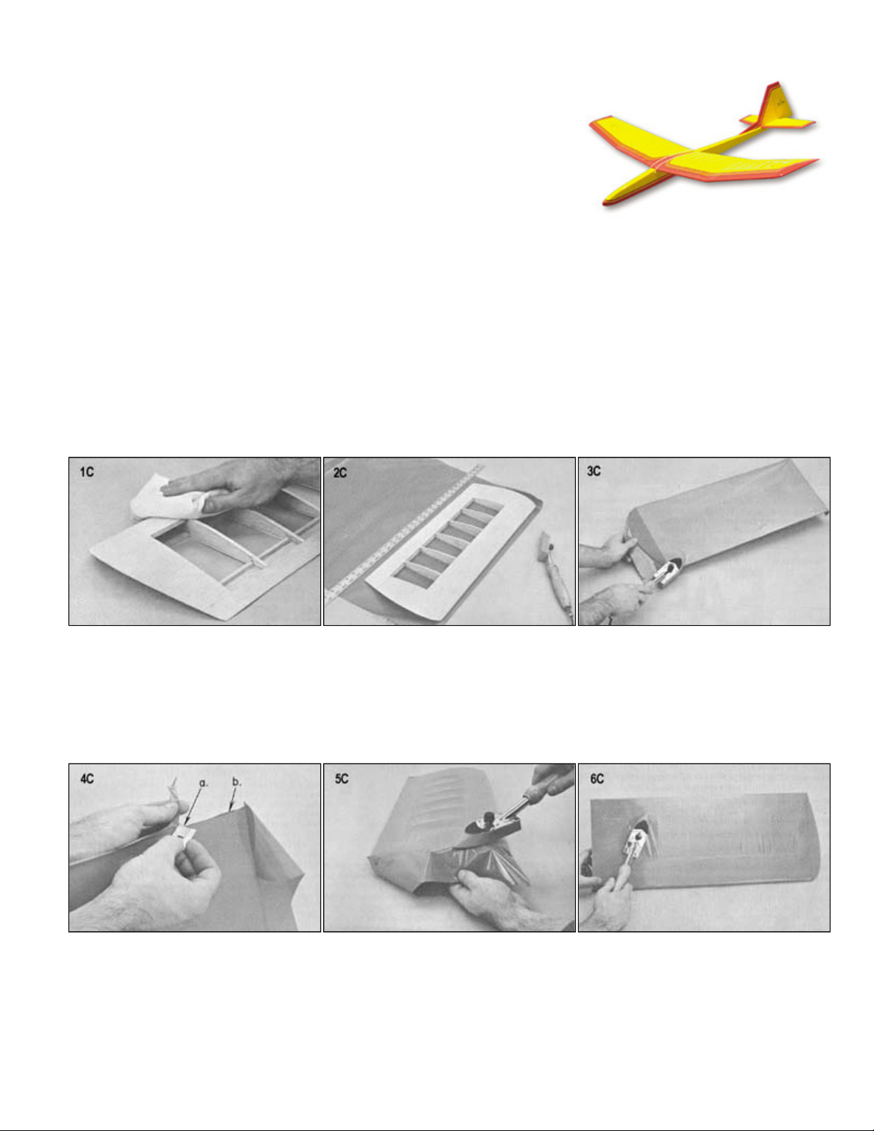
.
NOTE: Cover the bottom of the wing first and then the top of the wing. This leaves the overlapping seam on the bottom.
before beginning to iron.
NOTE: Wipe surface of iron periodically to remove any colored adhesive that may ooze from the covering material.
5.
Repeat the process on the top of the wing.
A heat gun could also be used to shrink the covering. Keep it moving
held too close. Don't hurry the process.
under the covering as it is applied.
Follow their instructions closely when applying the material, as different brand
coverings can have slightly different handling characteristics and application
temperatures. However, the basic techniques for applying iron-on plastic
coverings of any brand are similar, and the following hints and photos should be
helpful.
NOTE: The structure shown is of a different model but the same procedures are
used.
1.
The structure that is to be covered must be clean, dry, and dustfree. Sand all surfaces smooth with fine sandpaper.
Remember that the covering material cannot hide poor workmanship. Wipe the entire surface with a tack rag or a cloth
dampened with alcohol to remove all excess dust.
2.
Cut the covering material to the required size allowing approximately one inch excess around the edges. Remove the
plastic backing and lay the adhesive side of the covering material against the structure. Have it as smooth as possible
3.
Tack down at several places along the outside edge. Next seal the entire edge of the structure. Don't try to shrink the
covering tight until later.
4.
a. Trim off the excess with a razor blade or a modeling knife.
b. Seal the loose edges down with the iron.
6.
Shrink the covering in the inner areas with the iron. Keep the iron moving, allowing the heat to shrink the covering at the
same rate. To keep the covering from "ballooning-up", put small pin-holes in each rib bay on the bottom of the wing.
7.
- 4" to 6" above the surface. It will melt the covering if
8.
Seal down all over-lapping seams and edges.
NOTE: The wing instructions refer to built-up structures with open framework areas. When covering sheet surfaces better
results may be obtained by starting at the center and working toward the outer edges. This allows the air to escape from
Page 22
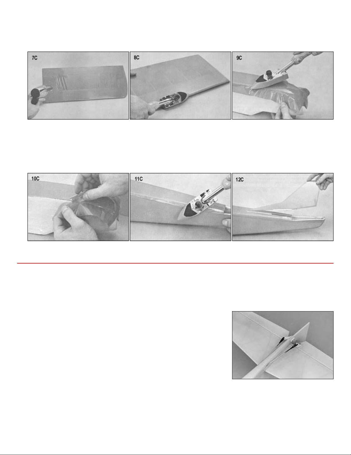
.
curve. Work slowly and cover small sections at a time.
10. Trim off excess and seal edges. Repeat this procedure on the sides. Allow about 1/8" to 1/4" overlap for a fuel
-
proof seam.
11. Cover the top and seal down all edges.
applied over seams to seal them.
RADIO INSTALLATION
instructions supplied with your radio.
Mounting Servos In The Fuselage
pushrods. Screw the servos to hardwood mounting rails that are epoxied across
generally accepted that the servo rail method of servo mounting is more secure in the long run.
9. Cover the bottom of a fuselage first. When doing compound curves, as on the nose shown here, be sure to leave extra
material around that area. Grip the covering and apply heat. As the covering becomes pliable pull the covering around the
12. Remove covering from areas to be glued. There must be wood-to-wood contact in the glue joints. Strips of covering may be
The following information can be used as a guideline for mounting your radio in the RISER. The methods described below
are fairly standardized and should work well with any system, although you should read and follow the manufacturer's
The rudder and elevator servos should be mounted side-by-side in the wing
opening so that the output arms are lined up with the ends of the nylon
the inside of the fuselage. We recommend that the hardwood mounting rails be
made of 3/16"x3/8" spruce, pine, or basswood. Do not make the rails out of
balsa! Glue scrap pieces of balsa to the fuselage sides around the ends of the
mounting rails so that they can never come loose in flight. If you plan to use the
optional spoilers, the third servo should be mounted forward of the flight control
servos.
You can also use foam servo mounting tape and stick the servos to the fuselage sides. For the best bond to the fuselage,
coat the balsa where the servo will be seated with a thin film of epoxy. Although this method is quick and easy, it is
Page 23
.
Elevator And Rudder Hookup
Attach a small nylon control horn to the rudder and another to the elevator using #2x1/2" sheet metal screws. Mount the
The inner nylon pushrod must be trimmed to length before it can be hooked up. With the servo arm and the control surface
Repeat this procedure for the remaining pushrod.
Receiver And Battery Installation
Wrap the receiver and the battery pack separately in foam rubber (such as SIGRF240), held on with rubber bands or tape,
enough to hold the battery and receiver firmly in place so that they will not shift around in flight.
side to activate the internal switch. Lastly, make certain that the charging jack is easily accessable inside the fuselage.
Pre-Flight
amounts of control surface travel. By moving your pushrod linkages into a different hole of the control horn and/or into a
rudder control horn to the left side of the rudder and the elevator control horn on the bottom of the right elevator half, as
shown on the plans.
Slide an inner nylon pushrod into its outer sleeve and attach the Z-bend to the servo arm as you did in Step 73. Be certain
to completely tighten the small servo screw that holds on the servo arm.
held in neutral, cut off the nylon tubing 1-1/4" from the control horn. To keep the exposed inner portion of the nylon
pushrod from flexing, it must be supported by the smooth end of the threaded rod. Cut a 2-56 threaded rod to the required
length and screw it into the nylon pushrod about five or six turns. Lock it in place with a couple of drops of thin CA.
Screw the clevises provided in the kit onto the threaded rods.
NOTE: Depending on our supply at the time of packing, your kit may contain nylon clevises instead of the metal clevises
shown in the photo.
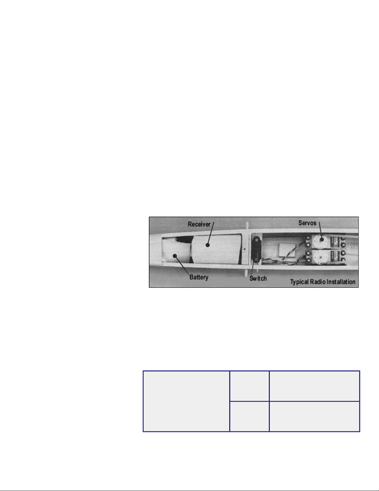
to protect them from damage. Locate the battery pack as far forward in the nose as possible. Position the receiver right
behind the battery. The weight of these components will help to balance the RISER.The foam rubber should be thick
The receiver antenna can be run out of the
bottom of the fuselage and taped at the aft
end; or run out of the top hatch and
connected to a straight pin on the fin using
a small rubber band. The switch can be
mounted directly on the fuselage side
(locate it so that you won't accidentally
touch it during launch). If you prefer, the
switch can be mounted internally as
shown in the photo. Use a short piece of
music wire poked through the fuselage
Be certain to range check your radio equipment according to the manufacturer's instructions before attempting test
flights. If there are any problems, send the radio in to be tuned or repaired. Various brands of servos can give different
different hole of the servo arm, you can change the total amount of control surface travel you'll get when the transmitter
stick is moved to the full throw position. Adjust your pushrod linkages to produce the amounts of movement listed
below. Measurements are made at the trailing edge of the control surfaces at their widest point.
The control surface measurements
listed should give you plenty of control
during your first flights without being
overly sensitive. Test flights may
indicate a need for slightly more or less
movement, depending on individual
model performance and personal
preference.
RECOMMENDED
CONTROL
SURFACE MOVEMENTS
For test flying, the following
are suggested:
ELEVATOR 3/8" UP and 3/8" DOWN
RUDDER 1-1/4" LEFT and 1-1/4" RIGHT
Before flying, you should also adjust all your pushrod linkages so the control surfaces are in neutral position when the
transmitter sticks and trim levers are centered. After the first test flight, readjust the linkages if necessary so that the trim
levers can be returned to neutral position. It may take several flights before exact trim is established on all the flight
controls.
Page 24
.
Airplanes Must Be Straight And Balanced
(or straighten up and fly right!)
wingtips equal distance above the table. Let go and observe which wing panel
with the balance point too far back, which could make the model unstable and
FLYING THE RISER
First Test Flight
left rudder.
One of the secrets to a good flying model is to make sure the wing is straight
and the model is properly balanced. Check to make sure there are no warps in
the wing. If there are, twist the wing in the opposite direction of the warp and
apply heat to both sides of the covering material, starting on the side opposite
the warp. Hold until the covering cools, then recheck for straightness. Try again
if necessary. It is helpful to have a friend assist you with this procedure.
The spanwise balance of the wing is an often overlooked but essential part of
balancing a model. Place your assembled RISER wing on a flat table with both
falls to the table. Add very small amounts of weight to the opposite wing tip until
it will balance on the dihedral joint at the center of the wing. Permanently install
the weights in the wing tip.
To check the fore and aft balance of your model, mount the wing on the
fuselage. The fuselage side view plan shows the location for balancing your
Riser. For the first test flights, you should balance the Riser slightly forward
(1/8") of the point shown on the plans. For everyday flying, you may want to
adjust the balance point. A more rearward balance point or Center of Gravity
(C.G.) will give the Riser a flatter glide but it will also make it more sensitive to
control movements. A forward C.G. will make the controls less sensitive and the
model more stable for better wind penetration with a very slight loss of thermal
capability. Balance the Riser to suit your needs and style of flying. Move the
battery pack and receiver fore or aft to locate the C.G. where you want. After
flying your Riser, you may want to readjust the final balance to achieve the
desired performance. Every model will fly a little different! Never change the
C.G. position more than 1/8" between flights. Do not attempt to fly the model
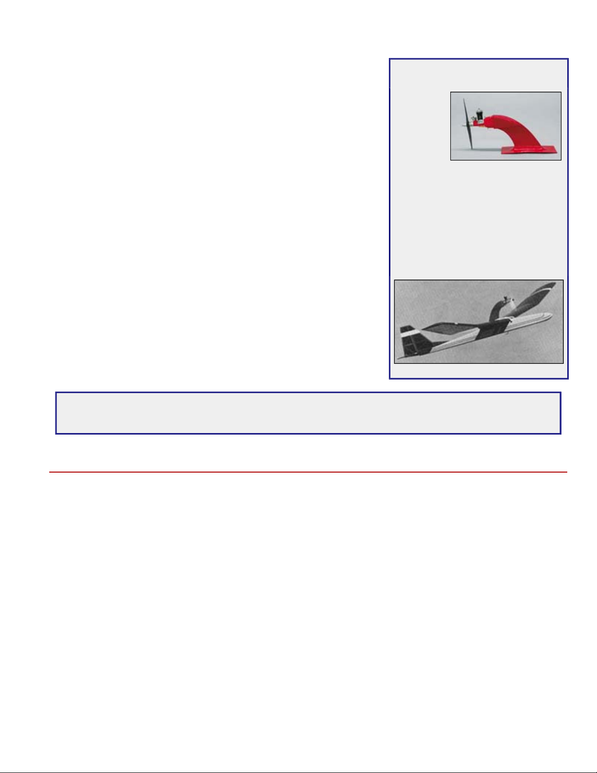
OPTIONAL RISER POWER POD
An
alternative
to the high
start or
winch is to
use one of
these easyto-build Sig Power Pods. The pod's
main advantage is that it requires much
less room than the other launching
devices. You can mount any reed valve
or rotary-valve .049 - .051 engine (not
included) for safe, dependable
launches. The pod is held on by the
wing rubber bands so it can be easily
removed whenever you want. Order No.
SIGSH660.
uncontrollable.
"A model or radio that is not prepared and working properly on the ground before takeoff will not improve in the air -
IT WILL GET WORSEI
There is no point in attempting to fly until everything is 100% correct,"
While it is possible that a R/C sailplane can be mastered by a beginner without any assistance, the odds of success are
pretty slim. Don't be too proud to ask for advice and help from more experienced fliers. A little help at the right time from an
instructor can get you out of trouble and possibly save your model from a bad crash.
Choose an area that is free of obstructions such as buildings and trees and pick a day when there is little or no wind.
Fasten the wing to the fuselage with eight #64 rubberbands. Place six of the rubberbands on parallel to the ribs and
crisscross the final two. If your flying site is occupied by other fliers, check with them to be sure that your frequency won't
interfere with theirs, and vice-versa.
Turn your receiver and transmitter on and fully extend the antenna. Gently hand toss the sailplane into the wind with the
nose pointed slightly down and the wings level. Start by running a couple steps with the model, then release it with a
smooth spear throwing action. Aim for a spot on the ground about 50 yards out ahead of you.
DO NOT THROW THE SAILPLANE VIOLENTLY!
If the nose of the sailplane pitches up, feed in some down elevator. If the nose pitches down, feed in some up elevator.
DO NOT OVER CONTROL!
Keep your control movements smooth. If the sailplane veers left, feed in some right rudder. If it veers right, feed in some
Page 25
.
slow the model and establish a gentle descent. The model should settle onto the ground in a slightly nose high attitude.
wind is light. Many times you can feel the
shot" the glider into
the sailplane into the air. Feed in a small amount of up elevator after the launch and the sailplane will begin to climb
A winch is a battery operated device that uses an electric motor to drive a large spool that reels in the long
The main thing to remember when flying a sailplane is not to over control. If the model does get out of control, and you
have sufficient altitude, a glider is so stable that you can usually just let go of the sticks momentarily and the model will
right itself. Many models have crashed because a beginner continued to send the wrong input. On landing, when the
sailplane is about two feet from the ground, make sure the wings are level and start slowly feeding in some up elevator to
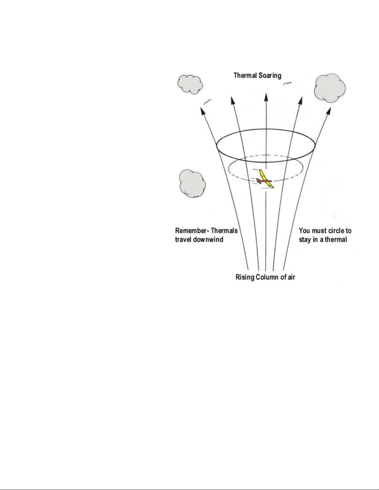
Thermal Soaring
Thermal soaring is by far the most popular type of
R/C soaring. It is not uncommon to see two or
more sailplanes riding the same thermal, all of
them circling for altitude and staying in the
thermal. A thermal is a rising column of hot air - air
that has been overheated by the sun radiating off
dark areas of ground such as roads, plowed fields,
buildings, etc. Thermals can be found year around
and just about anytime of the day. However, the
most active time for thermals is during the spring
and summer months with mid-morning to midafternoon being the best time of day to find them.
Thermals are easy to detect on days when the
temperature difference when the warm thermal air
passes by you. Often a low fluffy cumulus cloud
indicates the location of a thermal. Also watch for
large birds (hawks, gulls, eagles, buzzards, etc.)
circling and maintaining their altitude without
flapping their wings. They are riding a thermal!
Thermals are normally small near the ground and
tend to increase in diameter the higher up they go.
To get into a thermal, we must first gain some
altitude. There are two commonly used methods
of launching a sailplane into the air.
HIGH-START: A high-start is made up of surgical tubing and nylon cord. Its purpose is to "slingthe air like a large rubber band launched model. High-starts come in several different sizes to match the class of
the sailplane being flown - a two meter class or standard class hi-start is recommended for the RISER. The
standard class high-start usually consists of 100 feet of rubber surgical tubing and 350 feet of nylon cord (although
some brands may differ slightly). The surgical tubing is fastened to a stake pounded into the ground. The other end
of the tubing is then tied to the nylon cord, while the other end of the nylon cord has a small parachute attached to
it. The high-start is layed out on the ground directly into the wind. The parachute end of the high start is attached to
the sailplane's towhook. Start walking backwards with the model, stretching the high-start as you go. Go back until
the high-start has been stretched to a maximum of 800 feet.
With the sailplane pointed at the stake, raise the nose to approximately 30 degrees and level the wings. Firmly toss
to the maximum height of the high start. If the sailplane veers to the left or right correct it with opposite rudder. DO
NOT OVER CONTROL! If it constantly veers from side to side and is hard to control, you are probably holding too
much up elevator. Back off a little to regain good directional control. As the sailplane reaches the top, the line
should drop off by itself. If it doesn't, feed in a little down elevator to allow the sailplane to dive slightly and the line
will fall off. Pull back on the elevator to level off so you can start trimming for the flattest glide.
WINCH:
towline. There is no rubber surgical tubing involved. As the line is reeled in, it pulls the sailplane up to altitude. The
speed of the winch is normally controlled by the glider pilot using a foot pedal as he flies the model with his hands.
Most competition oriented sailplane enthusiasts prefer a winch launch over a high-start simply because they can
control the speed that the line is reeled in and thus better control the speed and pull on their model. A practiced
winch operator can often get his sailplane to greater heights than with a high-start.
Page 26
.
wing or the other bump up, immediately turn towards the high wing to try to get into the thermal that caused the bump.
Although there are many special aerobatic slope soaring designs around, the RISER can give a pretty good account of
have a fair amount of altitude, then fly the sailplane behind the slope, and make a gentle descent to a landing on top of the
It will take a little practice to master the art of slope soaring, but it is well worth the effort and a lot of fun.
Now that the sailplane is at altitude, it is time to go thermal hunting. Start by trimming the RISER for a nice flat glide and
head upwind flying a zig-zag pattern. Never cover the same ground twice while searching for thermals. Be looking for
areas where you can see heat waves radiating up, or hawks circling, or swirling "dust devils" being picked up off the
ground. Remember, smooth flying is the secret to long flights. Watch the sailplane closely as it is flying. If it suddenly
seems to "rise up on a step", stops sinking and starts gaining altitude, you know you are in a thermal. Or if you see one
Once you are in a thermal, feed in a small amount of rudder trim to set the sailplane up for a large glide circle of
approximately 100 to 200 feet diameter. As the sailplane continues to gain altitude, you can open up the glide circle
slightly. Once in the thermal, do not let the sailplane get so far downwind that you can't get it back to the field if the lift dies
out.
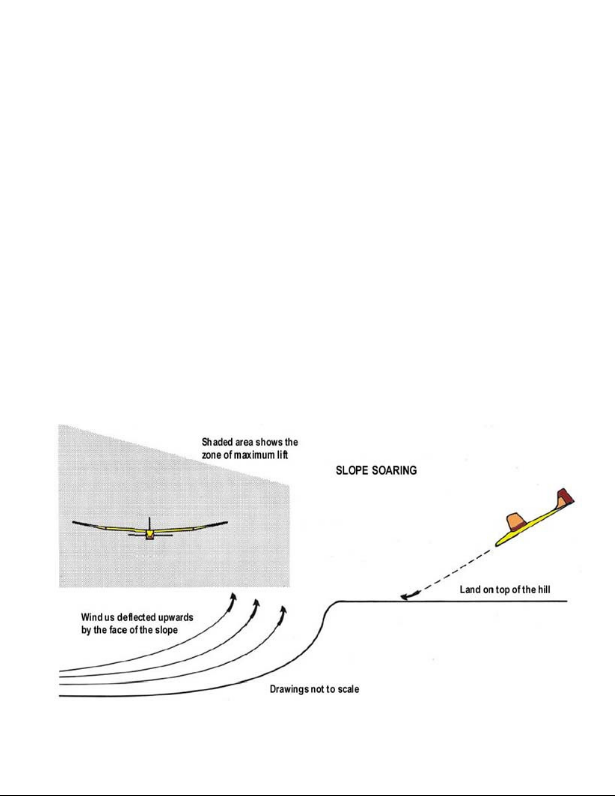
Slope Soaring
Slope soaring is a unique sport in itself and probably the fastest growing aspect of R/C soaring. Wherever you can find a
decent size hill with a 1015 m.p.h. wind blowing into it, you can slope soar. When the wind is blowing into the face of the
hill, it is deflected upward by the slope of the hill. This upward rising air is the lift we use to soar on. Wind velocity and the
amount of slope in the hill will determine the amount of lift generated by a particular site. The amount of lift can also be
affected by obstructions such as trees, buildings, etc. So try to pick a hill with a long smooth approach to it that is free of
obstructions.
itself at slope soaring for duration. The only addition you need to make to your RISER for slope soaring is to add some
ballast to help it penetrate the wind. Depending upon the actual velocity of the wind on the day you are flying, try adding 6
- 12 ounces of weight inside the fuselage directly over the C.G.
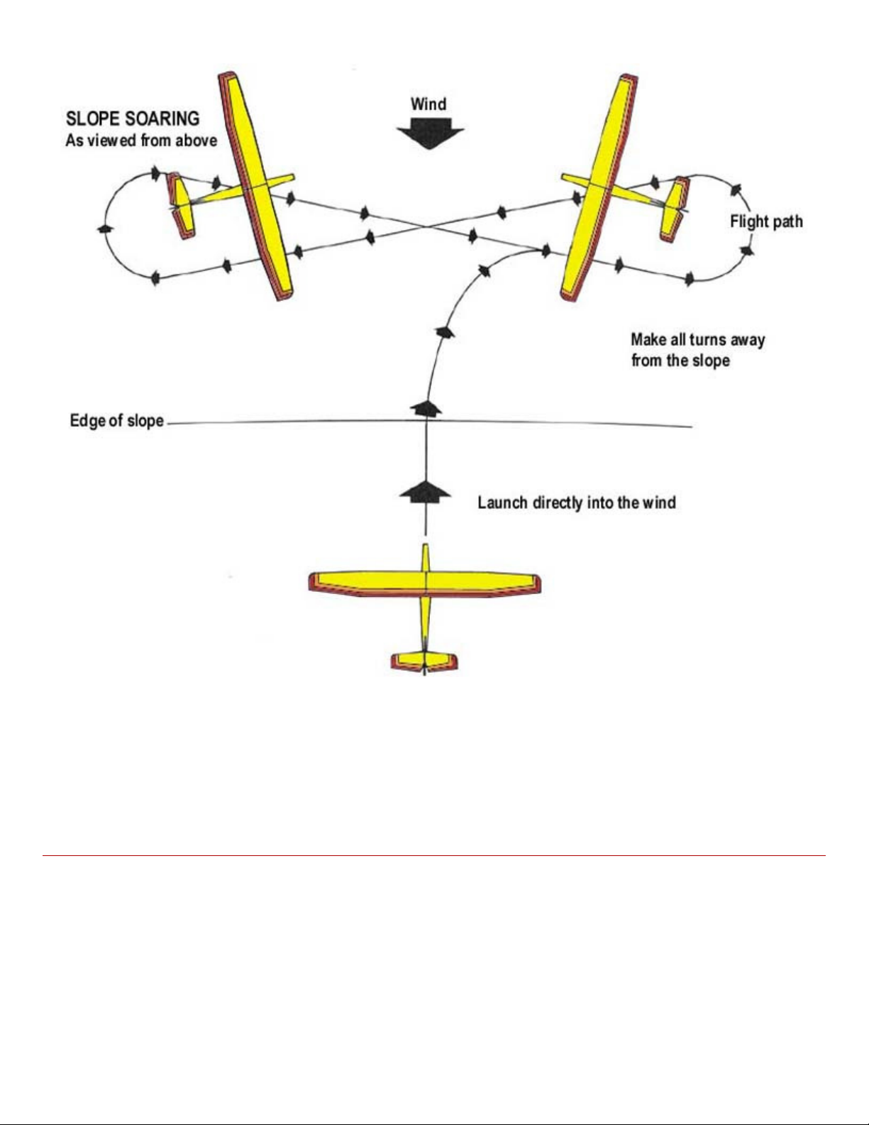
Launch the sailplane out over the crest of the hill by throwing it with the wings level and with the nose of the sailplane
pointed slightly down. Fly the sailplane parallel to the slope, and when you need to turn around, always make your turns
into the wind, away from the slope. Use smooth control movements and fly the sailplane back and forth across the slope
staying in the lift. Never turn downwind, into the slope until you decide it is time to land. When landing, make sure that you
hill. If you are too high on your landing approach, make S-turns to lose altitude or go around.
Page 27
.
If you have any technical questions or comments about this kit, or any other SIG product, please call us.
SIG MODELER'S HOTLINE
SIG MFG. CO., INC............Montezuma, Iowa 50171
-
0520
therewith.
1-800-524-7805
Weekdays, 7:00am - 4.30pm Central
© Copyright SIG Mfg. Co., Inc.
LIMIT OF LIABILITY:
In use of our products, Sig Mfg. Co.'s only obligation shall be to replace such quantity of the product proven to be defective.
User shall determine the suitability of the product for his or her intended use and shall assume all risk and liability in connection
 Loading...