

Page 1
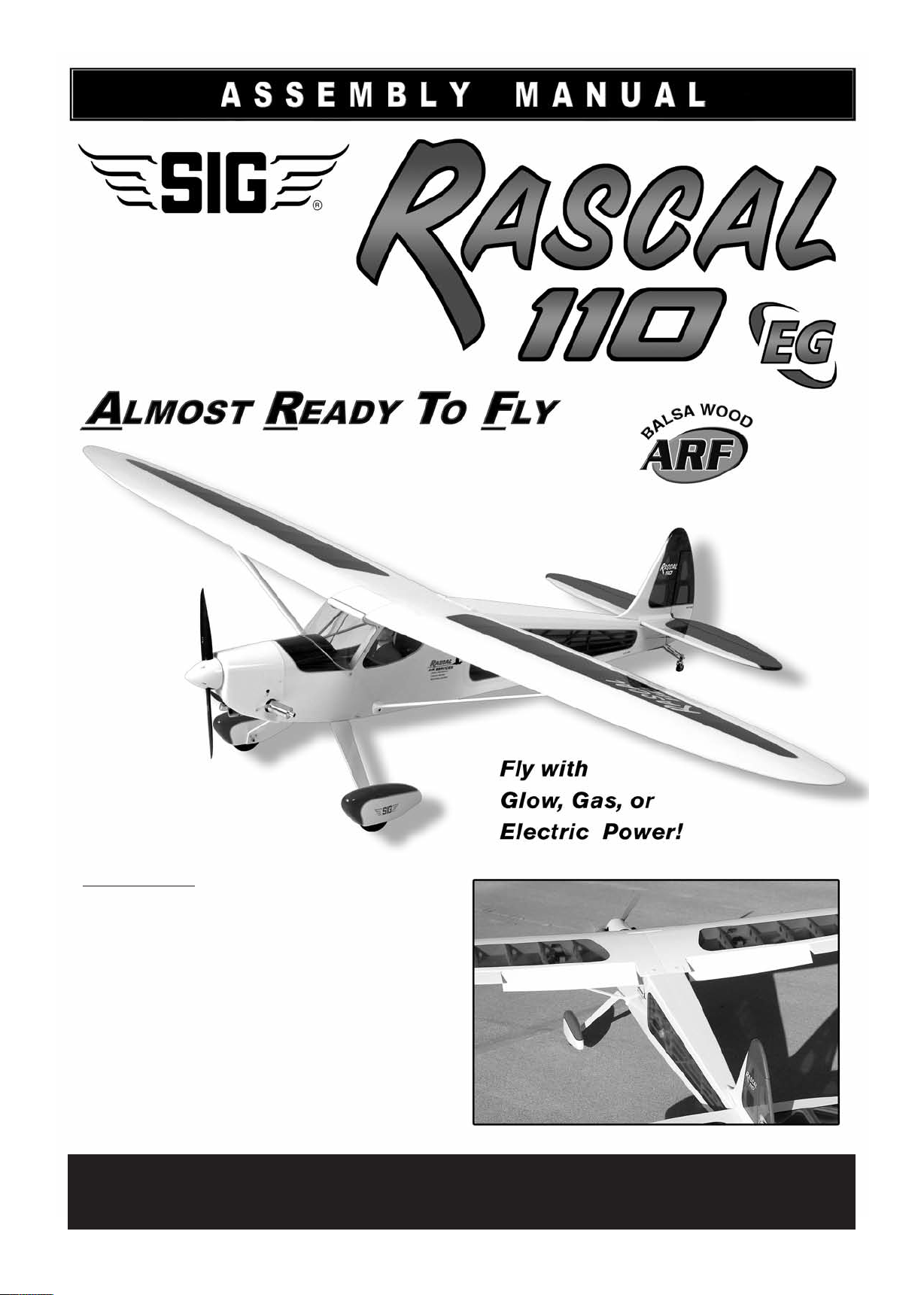
KIT NO.: SIGRC84EGVARFB - (White / Trans Blue)
SIGRC84EGVARFR - (White / Trans Red)
SPECIFICATIONS:
Wing Span: 110 in. (2794 mm)
Wing Area: 1522 sq. in. (98.2 dm2)
Length: 75.75 in. (1924 mm)
Flying Weight: 11 - 13 lbs. (4990 - 5897 g)
Wing Loading: 17 - 20 oz./sq.ft. (51 - 60 g/dm
Glow Power: 2-Stroke 1.2 - 1.5 cu. in. (20 - 25 cc)
4-Stroke 1.2 - 1.8 cu. in. (20 - 30 cc)
Gas Power: 1.2 - 1.8 cu.in. (20 - 30 cc)
Electric Power: 1600 - 2600 watt (200-270 kv) Brushless Motor;
80-120A ESC; 8S-12S Lipo Battery Pack
Radio Required: for Glow or Gas:
5-Channel with 7 Heavy-Duty Servos
Ail(2), Elev(1), Rud(1), Thro(1), Flaps(2)
for Electric:
5-Channel with 6 Heavy-Duty Servos
Ail(2), Elev(1), Rud(1), Flaps(2)
2
)
SIG MFG. CO., INC. PO Box 520 Montezuma, IA 50171-0520
www.sigmfg.com
© Copyright 2014, SIG Mfg. Co., Inc.
Page 2
RASCAL 110 EG ARF ASSEMBLY MANUAL
INTRODUCTION:
Congratulations on your purchase of the RASCAL 110 EG ARF.
We predict that you are going to fall in love with this airplane.
Take-offs and landings are spectacular in their smoothness, and
when it comes to what goes on in the air, the Rascal 110
is positively elegant. Exceptional streamlining and a high
performance airfoil allow the Rascal 110 to do things o
ther high
wing airplanes can't do. Slow rolls, point rolls, easy inverted
flight, Cuban 8s, etc. ... are all part of the Rascal 110's
aerobatic routine. The light wing loading of the Rascal 110
makes it a versatile workhorse. Float flying, banner or glider
tow, onboard video or camera work (several universities and the
military are using them), parachute drop, night flying with
add-on lights, and j
ust about any other load carrying task is
easy for the giant RASCAL 110. You won't find a better
behaved, more honest airplane than this superb flying machine!
The RASCAL 110 ARF can be assembled and ready for the
flight line in a few short evenings. The all-wood airframe is
CNC laser cut and factory jig built. That means the few parts
you need to glue together are guaranteed to fit "like a glove".
The airplane is expertly covered with Ultracote
®
(aka
ORACOVER®) premium covering material. The factory-painted
cowling and wheel pants are quality hand-laid fiberglass. The
functional airfoil shaped aluminum wing struts and massive
spring aluminum landing gear are also factory-painted and
ready to bolt on. The leaf-spring tailwheel assembly is
completely assembled and ready to use. The kit also includes
omplete hardware, wheels, spinner, fuel tank, and a fully
c
illustrated assembly manual that leaves nothing to the
imagination.
4-stroke glow (single or twin cylinder), gas, or electric power.
Keep in mind that the airplane has been designed to be
relatively light, producing a good flying model with a very
favorable wing loading. In addition, the design is
aerodynamically clean for a high-wing model. T
hese two factors
result in very good performance when using engines in the
suggested range. Over-powering this model is totally
unnecessary and not recommended.
GLOW ENGINE
We recommend the following sizes for the RASCAL 110.
2-Stroke - 1.20 - 1.50 cu. in. (20 - 25 cc)
4-Stroke - 1.20 - 1.80 cu. in. (20 - 30 cc)
Some glow engines that have been popular in the RASCAL 110
are: Saito 1.50 and 1
.80 single cylinder 4-stroke; O.S. 1.20
single cylinder 4-stroke; O.S. 1.20 and 1.60 twin cylinder
4-stroke;
Note: In the installation of a twin cylinder engine, the only real
issue is how to install the fiberglass cowl over the two cylinder
heads. We have made a twin cylinder installation (OS Gemini
1.60 Twin) and found the best way to deal with the cowl is to
neatly "split" it, from front to rear,
along the centerline of the
engine, creating top and bottom cowl halves. The two halves
could then be joined along the seam with small bolts. Neatly
done, this would create fairly easy engine access and a very
realistic look.
GAS ENGINE
We recommend the following sizes for the RASCAL 110.
1.20 - 1.80 cu.in. (20 - 30 cc)
Some gasoline engines that have been popular in the RASCAL
110 are: Syssa 30 (30 c
c); Zenoah G26 (26 cc); DLE 30
(30 cc); FPE 1.3 (21 cc); Evolution 26GT (26 cc)
GLOW & GAS ENGINE USERS
Because of the wide variety of engines that can (and have)
been used in the RASCAL 110, it is virtually impossible for us
to cover every installation, and answer every possible question,
in detail. Two-stroke, four-stroke, and gas engines often use
different styles of engine mounts; different types and sizes of
fuel tanks; and have different pushrod requirements. Some
engines come with a mount, especially g
as engines. Rather
than put engine mounts and fuel tanks in this kit that most of
you won't be able to use, we are leaving it up to you to supply
your own engine mounts and fuel tanks. There is a basic wire
pushrod included, with a nylon sleeve, pushrod connector for
one end, and metal clevis for the other end. This type pushrod
will for many engine throttle hookups (but not all - you may need
to acquire other after market parts).
Assembly of the Rascal 110 is fast and simple when following
the detailed instructions in this manual. We urge you to read
this assembly manual completely before assembly. Familiarize
yourself with the parts and the assembly sequences. The
successful assembly and flying of this airplane is your
esponsibility. If you deviate from these instructions, you may
r
wind-up with problems later on.
We hope you will enjoy this legendary R/C model. We’re
confident you will love the way it flies! Let’s get started!
ADDITIONAL ITEMS YOU WILL NEED TO PURCHASE
In addition to this kit, you will need the following items to
complete your RASCAL 110 and make it flyable.
POWER SYSTEM
T
he sky is the limit on choosing a powerplant for this versatile
airplane. The RASCAL 110 flies beautifully with 2-stroke glow,
ELECTRIC POWER SYSTEM
For electric power we recommend a
1600-2600 watt (200-270kv) Brushless Outrunner Motor
80-120 amp high-voltage electronic speed control (ESC)
8s to 12s 5000 mAh Lithium-Polymer Battery Pack (Lipo)
Suitable motors in this range that have been used in the Rascal
110 are sometimes referred to as "120" or "160" equivalent
motors. Actual measurements we
with the first 63
being the actual case diameter in millimeters.
re 6332-230
and 6364-245,
The second two digits refer to the motor armature or the case
length in mm, while the last three digits are the kv rating of the
motor.
MOTOR MOUNT: A laser-cut plywood adjustable motor mount
is included in this kit. It should work perfectly for any suitable
brushless outrunner motor which has an "X" or "cross" motor
mount plate on the back.
2
Page 3
PROPELLER: Brushless motors of this size typically use
propellers from 16 to 20 inch diameter. However, with electric
powered models, there are many factors that have a bearing on
what propeller to use. The best place to start answering the
question is in the instructions that come with your motor.
Another fine source of information is one of the electric flight
calculators that are available for you to u
se free online (there is
a good one on Castle Creations web site).
Caution: You must always match your propeller size to your
motor and to the cell count of your lipo battery pack, to avoid
drawing too many amps and damaging your ESC or motor.
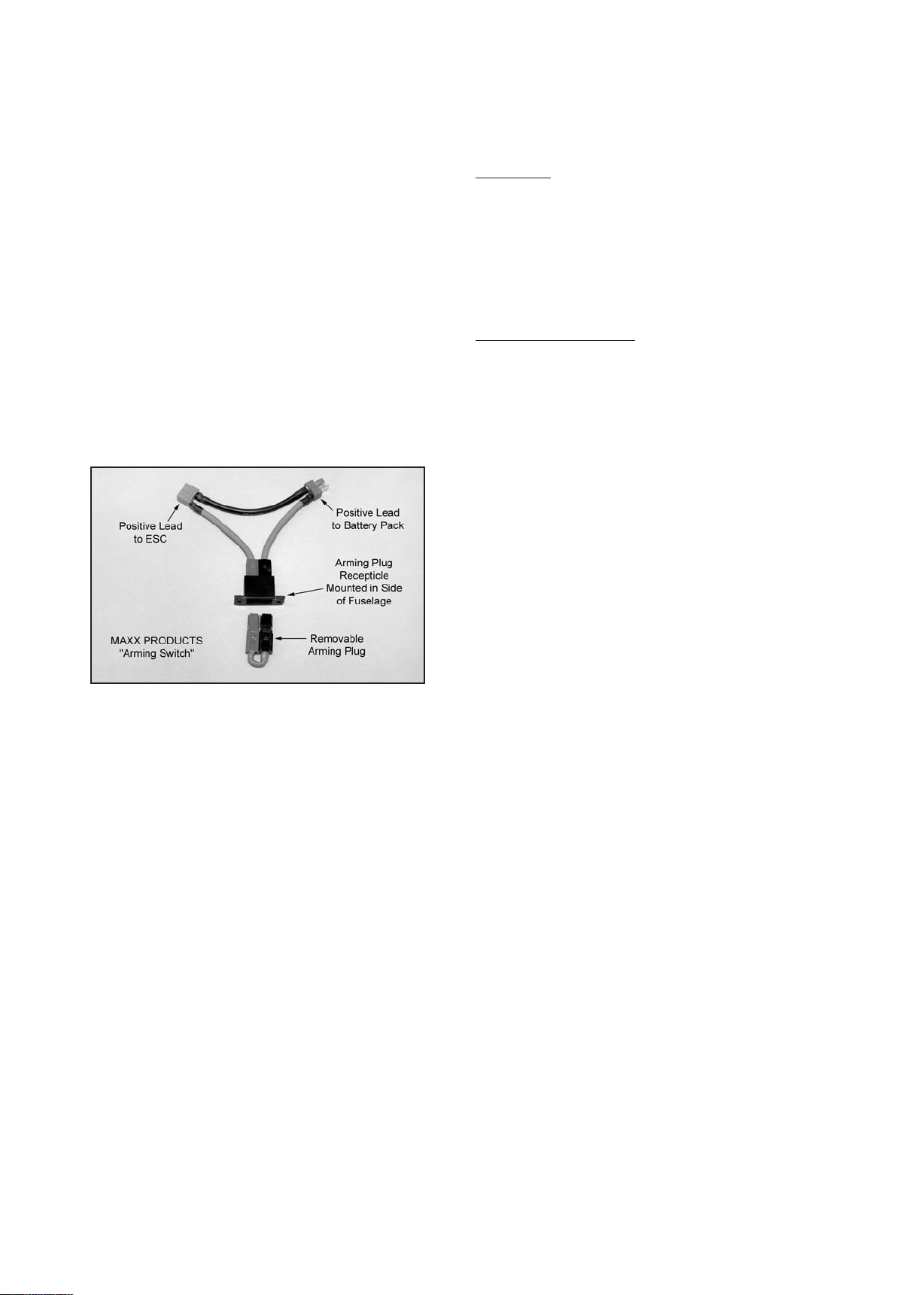
ARMING SWITCH: We strongly recommend the use of an
arming switch (not supplied) for your motor system. An arming
switch mounts in the side of your airplane and it d
isconnects the
positive wire between the battery pack to the ESC. With the
arming plug out the motor cannot start up. The battery pack can
be loaded into the airplane and plugged into the system before
going to the flight line. Once you're on the flight line with the
radio on, ready for takeoff, you "arm" the system by plugging in
the arming plug, completing the circuit. Shown is a typical
arming sw
itch harness, this one sold by Maxx Products
(www.maxxprod.com).
way of your own design, secure them securely in the up
position. Clear tape or covering material is a good method
because it can be removed later if you change your mind.
Whatever you do, if you aren't using the flaps, make sure they
are secure and cannot move from neutral position.
CHANNELS
The RASCAL 110 requires a minimum 5-channel radio system
when using the flaps, or a 4-channel radio system without
the flaps. We highly recommend the use of a modern
programmable computer radio. Such radio systems allow you
to easily set and adjust every channel and additionally program
various flight functions to suit your individual style of flying. How
many servos you need will depend on what type of powerplant
you are using and whether or not you are using the flaps.
SERVO REQUIREMENTS
Ailerons - two (2) heavy-duty servos with at least 75 in/oz of torque
Flaps - two (2) heavy-duty servos with at least 75 in/oz of torque
Elevator - one (1) heavy-duty servo with at least 75 in/oz of torque
Rudder - one (1) heavy-duty servo with at least 75 in/oz of torque
Throttle - one (1) standard servo with 40-60 in/oz of torque
®
SERVOS FOR GLOW OR GAS ENGINE POWER
If using the flaps, you will need total of 7 servo
s - ailerons(2),
elevator(1), rudder(1), flaps(2) throttle(1).
If not using the flaps, you will need total of 5 servos ailerons(2), elevator(1), rudder(1), throttle(1).
BATTERY CHARGER
FOR SAFETY AS WELL AS PERFORMANCE, CHARGE LIPO
BATTERIES ONLY WITH A LIPO BATTERY CHARGER!
In addition to providing the critical charging profile needed to
safely charge lipo batteries, a lipo battery charger also includes
the capability of "balancing" the available voltage in the cells,
ensuring that the battery pack is a
t peak capacity at the end of
the charge cycle. This translates to better flight times and a
longer life from the battery pack.
CHECK THE INTERNET FORUMS
Since the RASCAL 110 has an almost 10 year history, there is
a wealth of good how-to information available on the internet
model airplane forums, like RC GROUPS, RC UNIVERSE, and
FLYING GIANTS on many engine installations. If you do an
internet search o
f the words "Rascal 110" and the engine
you are considering, you will most likely find good first-hand
experience from flyers who have already done that particular
installation.
RADIO SYSTEM:
DECISION TIME: FLAPS OR NO FLAPS?
Before talking about the radio system, you need to decide if you
are going to use the optional flaps. The first generation
RASCAL 110 did not have flaps. With its long wing and light
wing loading, it could be a real "floater" on landing. If your
engine idle speed was a bit too high, it didn't want to come
down! Several flyers expressed interest in having flaps, so this
new generation RASCAL 110 has been built with flaps.
Whether to use them or not is your decision. If you don't want
operating flaps for whatever reason (maybe you don't want to
buy two more servos), you can simply glue, tape, or some other
SERVOS FOR ELECTRIC MOTOR POWER
If using the flaps, you will need total of 6 servos - ailerons(2),
elevator(1), rudder(1), flaps(2).
If not using the flaps, you will need total of 4 servos ailerons(2), elevator(1), rudder(1).
SERVO CORDS N
Ailerons - two (2) 24" long servo extension.cords
one (1) standard Y-harness cord (plugged into the rx)
Flaps - two (2) 6" long servo extension cords
one (1) reversing Y-harness* cord (plugged into the rx)
Elevator - one (1) 36" long servo extension cord
Rudder - no extra cords needed
Throttle - no extra cords needed
EEDED
* We used a Maxx Products®"Miracle-Y" Reversing Y-Harness
Cord.
Some of you may prefer to wire your aileron or flap servos into
your receiver by a different method, which will change the above
list. For instance maybe you prefer to eliminate the Y-harness
and plug your flap servos directly into two different ports on their
receiver, and then link them with your programable radio. Plan
out your installation in advance and acquire the cords you will
need.
SERVO ARMS
We like to use Du-Bro
®
after-market servo output arms. These
are exceptionally strong and always seem to be the right shape
and geometry for most of our applications. Du-Bro®makes their
output arms to fit any available servos, just use the right part
number for your particular brand of servos. Because our
assembly manual model is using Hitec
®
Du-Bro
#675 set.
®
servos, we chose the
RECEIVER BATTERY PACK
Do not attempt to fly the R
ASCAL 110 with a 4-cell (4.2 volt)
nicad or nimh battery pack. That is not enough volts for an
airplane this large with as many as 7 high torque servos. The
old standard 4-cell 500-600 mAh receiver packs are intended
for 40-60 size airplanes with only 4 servos. Use a 5-cell (6.0
volt) nicad or nimh battery pack, or a 2-cell (7.4 volt) lipo
pack in your RASCAL 110 to run the receiver and servos.
Otherwise you risk a low-voltage situation that could send your
3
Page 4
radio into fail-safe and cause a crash. (Be sure to check your
receiver and servo specifications for min and max allowed
voltage when selecting a receiver battery pack - especially
if going above 6.0 volts with a lipo pack - you may need
high voltage servos to use lipo.)
We also recommend that your receiver battery pack have a
1500-2000 mAh capacity. Be sure you have a charger capable
of properly charging these larger battery packs.
No radio equipment is supplied in this kit. Heavy-duty servos,
extension cords of various lengths, and Y-harness cords are all
available separately from your radio manufacturer. Check their
website, or see your local hobby shop for more information.
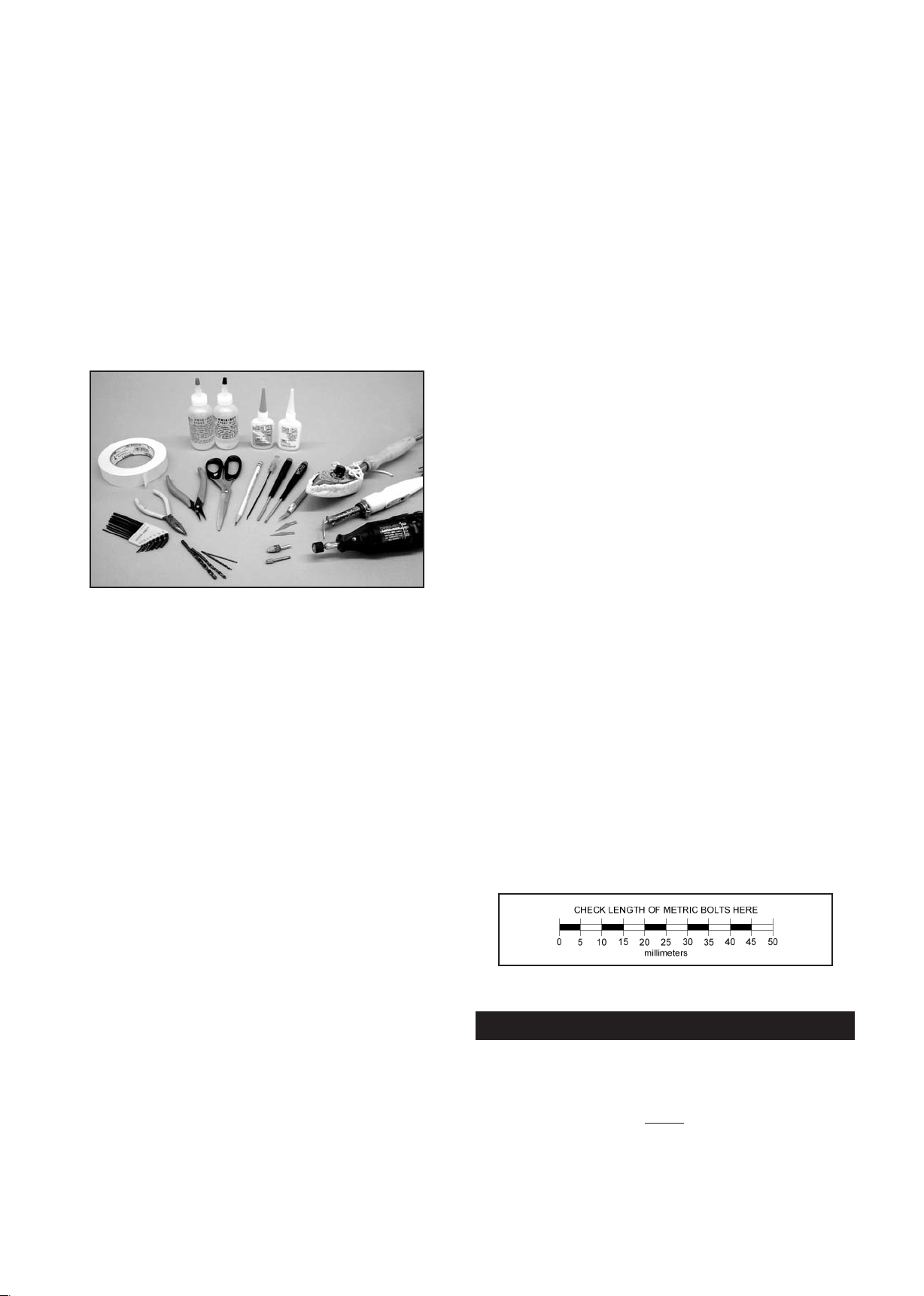
REQUIRED TOOLS
For proper assembly, we suggest you have the following tools
and materials available:
A selection of glues - S
IG Thin, Medium, & Thick CA Glue
CA Accelerator, CA Debonder
SIG Kwik-Set 5-Minute Epoxy
Screwdriver Assortment
Pliers - Needle Nose & Flat Nose
Diagonal Wire Cutters
Small Allen Wrench Assortment
Pin Vise for Small Dia. Drill Bits
Hobby Knife with Sharp #11 Blades
Small Power Drill With Selection of Bits
®
Dremel
Tool With Selection of Sanding & Grinding Bits
Scissors
Sandpaper
Heat Iron & Trim Seal Tool
Masking Tape
Paper Towels
Alcohol and/or Acetone For Epoxy Clean-up
Threadlock Liquid (such as Loctite
®
Non-Permanent)
❑
(1) Balsa Triangle Stock
❑
(1) Right Wing Strut
❑
(1) Left Wing Strut
❑
(1) Plywood Electric Motor Mount
❑
(1) Plywood Battery Tray
❑
(2) 3-3/8" long Wire Pushrod, threaded both ends,
w/ Hex Nuts; for flaps
(2) 4" long Wire Pushrod, threaded both ends,
❑
w/ Hex Nuts; for ailerons
❑
(1) 5" long Wire Pushrod, threaded both ends,
w/ Hex Nuts; for elevator
(1) 17-3/4" long Wire Pushrod, threaded one end,
❑
w/ Hex Nut; for throttle
❑
(1)
15" long Nylon Pushrod Tube, for throttle pushrod sleeve
❑
(2) Velcro®Straps
❑
(2) 4" dia. Main Wheels
❑
(2) Plastic-coated Steel Pull-Pull Cables
❑
(4) Metal Pull-Pull Swage Tubes
(8) Magnets (removable side windows for electric power)
❑
❑
(1) Tailwheel Assembly, with Steering Arm
❑
(3) M3 x 20mm Socket-Head Bolts, for mounting tailwheel
❑
(1) Metal 3-Arm Rudder Steering Horn
(2)
❑
❑
❑
❑
❑
❑
❑
❑
❑
❑
❑
❑
❑
❑
❑
❑
❑
❑
❑
M2.8 x 15mm Screws; for mounting rudder steering horn
(2) Coil Steering Springs
(2) M6.5 x 45 mm Nylon Wing Bolts
(1) M4 x 20mm Nylon Bolt; for battery/tank tray
(4) Brass Pull-Pull Fittings; for rudder
(4) M2.7 Hex Nuts; for pull-pull fittings
(14) M2.7 Metal Clevis; for ail(4), flaps(4), rud(4), ele(2)
(1) M1.7 Metal Clevis; for throttle pushrod
(1) Pushrod Connector w/ Set Screw; for throttle pushrod
(15) Short pieces of Fuel Tubing; for clevis keepers
(5) Nylon Control Horns w/ Clamp; for ail(2), flaps(2), ele(1)
(2) Nylon Control Horns w/o Clamp; for pull-pull rudder
(12) M2 x 30mm Bolts; for control horns, ail(6), flaps(6)
(6) M2 x 20mm Bolts; for control horns, elev(3), rudder(3)
(18) M2 Hex Nuts; for control horns
(23) M2.3 x 7mm Screws; for windshield & ail./flap hatches
(6) M3 x 10mm Sheet Metal Screws, for cowling
(4) M3 x 12mm Socket-Head Bolts, for wheel pants
(12) M4 x 20mm Socket-Head Bolts, for landing gear(4),
electric motor(4), wing struts(4)
❑
(4) M4 x 25mm Socket-Head Bolts; for electric motor mount
(4) M4 Flat Washers; for electric motor mount
❑
❑
(8) M4 Lock Washers, for landing gear(4), electric motor(4)
❑
(8) M4 Blind Nuts; for electric motor & mount
(2) 4mm dia. Axles
❑
(2) Large Hex Nuts; for axles
❑
❑
(4) 4mm ID Wheels Collars w/ Set Screws; for axles
COMPLETE KIT PARTS LIST
The following is a complete list of all parts contained in this kit.
Before beginning assembly, we suggest that you take the time
to inventory the parts in your kit. Use the check-off boxes ❑
provided in front of each part description.
(1) Fuselage
❑
❑
(1) Right Wing w/ Aileron & Flap, hinges not glued
(1) Left Wing w/ Aileron & Flap, hinges not glued
❑
(1) Stabilizer & Elevator, hinges not glued
❑
❑
(1) Fin & Rudder, hinges not glued
❑
(1) Fiberglass Cowling
(1) Right Plastic Side Window
❑
(1) Left Plastic Side Window
❑
(1) Plastic Windshield
❑
(1) Aluminum Main Landing Gear
❑
(1) Right Fiberglass Wheel Pant
❑
(1) Left Fiberglass Wheel Pant
❑
(1) Aluminum Tube Wing Joiner
❑
COVERING MATERIAL
Your RASCAL 110 is covered with Oracover®, a premium
quality covering made in Germany, and sold in the U.S. by
Hanger-9 as Ultracote
Oracover®#10 White (Ultracote®#HANU870)
Oracover®#29 Transparent Red (Ultracote®#HANU950)
®
Oracover
#59 Transparent Blue (Ultracote®#HANU954)
4
®
.
Colors
and
or
Page 5
If sometime in the future you need replacement covering or
matching paint for repairs, they are available from your local
hobby dealer or online from Hanger-9.
How To Tighten Loose Covering
After you open your RASCAL 110 and take all the covered parts
out of their plastic bags, the covering may begin to wrinkle. This
is not unusual and is no cause for alarm.
Your airplane was built and covered in a part
of the world, which
has relatively high humidity and therefore, the wood was likely
carrying a fair amount of moisture. When exposed to drier air,
the wood typically loses this moisture, dimensionally "shrinking"
in the process. In turn, this may cause some wrinkles.
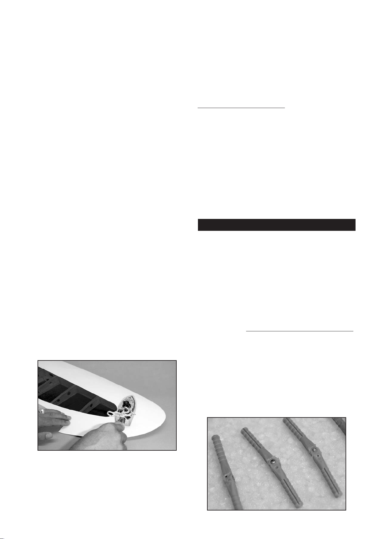
However, wrinkles are easy to remove by just using a hobby
type heat iron. Caution: Trying to remove the wrinkles by
hastily going ove
r them with a heat gun can lead to more
problems. You should take your time to carefully go over the
entire model with a covering iron, as we will describe.
We suggest using a model airplane covering iron for this
process. Cover the iron's shoe with a thin cotton cloth, such as
an old t-shirt, to prevent scratching the covering as you work.
the wrinkle for a few seconds, then remove. Repeat until the
covering is tight with no wrinkles.
If wrinkles ke
ep coming back on the tail surfaces, you may need
to "ventilate" the areas between the ribs. Otherwise the air that
is sealed in those relatively small areas will expand when the
heat is applied and actually cause the covering to stretch
instead of shrink. Use a pin to poke a tiny hole in the covering
between each rib, on the bottom of the part. That will let the
expanding air escape and the cove
Caution When Using Heat Guns:
ring to shrink properly.
You can also use a hobbytype heat gun to shrink the covering, but you must be careful
around seams or color joints. Getting too much heat on the
seams may cause them to "creep" or come loose. You must
also be careful when using a heat gun when working around the
windshield and side windows - heat will distort the clear plastic
material.
Recommended Temperatures:
To adhere the covering - 220
O
F - 250OF (104OC - 121OC)
To shrink the covering - 300OF - 320OF (149OC - 160OC)
__________________________________________________
After covering your iron, the next step is to set the iron t
correct temperature. This is critical for achieving a good result!
The iron should be set to about 220
O
F - 250OF (104OC - 121OC)
o the
as measured on the bottom of the iron using a thermometer.
This is the recommended temperature for adhering the
covering.
If you do not have a thermometer, you can find the correct
temperature by trial and error. Set your iron to a medium
setting. Glide the iron over some of the covering that is over
solid wood, such as the sheeted wing center section. Observe
the covering to see if any bubbles appear. If bubbles appear,
the covering is getting too hot! Turn down the temperature of
the iron. If no bubbles appear, turn up the heat slightly and
repeat the test. Keep adjusting until you "zero in" on the correct
temperature. Find the temperature that will get t
he covering to
stick down without forming bubbles or causing the seams to pull
away.
Once your iron is set to the correct temperature, go over the
entire framework of the airplane, making sure that the covering
is securely bonded to the structure everywhere the covering
comes in contact with the wood underneath. This takes some
time, but is worth the effort.
NOTE: In this manual, any references to right or left, refer to
your right or left as if you were seated in the cockpit of the
airplane.
WING ASSEMBLY
The wings are designed as a 2-piece system, with separate
right and left wing panels joined by an aluminum tube wing
joiner. Due to the high strength o
panels do not need to be permanently glued together. Gluing
them permanently together is optional - your call. The obvious
benefit to leaving the wing panels separate is the fact that they
can be easily transported or stored. To help protect your wings
from unnecessary damage during the following steps, we
recommend that you cover your work surface with an old
anket or piece of soft cell foam.
bl
HINGING THE AILERONS & FLAPS
As received in the kit, the wing panels have the ailerons and flaps
hinged in place, but the hinges have not been permanently glued.
Gluing the hinges will be the very first step. Use a slow setting
glue that will give you plenty of time to work the hinges into place.
If using epoxy we recommend using a slower setting time such as
30 min epoxy or longer. Traditional yellow or white water-based
wood glue is another good choice for installing these hinges.
f the wing joiner tube, the wing
After you have all the covering secured onto t
turn the temperature of the iron up to approximately 300
he solid areas,
O
F 320OF (149OC - 160OC). This is the correct temperature for
shrinking the covering material.
Use the iron to tighten up any wrinkles in the "open" areas of the
model (no wood underneath the covering). Glide the iron over
❑ 1) Remove the aileron and flap from the wing panel and
then pull all of the hinges out of off their holes.
a) Spread a little dab of petroleum jelly or lithium grease
on the pivot point of each hinge. Work it into the rivet
and hinge area to prevent glue from seeping into the
hinge and locking it up.
5
Page 6
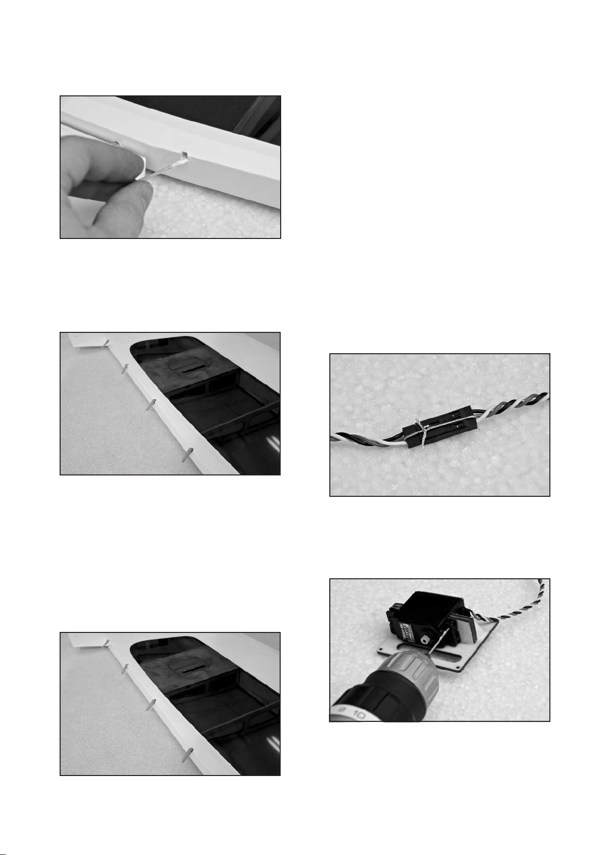
b) Use a toothpick and apply a liberal amount of glue to the
inside of the hinge holes on the back of the wing. Make
sure the glue fully coats the inside of the holes. We
suggest working with one control surface at a time.
c) Now use a toothpick to spread a thin coat of glue in the
grooves of the hinge itself (just one side of the hinge).
Then insert the hinge into the hole in the wing until the
center o
this for each hinge for that control surface. Flex the
hinges down 90
f the hinge is up to the hinge line of the wing. Do
O
to ensure that the hinges are all in line
and do not bind when the control surface is deflected.
INSTALLING THE AILERON & FLAP SERVOS
For the following steps you will need:
(1) Right Wing Panel
(1) Left Wing Panel
(16) M2.3 x 7mm Screws for servo hatches
(4) Servos with Mounting Screws
(2) 24" Servo Extension Cords for ailerons
(2) 12" Servo Extension Cords for flaps
(1) Dual Servo Y-Harness for ailerons
(1) Reversing Dual Servo Y-Harness for flaps
(not furnished)
(not furnished)
(not furnished)
(not furnished)
(not furnished)
It will be helpful to have your radio system charged and ready
to use. It is a good idea to test and center your servos before
installation to ensure everything is working and won’t have to be
removed right away for service.
❑ 2) Both aileron servos need a 24" extension cord in order
to exit at the center of the wing. The standard dual servo Y-harness will be plugged into the receiver for the ailerons. When the
wing is put on the airplane, the aileron extension cords are
plugged into the Y-harness. Prepare the servos for mounting by
installing the rubber grommets and eyelets (
supplied with your
radio system) in each servo. Using your radio, confirm that the
servos are centered before proceeding.
a) Attach the extension cords to the aileron servos.
Secure the plugs together with either string (as
shown), tape, or heat-shrink tubing. This will ensure
your servos do not come unplugged in flight.
d) Once the glue from on the hinges has dried, prepare
some more glue and using a toothpick again coat the
inside of the holes on the control surface you are
working with. Be s
ure to apply a liberal amount of glue
on the inside of each of the holes. Carefully line up all
the hinges with the holes and push the control surface
up to the hinge point. Be sure to watch for excess glue
that might seep out onto the hinge point. Clean this off
right away so it does not bind up the hinge. Flex the
control surface up and down to make sure all the hinges
are lined up without b
inding. If needed use some
masking tape to hold the control surface in place while
the glue cures. Let dry.
e) Repeat steps a) through d) to permanently hinge both
ailerons and both flaps to the wing panels.
b) Remove the aileron servo hatches from the bottom of
the wing. A standard s
ize heavy-duty servo will fit the
plywood mounting brackets on the hatches. Drill pilot
holes for the servo mounting screws. Then mount the
aileron servos on their hatches using the screws that
came with your servos.
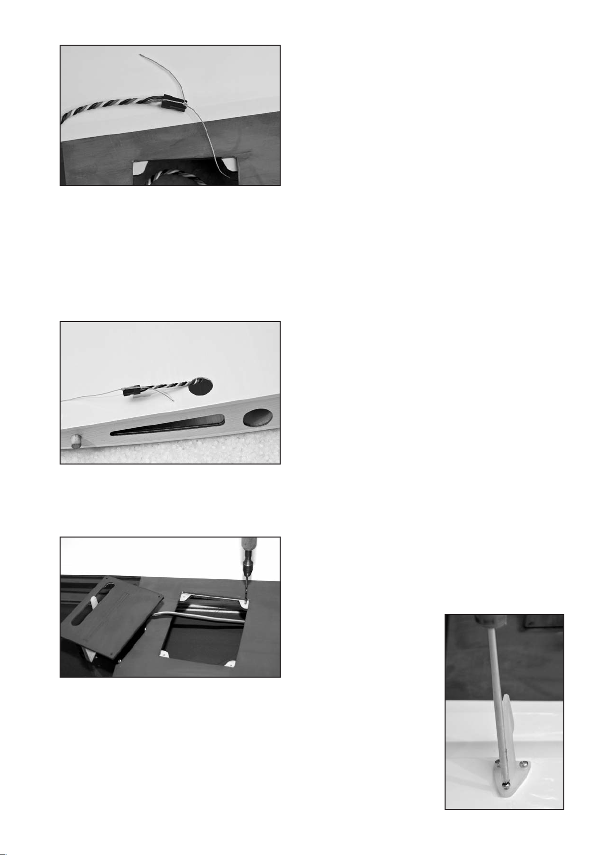
c) A string is provided in the wing panel for pulling the
aileron servo cord through the wing. Each end of the
string is taped on the outside of the wing panel.
Carefully untape t
he string at the servo opening and tie
the end of the string securely to the end of the servo
wire, as shown.
6
Page 7
d) Now untape the string at the root end of the wing panel
and begin carefully pulling the string and the aileron cord
through the wing. You will occasionally feel like the wire
has become stuck inside the wing. This is simply the
plug on the end of the servo wire hitting the side of one
of the holes in the wing ribs. Gently work the string back
and forth from both ends until the plug slips through t
hole. Sometimes the servo plug comes through all the
ribs the first time without getting hung up, and other
times it seem like it gets hung up on every rib. Be patient
and don’t try to force it.
he
the plugs together with tape or string.
b) Remove the flap servo hatches from the bottom of the
wing. Drill pilot holes for the servo mounting screws.
Then mount the flap servos on their hatches using the
screw
s that came with your servos.
c) Insert the flap servo wire and the hatch into the flap
servo bay and fish the wire out to the center section (you
shouldn't need a string to do this over the short
distance). Make sure both the flap and aileron servo
wires exit the wing panel through the round servo wire
hole in the bottom surface of the wing. It’s a good idea
to label the servo leads to easily i
aileron.
d) Mount the flap servo and hatch to the wing, using four
M2.3 x 7mm screws that are provided.
e) Repeat steps c) and d) to install the other flap servo and
hatch.
INSTALLING THE AILERON CONTROL HORNS & PUSHRODS
For the following steps you will need:
(2) Nylon Control Horns w/ Clamp
(6) M2 x 30mm Bolts for control horns
(6) M2 Hex Nuts for control horns
(2) 4" long Pushrods for ailerons
(4) Metal Clevis w/ M2.7 thread
(4) Short pieces of Fuel Tubing
dentify the flap from the
e) Mount the aileron servo and hatch to the wing. Using a
1/16 dia. drill bit, drill pilot holes in the plywood mounting
tabs in the wing panel. Use the four holes in the servo
hatch as your drilling g
are provided to mount the hatch to the wing.
f) Repeat steps c), d), and e) to install the other aileron
servo and hatch.
❑ 3) Both flap servos need a 6" extension cord in order to exit
at the center of the wing. A reversing Y-harness stays plugged
into the receiver for the flaps. When the wing is put on the
airplane, the flap extension cords are plugged into the
ess. Prepare the servos for mounting by installing the
Y-harn
rubber grommets and eyelets (supplied with your radio system)
in each servo.
a) Attach the extension cords to the flap servos and secure
uide. Four M2.3 x 7mm screws
❑ 4) At this point connect up your radio system so that you
can operate the aileron servos in order to make final
adjustments to their neutral position and overall travel.
a) Turn on the radio system and center the aileron trim
lever on the transmitter. Check to see if the aileron servo
arms are both perfectly centered on each s
the arms if necessary.
b) Determine if the servos are moving the correct direction.
Correct if needed.
c) Make sure the servo arm does not travel too far and hit
the ends of the slot in the hatch. Use the end point
adjustment feature of your transmitter to correct this in
needed.
❑ 5) Install the aileron control horns.
a) First locate the predrilled holes in the aileron. Check to
sure the covering on both sides of the aileron is
make
open over the holes. If needed run a drill bit through the
hole to open up both sides.
b) Slide three M2 x 30mm
bolts through the
control horn and then
through the bottom of
the aileron. Push or
screw them in until they
first begin to come
through on the other
side.
c) Place the nylon clamp
piece on the other side
of the aileron and feed
the bolts t
holes in the clamp.
hrough the
ervo. Adjust
7
Page 8
d) Secure the control horn and clamp in place with the M2
nuts. Be sure they are tight but do not crush the aileron
surface. Apply a small amount of blue Loctite
®
to the nut
and bolt. Repeat these steps to mount a control horn on
the other wing panel.
❑ 6) Assemble and install the aileron pushrods.
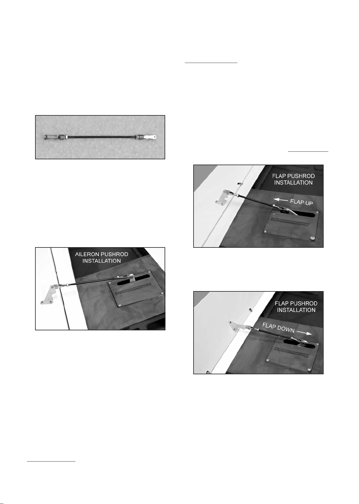
a) Pre-assemble the pushrods by first placing the small
pieces of fuel tubing over the threaded ends of the
c
levis. Screw a clevis onto both ends of the wire
pushrods. Screw the clevis on until it is centered on the
threaded portion of the pushrod. This will allow for equal
adjustment either way in the next step.
flap servo. In other words the arms for both flap servos would
be on the right (or left) side of the airplane, instead of mirror
image like the aileron servos always are. To do this on the
RASCAL 110, you would need to also flip one o
f the flap servo
hatches, and adjust the control horn location.
Alternate Method #2:
You can eliminate the need for any
Y-harness if you have an extra channel available on your
computer radio and the two available channels can be "mixed".
Plug each flap servo into separate channels, and then program
them to move in the same direction.
❑ 8) Install the nylon control horns for the flaps the same way
you did the aileron control horns in step 5.
b) Attach one end of the pushrod to the aileron servo arm.
Check that the aileron and the aileron servo are both in
neutral position, and then adjust the overall length of the
pushrod until t
he other end of the pushrod can be
attached to the control horn.
c) When finished adjusting the length of the pushrod,
tighten the M2 Hex Nut up against the back of each
clevis. To insure that the metal clevis can’t open up and
come loose from the control horn, slide the short piece
of fuel tubing over the arms of the clevis. Repeat these
steps for the other aileron pushrod.
❑ 9) At this point connect up your radio system s
o that you
can operate the flap servos. Make sure your transmitter's flap
control (knob or switch) is set to the "flap up" position, and then
turn on the radio system. The correct position for both flap
servo arms when in the flap up position is for the arms to be
angled back towards the wing trailing edge approximately 45
Reposition your flap servo arms if necessary.
With the transmitter set to the "flap down" position, the servo
arms should both pull towards the wing leading edge. If your
down flap motion moves the servo arms towards the flaps
instead of towards the wing leading edge, then you need to
reverse the direction of the flap channel in your transmitter.
O
.
❑ 7) This is a good t
ime to refer ahead to the section of this
manual titled CONTROL SURFACE TRAVEL and make final
adjustments to the operation of the ailerons.
INSTALLING THE FLAP CONTROL HORNS & PUSHRODS
For the following steps you will need:
(2) Nylon Control Horns w/ Clamp
(6) M2 x 30mm Bolts for control horns
(6) M2 Hex Nuts for control horns
(2) 3-3/8" long Pushrods for flaps
(4) Metal Clevis w/ M2.7 thread
(4) Short pieces of Fuel Tubing
NOTE: Unlike the ailerons, the flap servos both need to travel
in the same direction. The way we achieved this in our airplane
was to use a "reversing" Y-harness to operate both servos in the
same direction off of just one receiver port or channel. That is
the method described in this manual. However, there are other
options that can be used to operate flaps.
Alternate Method #1:
You could use a standard Y-harness (more
readily available than the reversing type) by simply flipping one
of the flap servos over to face the same direction as the other
Activate the transmitter flap control several times t
o make sure
the flap servo arms are in the correct position and the flap
servos are both traveling together in the right direction. If all is
correct, put the flaps servos in the full up position (servo arms
O
towards the trailing edge) and turn the radio off.
45
❑ 10) Assemble and install the flap pushrods like you did the
aileron pushrods in step 6.
❑ 11) This is a good time to refer ahead to the section o
manual titled CONTROL SURFACE TRAVEL and make final
adjustments to the operation of the flaps.
The wings of your RASCAL 110 are now complete and ready to
use. Set them aside for now.
8
f this
Page 9
FUSELAGE ASSEMBLY
TAIL SURFACE & TAILWHEEL INSTALLATION
In this section the tail surfaces will be mounted on the fuselage.
The elevator and rudder servos will also be installed. Because
of the size of the airplane, it is much easier to take care of these
steps now, before adding the main landing gear.
For the following steps you will need:
(1) Stabilizer & Elevator assembly
(1) Fin & Rudder assembly
(1) Nylon Control Horn w
(2) Nylon Control Horns without Clamp
(6) M2 x 30mm Bolts for control horns
(6) M2 Hex Nuts for control horns
(1) 5" long Pushrod for elevator
(4) Brass Pull-Pull Fittings
(6) Metal Clevis w/ M2.7 thread
(6) Short pieces of Fuel Tubing
(4) Metal Pull-Pull Swage Tubes
(2) Plastic-coated Steel Pull-Pull Cables
(1) Tailwheel Assembly
(3) M3 x 20mm Socket-Head Bolts
(1) 3-Arm Rudder Horn
(2) M2.8 x 15mm Screws
(2) Coil Steering Springs
(2) Servos with Mounting Screws (not furnished)
(1) 36" Servo Extension Cord for elevator (not furnished)
ith Clamp
c) Use a fine line felt t
the stabilizer that will make it easy for you to realign the
stab after the glue is applied in the next step.
❑ 14) The horizontal stabilizer can now be glued permanently
onto the rear of the fuselage. We suggest using slow drying
epoxy glue for this job to allow time to position the stab
accurately and make any final adjustments that might be
needed. Apply the glue eve
of the fuselage. Also apply glue to the exposed wood on the
bottom center of the stab. Place the stab onto the fuselage,
making sure it is properly aligned in top view as well as the front
view. Use weights or pins to hold the stab in this aligned
position until the epoxy cures. Wipe away any excess epoxy
with rubbing alcohol and a soft paper towel. Allow
dry completely.
ip pen to mark some guide lines on
nly to the stab saddle at the top rear
the glue to
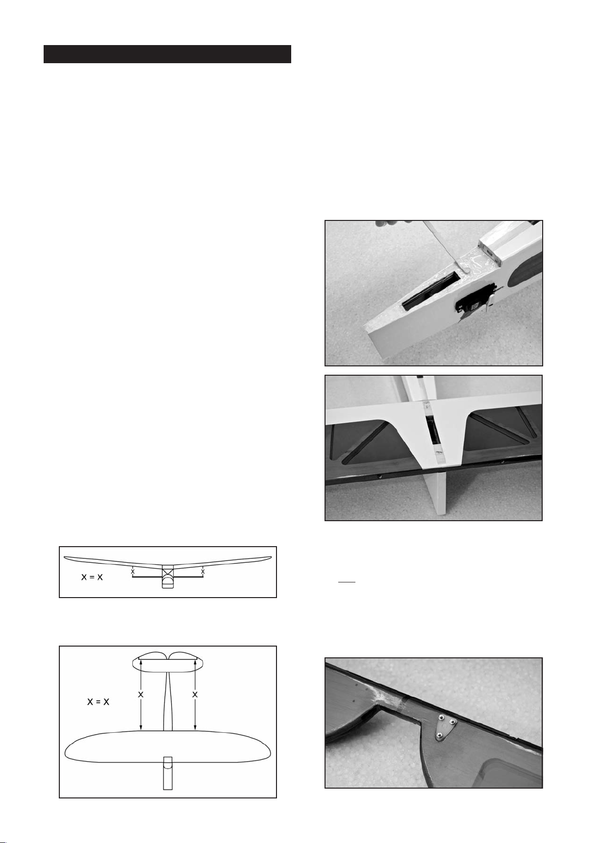
❑ 12) In preparation to gluing the stabilizer on the fuselage,
join the two wing panels together with the aluminum tube wing
joiner. Then bolt the wing in place on the fuselage with the
nylon wing bolts provided (be sure that the aileron and flap
servo wires are inside t
surface with enough space around it to easily view it from both
the front and rear.
❑ 13) Remove the elevator and hinges from the stabilizer and
elevator, and set them aside for now. Place the stabilizer onto
the fuselage, aligning it with the centerline of the fuselage. Hold
it in this position with a weight to be sure it is sitting flat on the
fuselage. Step b
the wing.
a) First view the model from directly in front. Check to see
if the stabilizer is level with the wing, without tilting one
way or the other.
b) Carefully square the stabilizer to the fuselage and
wing in the top view. This is easiest to do by taking mea-
surements from the same point on each side of the airplane.
he fuselage). Set the airplane on a flat
ack and check the alignment of the stabilizer to
❑ 15) While the glue is drying on the stabilizer it is a good time
to install the control horn on the elevator, before hinging the
elevator to the stab.
a) The elevator control horn goes on the bottom side of the
elevator. Locate the pre-drilled holes and make
right
sure they are clear all the way through the elevator.
b) Slide three M2 x 20mm bolts through the control horn
and into the bottom of the elevator. Push or screw them
in until they first begin to come through on the top side
of the elevator.
9
Page 10
c) Hold the nylon clamp piece in place on the top side of
the elevator and feed the bolts into the clamp.
d) Secure the control horn and clamp in place with the M2
nuts. Be sure they are tight but do not crush the balsa
surface. Apply a small amount of blue Loctite
®
to the nut
and bolt.
❑ 16) After the stabilizer joint is completely dry, glue the fin in
place on the fuselage.
a) Start by pulling the fin and rudder apart. Set the rudder
and hinges aside for now. Test fit the fin in place on top
of the stabilizer. Check to see that the fin sits flush and
perpendicular to the stabilizer. Check the fit of the fin's
bottom surface, where it contacts the stab and fuselage.
It should contact these surfaces from front to rear. If
necessary, trim or sand the bottom of the fin for the
best fit.
b) When satisfied with the fit, glue the fin in place using
slow drying epoxy glue. Apply a coat of glue to the
bottom of the fin and to the bottom of the vertical fin,
including the tab that fits into the top of the stab. Put a
coat of glue on the exposed wood on the stab. Press the
fin in place into the stab slot and firmly onto the stab and
fuselage.
bolts through one of the control horns and then slide the bolts
through the 3 holes in the ru
dder. Slide the other control horn
onto the bolts, and then add the three M2 hex nuts. Be sure to
tighten the nuts to securely. Do not crush the wood.
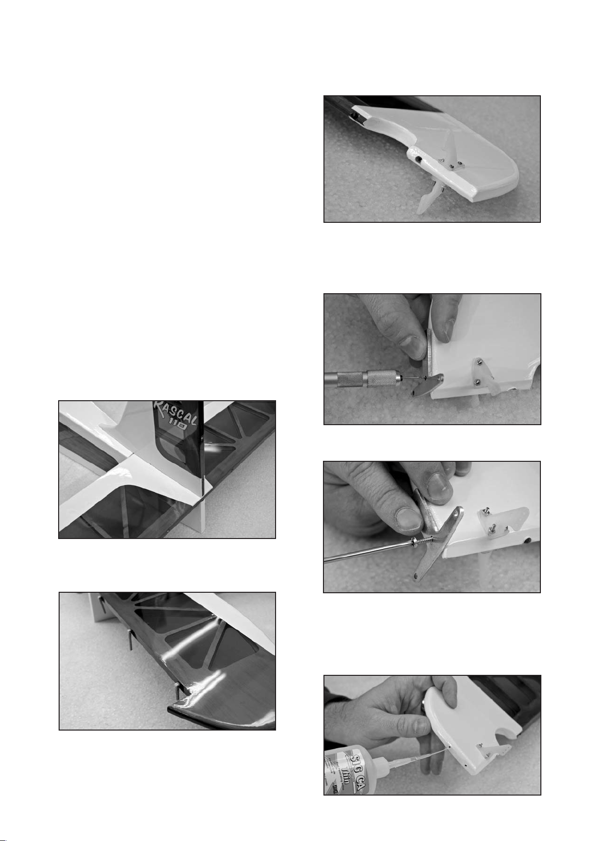
❑ 19) Mount the 3-arm Rudder Horn to the bottom of the
rudder. Locate the horn on the bottom of the rudder about 1/4"
back from the leading edge.
a) Use a 1/16" drill bit to make pilot holes in the hardwood
built into the bottom of the rudder.
c) With the fin in place, sight the model from the f
ront to
make sure the fin is absolutely 90 degrees upright to the
stab, without tilting one way or the other. If needed, use
masking tape to hold it in alignment until dry. Wipe off
any excess glue rubbing alcohol and a soft paper towel.
Let dry.
❑ 17) The elevators are now hinged to the horizontal
stabilizer. The hinging method is exactly the same as used with
the aileron hinges (back in Step 1).
b) Use t
he M2.8 x 15mm screws to mount the 3-arm
rudder horn to the rudder.
c) After you mount the horn the first time, take it back off
the rudder and reinforce the threads in the rudder with
thin CA. Carefully add a few drops of thin CA into
each hole. Let dry. This will harden the threads in the
wood. Once the CA has dried, screw the rudder
horn back in place.
8) Before hinging the rudder to the vertical stab it is best to
❑ 1
attach the control horns to the rudder. Locate the pre-drilled
holes near the bottom leading edge of the rudder and make
sure they are clean all the way through. If needed run a 1/16"
drill bit through to clean out the holes. Push three M2 x 20mm
10
Page 11
❑ 20) Hinge the rudder in place.
a) First check to make sure all of the holes for all the hinges
in the fin and in the rear of the fuselage are clear. You
may need to remove the covering from the rear of the
fuselage to open the hole for the bottom hinge. Use a
sharp razor to cut the covering free.
❑ 21) Locate the 3 holes at the bottom rear of the fuselage for
mounting the tailwheel assembly. Make sure the covering is
clear from these holes. Line the tailwheel assembly over the
mounting holes and use the M3 x 15 socket-head bolts to
secure it to the fuselage. We recommend using some blue
thread locker to ensure the bolts do not come loose.
b) Using the same method as the all the previous, first glue
the hinges into the fin and fuselage. Be sure t
hinges by laying each one over 90
O
, as shown. This will
o align the
make sure that all the hinges are in alignment.
c) Once the glue has dried, apply glue to the holes in the
rudder and then carefully slide the rudder onto the
hinges. Check for any excess epoxy leaking out around
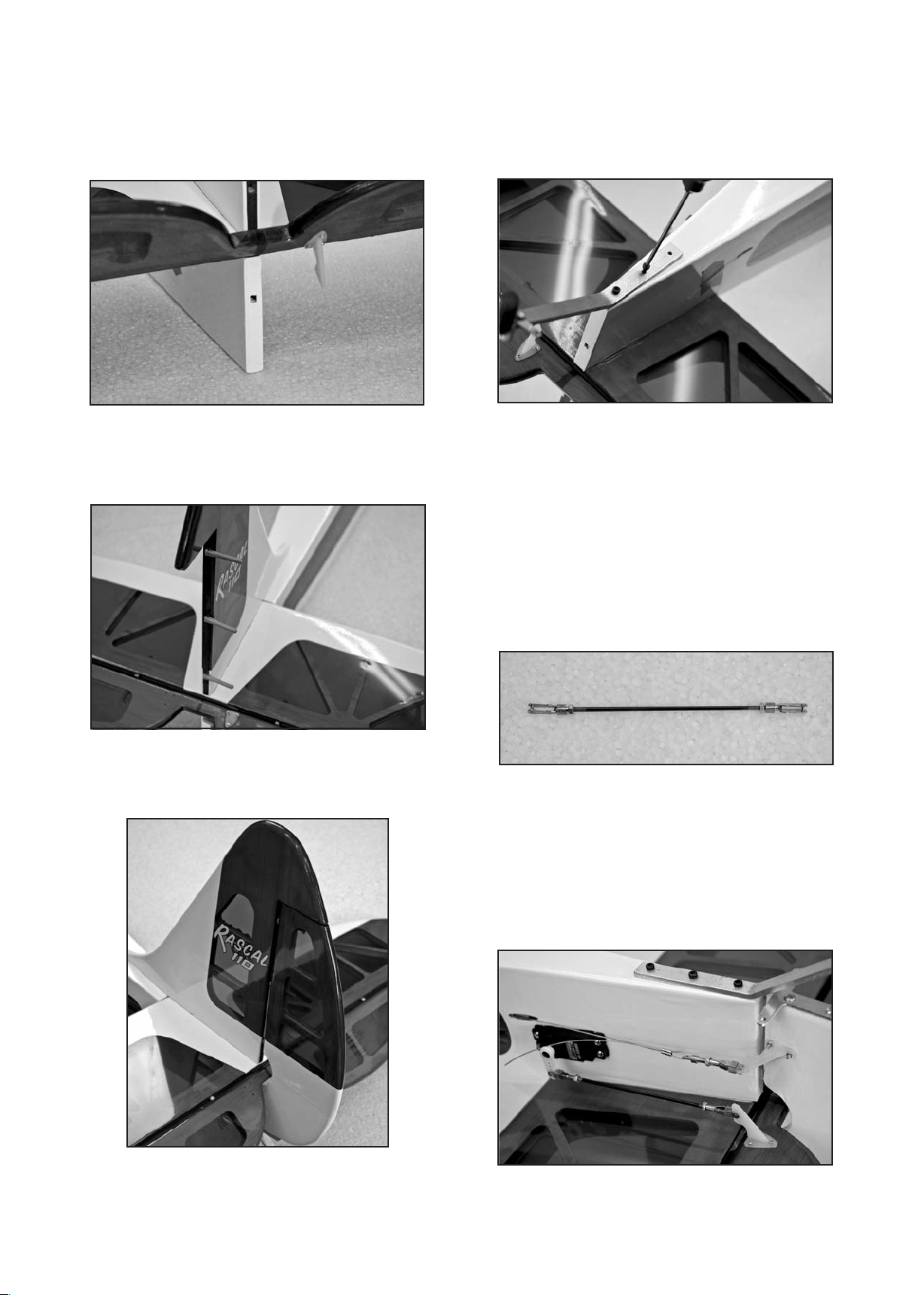
❑ 22) Install the eleva
tor servo and pushrod.
a) Start by attaching a 36" long servo extension cord to a
elevator servo. Secure the connectors together with
tape, string, or heat-shrink tubing. Insert the servo in the
open slot on the right rear side of the fuselage, while
feeding the servo cord to the middle of the fuselage.
Mount the elevator servo in place using the hardware
that came with.
b) Locate the 5" long p
ushrod for the elevator. Slide a short
piece of fuel tubing onto the shank of two of the metal
clevises. Then screw the clevises halfway onto both
ends of the pushrod.
c) Make sure the elevator servo is centered in neutral
position. Also secure the elevators at neutral, perfectly
in line with the stabilizer. Modeler's Tip: Two long flat
sticks (not supplied), one on each side of the fin and
with the ends of the sticks held together with
rudder,
small rubber bands or tape, works good for this.
the hinge points and clean it up with some alcohol and a
paper towel. Let the epoxy set, then flex the rudder to
sure the hinges are moving freely.
make
d) Attach one end of the pushrod in the outer hole of the
elevator servo arm.
e) Adjust the length of the pushrod until you can clip the
other clevis into the elevator control horn.
11
Page 12
f) When finished adjusting the length of the pushrod,
tighten the M2 Hex Nut up against the back of each
clevis. To insure that the metal clevis can’t open up and
come loose from the horn, slide the short piece of fuel
tubing over the arms of the clevis.
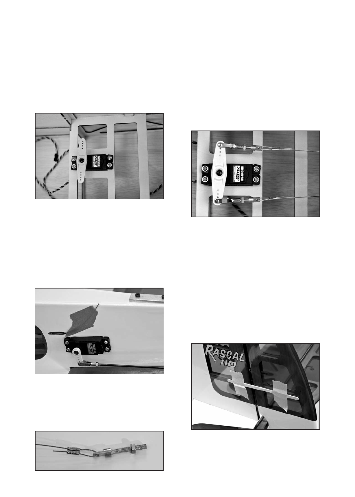
❑ 23) Install the rudder servo into the center servo slot of the
plywood tray at the back of the cabin area. The servo arm
should be towards the front of the tray. Secure the servo to the
tray using the hardware supplied with your servo. Center the
servo and install a double sided servo arm. We recommend the
®
Du-Bro
"Super Strength" servos arms, with the 1-3/4" double
arm for the rudder.
fitting, as shown. Use an ordinary
pliers to crimp the
swage tube flat around the cable to secure it in place.
b) Screw a metal clevis onto the threaded end of the
pull-pull fitting. Screw it halfway onto the threads,
leaving room for adjusting in both directions. Then clip
the clevis into the outside hole on one side of the rudder
servo control arm. NOTE: Make sure you cross the
pull-pull cables over once from the tail to the servo. O
ne
cable should go from the right side of the servo arm to
the left side of the rudder, and the other cable from the
left side of the servo to the right side of the rudder. This
gives the cables a straighter run from front to back.
c) Repeat steps a) and b) to finish the servo end of the
other rudder cable.
❑ 24) At the rear of the fuselage, just in front of the servo
cutouts, you will find two oval holes in the frame that need to
have the covering cut free. These are t
he exit holes for the
pull-pull cables. Using a razor sharp blade cut out the covering
from the oval hole on each side.
❑ 25) Locate the pull-pull cables and feed one into each hole
from the rear of the fuselage and pull them forward to the servo
tray area. Make sure they are clear of any of the support
structure inside the fuselage. Tape the loose ends of the two
cables to the rear of the fuselage t
o keep them from falling
inside.
❑ 27) Now we will finish the rudder end of the pull-pull cables.
a) First secure the rudder i
n neutral position using some
flat sticks taped along the sides of both surfaces (see
pic). Also make sure the rudder servo is also in neutral
centered position.
b) Slide a short piece of fuel tubing onto the shank of two
of metal clevises. Then screw the clevises halfway onto
the threaded end of the two remaining brass pull-pull
fittings.
c) Clip one of the clevis/pull-pull fittings into the outside
ole of each rudder control horn.
h
d) Now secure the rudder in neutral position using some
flat sticks taped along the sides of both surfaces (see
pic). Also make sure the rudder servo is also in neutral
centered position.
❑ 26) We will work on the servo ends of the pull-pull cables
first.
a) Run the end of one of the cables through a metal
pull-pull swage tube; then through the brass pull-pull
fitting; and then back through the swage tube again.
Leave about 1/4" outside the swage tube, and about 1/4"
between the swage tube and the end of the pull-pull
e) Next untape one of the pull-pull cables from the fuselage
and pull the cable out so it is tight from the rudder servo
arm. Slide the end of the cable through one of the metal
ge tubes; then through the hole in the brass pull-pull
swa
fitting; then back through the swage tube. Slide the
12
Page 13
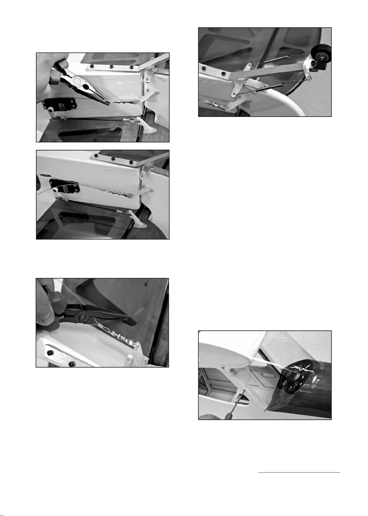
swage tube so that it is about 1/4" from the pull-pull
fitting. Make sure the cable has no slack in it and then
crimp the swage tube around the cable using a pliers.
WINDSHIELD & SIDE WINDOWS
In this section the tail surfaces will be mounted on t
The elevator and rudder servos will also be installed. Because
of the size of the airplane. it is much easier to take care of these
steps now, before adding the main landing gear.
For the following steps you will need:
(1) Clear Plastic Windshield
(7) M2.3 x 7mm Screws
(1) Right Plastic Side Window
(1) Left Plastic Side Window
(8) Magnets (only for electric power installations)
he fuselage.
f) Repeat the last step to complete the cable on the other
side of the rudder. Then clip off the excess cables with
a wire cutter, leaving about 1/4" sticking out of the swage
tube.
❑ 28) With the rudder still held at center, attach the two
steering springs.
a) Poke one end of the spring through the hole in the 3-arm
rudder horn that was attached to the bottom of the
rudder.
b) Poke the other end of the spring through the hole in the
steering arm on the tailwheel assembly.
c) Center the coil portion of the spring between the two
arms.
d) At one end of the spring, loop the tag end of the spring
wire back and twist it around itself to secure it.
e) Now go to the other end of the spring and secure it in the
same way, pulling just a very slight amount of tension on
the spring at when at neutral position.
f) Repeat this for the spring on the other side. If you have
equal tension on each side, the tailwheel will be
centered when the rudder is centered.
coil
❑ 29) Mount the windshield o
a) First place the windshield on the fuselage at the front of
the cabin. Make sure it is centered and that the sides
overlap the cabin frame with equal distance. Tape the
windshield temporarily in place.
b) Use a 1/16th drill bit to make pilots holes in the fuselage
for the seven M2.3 x 7mm mounting screws, using the
pre-drilled holes in the windshield as guides.
c) Remove the windshield f
M2.3 x 7mm screw into each hole and remove it. Put a
few drops of thin CA into each hole to harden the
threads in the wood. Let dry
.
d) Mount the windshield on the fuselage with the
M2.3 x 7mm screws.
❑ 30) Now we are going to install the plastic side windows.
There are two options for the side windows.
For Glow or Gas Power Users - If you are using a gas or glow
engine i
glue the side windows into the openings in the fuselage using a
good brand "canopy glue". Do not use CA glue for this step.
n your RASCAL we recommend that you permanently
a) Test fit the windows first. Note at the front of the window
opening that there is a slot in the fuselage structure for
n the fuselage.
rom the fuselage. Run a
13
Page 14
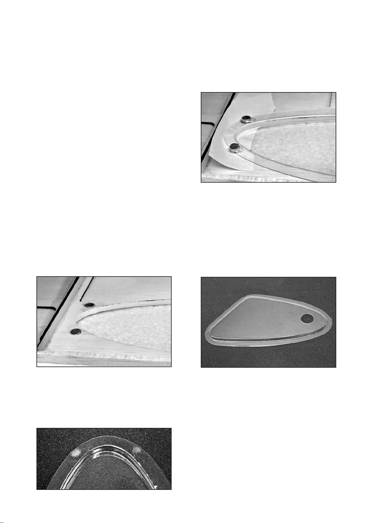
the front window flange. As you install the window, slide
the front flange into the slot. You may find that some of
the flanges around the window will need to be trimmed
a little closer in order to fit nice. A heavy-duty scissors
works good for trimming.
b) Apply a bead of canopy glue around the flange of the
window. Press the window into the cutout in the fuse
and secure it with tape. Let the glue dry overnight before
handling.
For Electric Power Users - If you are using an electric motor
in your RASCAL, we recommend that you make the side
windows removable to provide a way to load and unload your
battery pack without removing the wing. The battery pack will
go in and out of the fuselage through the open side windows.
As you stand (or kneel) in front of the airplane and look down
through the windshield, you use one hand in each side window
opening to install and plug in the battery packs. In flight, the
front of the windshield will be held in place by the front window
flange going into the slot in the fuselage. The rear of the
window will be held with magnets. The method has worked very
well for us.
a) Test fit the windows first. Note at the front of the window
opening that there is a s
lot in the fuselage structure for
the front window flange. As you install the window, slide
the front flange into the slot. You may find that some of
the flanges around the window will need to be trimmed
a little closer in order to fit nice. A heavy-duty scissors
works good for trimming.
b) Eight magnets are provided - four for each side window.
Mix up some 5-minute epoxy and glue two of the
magnets i
nto the round magnet pockets inside the
fuselage at the rear edge of the side window opening.
Make sure the magnets are pushed all the way into each
pocket. Wipe up any excess epoxy around the edges.
d) Insert the window back in fuselage. Slip a piece of wax
paper in between the window flange and the fuselage
side to insure that the window does not get glued to
the fuselage. Next, set a magnet on the flange at both
locations, testing e
ach magnet's polarity with its mating
magnet to make sure they attract each other, instead of
repel. Make sure you get the orientation of each
magnet correct. Then epoxy the two magnets onto the
window flange. Let dry.
e) Once the epoxy has dried on the first side, flip the
airplane over and repeat the process for the other side
window.
f) The final step in making removable side windows is to
provide a
way to hold onto the windows when taking
them out and putting them back in. We simply made a
small "finger grab hole" in each side window as shown.
This can be done with a sharp hobby knife or a Dremel
tool with a sanding drum bit. Make the hole large
enough to be able to slip your index finger inside the
window so you can have a good hold of it.
®
c) Once the epoxy has dried lay the fuselage on one side.
Insert the side window and mark the location of the two
magnets on the rear plastic flange of the window with
a felt tip pen. Take the w
indow back out and use
sandpaper to rough up the plastic frame over where the
magnet will be glued. This will help ensure a secure
bond to the plastic frame.
LANDING GEAR AND WHEEL PANTS
For the following s
teps you will need:
(1) Aluminum Main Landing Gear
(2) 4" dia. Main Wheels
(1) Right Fiberglass Wheel Pant
(1) Left Fiberglass Wheel Pant
(2) 4 mm dia. Threaded Axles
(2) 7.6 mm Hex Nuts; for axles
(4) 4 mm ID Wheels Collars; for axles
(4) M3 x 12mm Socket-Head Bolts
(4) M4 x 20mm Socket-Head Bolts
(4) M4 Split-Ring Lock Washers
NOTE: We suggest you use a thread locking liquid (like
Locktite
®
) on all bolts and nuts used in the assembly of the
landing gear.
14
Page 15
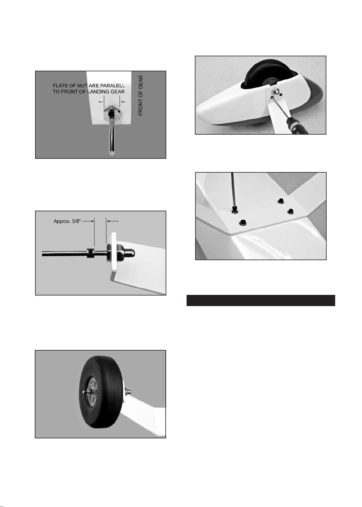
❑ 31) Install an axle in the bottom holes of the Aluminum Main
Landing Gear. Secure the axle with the 7.6mm Hex Nut. When
tightening the nut, keep the flats of the hex head of the axle (on
the side where the wheel pant will mount) parallel to the front
edge of the leg - see photo. This allows the hex head to fit
inside the notch in the wheel pants, when they are added later.
❑ 32) Slide a 4mm wheel collar o
nto the axle shaft. Leave
about a 3/8" gap between the wheel collar and the axle nut, to
provide proper spacing of the wheel in the wheel pant. Orient
the wheel collar so the set screw is pointing towards the
bottom of the landing gear. Tighten the wheel collar set screw
securely.
❑ 34) Set the wheel pant in place over the wheel, and line it up
with the mounting holes in the aluminum landing gear. Using
two M3 x 12mm socket-head bolts to fasten the wheel pant to
the gear.
❑ 35) Attach the landing gear to the bottom of the fuselage
using four M4 x 20mm Socket-Head Bolts and four M4
S
plit-Ring Lock Washers. Tighten these four mounting bolts
firmly in place.
❑ 33) Slide one of the 4" main wheels onto the axle. Make
sure that the wheel spins freely. Then slide a second wheel
nto the axle and up to the wheel. Leave just enough gap
collar o
so the wheel spins freely. Orient the wheel collar so the set
screw is pointing towards the bottom of the landing gear, and
then tighten the set screw.
Check the orientation of the landing gear to make sure you
know which way is forward. In side view, the leading edge (or
front) of the landing gear is straight, while the trailing edge (or
rear) is slightly angled. Be sure to mount the landing gear and
the wheel pants in the correct direction in the next steps!
GLOW and GAS ENGINE INSTALLATION
Skip this section if you're using an electric motor.
As mentioned in the front of this manual, due to the wide
variety and configuration of different brand glow and gas
engines, and their different engine mount and fuel tank
requirements, we have not included any engine mount or fuel
tank in this kit. Rather t
tank that most of you won't be able to use, we are leaving it up
to you to supply your own to fit your particular engine.
❑ 36) When mounting your engine keep in mind the following
design parameters.
The fuselage has been built with the correct right and down
thrust already incorporated into the firewall.
These are: 2
The firewall has been l
vertical and horizontal thrust lines, for placement of your engine
mounts. Note that the vertical thrust is off-center to the left,
allowing for the built-in right thrust. The horizontal thrust line is
offset slightly high, to allow for the down thrust. Be sure to
center your engine at these locators in order for the cowling to
fit properly. Using a stra
horizontal and vertical thrust lines to the edges of the firewall.
han put in an engine mount and fuel
O
Right Thrust
2.5ODown Thrust
aser etched with the location of the true
ight edge and sharp pencil, extend the
15
Page 16
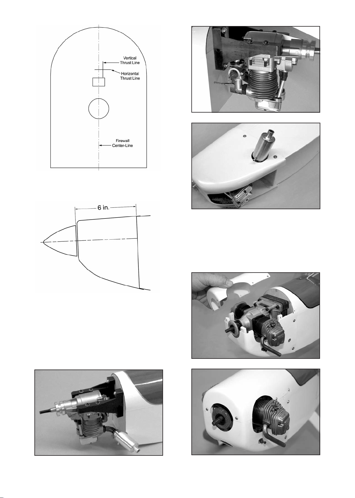
The design distance from the front of the firewall to the back of
the prop is 6 inches. Mount your engine accordingly in order for
the cowling to fit properly.
For reference, here are some photos of typical glow and gas
engine installations.
SAITO 1.50 SINGLE-CYLINDER 4-STROKE ENGINE
Engine is mounted on common universal style twin beam
engine mounts. Simple throttle hookup via flex-cable pushrod
assembly. B
stick out and for cooling.
ottom of cowling is opened up for engine head to
O.S. GEMINI 1.60 TWIN-CYLINDER 4-STROKE ENGINE
The cowling is split into two pieces along the horizontal thrust
line. Note hardwood mounting blocks epoxied along edge of
lower cowl, for top cowl mounting screws. This engine came
with an engine mount. Plywood spacers are used between the
engine mount and the firewall to prov
distance between prop washer and firewall.
ide the design 6 in.
16
Page 17
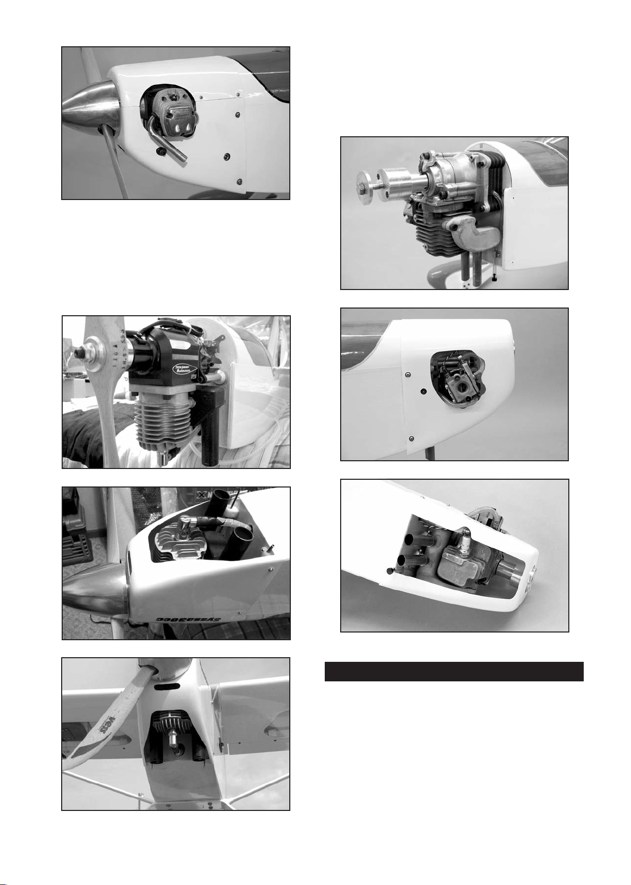
SYSSA 30cc GAS ENGINE
The SYSSA 30 is a popular gasoline engine for the RASCAL
because it does not stick out the sides of the cowling. Pillar
mount can be customized to provide the 6 in. distance from the
firewall to the prop washer. Bottom of cowling is opened up for
cylinder head and exhaust pipes.
Syssa Aircraft Performance - www.syssaaircraft.net
F.P.E. 1.3 (21cc) SINGLE-CYLINDER GAS ENGINE
This gasoline e
spacers are required to achieve the design distance of 6 in. from
the firewall to the prop washer. Carburetor sticks out of right
side of cowling. Bottom of cowling opened up for cylinder head
and good cooling.
First Place Engines - www.fpengines.com
ngine has its own integral mount. Plywood
ELECTRIC MOTOR INSTALLATION
Skip this section if your using a glow or gas engine.
This kit does include a laser-cut plywood universal m
that will work for almost all brushless motors that will likely be
used in the RASCAL 110. For that reason, we will go through
step-by-step instructions on how to use the included mount.
The mount assumes that your brushless electric motor includes
a typical "X" or "cross" style mounting plate on the back of the
motor.
For the following steps you will need:
(1) Fiberglass Cowling
(6) M3 x 10mm S
17
crews
otor mount
Page 18
(1) Plywood Electric Motor Mount
(1) Balsa Triangle Stock
(4) M4 x 25mm Socket-Head Bolts
(4) M4 x 20mm Socket-Head Bolts
(4) M4 Blind Nuts
(4) M4 Flat Washers
(4) M4 Lock Washers
(2) Velcro
®
Straps
(1) Electric Motor, ESC, Prop, Lipo Battery (not furnished)
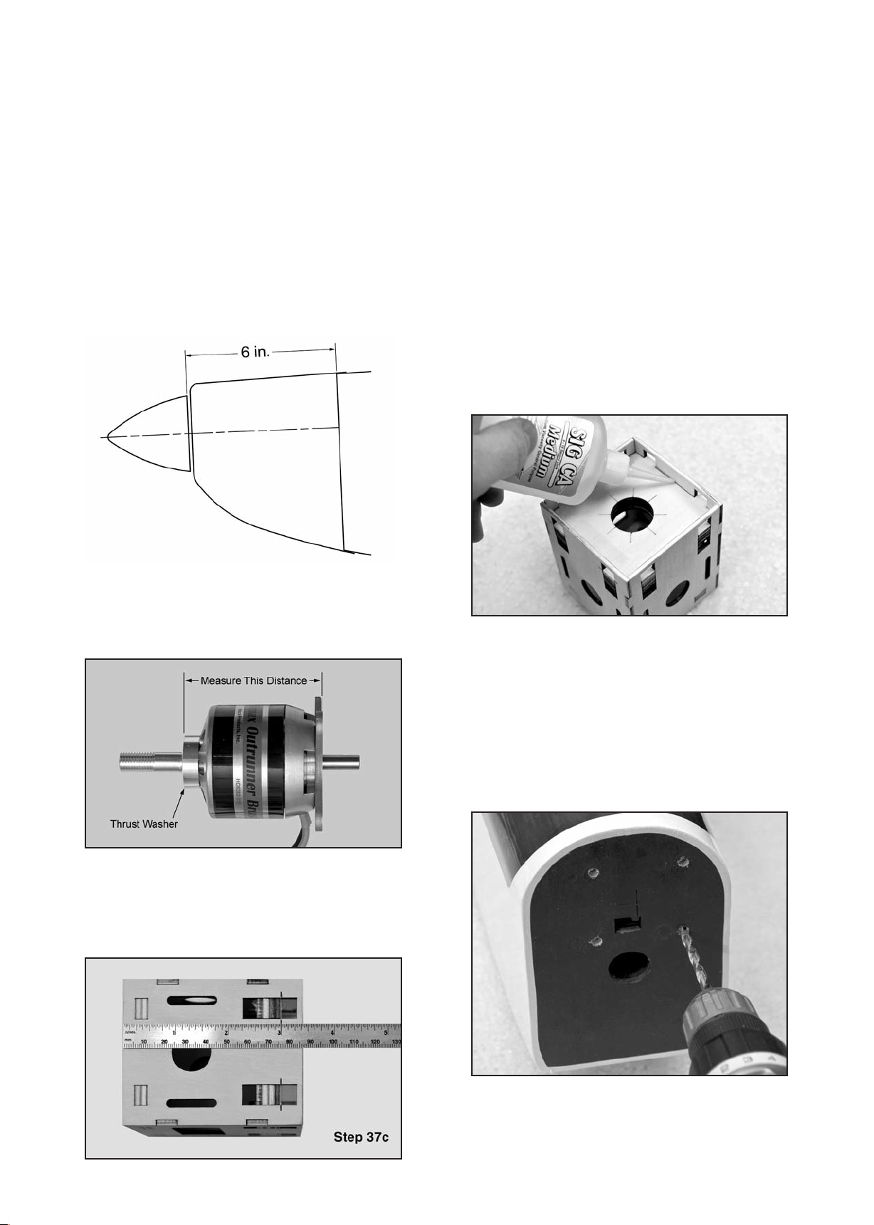
❑ 37) Note that the firewall portion of the laser-cut plywood
motor mount is adjustable fore and aft to accommodate
different length motors. In this step, we will a
djust the motor
mount for your particular electric motor. For the RASCAL 110,
we need a total distance from the back of the plywood motor
mount box to the motor’s thrust washer to end up exactly 6".
This distance allows the cowling to fit properly.
minus 3" = 3". We will set our f
irewall at 3" from the back
of the mount. Your result may be different depending on
your motor.)
c) Carefully measure and mark the distance determined in
the previous step from the back edge of the motor mount
box towards the front. Do this along side each of the
adjustment slots on both sides of the box.
d) After you have all the slots marked, move the firewall
until you have the front of the firewa
ll lined up with the
marks. Make sure you end up with the firewall straight
and square in the box. If it is not, recheck your marks
and adjust as necessary.
e) Tack glue the firewall in place. Recheck once more to
make sure that the front of the firewall is at the correct
distance from the back of the motor mount box. That
distance plus the length of your motor must equal 6".
When satisfied i
t is correct, glue the firewall securely to
the rest of the motor mount box. Make sure to soak in
some CA along all the edges.
a) Assemble your motor according to the manufacturer's
instructions. Then carefully measure the distance from
the back of the mounting plate to the front o
f the thrust
washer (the "thrust washer" is where the back of the
propeller will be located).
b) Subtract the measurement taken in the previous step a)
from 6". The result is the distance you need to locate the
front of the firewall from the back of the plywood motor
mount box. (With the motor we are using in these
photos, the motor measurement is exactly 3". So 6"
❑ 38) A set of four M4 x 25mm socket-head bolts, M4 blind
nuts, and M4 flat washers are provided for attaching the
plywood electric motor mount to the firewall. The firewall has
been laser etched with the four locations for mounting bolts.
Look closely and you will find four s
mall etched dots on the
firewall with the correct spacing to match the holes in the back
of the plywood motor mount.
a) Using a 1/16" drill pilot holes through the firewall at the
four etched locations. Then switch to a 1/4" dia. bit to
drill out the four holes to the final size to accept the blind
nuts.
b) Install the M4 blind nuts in the back of the firewall. You
will need to reach in through the f
uselage to the front of
the plane. This can be made a lot easier by inserting a
1/8" dia. dowel (7" to 8" long) through the hole from the
18
Page 19
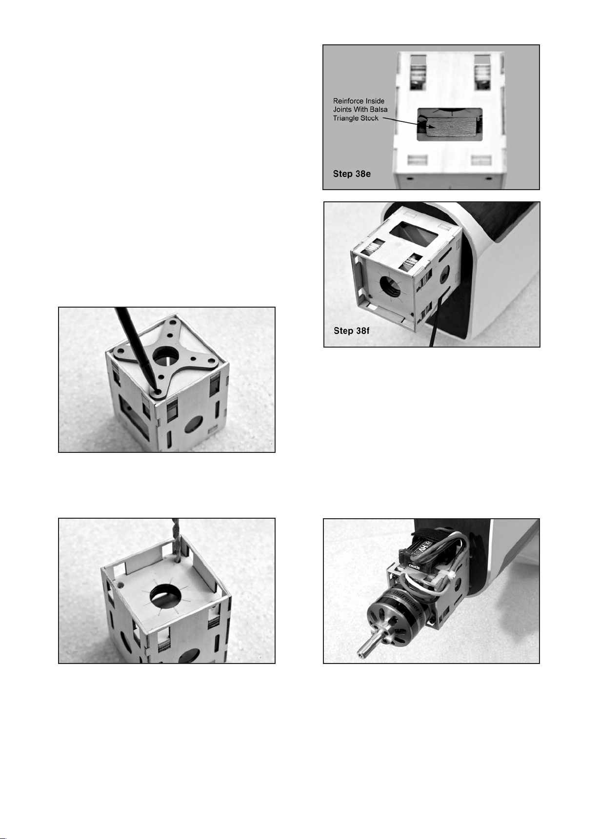
firewall side. When you can see the end of the dowel in
the fuselage, slip one of the blind nuts onto it, and then
pull the dowel back out of the hole while holding the nut
on the dowel from the inside. This will locate the blind
nut to the backside of the hole every time.
Once you have the blind nut started in the hole, hold it in
position from the inside with one hand while you remove
the dowel and start one of the M4 bolts into the blind nut
with the other hand (or enlist a helper). Tighten the bolt
to pull the blind nut into final position. Be sure to use a
flat washer under the bolt head to prevent the bolt from
sinking into the face of the firewall.
If desired, the blind mounting nuts can be permanently
adhered to the backside of the firewall by using a little
5-minute epoxy on your finger to spread the glue around
the outside edges of each blind nut. Do not get glue in
the threads of the blind nut.
c) Place the X mount, that came with your brushless motor,
on the front of the plywood motor mount. Center it using
the etched lines on the front as your guide. Mark the
locations of the four mounting holes.
d) Drill out the four holes for the X mount, first using a 1/16"
ll bit as a pilot, followed by a 1/4" bit. Then install
dia. dri
an M4 blind nut in each of the four holes, on the back
side of the firewall.
❑ 39) A set of four M4 x 20mm socket-head bolts and M4 lock
washers are provided to mount your motor to the motor mount.
Check to make sure your motor wires are not coming out the top
of the mount when the m
otor is secured or they will interfere
with the cowl. We found it best to route the wires out the
bottom of the mount. Use blue thread locker on the bolts to
ensure they do not come loose.
❑ 40) Connect the three motor wires of your Electronic Speed
Control (ESC) to the motor. Mount the ESC to the bottom or
sides of the plywood electric motor mount. Plastic cinch straps
are very handy for this, and fo
r securing loose wires to
structure. Also route the ESC's servo wire back to your
receiver and plug it in.
e) A long piece of balsa triangle stock is provided to
reinforce the motor mount. Measure, cut and glue
pieces of triangle stock in all the corner joints inside the
motor mount box. Make sure to soak in plenty of CA to
make a strong joint.
f) Mount the plywood motor m
ount onto the fuselage with
four M4 x 25 bolts and M4 flat washers. You can access
the head of the bolts through the slots in the side of the
mount using a ball-end hex wrench or driver, as shown.
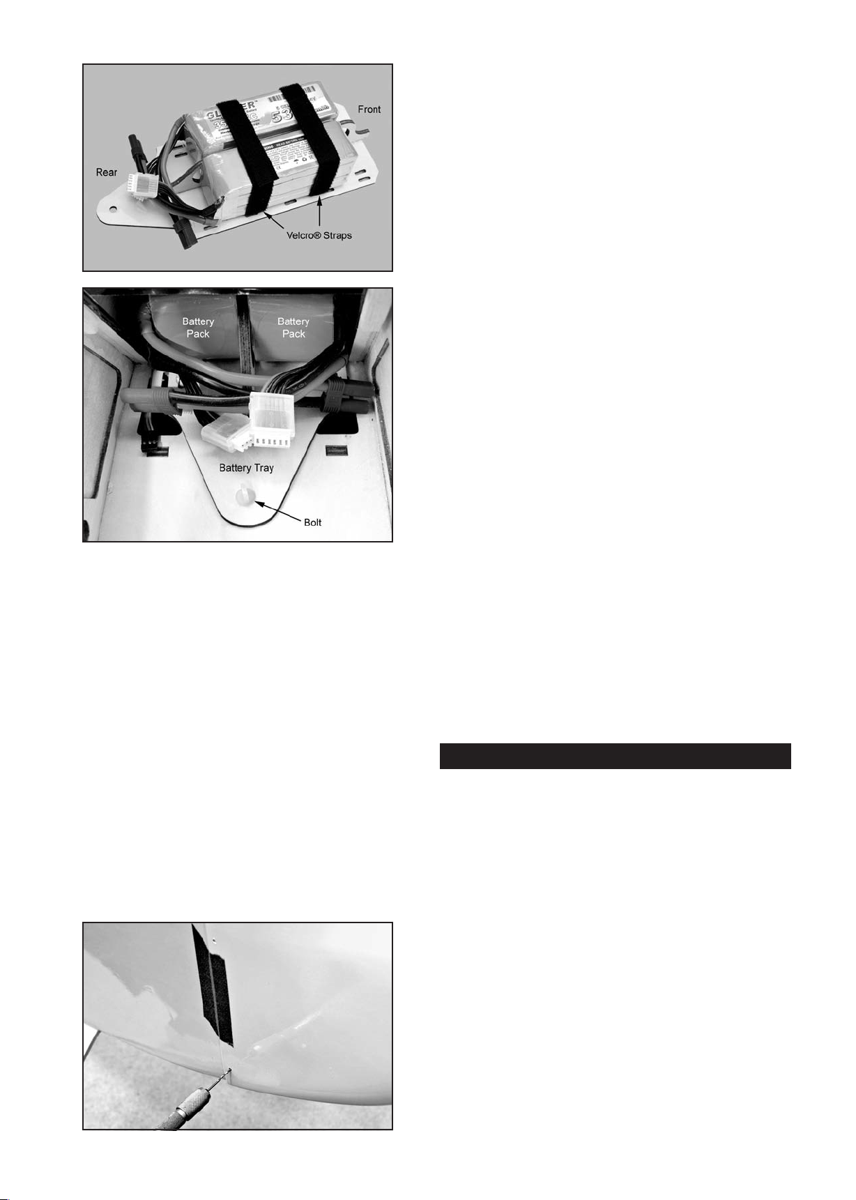
❑ 41) A laser-cut plywood removable battery tray is included
for mounting the batteries in the airplane. Use two Velcro
straps to secure your batteries to the tray and then install it into
the airplane. The tab at the front of the tray locks into a slot at
the front of the fuselage, and the rear end of the tray is held in
place with a M4 x 20mm nylon bolt. The tray with batteries will
fit into the airplane through the side windows. Optional: In
addition to the two straps, it is a good idea to use hook-&-loop
tape (not furnished) on the bottom of your battery pack and on
the top surface of the plywood battery tray, to make sure the
battery pack will not move around during aerobatics.
19
®
Page 20
c) Recheck the position of the cowling and make any
adjustments needed to get it back in position.
d) Now drill another pilot hole for the upper screw on the
other side of the cowling. Install the s
crew.
e) Repeat this process to install the two bottom cowl
mounting screws. Remove all the tape.
f) Remove the cowling from the fuselage and set it aside.
Harden the cowl mount holes in the fuselage by putting
2-3 drops of thin CA into each hole. This will harden the
threads. When you are sure the glue is dry you can
remount the cowling.
COOLING IS IMPORTANT
Regardless of what type of power system yo
u are using (glow,
gas, or electric), it is very important to make sure you have
plenty of cooling air going into and out of the cowling. While
letting cooling air into the cowling is vitally important, it is always
recommended to have more air exit area than inlet area to
create a positive air flow through the cowling. This creates an
actual suction effect, drawing the heated air out of the cowling
o that more cool air can come in. This positive air flow keeps
s
your motor running cool. Note that there is a generous sized
cutout at the bottom rear edge of the cowling for air exit.
❑ 42) Now is a good time to operate the motor and check the
direction of rotation. Do not do this with a propeller attached to
the motor! If you need to reverse the rotation, swap two of the
leads to the brushless motor and recheck the rotation.
MOUNT THE COWLING
Both glow, gas, and electric motor users resume assembly
here.
❑ 43) Mount the cowling on the fuselage with four M3 x 10mm
Screws. Notice that the h
oles for the four cowl mounting screws
are already pre-drilled in the cowling - two on each side.
a) First test fit the cowling on the fuselage. Make sure you
have adequate clearance between the front of the cowl
and the back of the propeller, and that the prop shaft is
centered in the hole. Use low tack tape to hold the
cowling in place for the next step.
b) Use a 5/64" or #45 bit to drill a pilot h
ole for the top left
cowl mounting screw. Center the drill in the hole in the
cowling and drill into the fuselage side. Install an
M3 x 10mm screw in the pilot hole - do not over-tighten
the screw.
You may choose to make some additional holes in your cowling
to ensure proper airflow. Perhaps an opening at the front of the
cowl in front of the motor or cylinder head will be needed. Or in
the case of electric m
otors you sometimes see slots in the top
of the cowl right over the motor. This will draw air in from the
top and pull it down over the motor and ESC.
®
A Dremel
Tool with an assortment of bits is without a doubt the
best tool to use for making cutout in the fiberglass cowling.
However, if you do not have access to such a tool, you can cut
the opening with a drill, a hobby knife, and a sanding block.
First first drill a series of almost touching 1/8" holes inside the
pattern lines; then use the knife to cut through the connecting
material between each hole; and finally finish the edges of the
opening with the file or a sanding block.
COMPLETE THE RADIO INSTALLATION
If using a receiver battery pack the on/off switch can be
mounted on the outside of the fuselage, using the switch
mounting hardware that came with your system. There a
holes for either a standard switch or a multi switch/charge block
already pre-cut in the fuselage sides, underneath the covering
material.
Decide where you are going to mount your receiver, and secure
it to the structure. If using a gas or glow engine be sure to wrap
the receiver in soft protective foam, held in place with tape or
rubber bands.
re
Connect all the servo leads to the appropriate channels i
receiver, including the aileron "Y" harness and the switch
connector if applicable. Test the radio system to make sure
everything works correctly. The twin cable ends of the aileron
Y-harness (or dual aileron servo extension cords if using that
method) must be accessible from the top of the cabin.. We
placed our receiver on the floor of the fuselage between the
servo tray and the battery/fuel t
ank bay.
Be sure to follow your radio manufacturer's recommendations
on routing your receiver antenna.
20
n the
Page 21
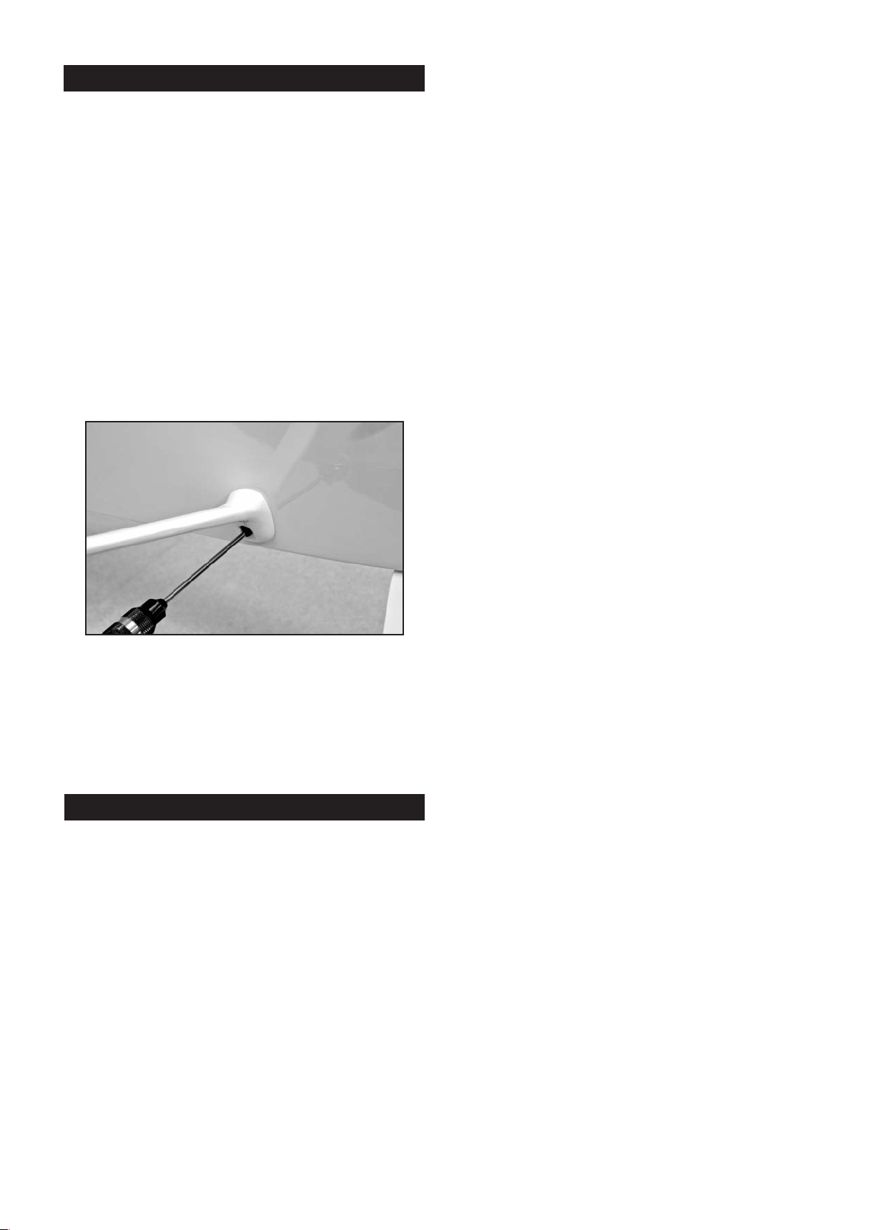
WING STRUTS
The wing struts on the RASCAL 110 are functional, and the
airplane should never be flown without the struts in place. The
struts mount to the wing and fuselage with M4 x 20mm
socket-head bolts. A metric 2.5mm ball driver is the best tool to
have for installation and removal. Do not be tempted to use an
S.A.E. 3/32" hex driver. This tool will eventually roach out the
bolt heads.
The wing struts are fa
with the appropriate blind mounting nuts that are pre-installed in
the fuselage sides and in the bottom surfaces of both wing
panels. There is a left and a right wing strut - note the airfoil
shape of each strut.
Assemble the two wing panels together, and then bolt the wing
on the fuselage with the M6.5 x 45 mm nylon wing bolts. Hold
the strut in place against t
wing panel and install the bolts, starting the threads with your
fingers. Tighten the bolts in place firmly with a hex driver.
ctory painted and already set-up to mate
he fuselage side and bottom of the
immediately next to the fuselage side. This is the location of the
main wing spars. We've flown this airplane with the C.G.
location as far back as 5" without any trouble. However, moving
the C.G. further back tends to make the elevators more
sensitive and will also accelerate the stall.
Because o
typical balancing fixture may not be practical. However, you can
get acceptably accurate results by first placing a piece of tape,
temporarily, on each side of the fuselage, just beneath the wing,
at the 4-1/2" location. Then, simply use your fingers beneath
each wing panel to pick the model up at the C.G. location.
Another method is for you and a f
the wingtips, at the main spar location.
The goal is to get the airplane to balance perfectly level at the
desired C.G. point. Level means level - not nose down or tail
down - level! If the nose hangs down, the model is nose heavy.
Likewise, if the airplane hangs tail down, it is tail heavy. If either
of these conditions exist with your model, they must be
corrected.
f its large size, balancing the RASCAL 110 using a
riend to pick the model up at
CONGRATULATIONS!
Your RASCAL 110 is completely assembled. However, it is
NOT ready for flight! There are a few very critical pre-flight
tasks we must perform before flying. These are extremely
important and should be approached with patience a
nd care.
PRE-FLIGHT
BALANCE
This may be the single most important step in preparing your
airplane for flight. All airplanes, model or full-size, must be
accurately balanced in order to fly successfully. An airplane that
is not properly balanced will be unstable and will most likely
crash.
Preliminary: All the parts and components, that will be in the
airplane in flight, must be installed in their correct positions.
his includes all the radio gear, the propeller, spinner, muffler (if
T
applicable), etc. Every piece of essential equipment must be
installed, ready for flight. Always balance a glow or gas
powered model with the fuel tank empty. Always balance an
electric powered model with the battery pack in place.
CONTRO
Double check the alignment and movement of all the controls
one more time! Adjust all of your pushrod linkages so that the
control surfaces are in their neutral position when the
transmitter sticks and trim levers are centered. Make sure the
control surfaces move in the proper direction when you move
the sticks. You’d be amazed to know how many models have
been destroyed on takeoff w
Don’t let it happen to you! In fact, it’s a good idea to get into the
habit of checking for proper control response every time you get
ready to fly.
Adjust your pushrod linkages and/or transmitter EPA (End
Point Adjustment) settings as necessary to provide the
recommended amount of control surface travel. NOTE: The
rudder measurement is taken from the bottom of the ru
its widest point.
The following Low Rate control surface movements will provide
your RASCAL 110 EG ARF with smooth, predictable flight
characteristics. We suggest that you start with these Low Rate
movements and adjust them later to suit your style of flying.
Note that the rudder and elevator measurements are taken from
the widest part of the surface at the trailing edge. The aileron
measurements a
also provided the High Rate settings that we use with our
RASCAL models. As you become familiar with flying your RASCAL, these settings can be adjusted to suit your flying style.
AILERONS - LOW RATE: 1-1/16" UP - 1-1/16" DOWN
ELEVATOR - LOW RATE: 1-3/16" UP - 1-3/16" DOWN
RUDDER - LOW RATE: 1-3/4" LEFT - 1-3/4" RIGHT
L SURFACE TRAVEL
ith one of the controls reversed.
dder, at
re taken at the inboard trailing edge. We have
RECOMMENDED CONTROL SURFACE TRAVEL
HIGH RATE: 1-3/8" UP - 1-3/8" DOWN
HIGH RATE: 1-5/8" UP - 1-5/8" DOWN
HIGH RATE: SAME
RECOMMENDED FLAP SETTINGS
RECOMMENDED STARTING BALANCE POINT
4-1/2" Behind The Leading Edge Of The Wing
The recommended starting balance point for the RASCAL 110
EG ARF, is located 4-1/2" behind the leading edge of the wing,
FULL FLAP: 2" down travel with 20% down elevator mix
HALF FLAP: 1" down travel with 11% down elevator mix
Make sure that both flaps travel evenly up and down at the
same rate and stop at the same position.
21
Page 22
Flaps in full down position. It is common practice to mix in a
small amount of down elevator as the flaps come down, to eliminate any tendency for the airplane to balloon up.
FLYING
airplane begins moving forward, gradually back
off of the up elevator input, using the rudder, only sparingly, to correct any
engine torque and/or wind induced deviations from a straight
take-off run. Allow the tail to come up and the airplane to gather speed on the main wheels. Lift-off will happen shortly. Keep
the wings level with the ailerons and climb out at a shallow
angle to a reasonable trim altitude. At altitude, make any necessary
trim adjustments to achieve straight and level flight.
If you've carefully followed these assembly instructions, test flying your new RASCAL 110 should be a lot of fun! You will find
that the RASCAL 110 is a very smooth flying airplane. The surface movements given in this manual should provide the airplane with smooth, positive control in pitch, roll, and yaw. We
found this to be true at virtually any speed that we flew the airplane. The controls w
ill remain effective down to virtually zero
airspeed. We have found that coordinated turns - using both
ailerons and rudder - aren't necessary with this airplane. The
ailerons are effective and get the airplane around just fine.
However, using a little rudder in the turns is also very effective
and tends to bring the airplane around even quicker.
Make it a routine part of your pre-flight procedures t
o check
each control on the airplane, making sure each flight surface
moves in the correct direction. Also, check each control linkage
to be sure they are secure and that nothing is loose. Next,
make a routine range check with your radio system to be sure
that it is working perfectly. We always suggest that this same
range check be made when the engine is running. This is especially true if your airp
lane is powered with a gasoline engine.
Gas engines can often produce extraneous RF (radio frequency) "noise" while running. RF noise can interfere with the radio
system, causing servos to "glitch". If this occurs with your
model, take steps to eliminate the problem before trying to fly
the airplane.
A high performance takeoff style.
Climbing out.
First, try a simple loop from level flight. You should see the airplane track cleanly through the loop with no tendency to "twist
out" at the top.
While still at altitude, fly the airplane into the wind and throttle
the engine back to idle. Keep the airplane level with the ailerons
and hold the nose up with elevator input. Watch carefully t
observe the stall characteristics of the model. Our RASCAL
110 models have all exhibited a consistently gentle stall, with
the wings barely rocking in pre-stall, followed by the nose dropping just a little before the airplane almost immediately resumed
controlled flight. This exercise tells you a lot about how slow you
can fly the airplane during a landing approach.
o
Electric power Rascal 110 making a smooth scale style takeoff.
When you're satisfied that the airplane is ready for flight, start
the engine and allow it to warm-up t
o operating temperature.
Holding up elevator, taxi the RASCAL out to the take-off position on the flying field. For take-off, the airplane should be linedup with the center of the runway, with the nose pointed directly
into the wind. Hold a little up elevator and smoothly advance
the throttle - do not slam the throttle full open all at once. As the
The Rascal 110 has gentle straight ahead stall characteristics.
The RASCAL 110 was never intended t
o be an IMAC capable
model but it can perform a surprising number of maneuvers,
and it does them all in majestic style. With the controls set at
22
Page 23
the recommended starting point, rolls will be slow, especially so
with engines at the lower end of the recommended range.
However, with a little practice rolls can become axial, smooth,
and almost elegant. Inverted flight is easy and we've found that
it takes very little down elevator input to hold it in level flight.
We've learned to snap roll the RASCAL 110 very effectively by
entering the snap at quarter-throttle or more. It's amazing to
see 9+ feet of wing move that quickly! Likewise, we've learned
to enter a spin, again using a quarter-throttle or better entry.
The airplane enters a spin very nicely and will instantly stop
rotating when the controls are released. We make both the
snap roll and spin entries using hard rudder, up elevator, and
hard-over ailerons.
is 1522 square inches in area and this amount of square
footage is going to want to stay flying! Therefore, your landing
approach should take into account the airplane's impressive
g
lide ratio. The flaps have been added to the design to help
curb the floating. With practice and becoming accustomed to
the glide of this airplane, you'll soon be landing at very low
speeds, putting the airplane wherever you want it on the runway
- either with or without using the flaps.
Here is another Rascal 110 with an onboard camera, this time
mounted on the bottom between the landing gear legs.
In all of this, we're willing to bet that you'll never tire of those
long, slow, low altitude fly-bys and touch- a
nd-go landings.
What a super looking and flying airplane!
Like all of the SIG RASCAL models,
the rudder is exceptionally powerful on the RASCAL 110. You'll find that cross control
maneuvers such as side slips, knife-edge flight, flat turns, etc. are a lot of fun with this airplane. If you're flying from a short
field or a field with trees and need to get the airplane down at a
higher angle than the normal approach sink rate, try side slipping it into the field. The RASCAL 110 can be side slipped
(cross-controlled ailerons and rudder) at very high angles of
decent, at surprisingly low speeds.
Landing the RASCAL 110 is a pleasure. No matter what your
level of R/C expertise is, understand that the RASCAL 110 wing
A Rascal landing with an onboard camera mounted on top of the
wing. The Rascal 110 is a versatile workhorse and can be used for
aerotowing gliders, parachute and candy drops, banner towing, and
just about any other load carrying task.
We sincerely hope that your RASCAL 110 ARF will provide you
with many, many enjoyable flights for many flying seasons to
come. We also hope that this has been an enjoyable kit for you
to assemble and fly. Please always operate your airplane in a
safe, responsible manner with constant regard to other flyers,
spectators, and property.
uck and safe flying!
Good l
With it’s light wing loading and terrific flight performance the
Rascal 110 makes a great float plane. This one uses an O.S.
Gemini Twin 1.60 4-stroke for power. Floats approximately 56-60
inches long are recommended for the Rascal 110.
23
Page 24

CUSTOMER SERVICE
LIMIT OF LIABILITY
SIG MFG. CO., INC. is committed to your success in both
assembling and flying the KADET SENIOR SPORT ARF.
Should you encounter any problem building this kit or discover any missing or damaged parts, please feel free to contact
us by mail or telephone.
SIG MFG. CO., INC.
P.O. Box 520
401 South Front Street
Montezuma, IA 50171-0520 USA
PHONE: 1-641-623-5154
FAX: 1-641-623-3922
SIG WEB SITE: w
ww.sigmfg.com
SIG E-MAIL: [email protected]
The craftsmanship, attention to detail and actions of the builder/flyer of
this model airplane kit will ultimately determine the airworthiness,
flight performance, and safety of the finished model. SIG MFG. CO.’s
obligation shall be to replace those parts of the kit proven to be defective or missing. The user shall determine the suitability of the product
for his or her intended use a
nection therewith.
nd shall assume all risk and liability in con-
WARNING! THIS IS NOT A TOY!
Flying machines of any form, either model-size or full-size, are not
toys! Because of the speeds that airplanes must achieve in order to
fly, they are capable of causing serious bodily harm and property damage if they crash. IT IS YOUR RESPONSIBILITY AND YOURS
ALONE to assemble this model airplane correctly according to the
plans and instructions, to ground test the finished m
flight to make sure it is completely airworthy, and to always fly your
model in a safe location and in a safe manner. The first test flights
should only be made by an experienced R/C flyer.
odel before each
SIG MFG CO., INC. 401 S. Front St. Montezuma, Iowa 50171 U.S.A.
Copyright 2014 SIG MFG CO., INC.
Printed in Vietnam
 Loading...