

Page 1
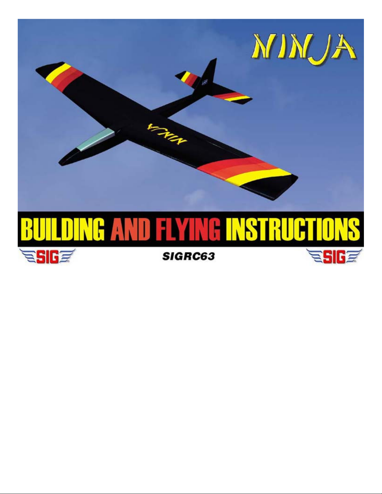
enough to please even the hottest flyers. Selecting the proper airfoil was without a doubt one of the most critical decisions
up wing. Low parts count and minimal sanding/shaping were also deemed necessary to reduce building
When designing the Ninja, our goal was to insure that it was one of the finest slope soaring kits available on the market (what
else would you expect from a Sig kit?). The design parameters we followed are listed below:
1. Outstanding Flight Performance
The model had to be very forgiving and easy to fly with no bad habits for low-time pilots. Also, it had to be aerobatic
in designing the Ninja. After trying a number of models with different airfoils, the Eppler 374 was chosen because of it's
superior inverted performance, high speed range, and it's excellent lift-to-drag ratio. Also, 1 degree of wingtip washout
has been incorporated into the foam wing cores to give the Ninja outstanding low speed stability.
2. Easy To Build
Modelers who value their leisure time want to spend less time in the work shop and more time flying. The rugged die-cut
Lite-Ply fuselage sides and formers that feature our popular Tee-Lock construction will greatly reduce the building time.
The precision-cut foam wing cores allow the modeler to build a wing in less than half the time it would take to build a
conventional builttime.
3. Appearance
We must have made a hundred different drawings before deciding on the final design of the Ninja (can't stand an ugly
model). Our goal was to maintain a low frontal area for the best possible performance while keeping the lines simple and
clean. The color scheme adds dramatically to the striking appearance of the Ninja, and it looks like it is going 100 miles
per hour when it's standing still.
Page 2
.
Radio Equipment Requirements
NOTE: If the optional rudder is to be used, a radio with at least 3 channels is required.
Notes Before Beginning Construction
Any references to left or right refer to your left and right as if you could be seated in the cockpit of the model. References to
inboard mean towards fuselage, while references to outboard means away from the fuselage.
the model's final finish. Use a pencil instead.
Identifying Kit Parts
5
The Ninja requires only elevator and aileron control, so any radio with 2 or more channels may be used as long as it is on an
aircraft approved frequency.
To build good flying models, you need a good straight building board. Crooked models don't fly well! The building board can be
a table, a workbench, a reject "door core" from the lumber yard, or whatever - as long as it is perfectly flat and untwisted. Cover
the top surface of the building board with a piece of celotex-type wall board or foam board, into which pins can be easily
pushed. Don't hesitate to use plenty of pins during assembly to hold the drying parts in the correct position.
Don't use ball point pens for making marks on the model during construction. If not sanded off, these marks will show through
Leave all die-cut parts in the sheets
until needed in construction. Then
remove the pieces from the sheets
carefully. If difficulty is encountered, do
not force the part from the sheet. Use a
modeling knife to cut it free.
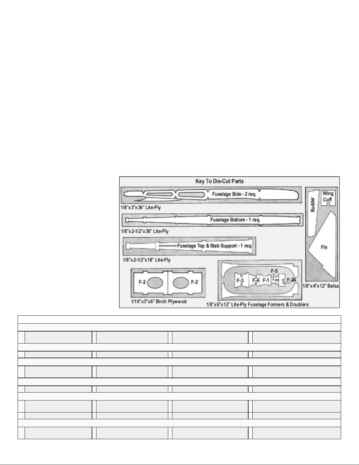
Die-cut plywood parts can be identified
by using "THE KEY TO DIE-CUT
PARTS". All of the other parts can be
identified by the "COMPLETE KIT
PARTS LIST" . Sort the different sizes
of sticks and sheets into individual piles
to avoid confusion during building. Cut
all long pieces of balsa first, followed
by medium length before cutting up any
full length strips into short pieces.
NOTE: Save any scrap balsa and
plywood for later use during the
construction of this model.
COMPLETE KIT PARTS LIST
Die-Cut Balsa Sheets
I 1/8"x4"x12" Fin, Rudder and
Wing Cuff
Sheet Balsa
10 1/16"x3"x30" Wing Sheeting 1 3/32"x3"x9" Canopy Sheeting
Stick Balsa
1 3/8"x3/4"x1-1/2" Nose Fill-In 4 1/4"x1/2"x30" Leading and
Trailing Edges
I 1/8" sq.x24" Canopy
Reinforcement
1 1/4"x12" Triangle Stock
Balsa Blocks
2 1"x1"x8" Wing Tips
Special Shaped Balsa
1 3/16"x4"x18" Pre-Cut
Stabilizer
1 1-3/8"x2-1/2"x3" Nose Block
2 5/16"x1-1/2"x24" Pre-Cut
Ailerons
1 3/16" x 1-1/2"x 18" Pre-Cut
Elevators
2 5/16" x 1-1/2"x 6" Pre-Cut Grooved
Torque Rod Blocks
Die-Cut Poplar Plywood (Lite-Ply)
2 1/8"x3"x36" Fuselage Side,
Canopy
I 1/8"x2-1/2"x36" Fuselage
Bottom
1 1/8"x2-1/2"x18" Fuselage Top,
Stab Support
1 1/8"x6"x12" Formers F-l, F-3, F-4, F-
Doublers
Page 3
.
I
I
3
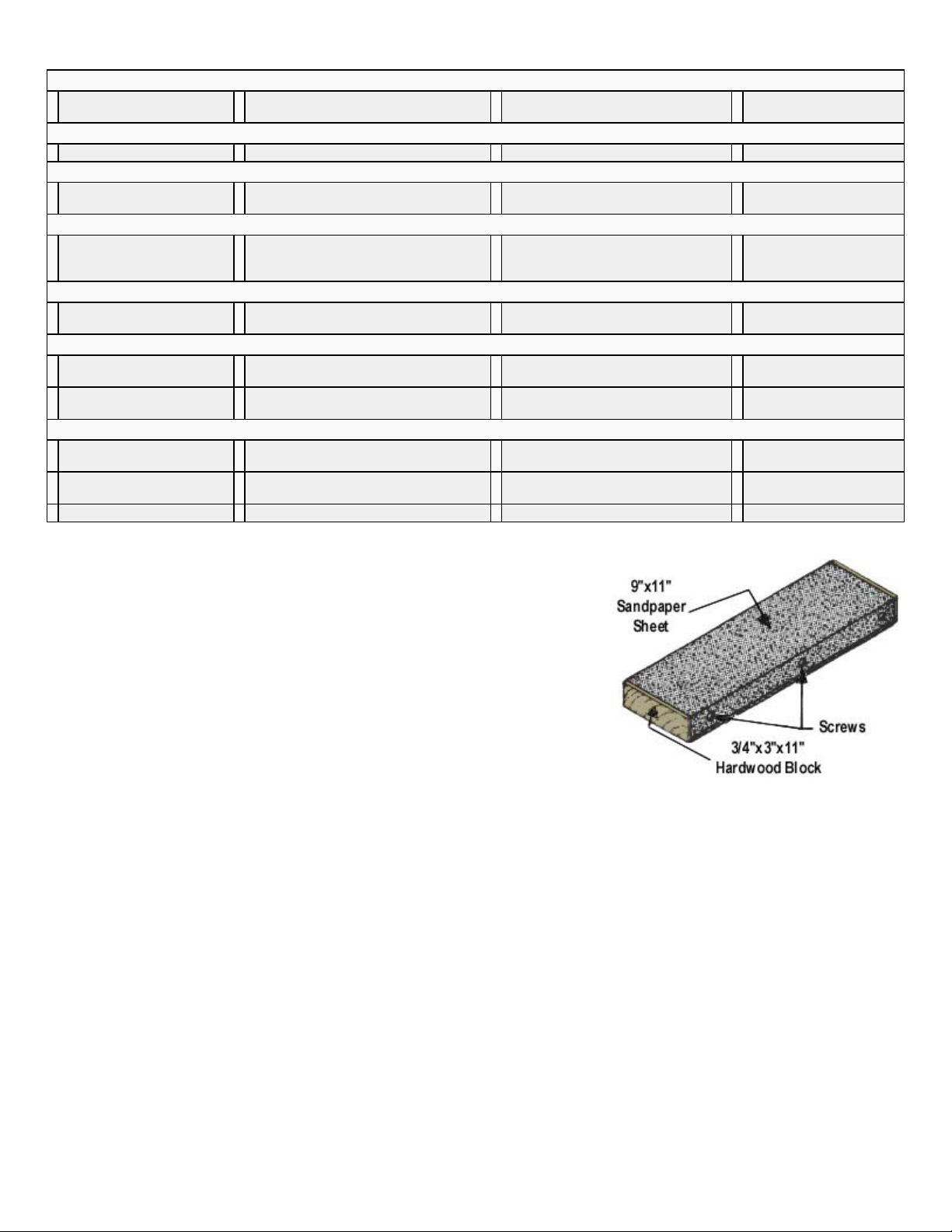
You can't get along without a good sanding block
Glues
Each of these types has different characteristics and advantages. Often times, the choice of which type to use is strictly a matter
several of the steps in these instructions.
Die-Cut Birch Plywood
1 1/16"x3"x6" F-2 Fuse
Former
Foam
I Foam Wing Core
Hardwood
I 3/8"x5/8"x I-5/8" Basswood
Wing Hold Down Block
2 1/4"x3/8"x I" Basswood Servo Mounts I 1/4" dia.x1-1/12" Birch Wing Hold-
Down Dowel
Formed Wire Parts
1/32"dia. Canopy Latch 1 4-40x8" threaded rod L.H. Aileron
Torque Rod (with 1/8" o.d.x4" brass
bearing)
I 4-40x8" threaded rod R.H. Aileron
Torque Rod (with 1/8" o.d.x4" brass
bearing)
Plastic
I .030x1/2"x12" ABS Plastic
Skid
Miscellaneous Parts
I 2"x24" Fiberglass Tape (for
wing center joint)
1 Photo lllustrated Instruction
Book
I 1/16"x1/2"x18" Servo Tape (for
mounting skid and servo)
I 4"x8" Decal
Hardware
2 #2x1/2"; Sheet Metal
Screws (for control horn)
I Small R.H. Nylon Control
Horn
I Pkg. of 10 Easy Hinges
I 10-32 x I" Nylon Wing Bolt 2 4-40 Nylon Aileron Connectors
I .190"o.d.x24"; Outer Nylon Pushrod
Tubing (for elevator)
I .130"o.d.x 28"; Inner Nylon Pushrod
Tubing (for elevator)
An assortment of different size sanding blocks are indispensable tools for model
construction. A good general purpose block can be made by wrapping a 9"x11"
sheet of sandpaper around a piece of hardwood or plywood. Use three screws
along one edge to hold the overlapped ends of the sandpaper. Put 80-grit paper
on the block during general construction. Switch to 220-grit paper for final finish
sanding just before covering.
Another handy block can be made by gluing sandpaper onto a 24" or 36" long
piece of aluminum channel stock. Most hardware stores carry a rack of aluminum
in various sizes and shapes. This long block is very useful for sanding leading
and trailing edges accurately.
18"x24" Plan
2-56 R/C Links
(2/ailerons, 1/elevator)
4 2-56x10"; Threaded Rods
(2/ailerons, 2/elevator)
There are so many different glues available today for model construction that it can be confusing even for the experienced
modeler. To simplify matters, most glues can be classified as one of four basic types:
1. Fast cyanoacrylate adhesives (abbreviated in these instructions as "C/A") such as SIG CA, Hot Stuff, Jet, etc ...
2. Easy-to-use water-based glues such as SIG-BOND (yellow) and SIG SUPER-WELD (white).
3. Super strong (but heavier) two-part epoxy glues such as SIG KWIK-SET (5-minute cure) and SIG EPOXY (3-hour cure).
4. Traditional solvent-based model cements such as SIG-MENT.
of personal preference based on your experience with a previous model. However, because of the vast use of Lite-Ply and
hardwoods in the NINJA, we have found that the C/A glues seem to work the best for general construction. In fact, the
construction sequence of the fuselage is designed with the use of C/A glue in mind. Other glues could be used, but C/A is
recommended as our first choice because of its ability to penetrate an already assembled joint. In other words, the fuse parts
can first be assembled dry (without glue), the alignment checked and adjusted, and then the glue can be applied to the joints.
You should also have on hand some epoxy (both 5-minute and slow dry) and SIG-BOND because these glues are called out in
Page 4
.
can be used to tack assemblies together, but these joints should be glued again later with medium or thick C/A. Thin C/A is also
plywood fuselage parts. The extra thickness allows the glue to fill small gaps, but it dries a little slower than thin C/A. If you want
only one type of C/A, use medium thickness.
This thickest formula is good for filling large gaps and building up strong fillets at joints requiring extra strength. It also dries slow
like a fuselage side and a fuselage doubler.
even more.
This can be used to separate parts, but you'll probably use it for unsticking your fingers more than anything else!
About The Building Sequence
study the plan before beginning construction.
WING CONSTRUCTION
sanding block.
sanding block for final touch
-
up if necessary.
SIG CA, like most brands of cyanoacrylates, comes in three viscosities thin, medium, and thick. An accelerator spray and
debonder are also available and are described below.
SIG CA THIN
Watery in consistency, thin C/A should only be used when the two parts to be joined are in perfect contact with zero gap.
Capillary action pulls this glue deep into the wood resulting in a very strong bond and it dries in just a few seconds. Thin C/A
necessary for installing EASY HINGES.
SIG CA MEDIUM
Our medium thickness C/A is excellent for almost any step during construction, and is particularly recommended for gluing the
SIG CA SLOW
enough to allow you to apply it to one part and position it on another before it dries. (With the thin and medium C/A's, the parts
must be in contact and positioned correctly before glue application.) This feature is useful when laminating large sheeted areas
SIG KWIK-SHOT ACCELERATOR
Spraying accelerator on C/A (any thickness) will cure it almost instantly. Although C/A is fast, it's sometimes nice to speed it up
DEBONDER
CAUTION:
Some people have experienced allergic reactions when exposed to epoxy or cyanoacrylate
glues. This is very rare. However, it is always important that such glues, and also paints, thinners
and solvents, be used with adequate ventilation to carry fumes away.
The quickest and most efficient way to complete a model is to work on several pieces at the same time. While the glue is drying
on one section, you can start on or proceed with another part. Keep in mind that the number sequence used in these
instructions book was chosen as the best way to explain the building of each major component and is not intended to be
followed in exact one-two-three fashion. Start on the wing at NO.1 and after doing as many steps as is convenient, flip over to
"FUSELAGE CONSTRUCTION" and do a step or two there, then back to "WING CONSTRUCTION" and so forth. You will
arrive at points where you can go no farther until another component is available. Plan ahead! Read the book completely and
1.
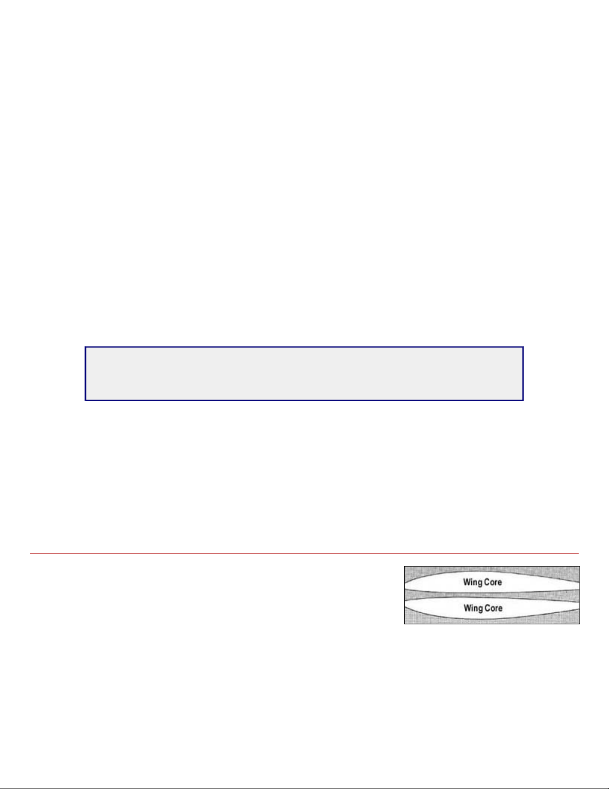
The foam wing cores are shipped in the block from which they were cut. Untape
the foam block and remove the wing cores.
NOTE: Save the foam shipping cradles as they will be needed later in construction.
2.
Lightly sand any irregularities or cutting wire marks from the foam wing cores with 220 grit sandpaper used on a long
3.
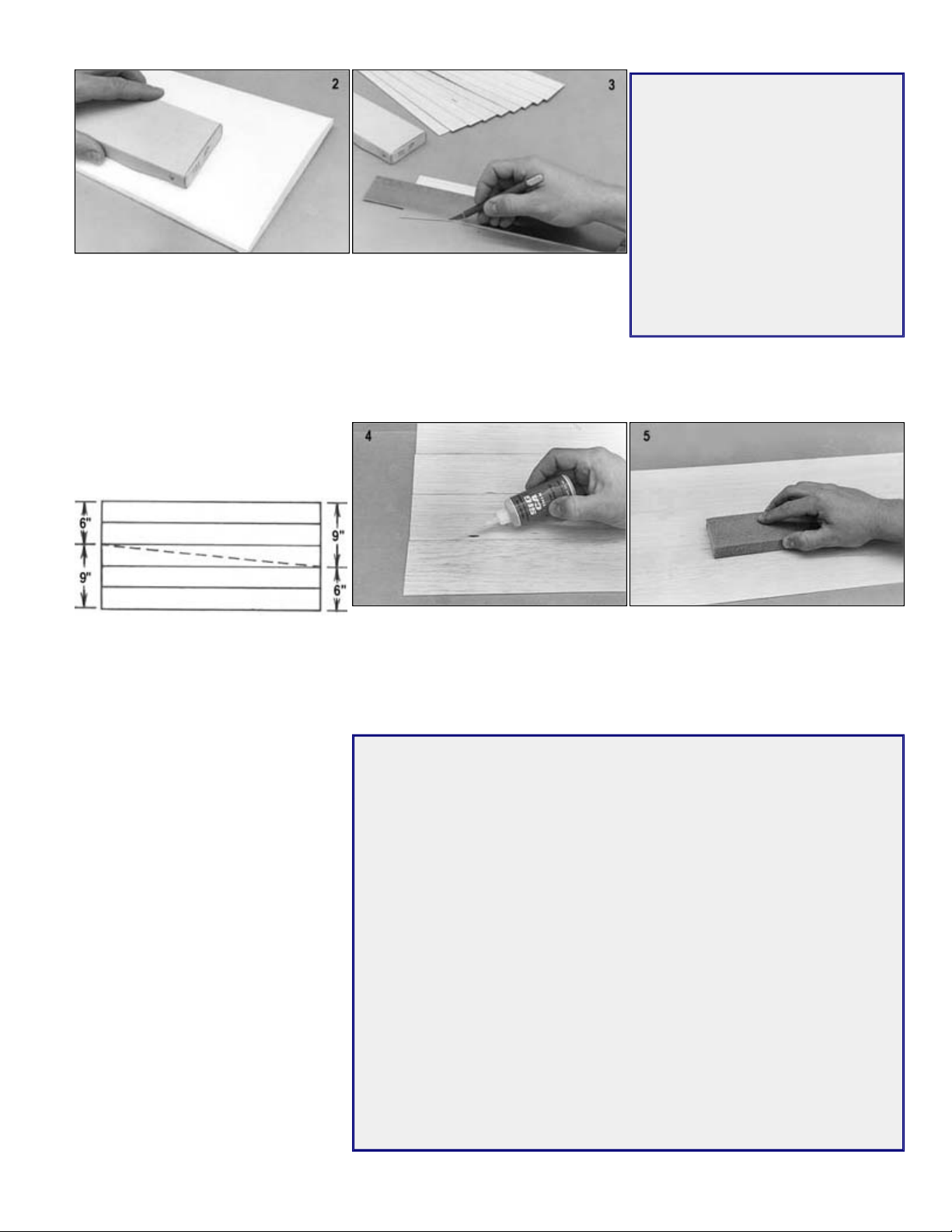
Using a metal straight edge, true up the edges of the ten 1/16"x3"x30" balsa sheets provided for covering the wing. Use a
Page 5
.
Place a sheet of wax paper onto your building board. Glue five of the 1/16"x3"x30"
five balsa sheets together in the same manner.
wing skins, ready to be glued onto the
NOTE: The wing skins will be glued onto the foam cores with the grain running parallel to the trailing edge. Mark each of the
The following instructions refer to the use of Sig Core
-
Bond
Apply a thin, even coat of Sig Core
Bond
to both sides of the foam wing cores and
back of the Core
-
Bond can carefully.
repositioned once contact is made. Then
carefully lower the trailing edge ONLY of
the next step.
THE SECRET OF A PERFECT FOAM
WING
It's a simple matter of a FLAT table.
Most tables are not flat, as can be
seen by checking them with a good
straightedge. If a foam core is covered
on a bowed or twisted surface, then
the wing will be bowed or twisted. And
a table that checks out true but is
4.
balsa sheets together with Sig thin C/A glue. To prevent a hard-to-sand seam,
apply the C/A glue sparingly. Repeat the above procedure to glue the remaining
5.
Using a large sanding block with 150-grit sandpaper, carefully sand the glue seams smooth on both sides of the 5-sheet
layouts. Be careful not to sand too much, just enough to remove any edges that might be sticking up.
6.
Cut both 5-sheet layouts diagonally in
two, as shown by the dotted line in the
diagram to the right. This will yield four
flexible and will yield as you press on
it will also spoil a wing. The ideal
working surface is a sheet of plate
glass. Or, it is possible to find a thick
piece of plywood that is perfectly true.
foam cores.
four wing skins as to whether they go on top or bottom, right or left of the foam core, and also mark which side of the skin
the glue should be applied.
7.
to the four wing skins. Since they are
coated on both sides, stand the foam
cores on end to dry. Allow the cores and
the wing skins to dry completely - at
least one hour. Core-Bond must be
completely dry for good adhesion. Read
and follow the full instructions on the
8.
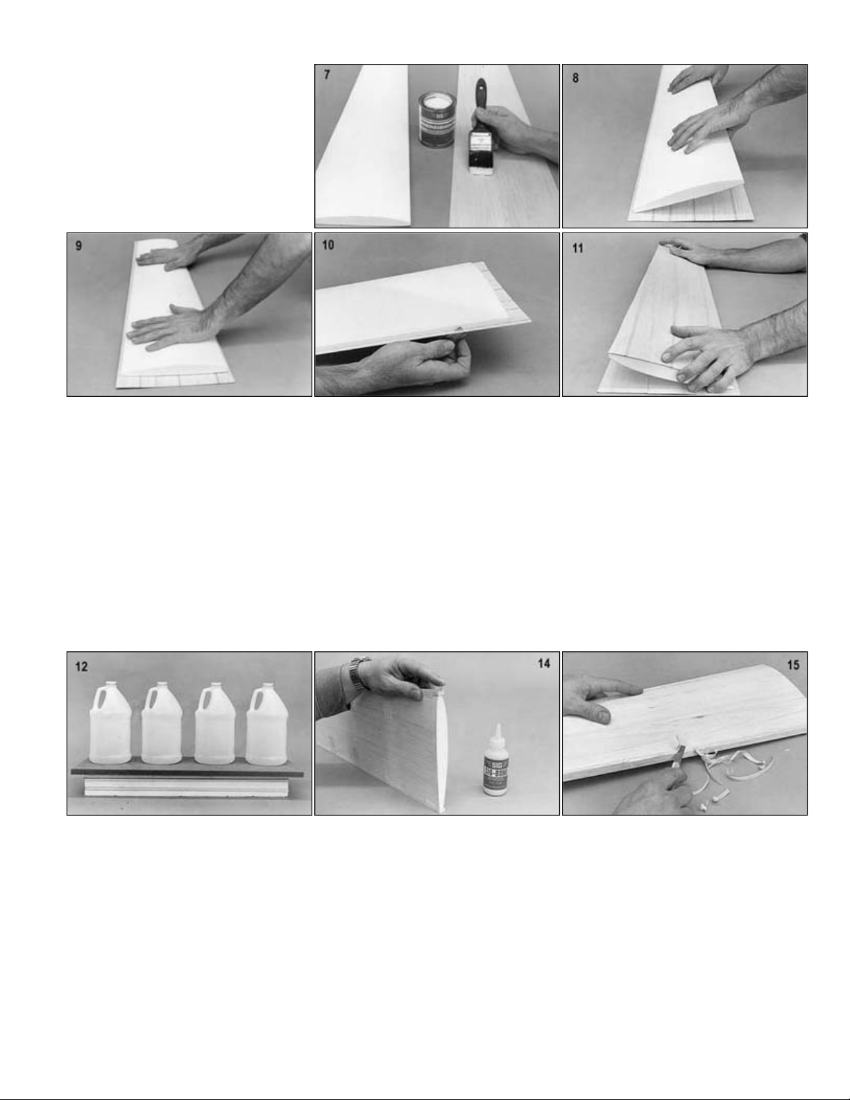
Place one of the balsa wing skins, glue
side up, on a perfectly flat building
board. Remember that the wing skins
are to be attached to the cores with the
grain of the balsa running parallel to the
trailing edge. Hold the trailing edge of
the foam core just above the wing skin.
Make sure it is properly aligned before
you let it come in contact with the wing
skin, because it cannot be removed and
the foam wing core into contact with the
balsa wing skin. Proceed immediately to
-
CHOOSE THE RIGHT GLUE
FOR APPLYING YOUR WINGSKINS
Sig Core-Bond is recommended for applying the wing skins to the foam wing
cores.
This is a special adhesive, designed exclusively for skinning foam wings. it is
light and strong, and most important easy to use, even for modelers who have
never covered a foam wing before. As many modelers have found out the hard
way, some so-called "foam wing" glues contain very volatile solvents that make
them touchy to use. If the wing skin is put on the foam core while the glue is still
even slightly wet, the volatile solvents will be trapped under the wing skin and
will attack and dissolve part of the foam wing core, ruining the wing. Because it
is waterbased, and doesn't contain harmful solvents, Sig Core-Bond won't
cause this type of damage.
Our second choice recommendation, for those looking for a faster method, is to
use 3M Spray Adhesive #77 for gluing the skins to the foam wing cores. Work
with only one foam wing panel and one balsa wing skin at a time. Spray the
glue onto one side of the foam core and onto one wing skin. Allow the glue to
dry for several minutes, until it becomes aggressively tacky but not visibly wet,
before putting the skin in place. Use caution, because if the glue is too wet
when you apply the skin, the foam core could be damaged by trapped glue
solvents.
Page 6
.
Roll the foam core forward onto the wing
skin with a rocking motion until the entire
skin is attached.
time.
11. Repeat steps 1 through 10 to skin the other three sides of the foam cores.
After sheeting all four sides of the wing panels, stack the panels back in the foam shipping cradles. Place on a flat surface
piece of plywood larger than the foam.) Allow to dry overnight before proceeding.
foam, not into it.
and straight pins to hold the pieces in place until dry.
BUILDER'S TIP: Wrap the tip of the blade with masking tape to prevent gouging of the wing skins.
(NOTE: A pencil line down the center of the leading edge from root to tip will help keep the shape true all along the way.)
place until dry.
9.
10. Trim off most of the excess balsa wing
skin, to within about 1/16" of the foam
core, with a sharp single-edge razor
blade or a modeling knife. It is not
necessary to trim the balsa completely
flush with the foam wing core at this
12.
or building board and weight down. (Notice in this picture that four one gallon jugs filled with water have been placed on a
13. Sand the edges of the balsa wing skins flush with the foam core with a long sanding block. Take care to sand just up to the
14. Glue the 1/4"x1/2"x30" balsa leading and trailing edges in place with Kwik-Set epoxy or Sig-Bond glue. Use masking tape
15. Carve the leading and trailing edges to their approximate shape with a #26 X-Acto blade.
16. Finish shaping the leading and trailing edges to shape. Finish shaping the leading and trailing edges with a long sanding
block.
17. Glue in place the 1"x1"x8" balsa wing tip blocks with epoxy or SigBond glue. Use masking tape or a straight pin to hold in
18. Roughly carve the wing tip block to profile shape with a #26 X-Acto blade, as shown in the photo. For now, just rough out
the block. Leave plenty of extra wood at the trailing edge, for final carving later on after the aileron is attached (NOTE: This
final shaping will be done in step 27).
Page 7
.
the wing halves as shown. If necessary, sand the root ends of the wing panels to make the center joint fit correctly together.
wing panels together with Sig Epoxy Glue or Kwik
between the two halves is completely filled.
1/2"x6"
the grooved aileron stock.
of the wing. Use a ruler to line them up with the bottom surface of the wing. Again,
down) in the ailerons, which makes for smoother turn and roll characteristics.
thin coat of epoxy glue on the wing. Next
out and remove all excess glue.
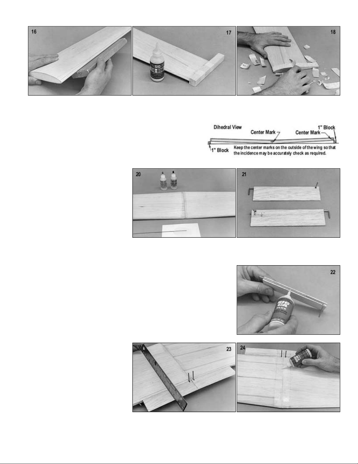
19. The angle already cut into the ends of the foam wing halves sets an approximate correct dihedral angle. To check it, set up
20. Using a soft lead pencil, mark center lines on the leading and trailing
edges of each wing panel. When joining the two wing panels together,
line up these marks to properly align the two wing panels. Glue the
-Set Glue. Use
plenty of glue where the balsa sheeting meets so that the joint
21. Locate the two pieces of 5/16"x1-
aileron stock that have been grooved to
accept the aileron torque rods. Cut a
1/8" notch in each of them, 1/4" from the
end as shown in the photo. Be certain
you make a left and a right, and keep in
mind that the aileron torque rods must
exit the bottom of the grooved aileron
stock.
22. Glue the torque rods in place in the grooved aileron stock. Glue the brass bearings only! Be very careful not to get any glue
inside the brass bearings or on the wire. Notice that the outer end of the brass bearing should be even with the outer end of
23. Glue the torque rod/grooved aileron stock assemblies in place on the trailing edge
be very careful not to get any glue in the bearings or on the wires. Notch out the
back side of the wing trailing edge slightly to allow forward movement of the
aileron torque rods.
NOTE: The aileron torque rods have been pre-bent so that the threaded portions
leans rearward slightly inside the fuselage (see the wing crosssection on the
plans). That small angle will provide a bit of differential movement (more up than
24. Reinforce the wing center joint, top and
bottom, with 2" glass cloth tape and
epoxy glue. DO NOT OMIT THIS STEP!
We have found it easiest to first smear a
lay the tape over the glue. Then holding
one end of the tape so it won't slip,
squeegee the glue through the tape with
a small paddle of scrap balsa. Scrape
over the tape several times to smooth it
Page 8
.
ASSEMBLY section.
with Kwik
An alternate method of attaching the glass tape is to lightly spray one side of the tape with a
spray adhesive (such as 3M "77"). Place the tape on the wing joint (sticky side down) and
smooth out any wrinkles. Soak the glass tape with thin C/A.
The spray adhesive simply holds the tape in place - it won't affect the strength of the C/A. A
second coat of C/A will help fill in the weave of the fiberglass, resulting in a smoother surface.
Rub the second coat with your finger (protected with a plastic wrap - keep it moving) to smooth
out the glue. Use a small fan to keep the fumes away from your face. When dry, sand lightly to
remove any rough spots while avoiding sanding into the fiberglass tape.
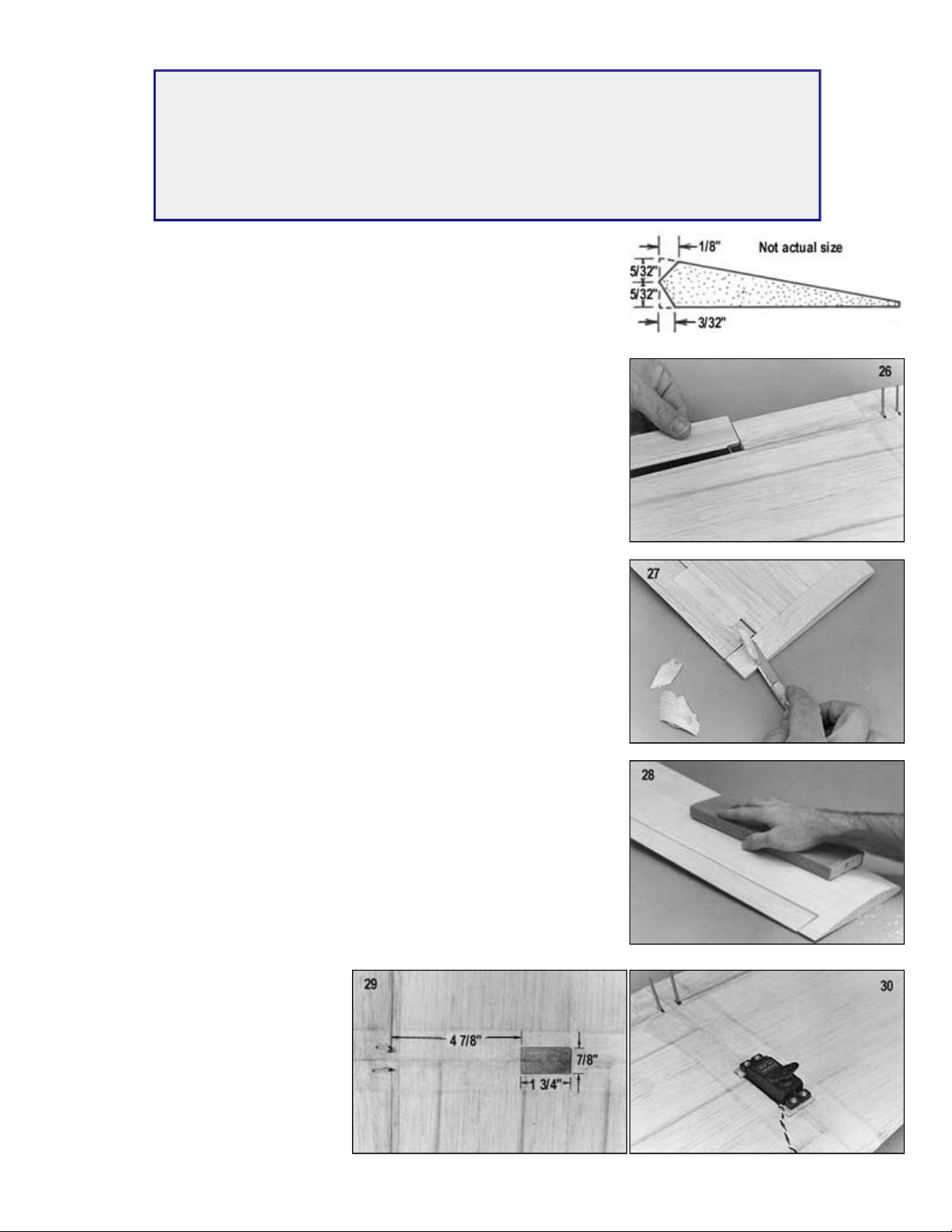
25. Draw shaping and center lines on the leading edge of the 5/16"x1-1/2" shaped
aileron stock as shown. Roughly carve to shape with a razor blade and finish
shaping with a sanding block.
26. Position the aileron on the back of the wing and mark the location of the aileron
torque rod.
Carefully drill into the aileron leading edge with a 3/32" dia. drill to receive the
torque rod wire.
Next cut a slot in the front of the aileron allowing the torque rod wire to fit flush.
NOTE:
Do not glue ailerons in place at this time. They will be installed during the FINAL
27. Temporarily install the ailerons with masking tape.
Then finish carving and sanding the wing tip blocks to their final shape with a long
sanding block.
NOTE:
The aileron end of the wing tips should be the same thickness as the aileron
trailing edge.
28. Carefully block sand the entire wing for the final time with 150-220 grit sandpaper.
29. Using the dimensions shown in the photo, draw the exact location of the aileron
servo cutout on the bottom wing sheeting.
Using a modeling knife, carefully cut out the outlined area of sheeting.
Next, excavate the foam down out of the cavity, all the way down to the balsa top
sheeting on the opposite side. When finished, coat the entire inside of the cutout
-Set epoxy glue.
30. Two 1/4"x3/8"x1" basswood servo rails
have been provided for mounting the
aileron servo. Cut away the balsa wing
sheeting and epoxy glue the rails in
place.
NOTE: The dimensions of your particular
servo will determine the exact location of
the servo rails.
Page 9
.
FUSELAGE CONSTRUCTION
will not be necessary to change the pushrod hole location, simply mount the servo a little bit higher.
rough edges on these parts with a small sanding block with 220 grit sandpaper.
dry.
steps 102
-
107 at this time, before going any further.
rubber band.
push rod tubing. Be sure to position the push rod notches in F
-
4 towards the bottom, as shown in the drawing.
NOTE BEFORE BEGINNING:
The Ninja was designed around standard servos (such as the Futaba 848 and Airtronics 94102) that are about 1.5" tall. If
you are planning to use older standard servos that are slightly taller than this, it may be necessary to move up the location
of the outer pushrod hole in former F-2 to fit your particular servo (see step 33). If smaller than standard servos are used, it
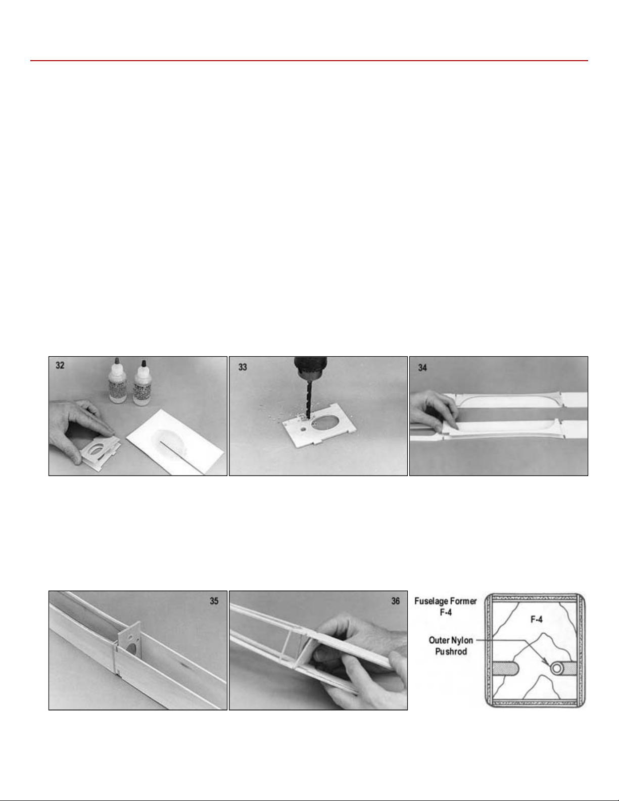
31. Carefully remove the die-cut Lite-Ply fuselage sides, top, bottom, formers, and doublers from their sheets. Remove any
32. Glue together the two die-cut plywood F-2 pieces using Kwik-Set epoxy or slow C/A. Clamp together or weight down until
33. There are two small dimples in the F-2 former. The top center dimple is for the wing hold down dowel; drill this one out with
a 1/4" drill bit. The second dimple that is located near the side of the former, is for the elevator outer nylon pushrod tubing;
drill it out with a 3/16" drill bit.
NOTE:
Even though the NINJA is designed for 2 channels (aileron/elevator), and it flies beautifully that way, some people will
undoubtedly wish to add a third channel for rudder control. If you want to consider this option, refer to "Optional Rudder"
34. Glue the die-cut plywood fuselage doublers to the die-cut fuselage sides using slow C/A or Kwik-Set epoxy, and allow to
dry. Be sure to make one left side and one right side!
35. Install former F-2 in it's proper location between both fuselage sides and hold it in place with either masking tape or a
36. Working from F-2 rearward, slip fuselage formers F-3, F-4, and F-5 into place. Put a rubber band around the fuselage at
each former location to hold it tightly together.
NOTE:
The die-cut notches in the fuselage formers F-3, F-4, and F-5 are for properly locating and gluing in place the outer nylon
Page 10
.
it snaps into it's proper location between
1 and secure it
proceeding.
Again, using medium viscosity C/A glue,
NOTE: When gluing the bottom sheet in
2, you
will have to gently bow the bottom so
NOTE: The top of the nose block has more curvature than the bottom of the block.
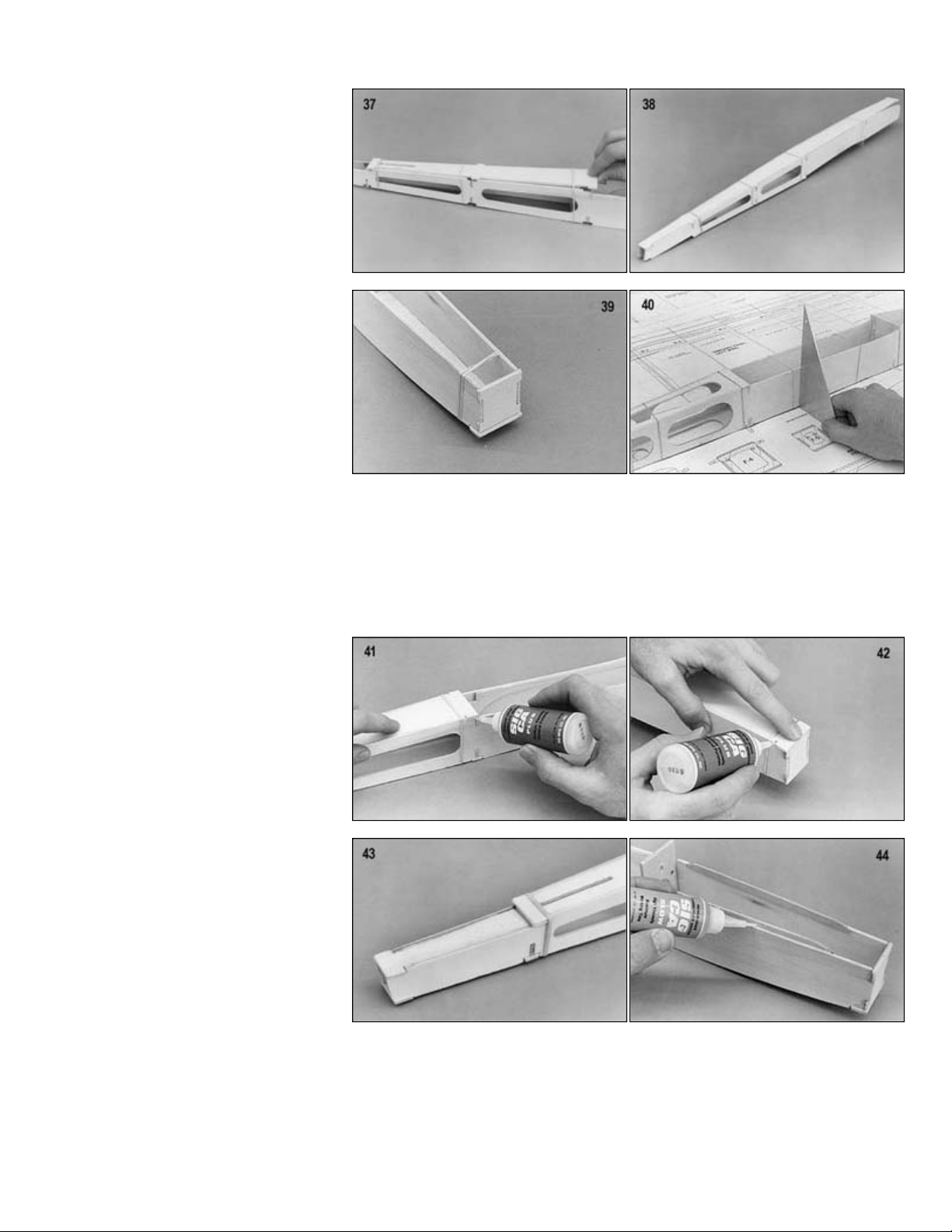
37. Slide the die-cut Lite-Ply fuselage top
rearward, under the rubber bands, until
the fuse sides.
NOTE: The Tee-Lock tabs on the
fuselage top, bottom, and formers are
made slightly oversize and will protrude
past the fuselage sides at this time.
These will be sanded off later after the
fuselage has been completely
assembled .
38. Slide the die-cut Lite-Ply fuselage
bottom rearward, under the rubber
bands, until it snaps into it's proper
location between the fuse sides.
39. Install fuselage former F-
in place with a rubber band.
40. Place the fuselage over the top view to check the overall alignment of the fuselage to make sure it is straight and square.
Use a 90 deg. triangle to verify that the sides are perpendicular. Correct if necessary by gently twisting the fuselage before
41. When satisfied with the fuselage alignment, tack glue all of the TeeLock tabs (except the very last one on the bottom at
former F-1) from the outside using medium viscosity C/A glue. This will keep the fuselage square as you proceed with the
final gluing.
42.
carefully glue all the parts permanently
to each other from the inside of the
fuselage. Be sure to glue both sides of
each former to the top, bottom, and
sides of the fuselage. Do not remove
the rubber bands until all the glue joints
have completely dried.
place between formers F-1 and F-
that it follows the curve of the fuse
sides. Bow it into position so that it fits
perfectly flush with the fuselage sides
and hold securely while gluing with C/A.
43. Install the die-cut Lite-Ply stab support
so that it is flush with the top of the
fuselage sides. Glue securely.
44. Make two canopy side rails from scrap 1/16" birch plywood. Use the pattern that is provided on the plan and glue them in
place as shown.
45. Glue in place the preshaped balsa nose block and the 3/8"x3/4"x1-1/2" balsa fill-in.
Page 11
.
with the top of F
Lock stubs and round the edges of the fuselage with a sanding
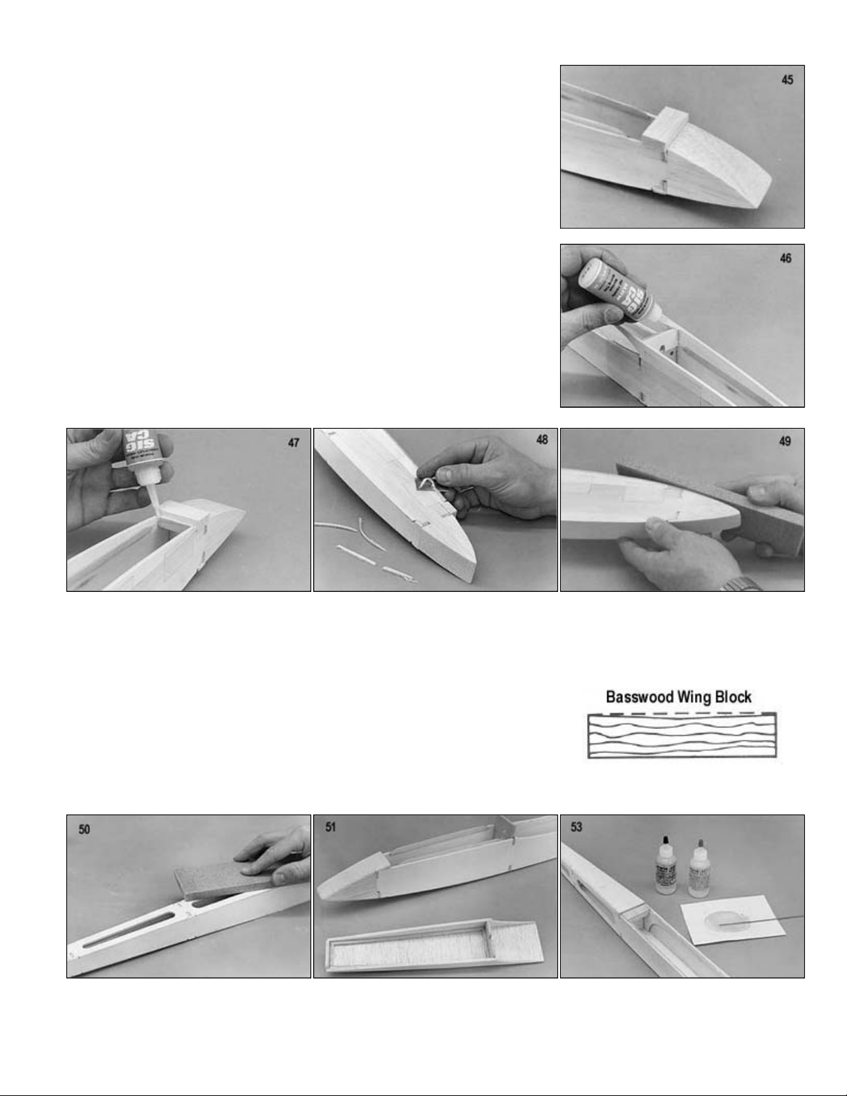
53. Epoxy glue the 3/8"x5/8"x1
-
5/8" basswood wing hold down block into notches in the fuselage doublers.
46. Tape the die-cut Lite-Ply canopy sides in their proper locations along the top of
the fuselage sides. Slide former F-2A down between the canopy sides until flush
-2 and glue it to the canopy sides. Extreme care must be taken to
insure that no glue seeps down onto former F-2 or the fuse sides.
47. Using the pattern on the plan, make the front former for the canopy from scrap
Lite-Ply and glue in place. Again, extreme care must be taken to insure that no
glue is allowed between the former and the fuse sides.
48. Cut and glue in place cross-grain pieces of 3/32" balsa sheeting on top of the
canopy sides. Trim off the excess balsa.with a single-edge razor blade
49. Retape the canopy in place on the fuselage and sand the nose block to exact
shape with a sanding block.
50. The fuselage is now ready for final sanding. Sand off all Tee-
block. Start out with 150 grit sandpaper and switch to 220 grit sandpaper for the final sanding.
51. Remove the canopy from the fuselage and add 1/8" sq. balsa reinforcement to the inside corners of the canopy.
52.
Following this pattern, sand a slight bevel in the top of the wing hold down block.
This bevel allows the wing to properly seat itself in the wing saddle.
Page 12
.
Mounting The Wing To The Fuselage
there should be a small indentation in the leading edge.
hole 1 inch deep.
edge of the wing.
Trial fit the wing onto the fuselage wing saddle making sure it is properly seated. If not, slightly enlarge the dowel hole in the
wing leading edge until it does seat properly.
can't move. Next, carefully measure 1/4"
location for the wing hold down bolt. Drill
nylon bolt to pass though.
cut 1/8" balsa wing cuff with a sanding block. Carefully glue the cuff in place onto the wing
over center of the wing dowel slot in the former and glue the wire latch in place. Glue only the bottom leg of the wire latch to
the fuse former.
54. Locate the 1/4" dia. x1-1/2" wing hold down dowel and sharpen one end to a point
- keep the point symmetrical and centered. Push the dowel into the hole in F-2 so
that only the point remains sticking out into the wing opening. Slide the wing into
position, making sure it is centered on the fuselage. When you remove the wing,
55. Drill a 1/4" diameter hole through the leading edge at the indentation. Make the
56. Remove the dowel from F-2 and slide it into the hole in the wing leading edge,
pointed side first, leaving about 1/2" of the dowel protruding out from the leading
57.
58. Remove the wing from the fuse and glue the wing dowel permanently in place in the wing with Kwik-Set epoxy glue and let
dry.
NOTE: Do not use C/A glues for this step, as it will melt the foam wing core!
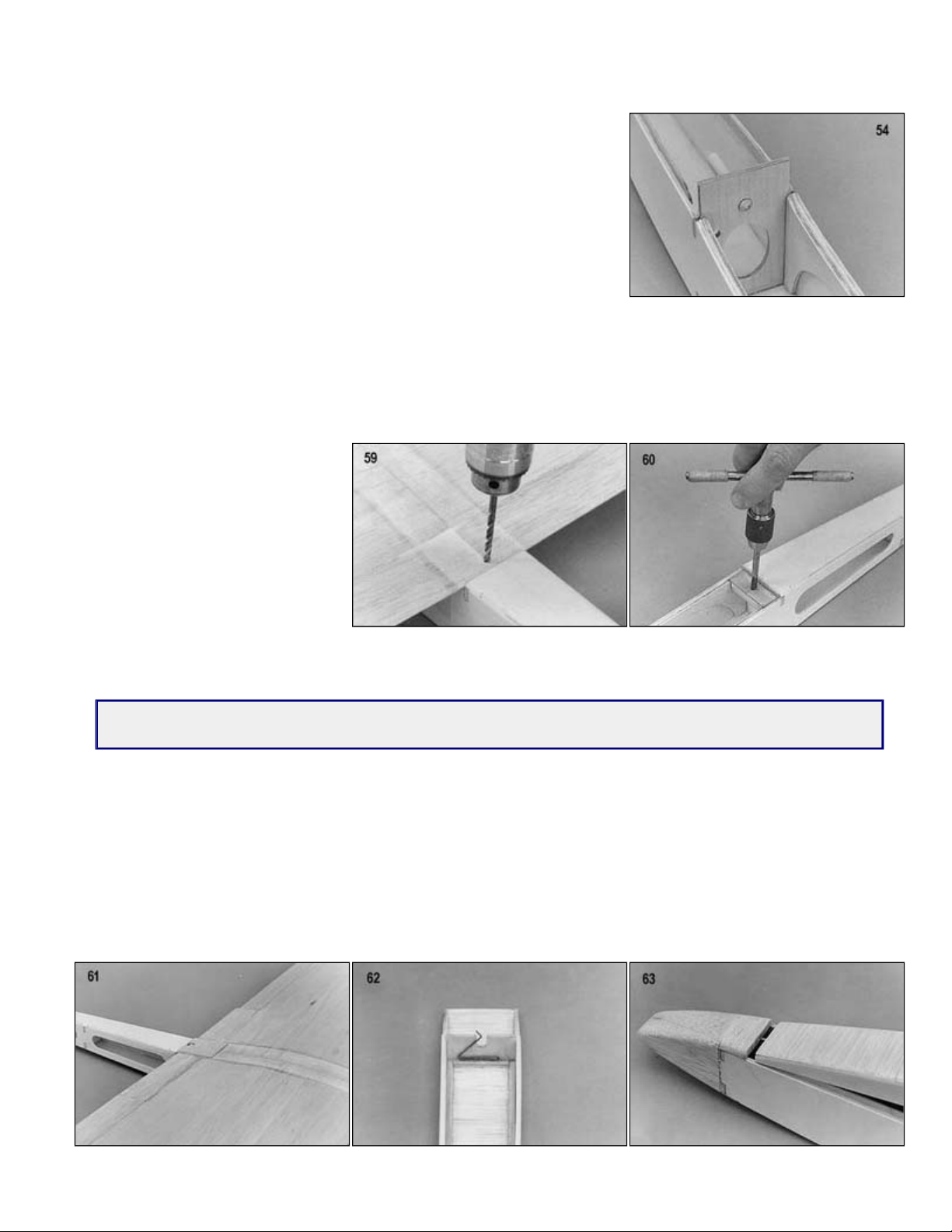
59. Install the wing on the fuselage and
properly align it. Measure to make sure
both wing tips are the exactly same
distance from the rear end of the
fuselage. Tape the wing to the fuse so it
in front of fuse former F-3, and mark the
through the wing and the basswood
block at the same time with a 5/32" drill.
60. Tap the basswood block with a 10-32 tap. Take the wing off and redrill the hole in the wing with a 3/16" drill to allow the
BUILDER` TIP: Stengthen the threads and the wing bolt holes with a few drops of thin C/A glue. When dry, clean
the excess glue from the threads with a 10-32 tap.
61. Sand a bevel in the top of the die-
making sure that no glue is allowed onto the nylon wing bolt.
62. Position the pre-bent 1/32" music wire canopy latch onto the front of fuselage former F-2A. Make sure the latch is slightly
63. Make a front hold down pin for the canopy out of a scrap piece of wire or a round tooth pick. Drill a hole in the front former
of the canopy and glue in place. Also drill a hole in the balsa fill-in to accept the pin.
Page 13
.
Elevator Servo And Pushrod Installation
glue the tubing permanently to each of the fuse formers and to the fuselage side between formers F
-
2 and F
-
3.
where the servo will be mounted.
Apply the servo tape to the back of the
spacer.
64.
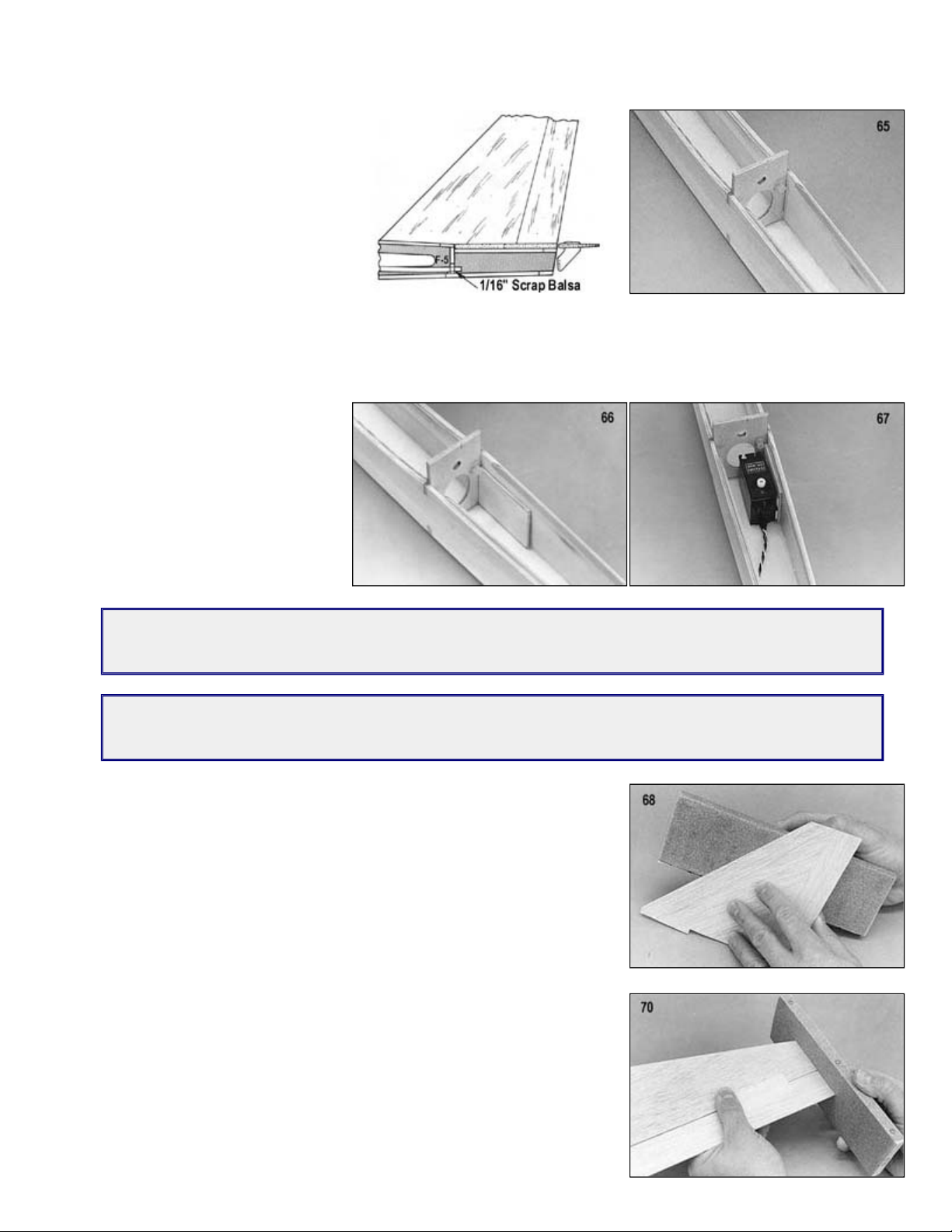
Cut a small piece of 1/16" scrap balsa,
3/16" wide x1/2" long. Glue it onto the
fuselage bottom sheeting, in the push
rod slot at the bottom of former F-5.
(See drawing.) This shim is to elevate
the entire pushrod slightly to keep the
R/C link from rubbing on the bottom
sheeting.
65. Install the 3/16" o.d. nylon outer pushrod tubing by passing it through the pre-drilled hole in former F-2 and through the die-
cut notches in F-3, F-4, and F-5. Make sure the tube extends past former F-5 for 1/4". Also, make sure that the other end
extends forward of former F-2 for 3/16". When you have the length properly determined, cut off the excess. Then epoxy
66. For adequate servo arm clearance, the
servo must be moved slightly inboard.
Using the pattern on the plan, make a
spacer for the servo from 3/32" balsa,
and glue it to the inside of the fuselage
67.
servo and remove the paper backing.
Press the servo onto the 3/32" balsa
BUILDER'S TIP: Apply a thin coat of slow C/A to the balsa spacer and allow the glue to dry before taping the
servo in place. This will greatly increase the bond of the servo tape. The remainder of the elevator pushrod
installation details will be done later during "Final Assembly", after the tail surfaces are mounted to the fuselage.
FLYER'S TIP: If you are new to the sport of slope soaring or your favorite site has a rough landing area, we
recommend reinforcing the fuselage with 3/4 oz. glass cloth and epoxy. Apply the glass cloth and epoxy to the
outside of the fuselage from former F-4 forward to the nose.
Fin And Rudder
68. Glue the die-cut balsa fin and rudder together using medium viscosity C/A glue.
When dry, sand the seam smooth.
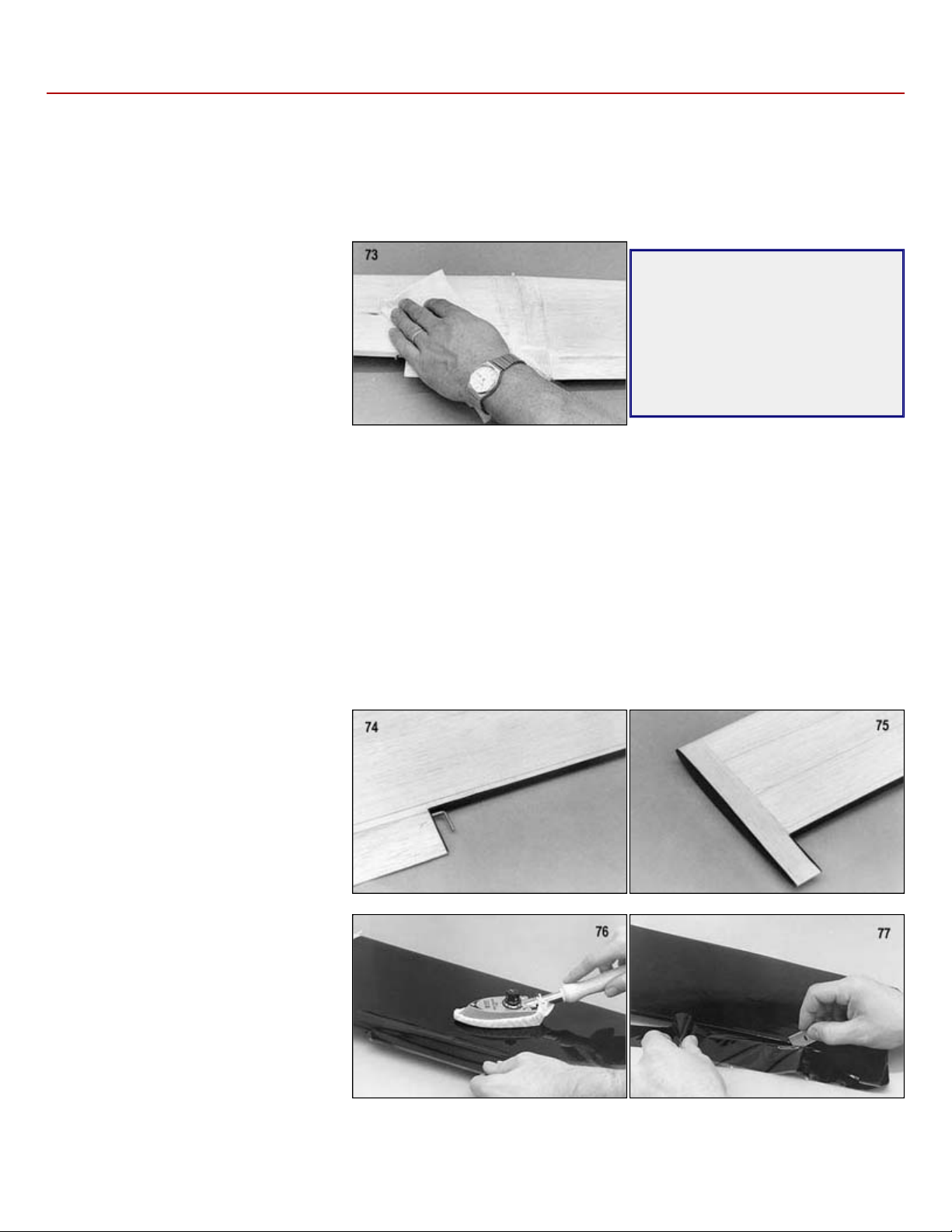
69. Round the leading edge, trailing edge, and the tip with a sanding block and 150
grit sandpaper. Do not sand the alignment tab on the bottom of the fin.
Stabilizer And Elevator
70. Sand the pre-cut 3/16" balsa stabilizer leading edges round except for the short
length in the center, which should be left flat to fit against the back of F-5.
71. Locate the pre-cut 3/16" balsa elevator and sand the leading edge round with a
sanding block.
72. Temporarily tape the elevator to the back of the stabilizer, then use a sanding
block to sand both of them at the tips until they match perfectly. The tips can be
left square or sanded round if you prefer.
Page 14
.
COVERING AND FINISHING
grit sandpaper.
The structure that is to be covered must
All of the Ninja prototypes were covered with Sig Supercoat Iron
You will notice in the following photos of the covering process, that we prefer to use a "sock" on our sealing iron. This is not
gauge to set the temperature of your iron to the exact setting the covering manufacturer recommends.
Covering The Wing
Start by covering the back of the trailing
then the top of the wing. This leaves the
where it is less visible. Cut the covering
the iron to shrink the covering as you go along. Trim the covering off flush with leading edge and reseal it with the iron.
Preparing For Covering
Regardless of what type of covering material you elect to use, a good covering job starts with good surface preparation.
You can't hide poor workmanship with covering material! Fill any small surface gaps with a light-weight filler or spackling
paste. Sand the entire model including the ailerons and tail surfaces, with 220 grit sandpaper, then again with 360 or 400
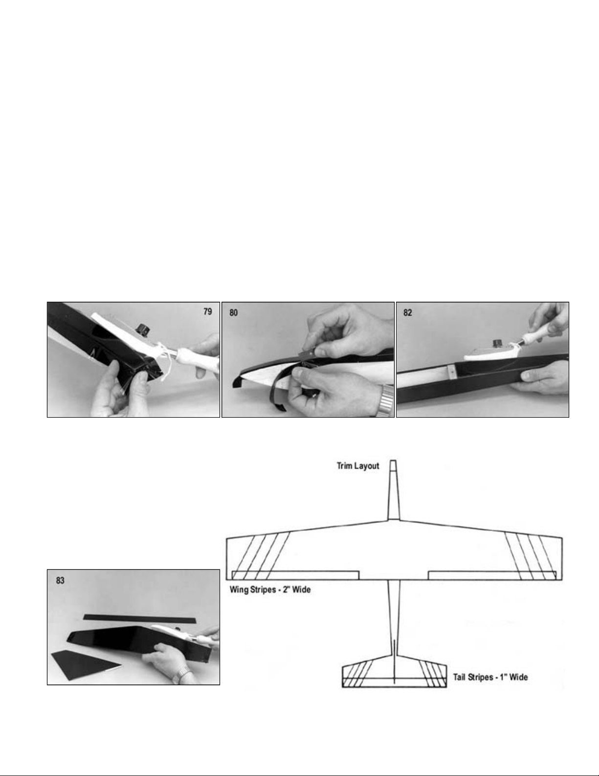
73.
be clean, dry, and dust free. Wipe the
entire surface with a tack rag or a cloth
dampened with alcohol to remove all
excess dust.
Select A Covering
because of its light weight and ease of application.
The color scheme that is pictured on the label is quite easy to duplicate and only requires two rolls of Sig Supercoat
Covering. The colors needed are two rolls of Black. In addition you will need one roll of Sig Supertrim Cub Yellow, one roll
Dark Orange, and one roll Waco Red. The canopy was covered in Silver, however any contrasting color can be used and
still have the same effect.
-on Plastic Covering. Supercoat is ideal for slope soarers
BUILDER'S TIP:
Before starting the actual application
of the covering material, use your
wife's or mom's (ask first) favorite
vacuum cleaner with the soft brush
attachment and vacuum the entire
model and the work bench. This
greatly helps eliminate the dust
particles tnat get under the covering.
necessary, but is a personal preference. A sock helps eliminate the unsightly small scratches that can be caused from the
dragging the iron across the surface of the covering material. We also highly recommend that you use a temperature
74.
edges, including the insides of the wing
tip and torque rod assembly, with 1/2"
strips of covering material cut from the
roll.
75. Cover the ends of the wing tips making
sure to run the covering material
"around the corner" about 1/8".
76. Cover the bottom of the wing first and
front seam overlapped on the bottom
to size, allowing approximately 1"
excess around the edges. Lay it down
and smooth out as many wrinkles as
possible.
Using your hot sealing iron, carefully iron the covering material from the center of the wing panel out towards the wing tip,
and then out towards the wing root. This is to help avoid trapping air bubbles under the covering. Work slowly and allow
Page 15
.
77.
Trim off the excess covering material leaving a 1/8" overlap at the trailing edge. Seal the overlap down with an iron.
Repeat the process from steps 74 through 78 to finish covering the other wing panel.
Covering The Fuselage
As the covering becomes pliable from the heat, you can pull it gently around the curve. Work slowly, allowing the heat to do
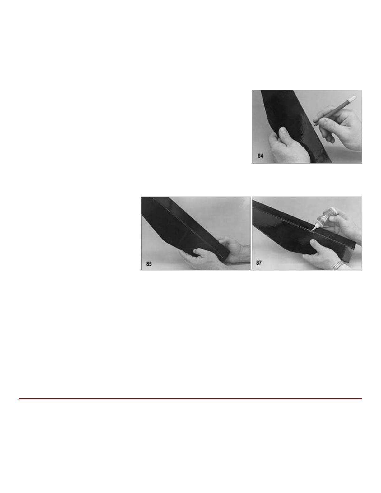
the work. Do not pull too hard or the covering might tear.
80. Trim off the excess covering material with a sharp single
-
edge razor blade and reseal the edges with the iron.
82. Cover the fuselage top in the same manner as the bottom and sides. Remember to reseal the edges after trimming.
Covering The Tail Surfaces And Ailerons
78. Cover the top of the wing in the same manner as described in the above steps 74 through 76. Leave a 3/16" overlap of
covering material on the leading edge of the wing and seal it down with an iron.
79. Cover the bottom of the fuselage first. When cutting the material for the bottom allow enough extra material around the
nose, or any other area with compound curves, so you can get a good grip on it with your hand. Start by sealing the
covering to the model at the tail. Work slowly forward with the sealing iron, sealing the covering smoothly to the bottom of
the fuse. When you get to the nose area, work the iron over the covering with one hand while you pull on it with the other.
81. Repeat this procedure for covering both sides of the fuselage. Allow about 1/8" to 1/4" overlap onto the top and bottom of
the fuse.
83. The stabilizer, elevator, ailerons, and fin
should each be covered with two pieces
of material - cover each side separately.
Iron the material from the center out to
avoid trapping air bubbles. Once the
ailerons have been covered, cut away
the material to expose the slot and hole
for the torque rods.
Page 16
.
Installing Easy Hinges
size plan for the exact hinge locations.
After all of the slots have been cut, insert EASY HINGES halfway into the
as small as possible but big enough to allow full movement of the control surface.
After the glue has cured (3 to 5 minutes) the joint should be flexed to full deflection in each direction a couple of dozen
HINGES halfway into the ailerons only. DO NOT GLUE THE HINGES YET!
Set epoxy glue to the slot and hole in the aileron leading edge, and then slide the aileron onto the torque rod, working
Once the epoxy has dried, remove the wax paper and apply thin C/A to the EASY HINGES, in the same manner as you did
FINAL ASSEMBLY
knife or a single
-
edged razor blade and don't cut too deep into the wood.
Sig's famous EASY HINGES have been included in your kit to hinge all the control surfaces. Each ultra-thin hinge is
actually a three-part laminate, a tough plastic inner core sandwiched by an absorbant wicking material on each side. They
are specially designed to be installed with thin C/A glue. The hinges have been chemically treated to slow down the set
time of the glue to allow it to soak all the way to the ends of the hinge and into the wood surrounding it, for a super strong
bond. Once the glue has dried, the hinge cannot be pulled from the structure without tearing wood out with it! We
recommend that all surfaces be completely covered before installing the EASY HINGES.
84. Use a #11 X-Acto blade (or similar) to cut slots in the stabilizer trailing edge and
elevator leading edge to accept the EASY HINGES. Make the slots
approximately 1/2" in depth and slightly wider than the hinges. Refer to the full-
85.
stabilizer slots. DO NOT GLUE THE HINGES YET! Next, carefully slide the
elevator onto the hinges. You'll find it easiest to slide the elevators onto the
hinges at an angle, one at a time, instead of trying to push it straight onto all the
hinges at once. Don't be concerned if the hinges aren't perfectly straight or
centered in the slots - they don't have a center line.
86. To set the hinge gap, deflect the elevator to the maximum amount needed. For best control response, the gap should be
87. Place three or four drops of thin C/A
directly onto the hinges in the gap. The
glue will wick into the slot as it
penetrates both the wood and the
hinge. Continue this process, gluing the
same side of all the EASY HINGES.
Then turn the stabilizer over and repeat
the gluing process on the other side of
each hinge.
88.
times to reduce the stiffness. Don't worry about shortening the life of the hinges, as they are almost indestructible.
89. The ailerons are hinged exactly like the tail surfaces, except that the torque rods must be glued in at the same time the
hinges are put in the slots. Start by cutting the slots in the wing and the ailerons (three per aileron) and slide the EASY
90. Next slide a small piece of wax paper between the torque rods and the wing. Working with only one wing at a time, apply
Kwikthe EASY HINGES into the wing slots at the same time. Try not to get any epoxy on the brass tubing! Before the glue sets,
be sure to deflect the aileron back and forth to set the proper hinge gap.
earlier for the elevator.
Bolt the wing in place and then position the stabilizer on the stab support at the back of the fuselage. Carefully align the
stab with the wing. Refer to the alignment drawing and carefully align the stab with the wing. When satisfied with the
alignment, draw cut lines on the bottom of the stabilizer at the fuselage sides. Cut away the covering on the bottom of the
stab where it will be glued to the fuselage (there must be wood to wood contact in the glue joints). Use a sharp modeling
Page 17
.
wing. Use pins to hold the stab securely in position until dry.
A 1/2"x12" strip of ABS plastic is
Completing The Elevator Pushrod
A small nylon control horn has been supplied for the elevator. Install the control horn onto the elevator with #2 x 1/2" sheet
metal screws.
inner pushrod.
pushrod tubing. Unhook the nylon R/C link from the control horn, and push the inner pushrod forward towards the servo.
Then put a "Z" bend (or a ''L" bend if you are going to use a pushrod keeper) in the non
-
threaded end of the rod.
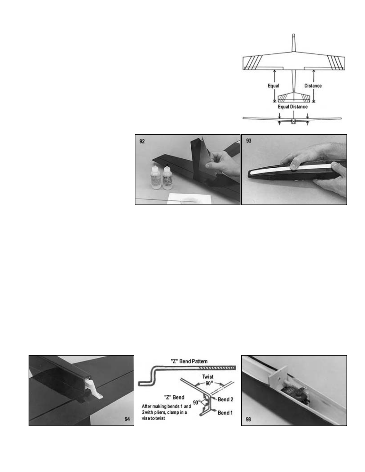
91. Glue the stab in place onto the fuselage. Use slow drying epoxy (SIGEG001) to
allow you ample time to carefully realign the stabilizer with the fuse and wing.
Check and double check the final alignment of the stab to the wing from the front
and top before the glue dries. Step back about 10 feet and view the model from
the front. Tilt the stab for proper alignment if necessary. Use a tape measure to
make sure the stabilizer tips are at equal distances from the trailing edge of the
92. Cut away a 1/8" strip of covering material from the center of the stabilizer where
the fin is to be glued. Epoxy glue the fin onto the stab and into the die-cut slot in
the fuselage top at the same time. Use a 90 deg. triangle to align the fin with the
stabilizer, pin securely in place, and allow to dry.
93.
provided for a landing skid. Round the
two front corners of the strip with a
sanding block. Apply double-coated
foam servo mounting tape to the plastic
skid, remove the paper backing from the
tape, and press the skid into place.
NOTE: The ABS plastic skid can be
painted a matching color with either
enamel or dope.
94.
95. To complete the installation of the nylon elevator pusnrod, first cut one of the 2-56 x 10" threaded rods provided to 3-1/2"
overall length, measuring from the threaded end. Slip the rod completely into the inner pushrod tube and then screw in
about 1/4" of the threaded portion. Screw the nylon R/C link onto the rod leaving a gap of about 1/8" from the end of the
96. Slide the 1/8" o.d. nylon inner push rod tubing into the outer tubing from the elevator end of the fuselage and attach it to the
nylon control horn. With the elevator level, cut off the protruding end of the inner pushrod 3/8" from the end of the other
97. Locate and cut one of the 2-56 x10" threaded rods provided to 1-1/2" overall length, measuring from the threaded end.
98. Screw the threaded end of the wire approximately 1/4" into the 1/8" o.d. nylon inner push rod tubing. Install the "Z" bend
through the servo arm and hook it up to the servo and reconnect the R/C link to the elevator control horn. NOTE: It may be
necessary to trim the servo arm down to prevent it from rubbing on the side of the fuselage.
Page 18
.
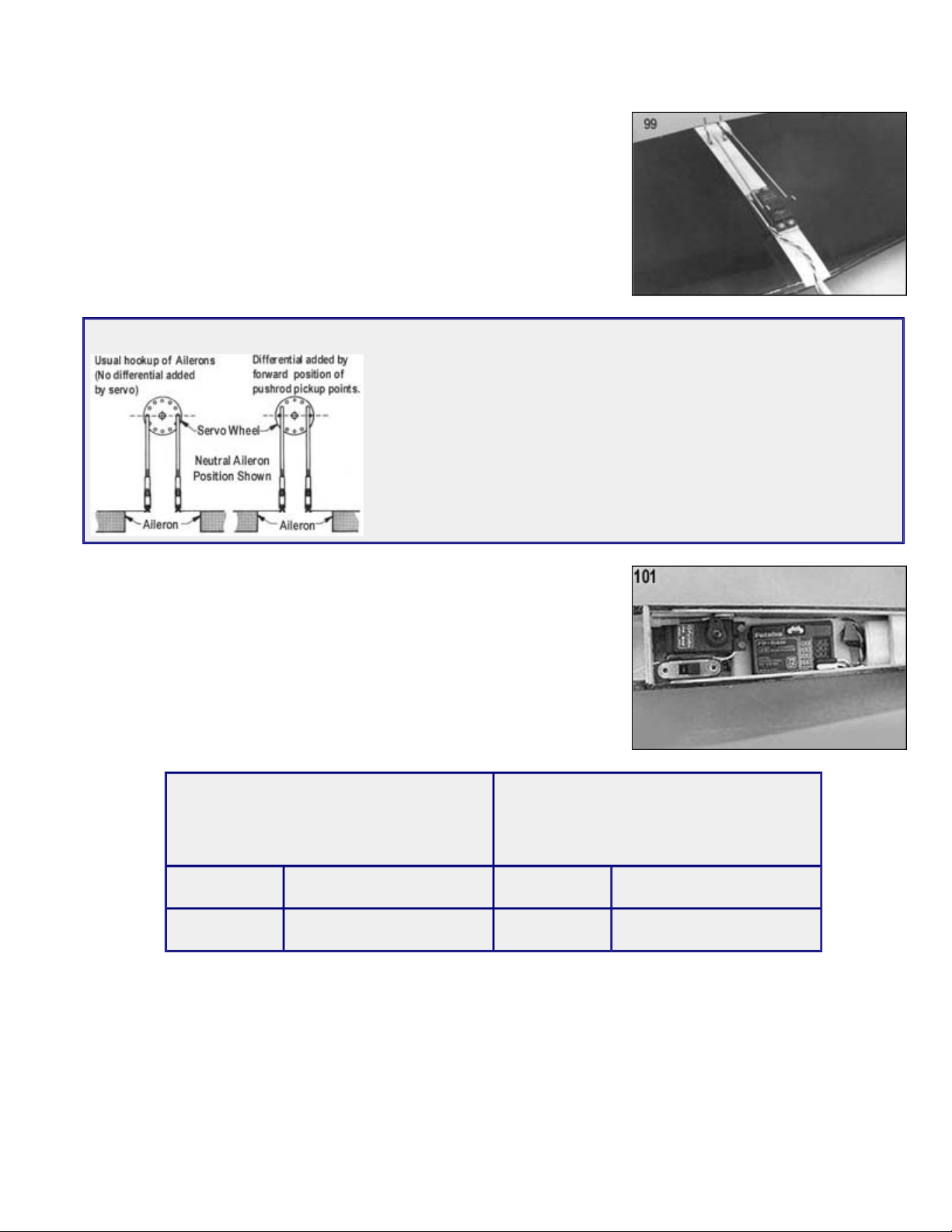
Aileron Pushrods
Mount the aileron servo to the hardwood rails in the manner recommended by the
and the ailerons level, measure 1/2" past the servo arm and cut off the wire. Put a
arm.
A typical 2 channel radio installation is shown in the photo. The battery pack and
assembly, (1) SIGSH220 short nylon control horn, and (2) EASY HINGES.
99.
radio manufacturer.
100. The aileron pushrods are made from two 2-56 x10" threaded rods. Screw a nylon
R/C link onto the threaded end of each rod. Next screw the self-threading nylon
aileron connectors that are provided 1/4 of the way down the aileron torque rods
that are sticking out of the wing. Snap the R/C links into the aileron connectors
and line up the pushrods with the servo arms. With the aileron servo neutralized
"Z" bend in the end of the rods and install them in the outside end of the servo
OPTIONAL AILERON SERVO HOOK UP
The aileron horns are offset for differential movement as much as is practical
without striking the fuselage structure during movement. Some of this offset is
cancelled out when the adjustable nylon fittings are added. The best way to
increase the amount of differential in the ailerons is by offsetting the pickup
points on the servo for the push rods as shown in the accompanying
drawings. Any amount desired can be obtained in this manner. The farther up
the wheels the pushrods are attached, the greater the differential, ie., more
up. less down movement.
Radio Installation
101.
the receiver are lightly packed in foam rubber and positioned just forward of the
elevator servo. The switch harness is servo taped to the fuselage side just
opposite the elevator servo. This allows the radio system to be easily turned on
and off by removing the quick release hatch.
Recommended Control Surface Movements
The following control surface movements are
recommended for initial flight tests and for
newcomers to the sport of R/C slope
soaring.
ELEVATOR 3/8" UP and 3/8" DOWN ELEVATOR 1/2" UP and 1/2" DOWN
AILERONS 1/2" UP and 7/16" DOWN AILERONS 9/16" UP and 1/2" DOWN
For the accomplished pilot and for all out
aerobatic performance the following
movements are suggested.
Optional Rudder
There may be some of you, especially veteran slope fliers, who will want to modify the Ninja from two channels (aileron
and elevator) to three channels (aileron, elevator, and rudder) for increased aerobatic performance. The hardware that is
provided in the kit is for the two channel version only.
To convert the Ninja to three channel operation you will need the following items, (1) SIGSH568 30" nylon pushrod
Page 19
.
2 for 3/16". Cut the outer push rod tubing oft flush
with the top of the fuse.
105. Hinge the fin and rudder with EASY HINGES.
After the fin/rudder assembly is glued in place on the fuselage and properly aligned, install a small molded nylon control
rudder servo and pushrod installation on the opposite side of the fuse.
108. Adjust the control throw of the rudder so that you have minimum of 3/4" left and 3/4" right of movement.
Balancing
balance point any further back than the rearward C.G. limit.
which wing panel falls. Add very small amounts of weight to the opposite wing tip
until it will balance. NOTE: Small finishing nails pushed into the end of the wing tip
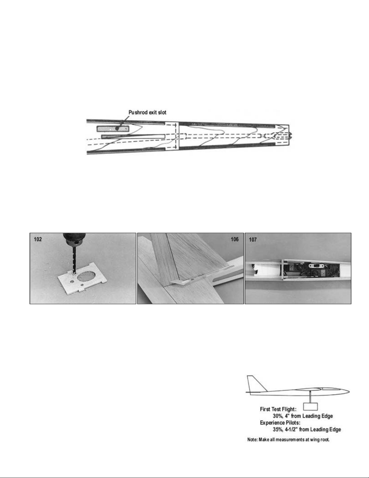
102. Drill an additional 3/16" hole in the opposite side of fuselage former F-2 to accept the outer nylon push rod for the rudder.
NOTE: The fuselage construction must be completed through step 66 before proceeding.
103. Cut a slot 3/16"x1-1/8" in the fuselage top for the outer nylon push rod tubing to exit through, as shown in the diagram.
104. Install the 3/16" o.d. outer nylon push rod tubing (SIGSH568) for the rudder by passing it through the pre-drilled hole in
former F-2 and the diecut notches in formers F-3, F-4, and the push rod exit hole in the fuse top. Epoxy glue the outer push
rod tubing in place at each of the fuse formers and to the fuse top.
NOTE: Make sure that the outer push rod extends out in front of former F-
106.
horn (SIGSH220) onto the rudder with two #2 sheet metal screws.
107. Refer to the elevator servo and pushrod installation procedures elsewhere in this book for guidelines on completing the
Make a balancer from a block of wood and two pencils that are tipped with erasers. Drill two holes in the block of wood
about 3" apart and install the pencils. To check the fore and aft balance of your model, mount the wing on the fuselage and
place the model in the balancer. The fuselage side view plan shows two locations for balancing the Ninja. The forward C.G.
location is best suited for the first test flights and newcomers to the sport of R/C slope soaring. The rearward location is for
more experienced pilots. The rearward C.G. makes the Ninja more sensitive to control movements, improving it's aerobatic
ability. Balance the Ninja within the recommended C.G. range to suit your needs. Do not attempt to fly the model with the
The spanwise balance of the wing is an often overlooked but essential part of
balancing a model. Check the spanwise balance of the wing by placing the wing
upside down on the balancer. Hold the wing level and then release it, observe
are ideal for this.
Page 20
.
Pre-Flight
everything is 100% correct.
First Test Flight
with.the model, then release it with a smooth spear
Aim for a spot on the ground about 50 yards out ahead of you. The
After each test flight, readjust the R/C links on the push rods so that
throughout the country.
Finding a Hill
"bowl" created by either a curved hill or by a series of hills.
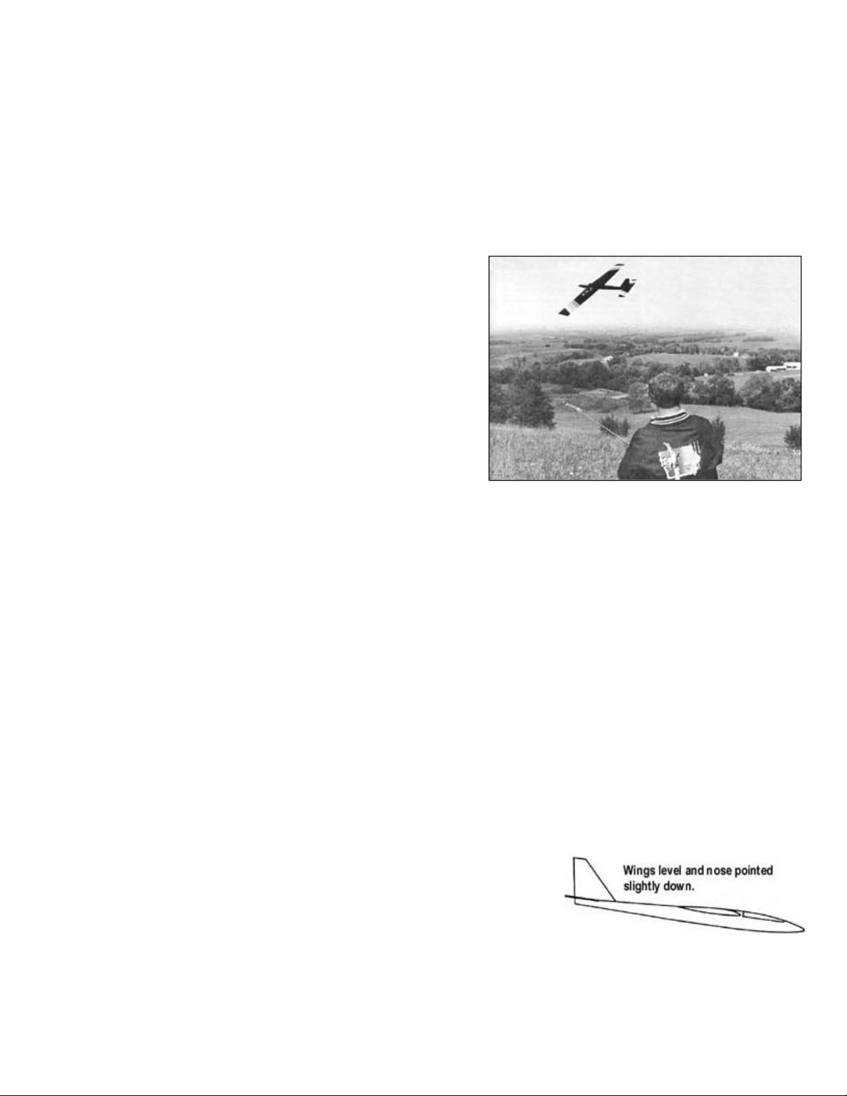
Flying Tips For The Novice Slope Soarer
wings level and nose pointed slightly down. Let the model travel out a little ways
gain.
Make sure the servos are securely mounted, the servo arms have their retaining screws in place, and all screws are tight.
Range check the radio as per the manufacturer's instructions and make sure it is fully charged. If there are any problems,
send the radio in for repairs.
DOUBLE CHECK EVERYTHING YOU CAN THINK OF! A model and radio that is not prepared and working properly on
the ground before take-off will not improve in the air - IT WILL GET WORSE! There is no point in attempting to fly until
Choose an area that is free of obstructions such as buildings and
trees, and pick a day when there is little or no wind. If your flying site
is occupied by other fliers, check with them to be sure that your
frequency won't interfere with theirs, and vice-versa.
Gently hand toss the glider into the wind with the nose pointed
slightly down and the wings level. Start by running a couple of steps
-throwing action.
Ninja should glide smooth and flat with no veering to the left or right.
the trim levers on the transmitter can be returned to a neutral
position. It may take several flights to completely trim out the model.
Introduction To Slope Soaring
Slope soaring offers a unique brand of flying excitement not found in other types of R/C model flying. From flying lazily
along with a floater, to breathtaking high speed beach runs, slope racing, and aerobatics, there is something for every skill
level of pilot. Besides being a lot of fun, how many other model pilots do you know who want the wind to blow?
It is easy to see why slope soaring is fast becoming one of the most popular parts of R/C soaring. Slope soaring is no
longer limited to just the east and west coasts. As the popularity of slope soaring grows, more flying sites are turning up
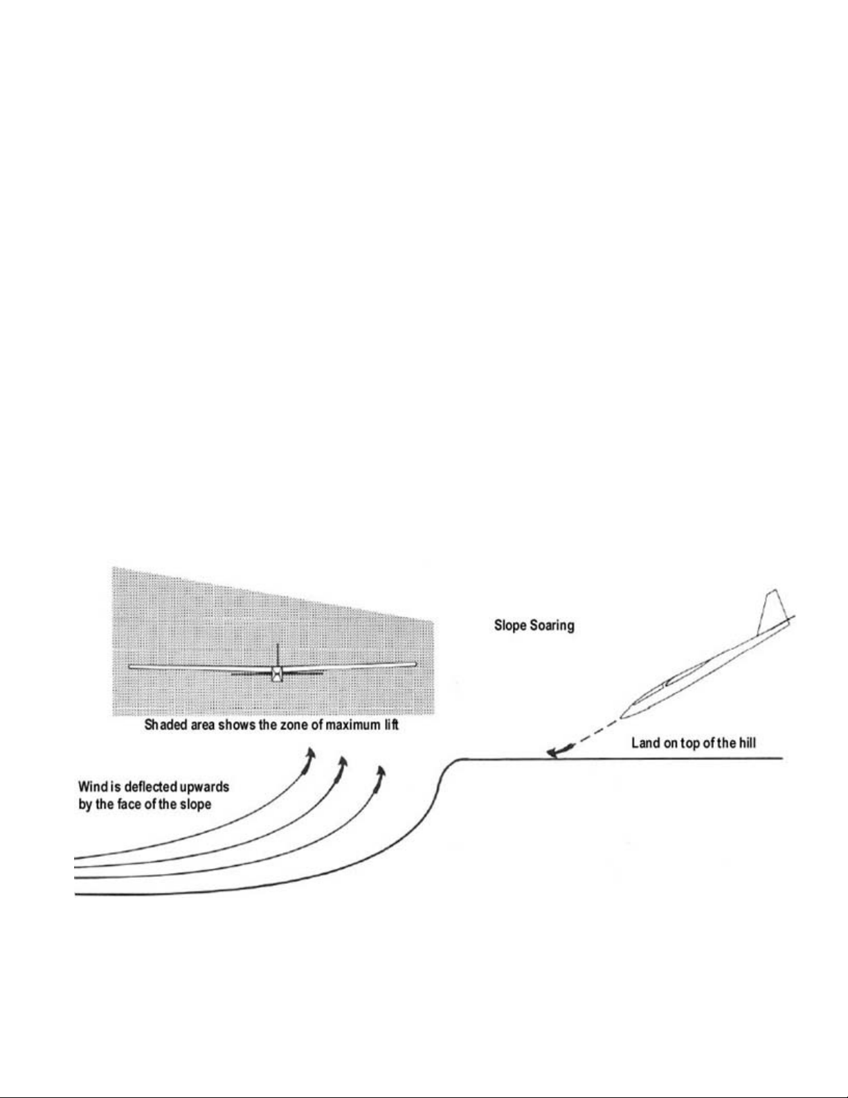
Wherever you can find a respectable-sized hill with a 10-20 m.p.h. wind blowing straight into the slope, you can slope
soar. The wind is deflected upward by the slope of the hill creating the lift we soar on. The amount of lift generated by a
particular hill is regulated by the wind velocity and the amount of slope in the hill. Also a hill that has a smooth approach to
it (free of trees, buildings and etc.) will almost always produce stronger lift. Don't overlook places like dams, reservoirs,
bluffs overlooking lakes and river valleys. They all make good flying sites. The ideal slope site is one in which there is a
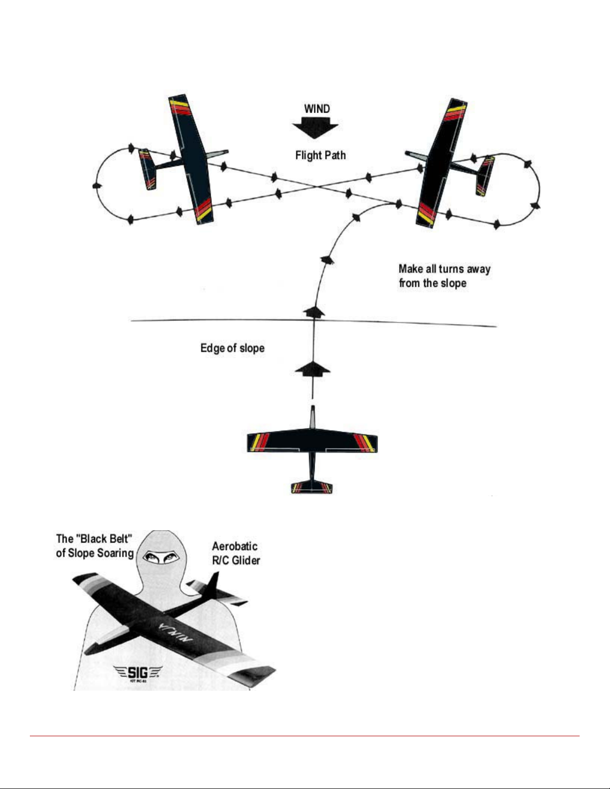
Launch the Ninja into the wind out over the crest of the hill by throwing it with the
to build up speed and then make a turn that brings the flight path of the model
parallel to the slope. When you need to turn the model around, make your turn
into the wind away from the slope and again fly parallel to the slope. Repeat the
above procedure when it is time to turn again. Flying this flattened figure eight
coarse back and forth across the face of the slope is standard procedure. This
helps keep the model in the maximum lift zone which yields the most altitude
Page 21
.
Ballast
adding ballast. Simply press them in place inside the fuselage directly over the C.G.
Aerobatics
maneuver in the book and then some.
up with any, new ones, let us know.
Landing
this site.
Flying Off A High Start Or Winch
strong lift, it is possible to thermal the Ninja with flights lasting over 15 minutes.
The clean lines and the low frontal area of the Ninja allow it to penetrate winds in the 10-20 m.p.h. range without ballast.
However, when flying in winds of excess of 20 m.p.h. some ballast may be needed. Stick-on lead weights are ideal for
Slope soarers don't have engines to pull them through aerobatic maneuvers like power models do, so we have to rely on
the lift and the speed of the model to perform aerobatics. Always pick up speed by diving the model before entering a
maneuver. The amount of speed required, depends on the maneuver and the available lift. If you are new to slope soaring
make your maneuvers into the wind at first until you feel comfortable. Aerobatics with the Ninja are a snap. It will do any
When the Sig Factory Fliers go to the slope, we have a blast making up new aerobatic "maneuvers" on the spot. For
instance, how about our death defying "Chicken Immelman" - start by diving straight at the hill, wait until the last possible
second, then pull up into a quick half loop and roll out at the top. Crazy, but not boring! Or how about a "Reverse
Corkscrew" start real high, dive straight down (We mean straight!!!), performing two aileron rolls on the way down. Then
quickly pull the airplane straight up! Try to get in two more rolls before running out of airspeed. Tons of fun!!! If you come
To make a landing approach, start with a fair amount of altitude, then fly the model slightly behind the crest of the slope,
and try to fly a steady descending path right down to a landing on top of the hill. If you are too high on your landing
approach, make S-turns to lose altitude or go around and try it again. Most slope soaring sites create an air turbulence on
the back side of the hill. Avoid getting caught in this turbulence as it might cause you to lose control of your model and
crash.
NOTE: When flying at established sites, check with the local flyers to determine what is the best approach for landing at
Launching the Ninja from a high start or winch is as simple and straight forward as launching any sailplane. Although most
of the flights are short in duration, they can be quite exciting while doing loops, rolls, inverted flight, and other aerobatic
maneuvers. Install a tow hook in the bottom of the fuselage 3-1/2" back from the fuselage former F-2. During periods of
Page 22
.
wind blows, grab your Ninja and head for your favorite slope.
SIG MFG. CO., INC............Montezuma, Iowa 50171
-
0520
It will take a little practice to master the art of slope soaring, but it is well worth the effort and a lot of fun. So, next time the
© Copyright SIG Mfg. Co., Inc.
LIMIT OF LIABILITY:
In use of our products, Sig Mfg. Co.'s only obligation shall
be to replace such quantity of the product proven to be
defective. User shall determine the suitability of the
product for his or her intended use and shall assume all
risk and liability in connection therewith.
 Loading...