

Page 1
The Kadet Senior basically follows the philosophy of our other models in the
will not be suitable for aileron control and in fact, does not need it. The excellent
is not to choose between the Senior and the Kadet MKII, for example, but to make use of both. Start with the slower Senior to
RADIO EQUIPMENT REQUIREMENTS
channels. This would eliminate the necessity of disposing of an initial investment in beginner's equipment of less than 4 channels
cells. Nicads are safer, since you go out flying with a full charge and don't have to worry about losing control from dead batteries.
Kadet Trainer series that preceded it, a stable, high wing design using a flat
bottomed airfoil. The major difference is that the wing loading has been reduced
by increasing the size and simplifying the structure. It is more of a "hands off"
flier because of increased dihedral and larger tail surfaces, but because of this,
performance is mainly a result of the light weight, but because of this, the Senior
cannot be as rugged as the Kadet Jr. and MKII. The Senior should not be flown
in winds over 10m.p.h. or in a field with obstructions to run into, or from a bad surface that will cause cartwheels on landing,
until you are a proficient pilot. The Junior and MKII are best for rough flying conditions. But the best approach, in our opinion,
develop confidence and automatic reactions. Then go on to the Kadet Mark II for graduation to aileron control. The only
transition between the two airplanes is minor, which can be quickly by-passed with a little ground taxiing experience to get
used to steering the nose with a different hand.
Selection of radio equipment should be based on the amount of money you wish to spend, the type of airplanes you intend to be
flying and your future goals. If you plan to stay in the hobby and work up to larger airplanes with complete controls, it might be
best to consider the purchase of a four, or more, channel set in the beginning, even though the model is flown on fewer
and buying a new set when your flying skills are ready for an advanced model. Equipment with nicad rechargeable batteries is
strongly recommended. Dry cell operation is cheaper initially but the money saved is soon wiped out buying replacement dry
Page 2

.
ENGINE SIZE
oversize engines may overload the airframe. Remember that a muffler will reduce engine power and allowance should be made
for this. If you live at high altitude, engines will not develop power equivalent to that delivered at sea level.
ABOUT THE BUILDING SEQUENCE
wing and tail saddles on the fuselage and align them to each other. The way to understand these relationships is to read these
to right or left as if seated in the cockpit.
REFER TO "THE BASICS OF RADIO CONTROL"
SOME BUILDING SUGGESTIONS
building board, into which pins can easily be pushed. Lay the building board on a table with a flat and untwisted top. Pins can be
will fill up during sanding and doping. Use Sig
single edge razor blade is best for cutting sticks. Use a modeling knife for cutting out sheet balsa parts.
INSPECT THE WOOD
Though we try to eliminate spar wood with flaws, there is always the possibility of a too soft spar or one with an imperfection in a
section and the first two rib bays on the outside of the cabin.
USE ENOUGH GLUE
wing spar webs.
A caution about cyanoacrylate glues. The thin glues are handy for instantly assembling a structure. However, unless the joints
are perfectly fitted, they are able to fail later. Therefore we recommend that you go over all joints that have been assembled with
We are of the opinion that RC trainers should have adequate power for such things as grass field takeoffs, beating their way
upwind, etc. Therefore fairly large engines are recommended. For cruising around and learning to fly, throttle back with the
knowledge that power is available when needed. Engines larger than those listed on the box lid are not recommended. Use of
The quickest and most efficient way to complete a model is to work on several pieces at the same time, such as the front and
rear of the fuselage. We occassionaly get suggestions that our instruction guides should be in exact step-by-step building
sequence. But this would result in many sentences starting, "While the glue is drying on the fuselage, move to the wing ...etc."
and a lot of jumping back and forth between assemblies with no consistant pictorial progression. Also, a pre-selected building
sequence by our choice might not suit your workshop space and time allotments. Therefore we feel the present system of
covering main assemblies in a unit works out best for the majority of kit builders. So keep in mind that the numbering sequence
used in this guide was chosen as the best way of explaining the building of each major assembly and is not intended to be
followed on exact one-two-three fashion. Start on the wing at No.1 and after doing as many steps as convenient, flip over to the
next main heading "FUSELAGE CONSTRUCTION" and do a step or two there, then over to "TAIL SURFACES" and so forth.
You will, of course, arrive at points where you can go not farther until another component is available. For example, you need a
nearly completed wing before the fuselage can be entirely completed. And you will need both the wing and the stab to fit the
instructions completely and study the full size plans before beginning to work. Think ahead! Any reference to right or left refers
In addition to the instructions you are reading now, the publication "The Basics of Radio Control" has been included with this kit
as a reference for installing the engine, fuel tank, and radio in the Kadet Senior. It also contains very important information on
preparing the model for flight. Modelers of all experience levels are encouraged to read this publication and follow its guidelines
for success.
Cut all long pieces of balsa first, followed by medium lengths, before cutting up any full-length strips into short pieces. Protect
the plan with wax paper or plastic wrap under the assemblies. A piece of Celotex-type wallboard or foam board makes a handy
pushed through all pieces in the kit without any lasting damage. Don't be afraid to use plenty of pins when planking. The holes
-Bond glue for general construction except where the instructions call for epoxy. A
critical place. Double check the wing spar wood before building it into the wing. The most critical part of the wing is the center
The thousands of Kadet Senior and Senioritas flying are proof of the adequacy of lightweight structure when properly
constructed. But the model will not be strong if you skimp on the glue. This is particularly true of the central area of the wing.
The doublers must be glued to the spars with full glue coverage. The same thing applies to the plywood spar braces and to the
a thin cyanoacrylate and make an external fillet of thick cyanoacrylate.
Page 3
.
YOU CAN'T GET ALONG WITHOUT A GOOD SANDING BLOCK
the parts together or carving to shape. Don't force die cut parts from the sheet. Use a modeling knife to finish freeing them.
1/4"x30" Fuselage Bottom Sheeting,
Wing Center Sheeting Rear, Wing Spar Webs,
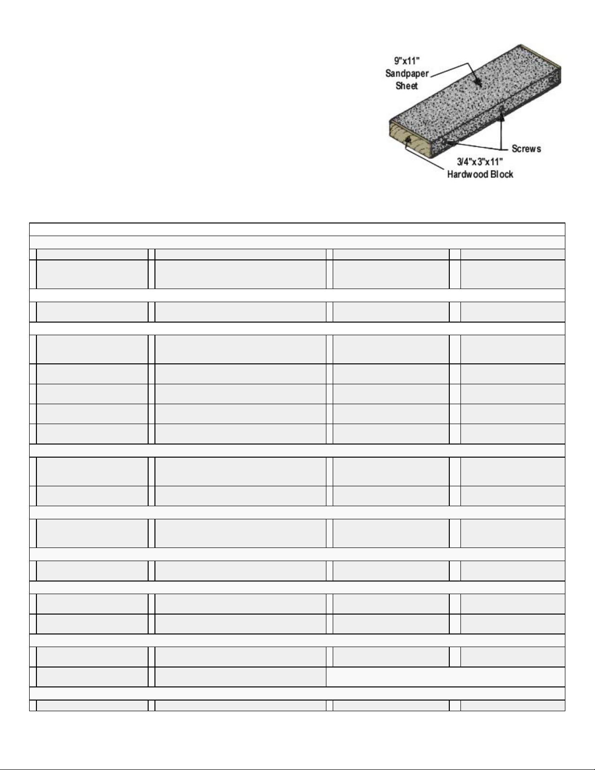
An indispensable tool for proper construction is a large sanding block, sized to
take a full sheet of sandpaper. Use several wood screws along one edge to hold
the sheet in place. Use the block to bring all parts and sticks to final, exact fit. I
recommend 80 grit garnet paper for use on the block during general construction.
You can switch to 100 grit, followed by 220 silicone paper for that finish just
before covering. In addition to the large block, there are places where a smaller
one is handy. Also a sandpaper "file" can be made by gluing sandpaper to a flat
spruce stick for working in tight-places.
LEAVE THE COMPLETE BLACK LINE ON THE PRINTED PARTS! A modelling
knife or jig saw can be used for cutting out the printed parts. Don't cut too close
to the lines - leave some extra wood outside the lines. True up and finish the edges with a sanding block as you are fitting
COMPLETE KIT PARTS LIST
Die-Cut Balsa Sheets
2 Sheet No.4 Ribs W-1 3 Sheet No.5 Ribs W-2 6 Sheet No.6 Ribs W-3 1 Sheet No.7 Ribs W-4
1 Sheet No.9 Elevator &
Rudder Ribs E-1, E-2, R-1
thru R-7
Printed Balsa Sheets
1 Sheet No. 1 Fuselage Parts
FN, G-1, G-2, G-3
Stick Balsa
2 1/2"x1/2"x36" Wing Leading
Edge
1 3/8"x3/8"x12" Stabilizer
Frame
3 5/16"x5/16"x36" Fin Frame,
Pushrods
1 3/4"x15" Triangular Stock
Firewall braces, Cowl Front
1 1"x4-3/4" Traingular Stock
Windshield Fillet
Sheet Balsa
2 3/32"x4-3/4"x24" Fuselage
Side Sheets
1 5/16"x1-1/4"x4-1/4" Fin
Fillet FD
Special Shaped Balsa
1 3/16"x3/4"x30" Elevator
Trailing Edge, Notched,
Shaped
Die-Cut PlyWood
1 1/8"x3-1/2"x11" Lite Ply FT, FF2 1/64"x4"x11-7/8" Birch Cabin Window
Hardwoods
2 1/4"x6-1/2" Wing Dowels 1 3/8"x1"x4-1/8" Grooved Hardwood Block 2 3/8"x3/4"x1" Landing Gear
1 3/8"x3/8"x9-1/2" Servo
Mounts
Spruce Sticks
2 1/4"x1/4"x22" Fuselage
Frame Top
1 1/8"x3/8"x4" Stabilizer Brace 2 1/4"x1/2"x16" Front Top Wing Spar Doublers May be furnished as 2 15-1/4" long Cabin Tops and 2 36" long
Wire Parts
1 1/16"x9" Pushrod Ends 1 5/32" Formed Nose Gear 2 5/32" Formed Main Gear
1 Sheet No. 2 Cowl C-1, C-2 1 Sheet No 3 WT, C-3 (Use
6 1/4"x1/2"x36" Front Wing Spars, Fuselage
Crosspieces
3 1/4"x3/8"x36" Elevator Leading Edge,
Diagonal Stabilizer Braces
1 1/8"x1/4"x24" Fuselage Rear Diagonal
Braces
1 1/4"x3/4"x3-3/4" FD 1 5/16"x5/16"x18" Fin Frame 1 1/2"x10" Traingular Stock
5 3/32"x3-
Fuselage Top Sheeting
1 7/16"x1-3/8"x36" Left Wing Trailing Edge,
Notched, Shaped
Frames
1 5/32"x1-1/8"x1-5/16" Landing Gear Wedge 1 1/8"x7/16"x2" Ply Right
3 1/4"x1/4"x36" Cabin Top Stringers, Fuselage
Frame Bottom
scrap for Wing L.E. Center)
6 3/16"x3/8"x36" Rear Wing
Spars, Rear Bottom Spar
Doublers
1 3/8"x3/4"x9" Stabilizer Center 13 1/4"x1/4"x36" Fuselage
1 1/8"x5/16"x24" Fin Diagonal
Braces
1 1/8"x3"x4-1/2" Fuselage Fill-
in at Fin
1 7/16"x1-3/8"x36" Right Wing
Trailing Edge, Notched,
Shaped
1 5/32"x6"x5-3/4" Firewall PF
Anchor Blocks
Thrust Shim
5 1/8"x1/4"x8-5/8" Fuselage
Nose Stringers
Fuselage Bottoms
2 3/8"x3/8"x36" Stabilizer
Frame
Frame
1 3/16"x5/16"x24" Fin Ribs
Wing Leading Edge Fillet
2 1/16"x3"x18" Wing Tip
Sheeting
1 1/8"x3/4"x11" Rudder
Trailing Edge, Shaped
2 1/4"x3/4"x1" Basswood-
Wing Anchor Blocks
4 1/4"x1/4"x7-7/8" Cabin
Doublers
Page 4
.
#4x3/8" Metal Screws for Landing
WING CONSTRUCTION
plan.
a.
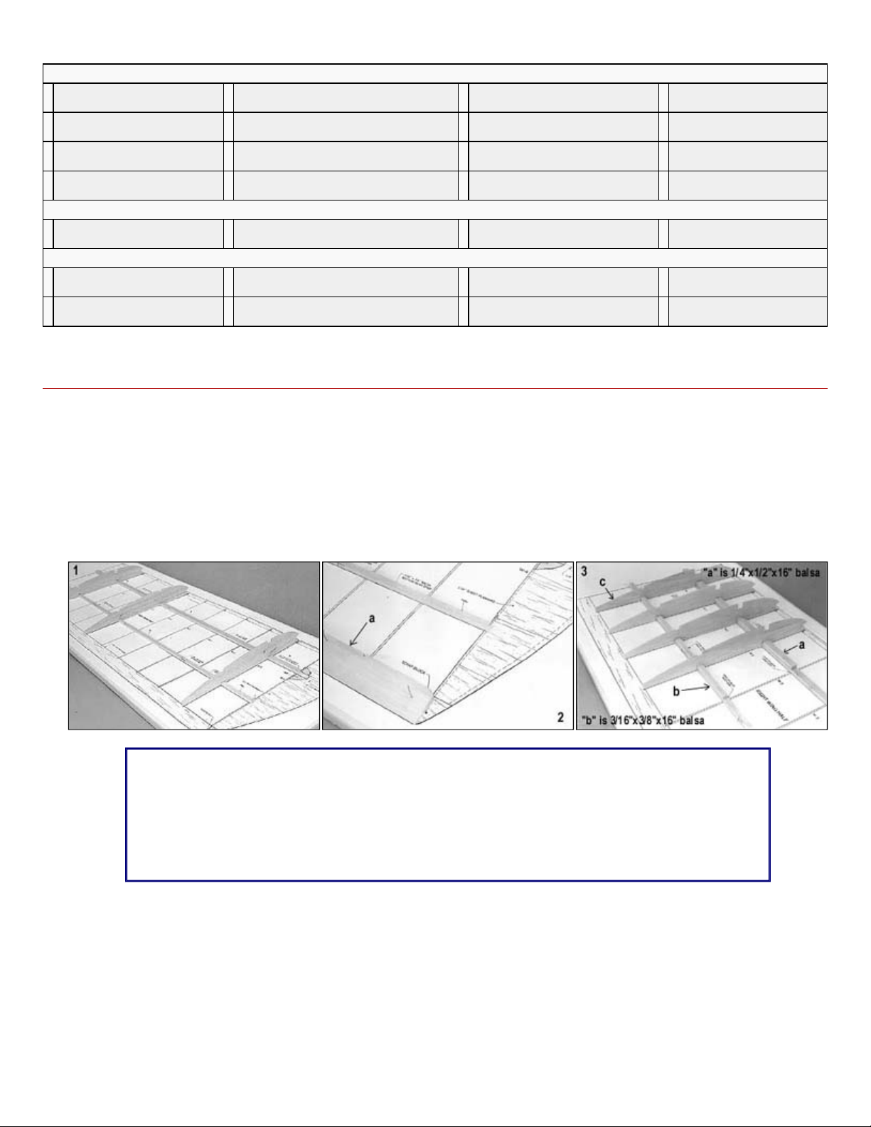
Pin down the notched wing trailing edge
c.
Begin gluing ribs in place, starting with the second W
-
1 rib. Do not glue the center W
-
1 in place until later.
Continue pinning and gluing ribs in place on the spars, working toward the tip.
b.
Glue a 3/16"x3/8"x36" top rear spar in place in the rib notches. The top rear spar has no doublers.
Hardware
1 5/32" Nylon Nose Gear
Bearing
2 Nylon Control Horns 4 4-40 Blind Nuts for Nose Gear Bearing 4 6-32 Blind Nuts for Engine Mounts 4 4-40x3/4" Screws for Nose
4 6-32x1" Bolts for Engine
Mounts
2 Glass Filled Engine Mounts 2 1/16"x3/8"x1" X-Large Landing Gear
1 5/32" Nylon Nose Gear Steering Arm 1 6-32x1/4" Screw for Steering Arm 1 Package of 7 Easy Hinges
Gear Bearing
4 No.2 2x3/4" Pan Head Screws for
Control Horns
Straps
2 2-56 RC Links 2 10" RC Rods
4
Gear Straps
1 Pushrod Connector
Assembly
Laser Cut Parts
2 5/32"x1-1/2"12-3/4" Dihedral
Doubler D-1
Miscellaneous
2 38"x50" Full-Size Plans -
Plates One and Two
1 3"x4-1/2" Decal - Kadet
Senior - 2 Color
1 28 Page Instruction Book 1 Basics of RC Book 1 2"x16" Fiberglass Tape
2 3-1/4"x10-3/8" .015 Clear Butyrate -
Cabin Side Windows
1 4-5/8"x10-7/16" .015 Clear
Butyrate - Windshield
1.
Using several ribs as guages, pin down a 1/4"x1/2"x36" front bottom spar and rear 3/16"x3/8"x36" rear bottom spar on the
2.
3.
a. Glue a piece of 1/4"x1/2"x16" Balsa on top of the front spar as a doubler.
b. Glue a piece of 3/16"x3/8"x16" balsa on top of the rear spar as doubler.
ABOUT TRAILING EDGE RIB NOTCHES
The rib notches may vary slightly in position on the plan because, as noted, the plan paper is subject
to shrinking or stretching with humidity changes. Therefore the rib may not sit perfectly on the rib
position on the drawing. Ignor this and simply make the rib parallel to the rib drawing. The notches also
tend to vary in depth and width. Take a die cut rib, draw a line on it 1/8" from the end and use this as a
guage to check the notch depth and fit to the rib. Enlarge any notches that aren't deep enough or wide
enough with a razor blade.
4.
5.
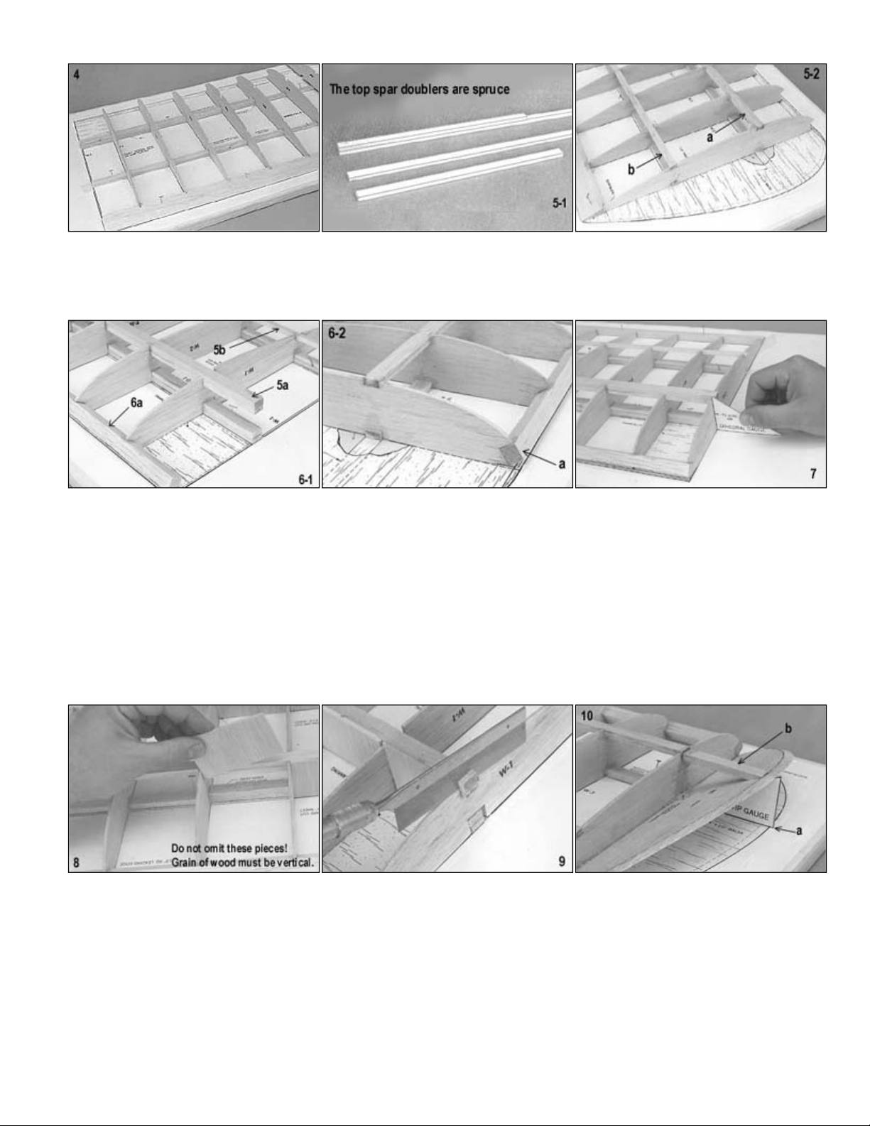
a. Prepare the 1/4"x1/2"x36" top from spar by pre-gluing a 1/4"x1/2"x16" spruce doubler in place. Then glue the
assembled spar into the rib notches
Page 5
.
Position the center W
-
1 rib, using the dihedral guage as shown to get it at the right angle. Tack glue only until paragraph 18.
the joint. (paragraph 18).
Glue the spar webs which are pieces cut from a 3/32"x3
-
1/4" sheet. Note that the grain is vertical.
Saw off the spar ends flush with the angled rib.
the stub spar.
peak of the 1/2" sq. leading edge.
a.
Glue a scrap block to the trailing edge and back of WT. Have it extend past WT to provide trimming room later.
6.
a. Glue the 1/2" sq. x 36" leading edge into the front of the ribs.
7.
NOTE: The Dihedral Guage is not a Micrometer. The final fit of the center seam should be made by checking and sanding
8.
9.
10.
11.
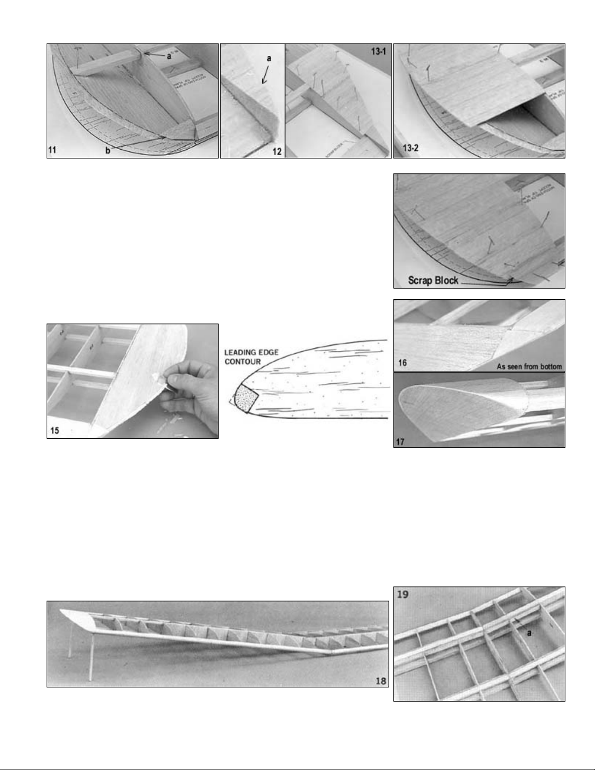
a. Using the wing tip guage, glue the pre-beveled wing tip WT in place.
b. Add the stub spar, a piece of 1/4"x1/2" spar stock. Note the wing tip cross-section on the plan, which shows this
piece to be recessed down from the top of the main spar so that the 1/16" sheet tip sheeting can be glued on over
a. Notch the main spar out 1/16" deep above the rib so the 1/16" tip sheeting will be flush with the top of the main spar.
b. Cut a piece of scrap wood to fit into the "V" formed by the wing tip WT. The front of the scrap is flush with the top
12.
13. Sheet the wing tip with 1/16"x3" balsa pieces. Allow them to protrude past WT to provide room for trimming as seen below
in 15.
Page 6
.
as you fine sand the root ribs as may be necessary to make them fit snugly together. Take a little time to get the fit right. We
edge faces.
a.
As soon as the wing is joined together, add the top 5/32" plywood spar doubler D
-1
20.
Turn wing over and sand the bottom 5/32" spar doubler D
-
1.
14.
Finish the front WT with another piece of scrap balsa.
15.
Turn the wing over and trim the top 1/16" tip sheeting off flush with the bottom of
WT.
16.
Trim the trailing edge block off as shown and sand and smooth.
17. Trim the leading edge block off as shown and sand and smooth. This shape is
determined by the trimming and rounding of the leading edge. However - do not
shape the leading edge at the center section until after the windshield fillet is
glued on later.
18. With one half of the wing flat on the table, raise the other half 6", measured at the bottom of the tip rib. The picture shows
and easy way to do this with two measured scrap pieces of wood tack glued to the tip. This allows easy moving of the wing
strongly advise drilling some 1/16" holes at slight angles about 1/4" to 3/8" deep, into the spar, leading edge and trailing
Use slow setting epoxy and work these holes full of glue with a wire. Then coat the faces of the spars. I.e. trailing edge and
rib roots, and join the wing halves together. The holes full of epoxy will "nail" the spars together.
19.
Page 7
.
wing as shown.
Turn the wing over and fit two more pieces of 1/2" triangular stock to the bottom in the same manner as the top. Trim off the
bottom triangular stock flush with the bottom surface of the windshield fillet.
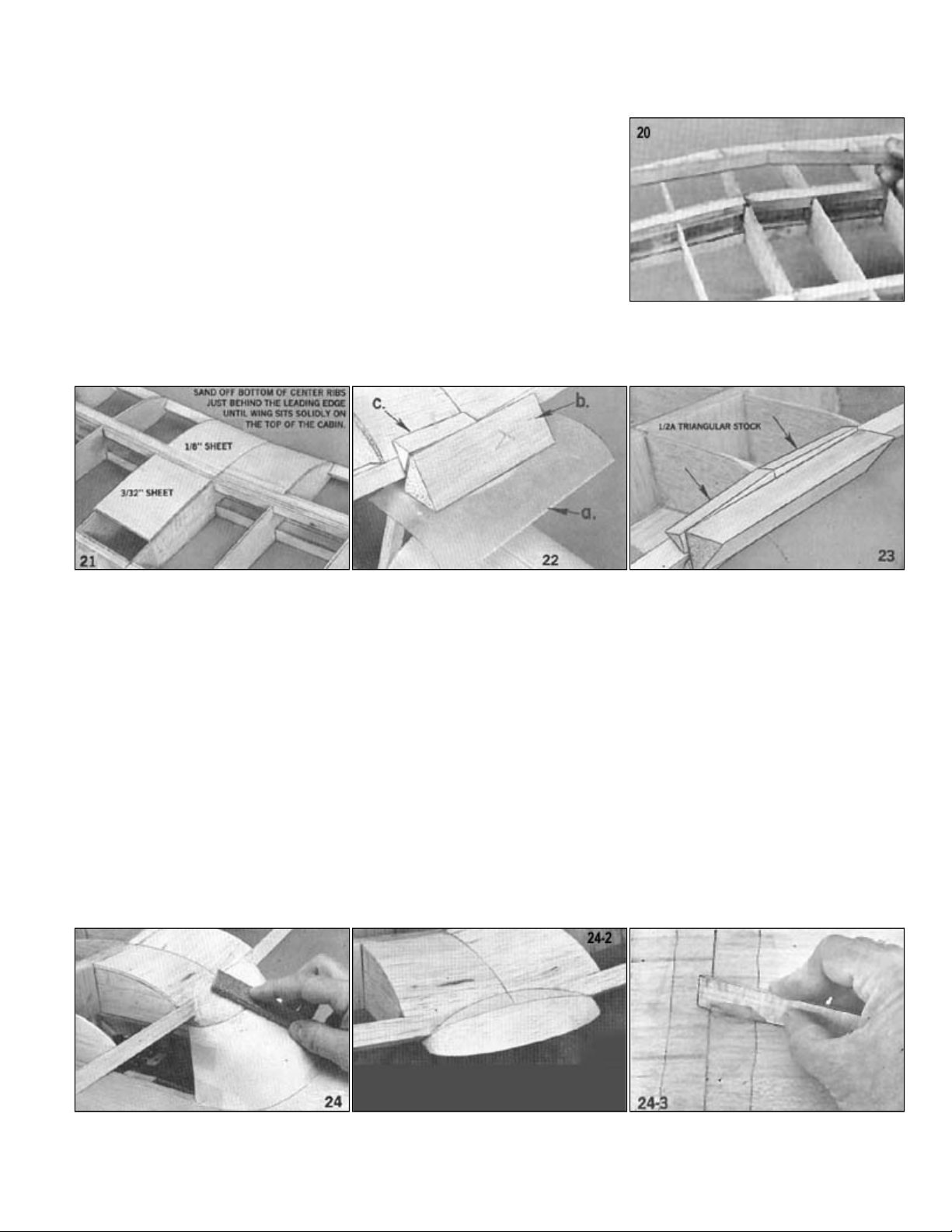
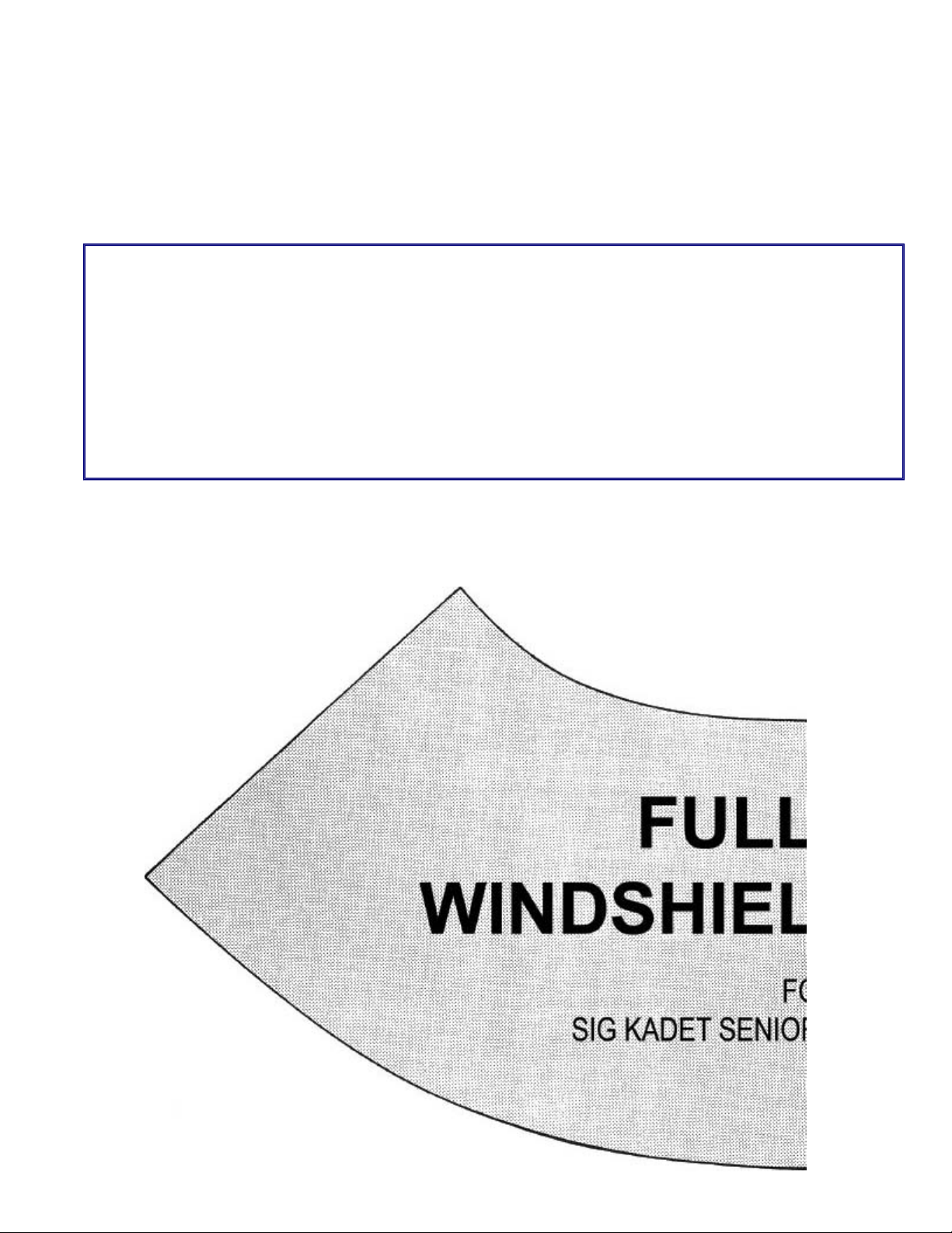
Glue the paper windshield pattern to light card stock (like a manilla file folder) and position it on the fuselage. Trim as
Carve the top of the windshield fillet block roughly to shape with a whittling knife, removing it from the fuselage top to
the windshield angle.
24/3
warm the mixing container by setting it in hot water for a few minutes to raise the temperature of the glue. But work quickly,
glue.
21. Cover the center section in front of the main spar with 1/8" sheet balsa. Cover the
remainder of the center section with 3/32" sheet balsa.
22. For this step you will need the fuselage completed up to the point of having
installed FF.
a. Lay a piece of wax paper on top of FF. Set the wing on the fuselage and
pin or tape it in place. You may need to sand the point of the dihedral joint
at the leading edge slightly to get the wing to sit solidly on the fuselage.
b. Sit the 1"x4-3/4" triangular windshield fillet block on FF and glue it to the
point of the unshaped leading edge.
c. Fit two pieces 1/2" triangular stock between the windshield fillet block and
the leading edge. Sand the face of them as required to fit snugly onto the
23.
24.
a.
necessary for a perfect fit. Tape it in place.
b.
do so.
c. Replace the wing on the fuselage and get the final shape with a small sanding block, bending the fillet contour into
The wing center joint is reinforced with the strip of 2" wide fiberglass tape. I use regular Sig Epoxy Glue (not Kwik-Set Glue)
for applying the fiberglass tape, since it is thinner and easier to spread out smoothly. It will be even easier to spread if you
for the glue will set up much faster than normally when warmed.
a. Coat the wing center with glue.
b. Lay the tape on top of the glue.
c. Holding one end of the tape so it won't slip, "squeegee" the glue through the tape, with a small paddle made from a
scrap of balsa. Scrap over the tape several times with the squeegee paddle to smooth the tape and remove excess
Page 8
.
FIREWALL ASSEMBLY
READ THIS SECTION CAREFULLY
will provide right thrust offset. Read this entire section. If you feel you understand the operational installation, use it to follow the
directions in that section. Otherwise , skip that part.
b.
Mark and drill the holes using a 1
-
1/64" drill bit for the 6
-
32 blind nuts.
32 blind nuts. These strips are cut from scrap ply off the firewall die cut wood. The strips are offset in picture
up. With the mounts and nose gear bracket in place, cut off the mounting bolts for both flush with the face of the blind
batteries.
slipping out of position during the next step.
In designing a kit, we have to think about the buyers who have never previously built any type of model. For them, extra
complications must be absolutely necessary or left off. Therefore, since the Senior will fly quite reasonably and safely without
any right thrust offset in the engine, we show it with zero side thrust on the plan. (The downthrust in the engine is built-in,
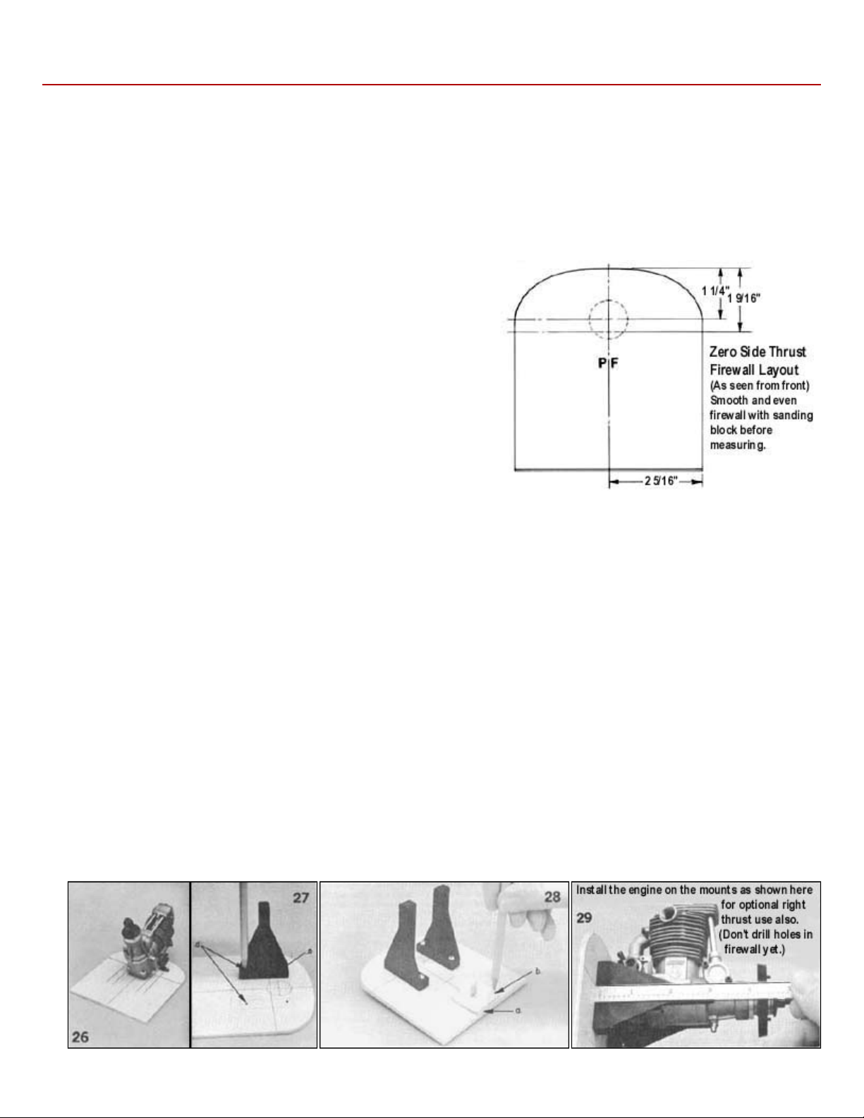
automatically incorporated without needing any extra effort or thought by the builder.) The pictures immediately following (26,
27, 28 and 29) will cover the engine installation as shown on the plan. After that we will show you an optional installation that
Photos 26, 27, 28 and 29 also show the hole necessary for installation
of a Sullivan RST tank, should you be using one. It will be placed as
shown, in either the zero side thrust or right thrust installation. Look
ahead in the instructions for more information on tank mounting.
25.
Mark the horizontal thrust locating line and vertical centerline on the
front of the firewall. (And the tank hole center, if used.
26.
Place the motor you will use on the firewall and draw lines as a guide
for positioning the glass-filled mounts. (Different engines have
different mounting dimentions.)
27.
28.
29.
a. Line up the marks on the side of the mounts at the horizontal thrust line.
a. Glue the hardwood wedge to the firewall as a nose gear bracket mount.
b. Position the nose gear bearing on the hardwood wedge, then mark and drill the holes using a 9/64" drill bit for the 4-
40 blind nuts.
c. Look ahead to picture 33 and you will see the 5/32"x9/16"x2-1/4" doubler strips on the back of the firewall as a base
for the 633 but if you are not using right thrust they will be centered. Be sure and epoxy the blind nuts to the back of the
doubler strips and the firewall so they will not come out later when it may be necessary to take off the mounts. Don't
get epoxy into the threads of the bolts. Pull the blind nut points tight into the wood with the bolts before the glue sets
nuts on the back of the firewall. This is to prevent any chance of the bolt ends puncturing the tank or rubbing on the
a. Bolt the spinner backplate to the motor. (This must be done to allow for the differences in spinners. For example, the
Goldberg spinner has a recessed backplate which requires the motor to be farther forward than a spinner without a
recess.)
b. Position the engine on the mounts so the spinner backplate will be 4-1/8" from the face of the firewall. It is handy to
tack the engine in position with some spots of 5 minute epoxy or thick cyanacrylate, brought up over the edge of the
edge of th engine to grip it good. Or a strip of double-stick masking tape is a little quicker, to keep the engine from
Page 9
.
job, don't try to punch and drill all 4 holes at once. Punch and drill
Adding right thrust helps the balance between high power and low
The landing gear wedge goes in the same place on the vertical
to the right (as seen from the front of the firewall) of the firewall
30. With a punch or sharpened piece of of 1/8" wire, center punch the
motor mounting holes. (Hint: If you are not used to doing this sort of
only one hole. Then put the motor back on the mounts, secured by
the first bolt. Punch and drill a 2nd hole, repeat the procedure, then
the third hole, etc. With this process you are much less likely to make
a drilling mistake that will ruin the mounts.)
OPTIONAL RIGHT THRUST
power trim. If you decide to use it, follow the pictures from here on,
keeping in mind the preceeding instructions as well.
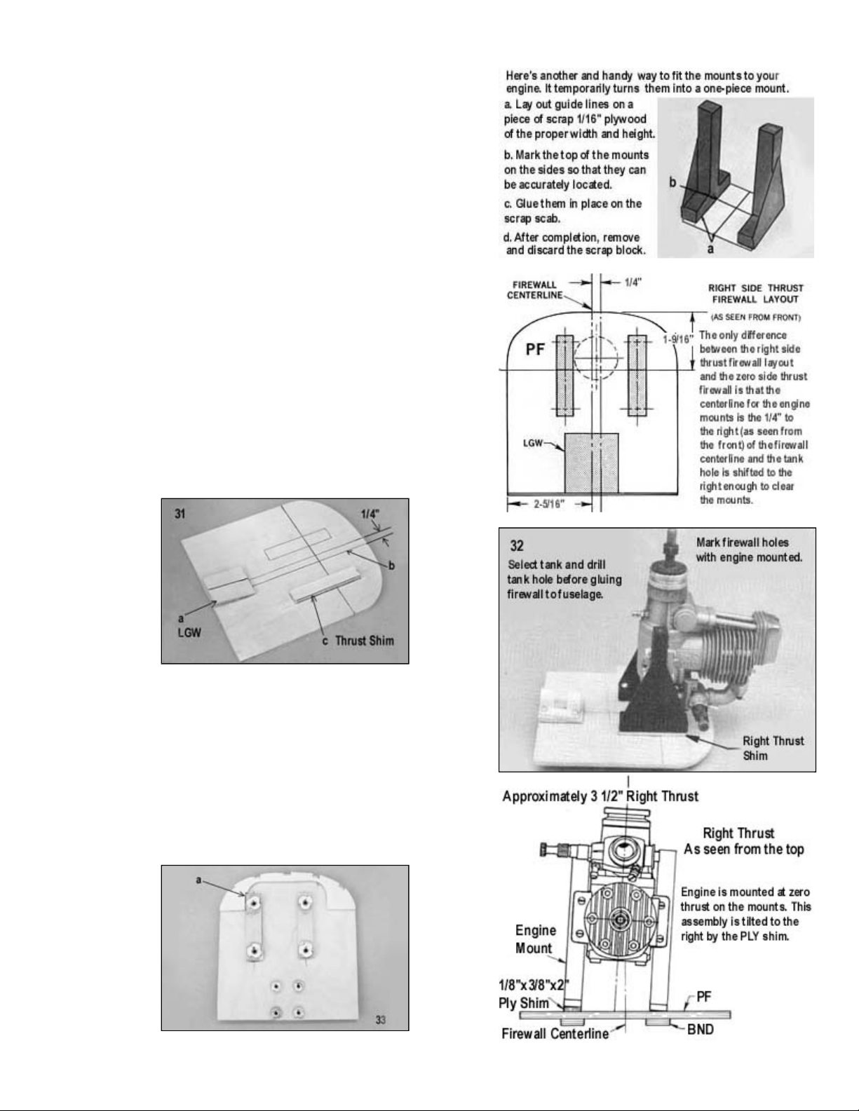
31.
a.
centerline as on the preceeding zero side thrust installation. (If
a Sullivan tank is used, the hole will also be in the same
place.)
b. A new vertical centerline for the engine mounts is drawn 1/4"
centerline.
c. A 1/8" plywood shim (included in the kit) is glued on the
position of the right (as seen from the front of the firewall)
glass-filled mount. Sand the face of it slightly at the angle
required for the mount to seat against it.
32. The engine is then mounted in this offset position. Because of the
angle provided by the shim on the one side, the prop is still
approximately in the center (not critical) but it now has several
degrees of right thrust offset.
33.
a. Because of the thrust offset it will be necessary to notch one
side of the FT former that is glued to the back of the firewall to
pass the 5/32"x9/16"x2-1/4" blind nut doublers strips.
Page 10
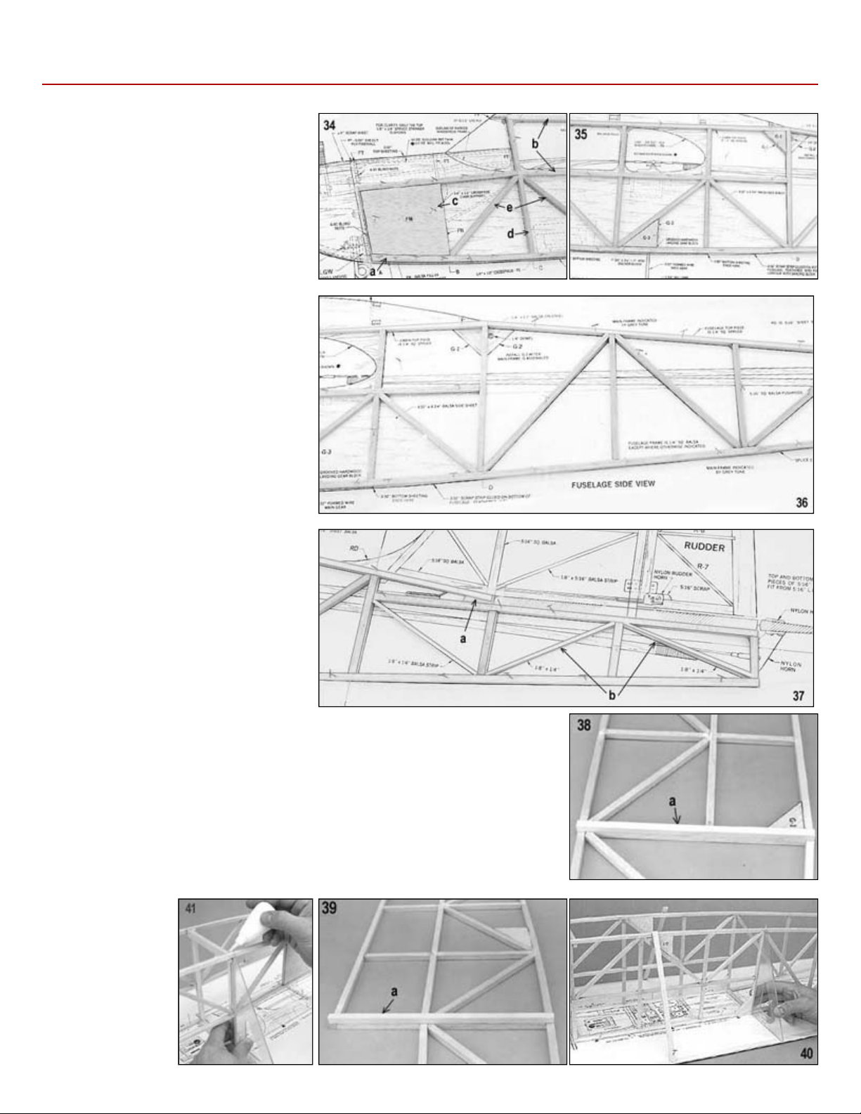
.
FUSELAGE CONSTRUCTION
wax paper at each point to keep from
exactly perpendicular. Here we show temporary braces tack glued to the fuselage
34.
35. Glue G-1 and G-3 into the side (Leave
36. Continue on down the fuselage with
37.
a. Soak the front end of the bottom
1/4" sq. fuselage stringer in
water so that it may be more
easily pinned into place on the
plan in the curved part at the
front.
b. Add the other lengthwise
stringers of spruce and balsa.
c. Glue in FN.
d. Install the vertical 1/4" square
balsa uprights.
e. Put in the 1/4" sq. diag. braces.
G-2 until later).
vertical and diagonal 1/4" squares.
a. Trim a piece of 1/4" sq. to fit
here.
b. In the rear of the fuselage the
diagonal braces are 1/8"x1/4"
balsa strip.
Build the second fuselage side directly
on top of the first side, using pieces of
gluing the sides together. Remove the
sides from the board and mark a left
and right side so as to insure the next
step is done correctly.
38.
39.
40. Using a straightedge to insure accurate alignment, join the two parts of the
41. Keeping check
a. Glue a strip of 1/4" sq. spruce to
the INSIDE of each fuselage
side at section "D", just behind
G-1 as shown.
a. Glue a strip of 1/4" sq. spruce to the INSIDE of each fuselage side at
section "C".
Fuselage Top View plan. Turn the fuselage sides upside down on the cabin top
and pin them to the plan in the cabin area. Make certain that they are supported
sides and to the board.
on the
alignment, add
FC
Page 11
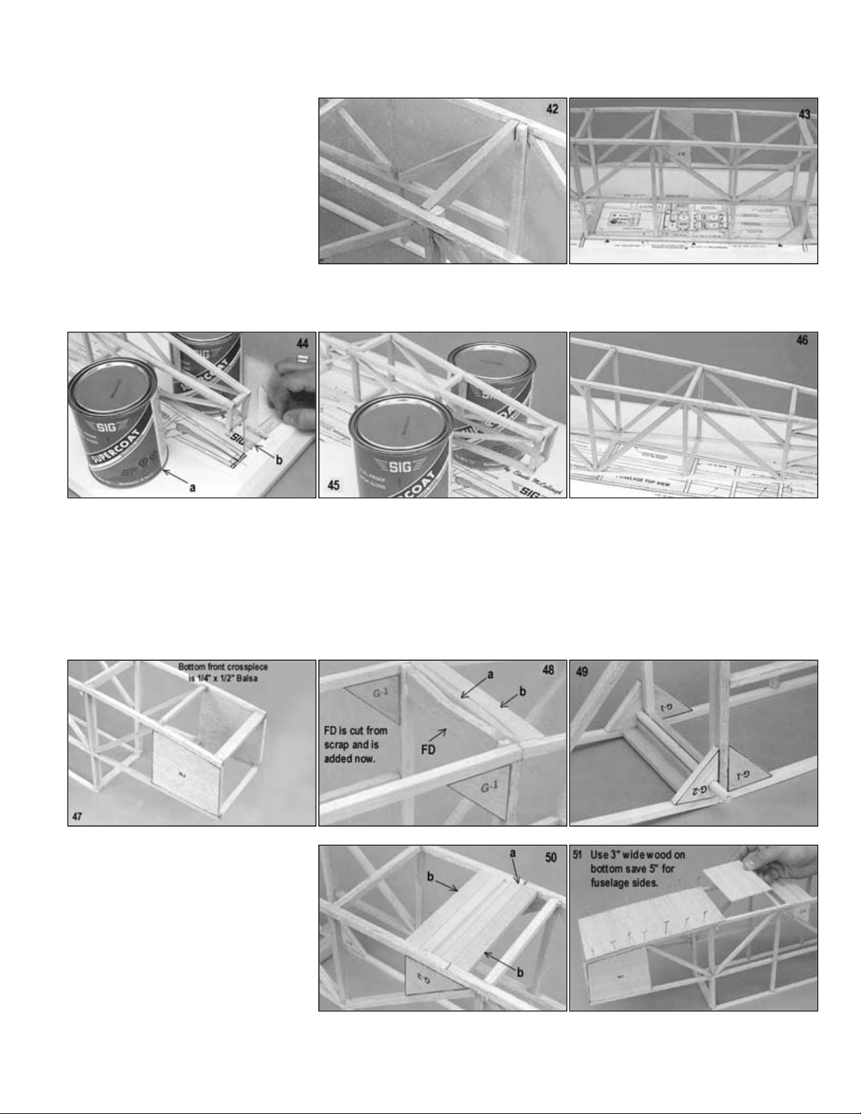
.
42.
A 1/4"x1/2" crosspiece on edge is used at section
-
D on the bottom.
Add the other rear cross pieces
in the area of the fin. They can be put in later, after the sides are removed from the board).
best to actually install them before the assembly has been unpinned and removed.
the first piece.
later so it will not be in the way of the fuselage covering.
landing gear block in place on the
43.
Glue in the bottom 1/4" sq. crosspieces.
44.
45.
46. Complete the 1/4" sq. fuselage cross pieces between the cabin and rear end. (Look ahead to see the extra top crosspieces
a. Use two flat sided weights to pull
in the fuselage sides at the tail
end.
b. Check with a 90deg triangle to
insure they are directly over the
plan.
47. This picture shows the front crosspieces in the nose section after the fuselage has been removed from the plan, but it is
48. Closeup of the fuselage top Section "D" - "a" is a 1/4"x1/2" piece on edge and "b" is a 1/4"x1/2" piece installed flat, behind
49. Shows the top section "D" as seen from the bottom. The 1/4" diameter rear dowl is fitted in now, but do not glue it in until
50.
51. Begin sheeting the fuselage bottom with
52.
a. Mark and glue the grooved
fuselage bottom.
b. 1/4"x1/2" crosspieces on each
side of the block installed flat.
3/32"x3" balsa with the grain running
across the fuselage. Save the 5" sheets
for the fuselage sides.
a. Complete the sheeting, leaving a gap for the landing gear groove.
b. Glue strips of scrap 3/32" sheet balsa to the bottom of the stringers as shown.
Page 12
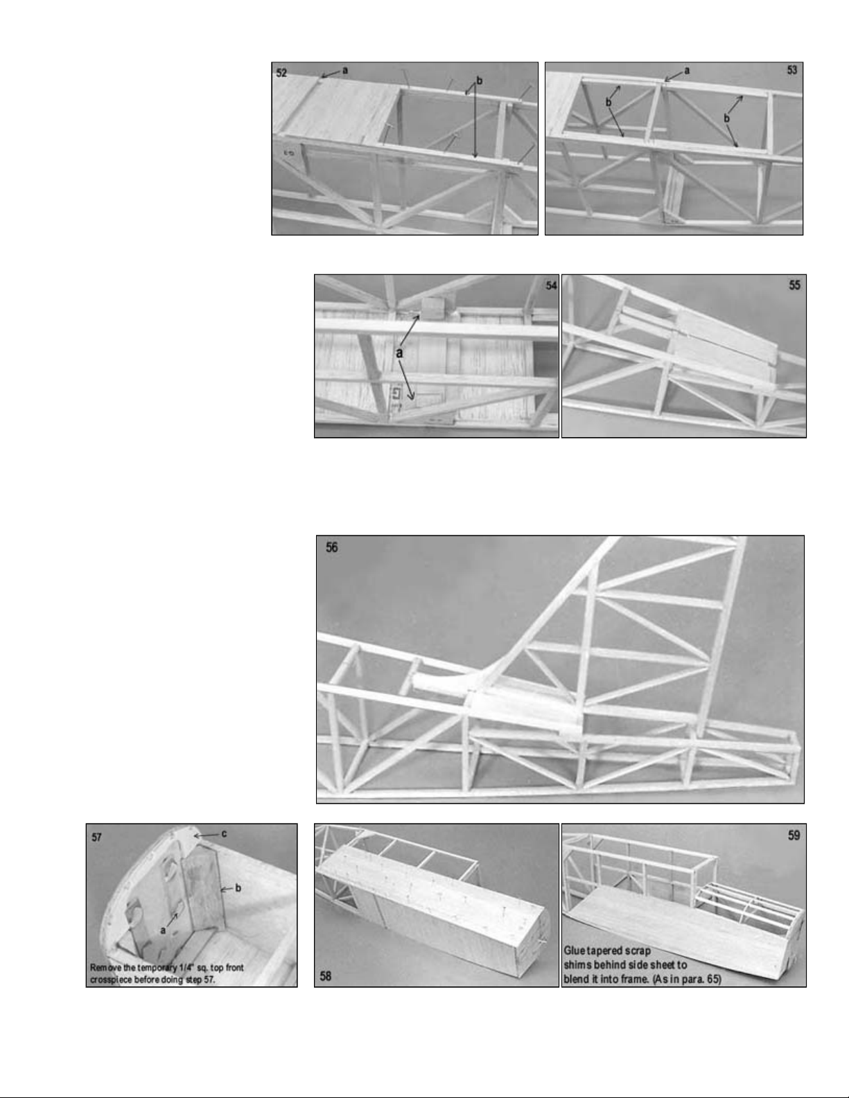
.
a.
Glue the hardwood anchor blocks on top of the grooved landing gear blocks and to the insides of the G
-3s
edge and the trailing edge to the fuselage frame.
tape to keep glue or fuel proofing
Epoxy 3/4" triangular stock in the
Glue one of the FT ply formers to
b.
Glue 1/8"x1/4" spruce stringers into the former holes.
53. a. Feather the scrap strips
into the lines of the
bottom, leaving them full
depth where they touch
the front sheeting,
tapering to nothing at the
back. (See fuselage side
view.)
b. Glue in the 1/4" sq.
stringer doublers.
54.
55.
a. Add the extra 1/4" sqs. on top.
b. Fill in the rear section with 1/8"
sheet.
c. Draw a centerline on the top of
the fuselage.
d. Cut Holes to take the fin stubs.
56. Shows the fin in place. Do not glue it on permanently until after the fuselage and fin are covered. At that time remove a
strip of covering under the fin so that there will be a wood-to-wood gluing surface. The same rule applies to the portions of
the stabilizer that are glued to the fuselage in the final assembly. Use a generous amount of epoxy to glue stab the leading
57.
58. Glue a 3/32"x4-3/4"x24" fuselage side
59. Trim the side sheet to fit.
a. Cover the firewall blind nuts with
out of them and epoxy the
firewall to the front of the
fuselage.
b.
corners.
c.
the back of the firewall.
sheet in place on the fuselage.
60.
a. Add the second and third FT formers.
Page 13
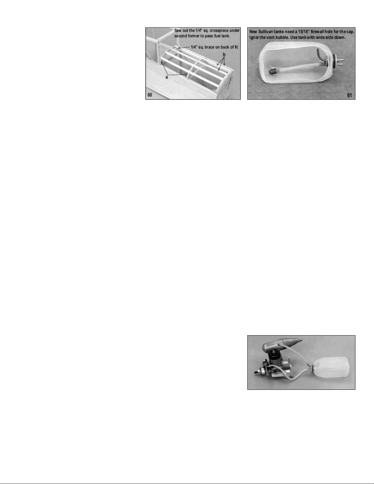
.
you'll find that the majority have
We show a Sullivan RST tank on the plans. Other types of tanks, such as the DuBro, will require slightly different mounting
following this tank section will show one of these tanks installed in the fuselage. The main difference in the tanks is that the
After installation, put fuel tubing on the vent tube and run it to the outside of the cowling on the bottom, so that fuel
your fuel supply can, and it is a good idea to have a filter between the tank and needle valve also.
tank in reverse from the pressure line, the tank will not fill properly and fuel may
be forced into the engine.
for each line.
1/4" sheet. If the grain does not allow bending it into position dry,
(We left the tank and lines in to show you more of them. Have them out when you are sheeting the top.)
61. We occasionaly receive suggestions
from builders that a removable hatch be
designed into a model for access to the
gas tank. Our opinion is this is not the
best method in most cases. The hatch
opening makes the nose weaker and
there is no good way to keep oil from
leaking in around the hatch. A method
of fastening has to be built into the
fuselage to hold a hatch in place.
Modern plastic tanks are virtually indestructable under normal use and bursting or cracking is almost unknown. If you use
Sig Heat Proof Silicone tubing (which will not harden or deteriorate in fuel) in the plastic tank, the tank will seldom have to
be removed. We have models in which the tank has been installed for three or four years without ever needing removal.
So it is quite practical to put the tank in semi-permanently. Check the models at a contest sealed noses, as does this kit.
and application but the principles discussed here are the same for all tanks.
The newer Sullivan type of tank requires a 15/16" diameter hole in the firewall through which the tank cap protudes, as we
show in the first part of the firewall section. So as to also cover the DuBro type of tank, the pictures of construction
cap of the DuBro tank is meant to remain inside the fuselage, with only the fuel lines going through the firewall. The
following comments apply to both types.
With most engines, the best installation will be with the tank as high in the fuselage as the cutouts in the FT formers will
allow. Put scrap wood crosspieces under and at the back of the tank. Seal the firewall hole with G.E. Silicone Bathhtub
Seal (available at hardware stores). Put an oil proof finish on the firewall and in the hole before sealing the tank cap or fuel
lines with silicone. Gel some of the silicone sealer in the hole and over the edge at the front. Don't install the tank
permanently until after the model is covered and painted. Should you need to remove the tank, break out the scrap wood
cross piece in the rear and push out the silicone rubber seal around the front. Reach into the fuselage and guide the tank
inside.
Some builders, after putting their receiver battery in a plastic sack, taping it shut, wrapping it in foam rubber package and
stuffing it into the nose under the tank, then stuff paper toweling or foam rubber in to fill the nose compartment and keep
everythig firmly in place.
overflow is not blown over the wing-fuselage joint, where it may leak into the fuselage. The best way to fill the tank is to
take off the fuel line to the needle valve and pump the fuel in there until it runs out the vent. Be sure and use a filter on
PRESSURE FEED
If the engine you are using is equipped with a muffler pressure tap, make use
of it for more even fuel feed and reliable operation. The hookup for pressure is
shown in the picture. To fill the tank, remove fuel line from the needle valve on
the engine and pump the fuel in. When the tank is full, it will overflow through
the muffler pressure line. Use transparent or translucent fuel line so you can
see the fuel starting to overflow when the tank is full. Should some fuel happen
to get in the muffler, drain it out before starting the engine. Do not try to fill the
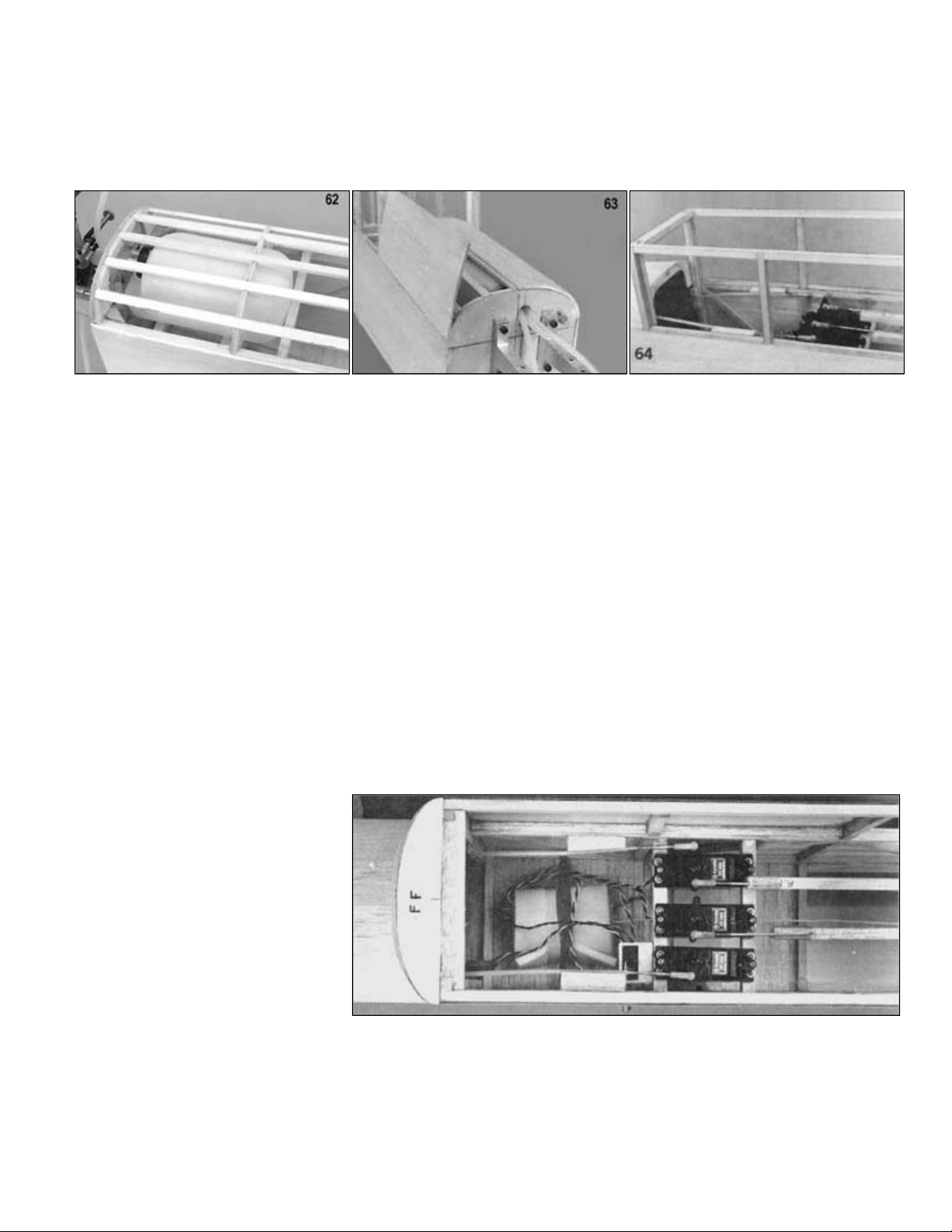
62. Shows a DuBro 8oz. tank installed in the fuselage. Also see the next picture. Two lines are enough unless you have a fuel
fitting on the carburetor that is not accessable. In this case, use a 3rd line as a fill tube. You can also use individual holes
63. Cover the top of the fuselage nose with pieces of 3/32"x3-
and it likely will not in many cases, dampen the top of the sheet with water and allow it to soak in before curving it into
place on the formers. It helps to have one edge glued on first, as shown here, rather than trying to put it on in one step.
Page 14
.
wheel will give the pushrod movement direction desired. Sometimes this requires that a pushrod brought down the side of
were the opposite direction of pushrod movement without changing servo sides is desired. For example, it is desirable to
converters that can be plugged into a servo cord to reverse the direction of movement of a standard servo. But if you do not
have a reverse servo it is quite possible to get along without it.
bearing. This setup would be the case with most glow
-
plug engines, as with the Fox shown on the plan.
circumstance. On this engine the throttle
the rudder horn to be located on the right
As you can see, it is best to know in advance the radio and motor brand you will be using before you install permanent
connectors shown without preliminary planning.
64. On the plans we show the servos mounted high in the fuselage for easy access. Some think this spoils the appearance,
since they stick up and show through the windows. So in this picture we have a 3-servos-abreast installation mounted a bit
lower, below the cabin window line. Because Futaba doesn't make a 3-servo tray of this type, we used three single FST28V trays. You can also see the flexible cable pushrods running from the throttle and nose wheel and glued to scrap
standoffs. Silicone seal makes a good adhesive for fastening the outer tubing to the fuselage because it is slightly flexibile
and doesn't make a hard spot in the tubing.
Life is not simple in the model game when it comes to pushrod installation. Most servos are standardized as to which
direction they move in response to a particular transmitter stick movement but there are exceptions. Regardless of the
direction of movement of the servo, you can adapt to it by moving the pushrod to whichever side of the servo output arm or
the fuselage has to crossover to the inside of the servo output arm to get the desired direction of pushrod movement.
Some radio manufacturers make available reverse direction servos and often include one or more in an outfit for situations
have the hookup for the pushrods to the nose on the outside of the servo so that the pushrod tubing need not be flexed as
far as crossing over to the inside would require. At the same time the pushrods to the tail would be on the inside where
there is plenty of room to maneuver it around. The current trend is for equipment to have a servo reversing switch built into
the transmitter. If the servo doesn't run the direction you prefer, just flip the switch. Several companies make reversing
WHICH SIDE FOR THE RUDDER PUSHROD?
The choice of which side of the fuselage the rudder pushrod will exit from is determined by the position of the throttle
control arm on the engine to be used. If it is on the right (most common), use the servo nearest the right side of the
fuselage for motor control. Use the servo nearest the left side of the fuselage for the rudder, with the rudder pushrod
coming out to the left side of the rudder and the nose wheel steering arm hooked up on the left side of the nose gear
The opposite is true of the O.S. .40
Four-stroke we are using in the picture
sequence so as to cover this
arm is located on the left side, so the
servo on the left side would be used for
engine speed and the one on the right
for rudder and nose wheel. This calls for
side of the tail instead of on the left as
the plan shows.
cable pushrods. Decide on which type of fittings you will use in the case of the cable pushrods and have them on hand
during construction because the type chosen will affect the location of the pushrod exit holes through the firewall, etc. The
balsa pushrods to the rudder and elevator are not limited as to location and can be adapted to any of the types of
Page 15
.
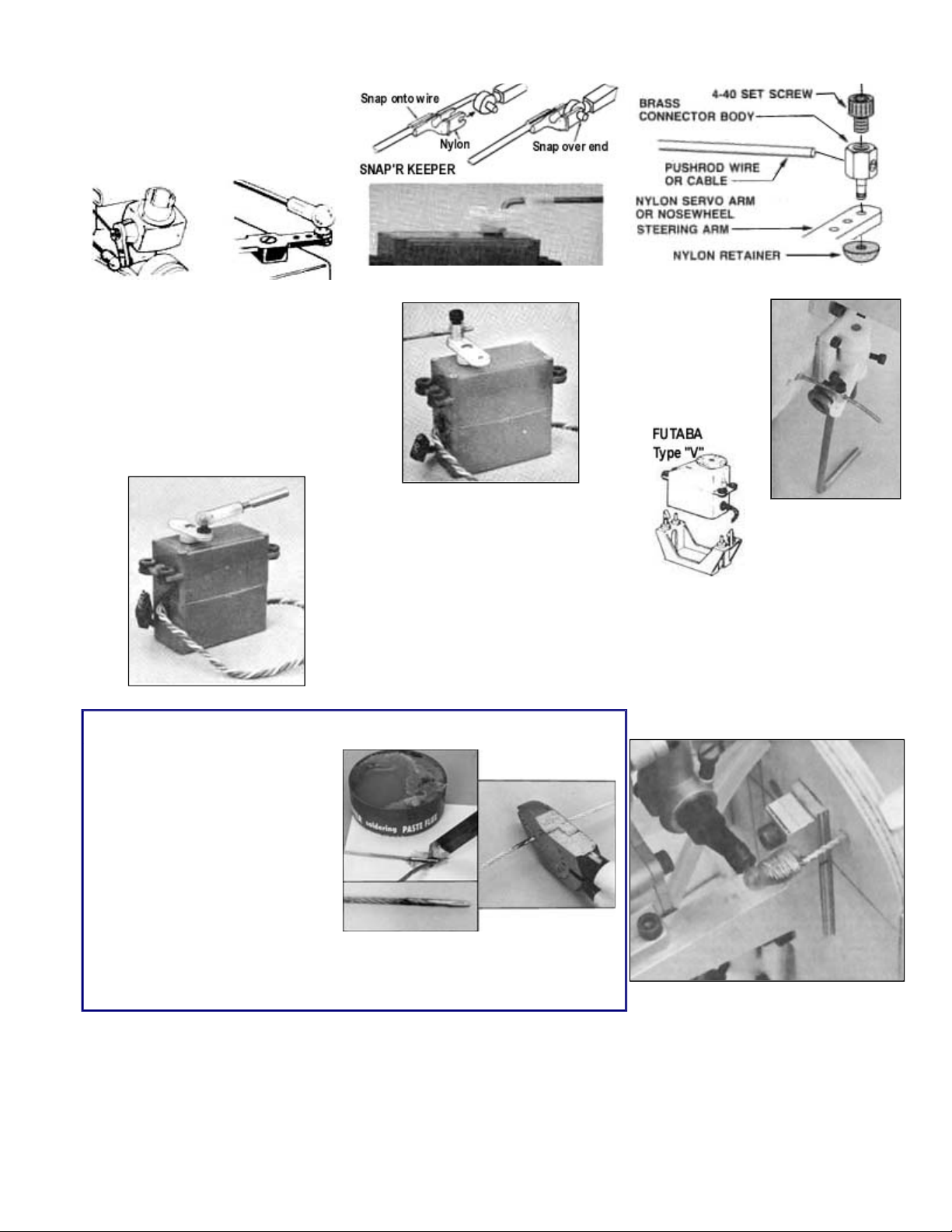
SERVO HOOKER
-
UPPERS
pushrod can approach from a variety of
interfering with the servo center post. It
The Sig Pushrod Connector included in
736) for use on the throttle
Angle the nose gear steering arm
forward in neutral to allow more range of
FOUR CYCLE THROTTLES
end of the throttle control cable with epoxy glue and fine copper wire. The photo shows this installation.
Having the proper connector makes
servo installation much easier. We
show here a variety of ways to attach
pushrods to servos.
DuBro Ball Links, which come in
several different types - threaded, bolton, rivet etc. - gets the pushrod action
up above the control arm so the
angles without any chance of
is good for cable pushrods. A line
adjustment can be made by screwing
the end in and out.
PREPARING CABLE PUSHRODS
this kit can be used for attaching the
nosewheel pushrod cable to the
steering arm as shown. Additional
pushrod connectors can be purchased
(Sig No. SHand nosewheel servo arms. Adjust by
loosening the set screw and sliding the
cable.
A typical Futuba
plastic servo
mount. Similar
mounts in a variety
of styles are
available from
most radio makers.
movement.
To keep ends of cable from
unraveling during handling, tin the
end with solder. Use a non-corrosive
paste flux (shown here is Kester,
available at hardware stores) and
rosin core solder. Have a hot iron
and flow the solder completely
through the cable.
Grind or file the end smooth. Bring it
to a point so that it will easily insert
into the pushrod fittings.
After the proper length is arrived at, sweat solder the area to be cut so that it
will not fray and unravel while being cut. It can be cut with a good pair of sidecutting pliers, filed in two, ground through on the edge of a grinding tool, or cut
with a silicon cutting wheel on a motor tool.
It is common for 4-cycle engines to have their throttle control arm on the back of the engines, unlike 2-cycle types which
have front carburetors and plenty of room in front of the firewall for adjustable linkages and couplers. In the installation of
the O.S. 4-stroke, we got around this problem by use of a DuBro 180 Bolt-On Link. The ball was bolted to the carburetor
arm. Since there was no room for the threaded coupler, it was discarded and the nylon ball link socket was bound to the
Page 16
.
covering a neater job.
main necessity here is to avoid warping this thin assembly. Therefore do not use water base glues such as Sig Bond or Tite
to the frame, sit the clear plastic on the pins as shown in this picture and hinge it down onto the glue.
tape will work if you do not leave it on too long.
up. Taping the rest in place helps.
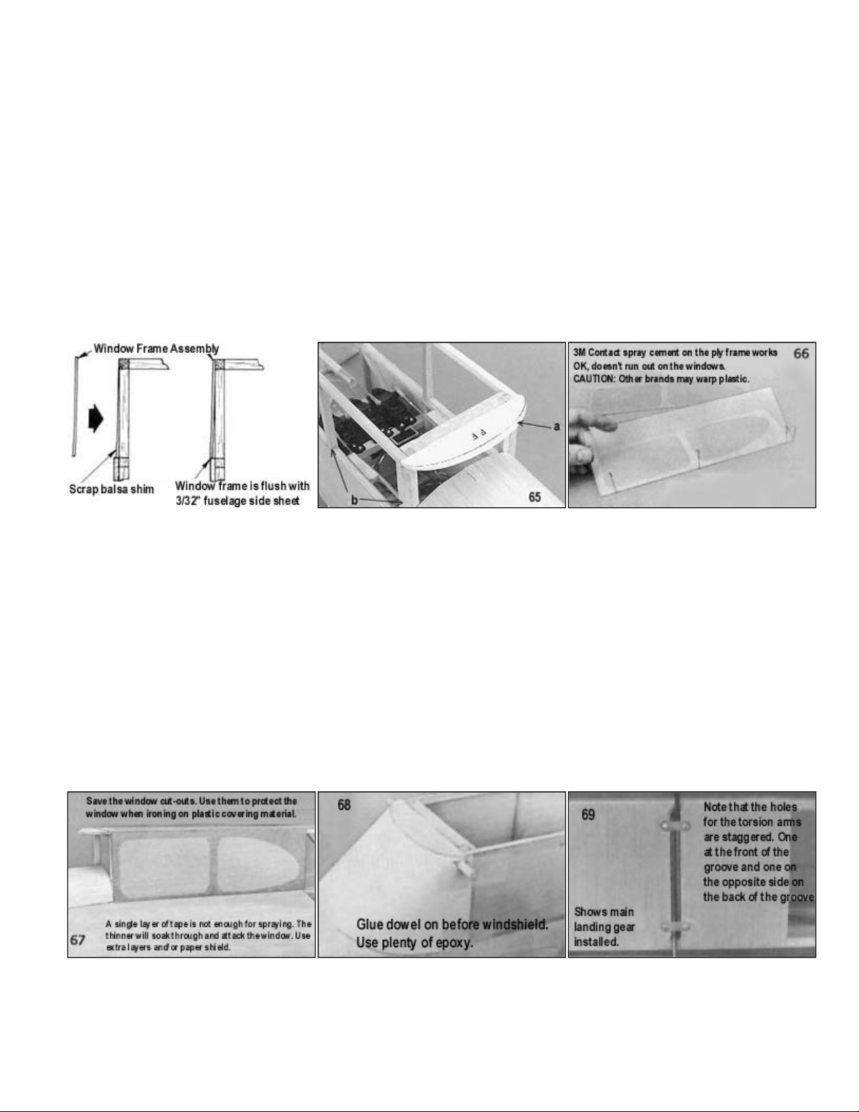
69. Drill 5/32" holes into the anchor blocks for the torsion arms. Recess nylon straps into the 3/32" bottom sheeting.
cowl main shaping and sanding is completed. If you make use of a longer cowl for a specialized engine you will have to plot
easier to glue the 1/8" bottom sheeting.
65. a. Pre-bevel the front edge of FF, using the pattern on the plan and glue it onto the front of the cabin.
b. Glue tapered scrap shims on each cabin window upright. The idea is for the cabin window frame to be flush with the
fuselage sides at the bottom and glue directly to the top edge of the top spruce cabin stringer at the top. (See crosssection drawing here.) Shims are also a nice idea on the sides just behind the cabin window frame. It makes
66. The clear cabin windows are glued to the inside of the die cut ply window frame. Make sure you do it left and right. The
Bond. Do not use cements like Sig-Ment or Ambroid. The ideal adhesive appears to be slow-setting cyanoacrylate but
precautions should be taken for this to come out right. First, make sure the ply frame will stay in place on the table by
fastening it down with double-stick tape or a tack-glued corner or two. Then stick several pins along the bottom as guides.
Have one at the corner to position the window material lengthwise as well (The pin seen on the far right). The critical step is
next, getting the right amount of glue. About a 3/32" diameter bead, located 3/32" to 1/8" from the window frame edge is
approximately correct. The idea is for the bead to spread almost to the edge, but not over it, when the clear plastic is
pressed down. Too big a bead and it will squeeze out onto the window. Since glues are of different viscocity, I'd suggest a
trial run on a bead size with scrap plastic from the windshield. Also, of course, put glue beads on the frame farther away
from the window outline, such as in the back portion that is a long way from a window. So having practiced, apply the glue
67. So that the clear window will not be damaged during handling and covering, protect them with masking tape. Use a sharp,
new modeling knife to trim the tape against the edge of the ply frames. We covered right over the masked-off windows with
silk, then doped the silk, finally trimming it off flush with the ply frame and removing the tape last. It is also a good idea to
tape the inside of the windows. This doesn't need to follow the frame lines, just cover the whole clear window. Caution:
Don't leave the tape on a long time, it dries out and sticks down tightly. Low tack drafting tape is best for the job but regular
68. We have previously established the final windshield pattern shape. Now use the pattern to locate the position of the dowel
holes in the windshield. Use plenty of epoxy glue to glue the dowel to the fuselage and to former FF. Make a fillet of epoxy
over the dowel on the face of the verical 1/4" sq. balsa and 1/4" sq. spruce. Do the same for the areas where the fuselage
crosspieces attach to the fuselage sides. Cover and/or paint the model before gluing on the windshield. Use Wilhold RC-56
or cyanoacrylate glue to attach the windshield. It helps to glue down one side of the windshield to the fuselage first so you
can pull against it to stretch the rest of it into position for gluing. Make certain, however, that the first side is properly lined
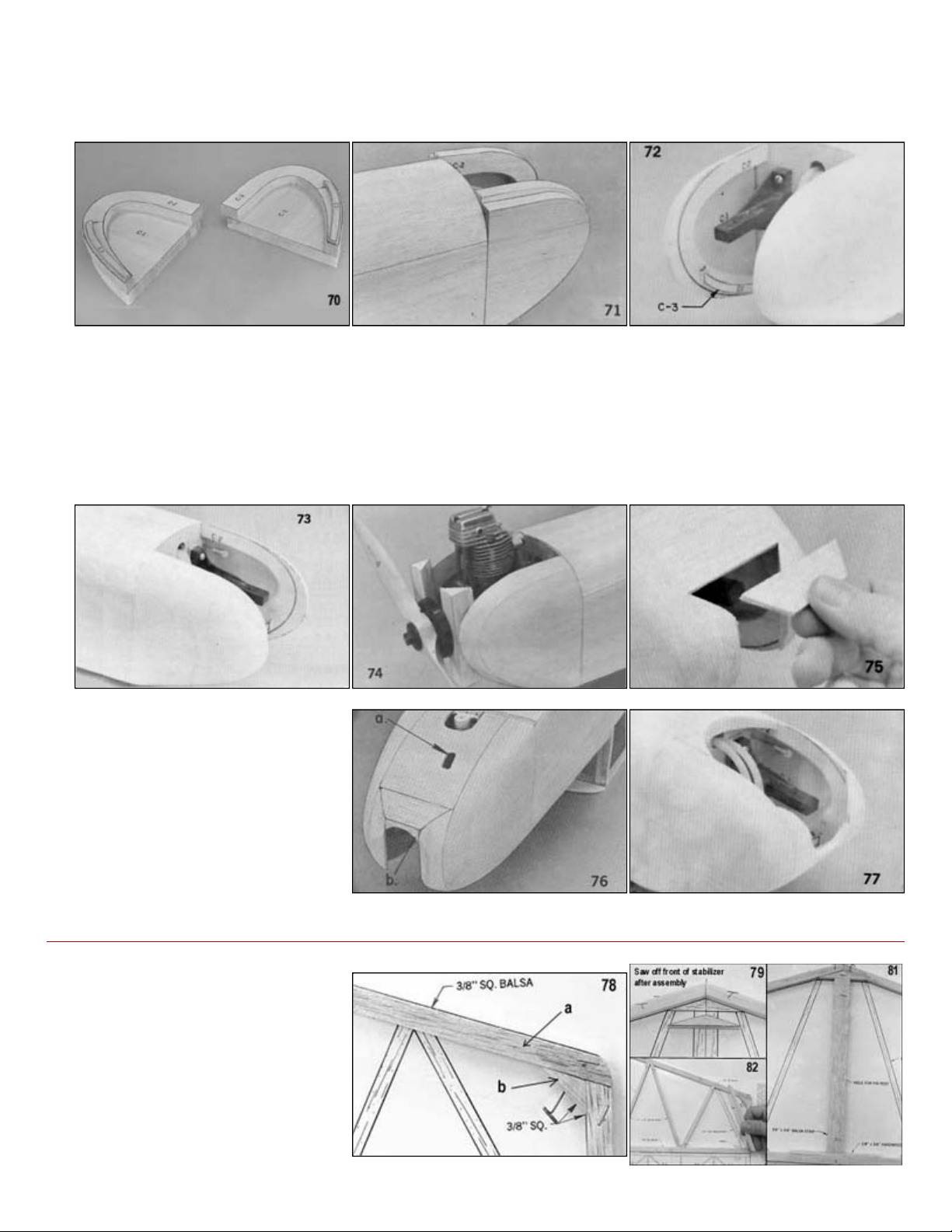
70. Cut out the cowl parts C-1 and C-2 and glue together as shown. Note that the bottoms are lined up flush and the backs are
even. We have laid the C-3 parts in place here to show their general location but do not glue them in until later, after the
a new C-3 to match the modified shape. The cowl used on the plan will fit most engines. C-3 simply makes a notch so it is
Page 17
.
71.
Glue the cowl halves to the fuselage, flush with the bottom and sides.
72. Carve the cowl sides to a pleasing shape. Add C
-
3 exactly 1/8" deep from the sanded bottom cowl shape.
2 on the
blocks desired are added.
as a guide for correct placement. Don't carve to final shape until top and bottom wood is in place.
75. Cover the bottom with 1/8" sheet balsa.
We added some more scrap wood to the
73. Cut away the inside of the cowl to clear space for pushrods or engine parts. It is a good idea to carve a taper into C-
inside to make it easier to paint or fuel proof the cowl interior, but do not do this until later, after the front and any top fill-in
74. Put the spinner backplate on the engine and glue on pieces of 3/4" triangular stock as shown, using the spinner backplate
76.
77.
a. Cut a hole for access to the nose
wheel steering arm adjustment
screw.
b. Add scrap wood as desired to
complete the cowl shape
top to improve the appearance. This
addition is determined by the engine
used and/or your preference.
TAIL SURFACES
78.
a. Pin down the pieces of 3/8"
square for the outside frame of
the stabilizer.
b. Make a corner gusset from scrap
wood.
79. Cut center brace to fit.
80. Glue in place
Page 18
.
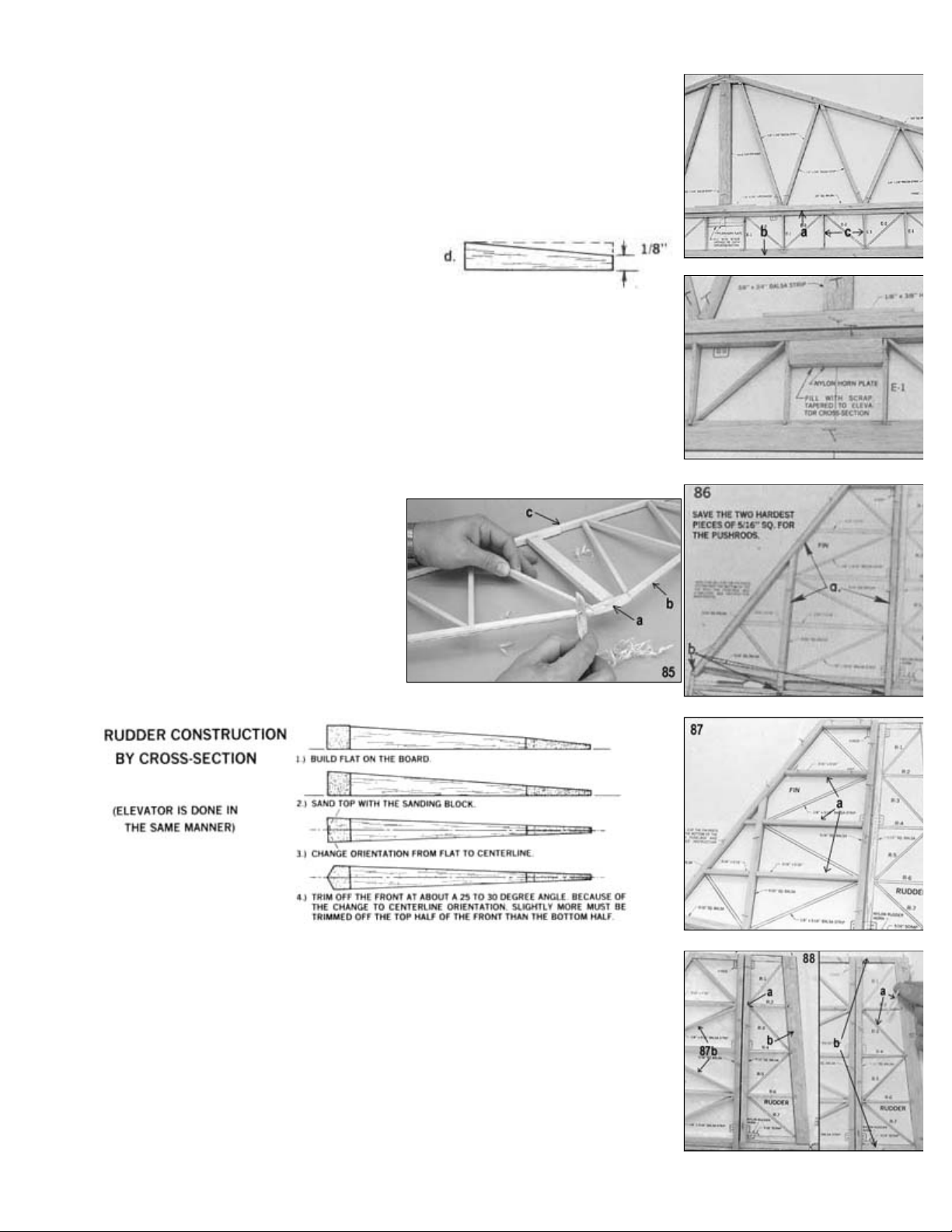
81. a. A 1/8"x3/8" hardwood brace is glued across the back.
b. Next add the 3/8"x3/4" strip center rib.
82. Cut and fit 1/4"x3/8" strips of balsa.
83.
a. Pin down the 1/4"x3/8" elevator leading edge.
b. Pin down the notched trailing edge,
c. Glue E-1 elevator ribs between them.
d. Pre-taper 3/8" sq. ends.
84. a. Add the diagonal elevator ribs.
b. Fill in the center with scrap.
85.
a. Saw the front off and leave it square and unshaped.
b. Shape the leading edge to a rounded contour.
c. Do not shape the stabilizer trailing edge. Leave it square.
86.
a. Pin and glue pieces of 5/16" sq. balsa to
make the main frame of the fin.
b. Note the stubs, left on below the bottom fin
line.
87.
a. Add 3/16"x5/16" ribs.
b. Glue in 1/8"x5/16" diagonal braces.
88.
a. Pin down the 5/16" sq. rudder leading edge.
b. Pre-notch the shaped rudder trailing edge. (It is not practical to suppy it notched
accurately at an angle as required.) Pin down to the plan.
c. Glue R-2, R-4 and R-6 ribs between them.
89.
a. Add the diagonal ribs R-1, R-3 and R-5.
b. The top and bottom of the rudder are pre-tapered pieces of 5/16" square.
Page 19
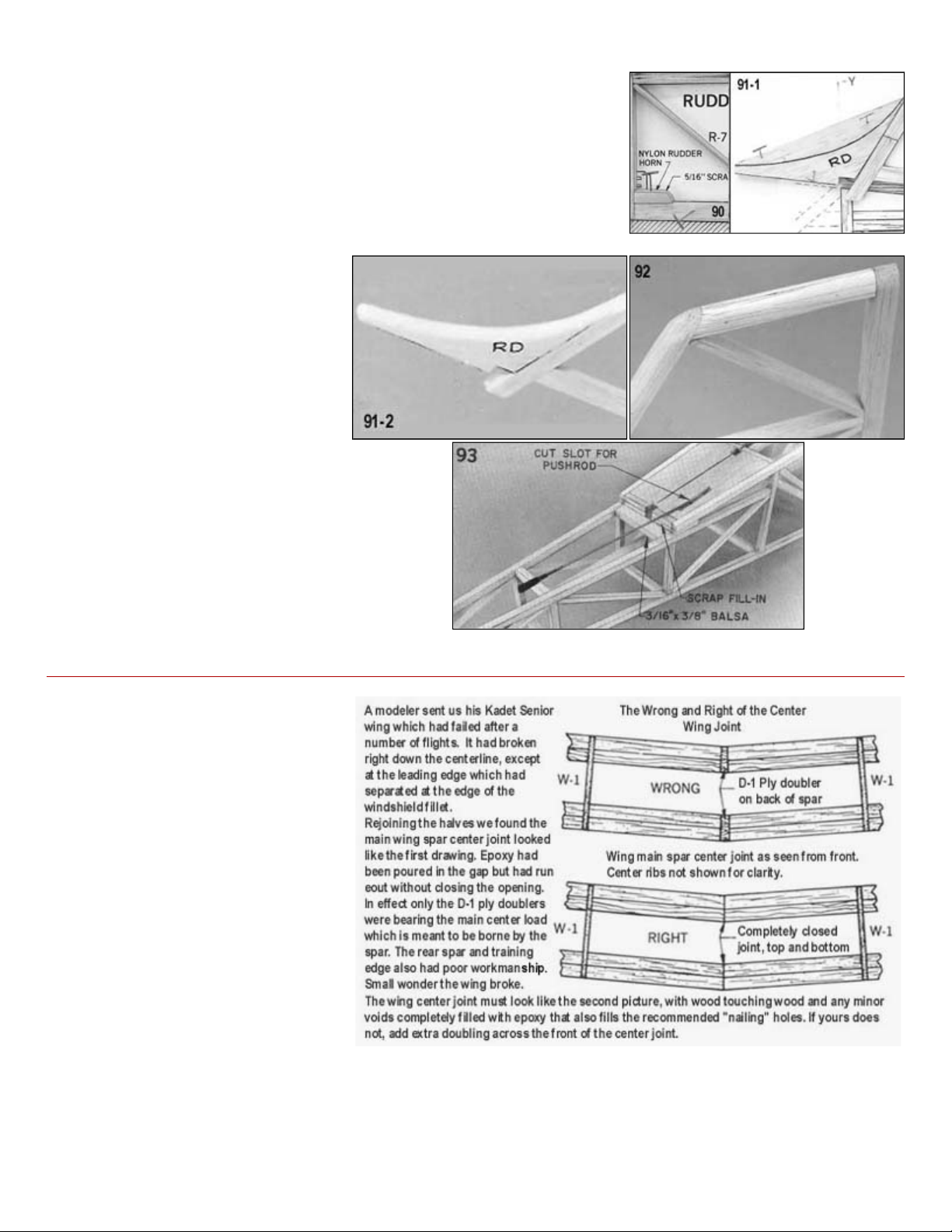
.
control surfaces all separately before
A CAUTION ABOUT THE KADET SENIOR WING
A recent experience leads us to add
job if it tacked on with a few drops of
Check the structure carefully after a cartwheeled landing or a flipover. The dihedral joint or other seam could be cracked or
damaged internally, setting up a condition for later failure.
90. a. Fill in some scrap as a control horn mounting place.
91. Glue RD in place on the fin leading edge and shape.
92. Carve the fin leading edge and tip to a rounded shape. (The elevator tip is
similarly shaped.)
93.
a. Although it isn't shown on the
plans, you should add a scrap
piece of 3/16"x3/8" balsa as
shown in the photo to provide
additional gluing area for the
stabilizer.
b. Cut a slot in the 1/8" balsa sheet
for the rudder pushrod (see
"Which Side For Rudder
Pushrod" detailed earlier.)
We recommend that you cover the
wing, fuselage, tail surfaces, and
hinging and final assembly. This
way, the parts are much easier to
handle.
further caution to the one here.
It is simply: USE ENOUGH GLUE! Even
in properly fitted structures, a failure can
occur because of an inadequate amount
of glue holding the parts together. A ply
dihedral brace, for example, can't do its
glue. Strain will cause these spots to
pop, transferring stress to other joints, in
turn resulting in catastrophic wing
failure. All surfaces joined together by
glue should be fully coated, a wet joint,
before assembling. Clamps should be
used to hold dihedral braces firmly to
the spars until dry.
If cyanoacrylate glues are used, the thin
variety works well in small joints that are
tightly fitted. Large are joints, such as
those under doubler braces, are best glued with slow cyano or epoxy applied before joining, because the thin variety may
not penetrate completely between the two surfaces when applied to the outside seams. For best safety in structures that
are assembled with thin cyano, we recommend going over the joints and "filleting" them with a second application of
medium or thick cyano glue.
Page 20
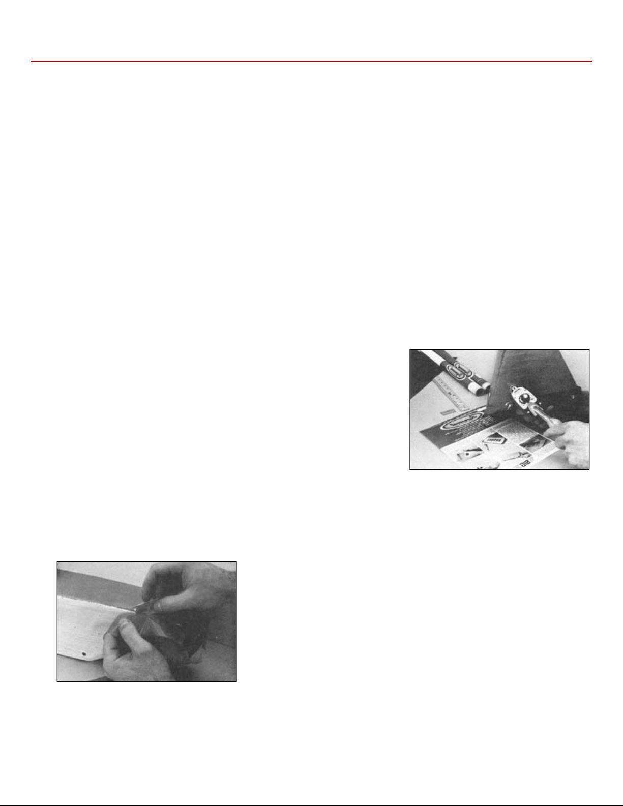
.
COVERING AND FINISHING
carefully with fine sandpaper (360
-
400 grit) before beginning to cover.
COVERING WITH SIG SUPERCOAT IRON
-
PLASTIC COVERING
like to paint or have workshops located where paint fumes can't be tolerated. Others like the speed and ease of application
on covering rather than a painted
covering. On the plus side, plastic coverings are fairly easy to apply and result in a glossy, smooth finish. Plastic coverings
use one color for the wing and another for the fuselage, or go with all one color. Two pages of photo illustrated instructions
are supplied with each roll of Supercoat, so only a quick outline will be presented here.
modelers prefer to cover their tail surfaces before gluing them to the fuselage so
in place. Thin strips can be cut from SuperTrim sheets or you can use one of the many brands of striping tape (such as Sig
wing so that while you are flying it is easy to distinguish the top of the airplane from the bottom.
There is a variety of covering and finishing methods available that are well suited to the Kadet Senior. The final choice
should be made after reading through each part of this section so that you can make an informed decision. Plastic iron-on
coverings are popular because they are fast and easy to apply. Sig Koverall will give the model the strongest and most
durable finish; while materials like silk, silkspan, and silray will appeal to the more traditional modeler
IMPORTANT! If you plan on using a finishing method that requires painting (Koverall, silk etc.) don't skip covering the
fuselage and tail just because they are solid wood. Painting them without covering first is not enough. They will be much
more resistant to splitting and breaking on hard impacts if covered, than painted.
Regardless of which covering you decide to use, it will not conceal a rough framework. Take the time to sand the model
Many modelers prefer to use an iron-on plastic covering on their models for several reasons. Some modelers simply don't
afforded by plastic coverings. You can generally finish a model much faster using an ironfinish. However, plastic coverings are less durable and do not add nearly as much strength to the structure as fabric
tend to be susceptible to punctures and tears, but they are easily repaired.
If you decide to cover your model with this type of material, we recommend Sig Supercoat Iron-On Plastic Covering for it's
low cost, light weight, and ease of application. To cover the Kadet, you will need at least four rolls of Supercoat. You can
SURFACE PREPARATION
Like any other type of finish, Supercoat will not hide poor workmanship. The
entire framework should be given a final sanding with 360 or 400 grit sandpaper
before application of the material. Wipe the surface with tack rag or cloth
dampened with alcohol to remove all excess dust.
COVERING THE WING
Cut a piece of material slightly oversize, remove the protective plastic backing sheet, and lay the adhesive side of the
covering material against the structure. Tack the material in place around the edges using and iron to activate the
adhesive. Seal the entire edge, then trim off the excess. Repeat this process for the top of the wing, being sure to overlap
the material about 3/16" to 1/4". Always plan your covering sequence so that seams are on the bottom surface or at
corners so they aren't so easy to see. Once both top and bottom have been covered, shrink the material with an iron or
heat gun, heating evenly from one side to the other.
COVERING THE FUSELAGE
Cover the bottom, the two sides, then the top using separate pieces of material
for each. When covering solid surfaces like the fuselage nose, better results
may be obtained by starting at the center and working towards the outer edges.
This allows the air to escape from under the covering as it is applied. Some
that they are easier to handle. Be sure to cut away any covering where the
surface attaches to the fuselage so that you have a strong wood to wood joint.
FINISHING TOUCHES
Once your model has been covered, you can add trim decorations using Sig SuperTrim Self Adhesive Trim Sheets.
SuperTrim is made of the same material as Supercoat, but it has a sticky backing. Simply cut out your design and stick it
SuperStripe) which come in various colors and widths. Be certain to add some kind of stripe or decoration to the top of the
Page 21

.
COVERING WITH SIG KOVERALL
it will actually add strength and rigidity
003, 48"x5yds.) is enough
adhesive.
covering material makes contact. Lightly sand after each coat to remove any raised grain or fuzz.
or places that are not stuck down properly and apply more dope. Let dry.
It was applied.
After both sides of the surface are covered (such as the top and bottom of the wing), shrink the Koverall evenly with an
dope until it brushes on easily and flows out smooth (about 25% to 30% thinner). The first coat should be applied sparingly
Painting the entire model white is recommended for a good color base, particularly when white is part of the color scheme.
Complete the job with several sprayed coats of clear over the color scheme. This seals the colors and adds gloss. For best
results, it is not a good idea to try to mix different brands of paint. Use SIG products from the start.
COVERING WITH SILK, SILKSPAN, OR SILRAY
Although we refer to silk in the directions, all of these coverings are applied wet in the same manner as follows. Brush an
and sand again.
Sig Koverall is relatively inexpensive, synthetic polyester-base, heat shrinkable fabric much like the covering used on fullscale aircraft. It is the strongest and most durable finish you can put on your Kadet to the model's framework. If you are careful in cutting the material, one large sized package (KVto cover all the parts of your Kadet. It can be applied to the model using dope or ironed on using Stix-It, a heat activated
SURFACE PREPARATION
Whichever application method is used, you should first brush two coats of clear dope onto the framework wherever the
APPLYING KOVERALL WITH DOPE
Start with the bottom of the wing by cutting out a piece of material about 1/2" larger all around the panel, with the grain
running spanwise. (The grain of Koverall runs parallel to the finished bias edge.) Lay the Koverall on the wing, pulling out
any major wrinkles. Unlike silk, which uses water to shrink it tight, Koverall uses heat. In fact Koverall shrinks so well that
there is no need to worry about such things as packaging folds or creases because they will come out easily with the iron.
Brush clear dope around the edges. This will soak through the fabric and adhere it to the dope already dried into the
framework. Allow dope to dry before trimming off the excess material with a sharp razor blade. Check for any rough edges
APPLYING KOVERALL WITH STIX-IT
Directions for applying Koverall with Stix-It are on the can. The basic procedure is to apply Stix-It around the edges of the
framework where you want the covering to attach. When dry, the fabric can be ironed-on around the edges where the Stix-
SHRINKING AND SEALING KOVERALL
iron or hot air gun. (Be sure to read the Koverall package instructions.) The fabric can now be sealed with three or four
coats of clear dope. Since Koverall has such a tight weave, fewer coats of dope are necessary to fill it than silk. Thin the
to avoid puddles underneath the fabric. The second coat will seal most of the pores of the Koverall and from then on,
running through will not be a problem. Sand the model VERY LIGHTLY with FINE sandpaper after the second coat is dry.
The next two coats will completely seal and begin to fill the weave of the fabric. When dry, sand again. Your Kadet should
now be ready for its colored paint scheme.
PAINTING
Color Dope should be thinned with Supercoat Thinner for brushing. This helps prevent brush marks and gives smoother
coats. Flow on wet coats and avoid rebrushing back over an area already painted. If brush marks show, you need more
thinner. For spraying, thin dope about 50-50. Add more thinner if the dope does not go on evenly.
If high humidity causes the dope to "blush" or turn white, the best way to handle this problem is to wait until the humidity
situation improves and apply another coat of dope. This will eliminate the blush. If it is necessary to dope during high
humidity, Sig Retarder may be used in place of part of the Supercoat Thinner (amount depends on the humidity) to reduce
the tendency to blush.
Color coats can be sanded with 360 Tri-M-Lte or 400 or finer wet paper. When using masking tape for trimming, seal the
edge with a coat of clear dope to prevent the color dope from bleeding under the edge. Don't leave the masking tape on
any longer than necessary. The longer it is on, the harder it sticks.
unthinned or very lightly thinned coat of clear Sig Supercoat or Sig Lite-Coat Dope over all parts of the framework that will
contact the covering. When dry, resand with fine sandpaper to remove any fuzz or raised grain. Brush on a second coat
Page 22
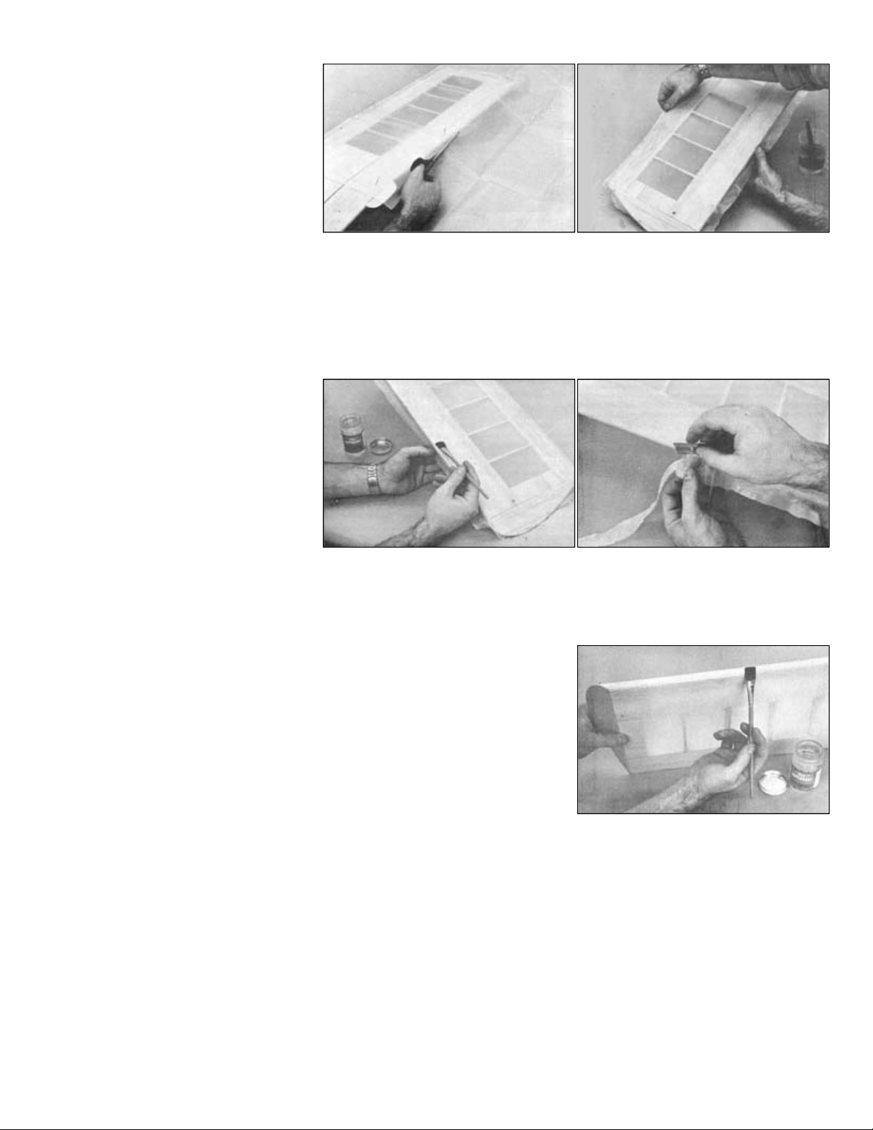
.
to start covering. Cut a piece of material
shown in the photo. Pin the dry covering in place and "paint" the water on with a brush.
joint of the wing
stretched silk with clear dope. The dope
will soak through the material and
edged blade does
and getting stickier.
Allow the water to dry out of the wood before applying the first full coat of clear dope. On the open framework area on the
wing, brush the dope on sparingly. If too much is applied, the dope will be rubbed through the material and will run down
second coat will seal most of the pores of the material and from this point, running through will not be a problem.
A third coat of clear should provide a good base for color. Sand lightly when dry with 360 grit 3M Tri
Apply the colored dope to the silk exactly as described in the "COVERING WITH SIG KOVERALL" section, starting with
the white base coats.
The bottom of the wing is a good place
about 1/2" larger all around than half
the wing, with the grain running
lengthwise. (The grain of woven
materials runs parallel to the finished
bias edge.) Some builders next dip the
piece in water and apply it to the wing.
We find that the silk sticks together and takes a lot of pulling and smoothing to get it in place so we do it a bit differently, as
Go around the edges, pulling out wrinkles and stretching the material smooth. You need not pull it up drum tight, in fact
going to this extreme is not advisable. Just pull out all of the wrinkles. Use pins, if necessary, to hold the silk smooth,
though wet silk usually stays in place without too much pinning. We like to fasten one end - in this case the upper center
- pretty firmly with pins so that you can pull against this anchored end in stretching the silk the long way.
Brush around the outside edge of the
adhere to the dope already dried into
the frame.
Trim off the edges with a sharp blade. I find a thin double-edged razor blade is ideal for this, but a singleokay and you can't cut your fingers on it. On the bottom, trim off flush with the wing all the way around. Go over any rough
area or places that have not stuck down properly with more dope and press the loose spots down as the dope is drying
The top half is done in identical fashion except that the silk should be brought
down over the edges instead of being trimmed flush. On the front, lap the silk
over the edge of the bottom, over-lapping about 1/8". At the back, bring the
material down over the back edge of the trailing edge but do not lap it over the
bottom covering.
Use the same process on the tail section and fuselage.
the the surface on the inside and form a puddle. When these puddles dry, the large amounts of dope solids in them cause
more shrinkage than the rest of the covering and a scarred area results. So apply dope very lightly the first time over. A
Use one or two coats of regular Supercoat clear on the wing to shrink the covering. After that, unless the covering is still
not tight and unwrinkled, Sig Lite-Coat low shrink dope is recommended to help prevent warping.
-M-Ite no-load paper.
Don't bear down on the edges of the ribs or the silk fibers will be cut through. The color dope may be brushed or sprayed.
Sig Supercoat Color Dope has low shrinkage qualities.
Page 23
.
DECALS
-
Stik
-
Tite Pressure Sensitive
procedure will prevent air from being trapped underneath as is possible when the decals are applied dry.
FINAL ASSEMBLY
installing Easy Hinges.
Acto blade (or similar)
hinges. Then turn the surfaces over and
95. Install the control horns on the rudder and elevator as shown in the "Control Horn detail" on sheet 1 of the plans.
fuselage sides. Remove the stabilizer, then use a sharp knife to carefully remove the covering material at the leading edge
wood joints using Kwik
-
Set epoxy. Recheck the alignment and adjust as necessary before the glue dries.
Cut away the covering material on top of the stabilizer and fuselage where the fin makes contact. Glue the fin in place with
wheels on all of the wires using a 5/32" wheel collar (not included) on each side of the wheel.
wheels with the enclosed hubs because they looked nice. Use of them requires cutting off the
washer on the landing gear wire just past the axle bend.
Cut out the decals with a pair of sharp scissors. Leave about 1/32" to 1/16" of clear edge around the decal. Round the
corners as you are cutting. Wet the surface on which the decal will be placed with soapy water (use dishwasher
detergent). Place the decal on the model and squeegee the water from underneath with a balsa paddle. Allow to dry. This
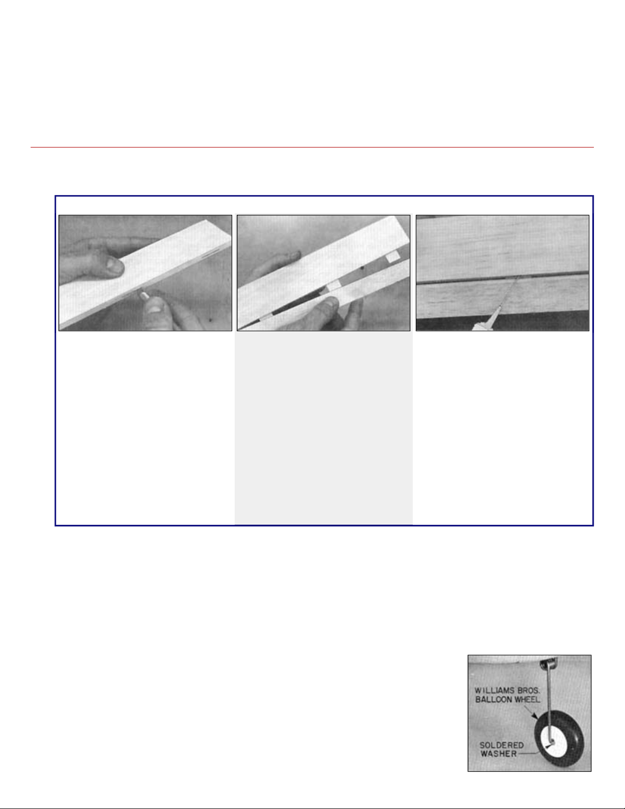
94. Hinge the rudder to the fin (3 hinges) and the elevator to the stabilizer (4 hinges). Follow the instructions below for
Installing Easy Hinges
Using a No. 11 Xcut a slot approximately 1/2" in depth
and slightly wider than the hinge. After
all slots have been cut. insert an Easy
Hinge halfway into each slot in one of
the pieces to be hinged. Then carefully
slide the matching model part onto the
other half of the hinges. You'll find it
easiest to slide the part onto the hinges
at an angle, one hinge at a time.
96. Temporarily position the stabilizer on the fuselage. Refer to the General Alignment Diagram on page 20 of "The Basics of
Radio Control" booklet to properly align the stabilizer. When satisfied, draw cut lines on the bottom of the stabilizer at the
and trailing edge where it contacts the fuselage structure. Now you can glue the stabilizer to the fuselage at the wood-to-
97.
Kwik-Set epoxy. Use a 90 deg. triangle to check the alignment with the stabilizer before it dries.
98. Re-install the main landing gear wires with the nylon straps (see photo 69). Also re-install the
nose gear bearing, the nose wheel steering arm, and the formed nose gear wire. Install
NOTE: the prototype model shown on the box lid used Williams Brothers Smooth Contour
At this point the surface to be hinged is
attached but not glued. Align the two
surfaces and adjust the gap between
them as required. For best control
response, the gap should generally be
as small as possible but big enough to
allow the control surface to move to the
maximum deflection that you require.
Place three or four drops of any brand
cyanoacrylate adhesive (thinnest
variety) directly onto the Easy Hinge in
the gap. You will notice that the glue is
quickly wicked into the slot as it
penetrates both the wood and the
repeat the gluing process on the other
side of each hinge. After the glue has
cured, approximately three minutes, the
joint can be flexed. You may notice a
slight stiffness in the joint. This can be
eliminated by flexing the surface to full
deflection each direction a couple of
dozen times. Don't worry about
shortening the life of the hinge as they
are almost indestructible.
axles so they will be inside the hub. For best appearance and to prevent binding, solder a flat
Page 24
.
the windshield can be glued directly to wood. You can spruce up the appearance of the windshield/fuselage joint using 1/4"
wide striping tape.
battery, switch and antenna.
PRE
-
FLIGHT CHECKOUT
If the nose hangs down below level, the model is nose heavy. If it is only a little nose heavy, don't do anything about it, it
will be okay to go ahead and test fly. If it is more than a little nose heavy, correct by moving the radio batteries out of the
controlling. In the nose heavy positions
Make any changes in the balance position gradually, checking results and the effect of the change on control responses
and the performance of the model in the air.
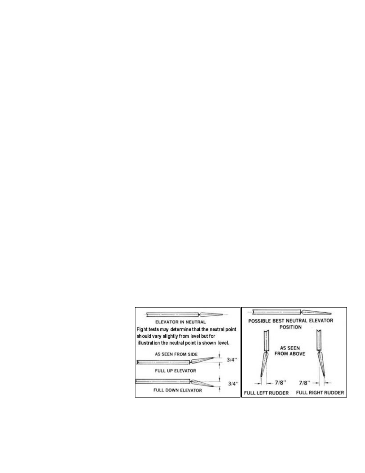
CONTROL MOVEMENTS
size plan. Shift the RC
introduces some nose down trim to keep the model from climbing when the transmitter stick is in the center. The exact best
3/4 throttle, feed in down trim with the transmitter lever until the model flies level.
99. Install the clear plastic windshield using Wilhold RC-56 adhesive or thin CA. If you have painted your model, you can glue
directly to the painted surface. If your model is covered with a plastic film, cut away a narrow strip of the material so that
100. The installation of your engine, fuel tank, and radio equipment is simply a matter of re-installing them as described earlier.
If you haven't done so already, construct the balsa pushrods for the elevator and rudder as shown on the plans. Refer to
"The Basics of Radio Control" and the instructions that came with your radio to complete the installation of your receiver,
Make certain that your model balances and has the correct amount of control movement. It is strongly recommended that
you go through the Pre-Flight Checklist in Chapter 7 of "The Basics of Radio Control" before attempting to fly.
BALANCING
Read "Why Models Must Be Individually Balance" and "Balance is Part of the Trimming Process" boxes on the full-size
plan.
The suggested balance point for the Kadet Senior is shown on the plan. Balance with an empty fuel tank but with all the
other equipment installed and the model completely finished and painted. Suspend the model from the wing tips at the
balance point. It should hang from the finger tips approximately level.
If the tail hangs down at the desired balance point, it is tail heavy. Add lead or weight to the nose or shift the radio
equipment as necessary to get it to sit level. Do not attempt flight in a tail heavy condition.
nose and as far back in the cabin as is necessary to achieve balance. When slightly nose heavy, the model is more
stable and less likely to stall or snap roll from over-elevating. It also cuts down reaction of the model to control
movements and this is good during test and practice flights, to help prevent overyou will probably need more elevator movement to get the nose up in low throttle and glide than in other C.G. positions,
so make sure you have sufficient elevator travel.
Various brands of servos can give
different control movement direction
and amounts of travel. For this reason,
follow the measurements given when
setting the Kadet Senior up for flight
rather than any particular horn hole
drawn on the fulllink to whatever horn hole will produce
the amount of movement shown in the
drawings. Measurements are made at
the trailing edge of the control surface.
Control measurements are suggested as a beginning. Test flights may indicate a need for more or less movement,
depending on individual model differences, center of gravity (C.G.), location etc.
It is not uncommon for the Kadet elevator neutral position to test out to be slightly drooped down from level. This
neutral elevator position for each particular model must be determined during flight testing. With the model flying at about
Page 25
.
Land and observe this position of the elevator. Adjust the elevator pushrod as required to keep this flight checked "neutral"
To Fly The Kadet Senior On A 4 Channel Radio
channels, you would have to make a difficult
just about the same as starting over. The most important thing you are learning in
stick with a particular hand. Forget which control surface is doing the turning on a
will not be too steep. On surfaced or smooth dirt runways less application of elevator will be needed.
off surface is not available, the model can be hand launched by the pilot's assistant. (Do not attempt
it is more important that
angle. If it does not begin to climb after about fifty feet of flight, apply a small amount of up elevator to lift the nose.
wind until about 75 feet of altitude is obtained. Keep first turns gentle
Make your final and complete landing approach while your engine still has plenty of fuel remaining so that the engine is not
if an approach that looks a little high is maintained, chances are good that a spot
-
on landing can be made.
After you get through the first flights, you should begin to "trim" the model's control surfaces. If it is turning to the right, for
its threads. Check in the air for the result. Repeat the process, if necessary, until the trim lever is centered when the model
stick movement alone as you are steering the model along its course.
FLYING
position when the transmitter trim level is returned to the center.
Plug the rudder servo in the fuselage into the receiver outlet marked aileron.Use
of the aileron stick on your radio equipment to operate the rudder will enable you
to develop the proper left and right reactions that will later be needed when
advancing to aileron control, using the same hand. If you plugged the rudder into
the rudder socket when only using 3transition from one hand to the other at the time you advanced to aileron control,
the early stages is an automatic left and right reaction on a particular transmitter
3 channel, assume that the rudder is an aileron.
Be certain to carefully range check your radio equipment and see how it operates with the engine running before
attempting test flights. A lot of problems can be avoided if the engine has been well broken-in and the idle adjustment
perfected on a test block or in another airplane.
Takeoffs from grass fields are easily made if the grass is not too long or the ground too rough. Generally a lot of elevator
application is required for liftoff. Be prepared to relax control pressure partially after becomming airborne so the climbout
If a good smooth taketo hand launch by yourself - instant action on the transmitter may be required.) Holding the front part of the fuselage with
the left hand and under the tail with the right, run into the wind at a fast trot and thrust the model forward with the nose
slightly up in a spear throwing motion. It is not necessary to achieve a lot of velocity in the launch it be released smoothly and with the wings level. The model may dip slightly and then should begin climbing at a slight
Use the rudder to keep the wings level and headed straight into the
and not steeply banked. Stay up wind of the transmitter. Use trim
levers on your radio equipment where necessary to obtain straight
and level flight with the control sticks in neutral position but don't
attemp to make these adjustments until the model is at a good
altitude.
Throttle back at altitude to find out the model characteristics in a gliding condition so that some indication is seen of what
to expect during the landing approach. It is a good idea to make several practice landing approaches at a good altitude to
get the feel of the model for this approaching critical maneuver.
liable to stop before completion of the flight. This will allow application of power if the approach is being under shot. Notice
the percentage of missed landings at an R/C field. Those undershot greatly outnumber those missed by overshooting. So
example, with the stick in neutral, and you must move the transmitter trim lever to the left to make the model fly straight,
then land the model and position the rudder to the left of center by turning the RC link on the pushrod one or two turns on
is flying straight with the stick in neutral. You may find that the reaction of the model is different to high power and low
power, requiring changes in trim lever position during flight, as for a landing approach. This is one of the controls you must
learn to operate during practice flying, but it is not a critical matter at first since these minor corrections can be made with
Page 26
.
RUBBER BANDS ON WING
judgement to the number of rubber bands used. It is a good idea to stretch each new band to its limit before using to locate
form a longer band and then used 10 of these looped
-
together units to hold the wing on, 5 crisscrossed each way.
them from cutting into the wing. This should be done after covering.
It is impossible to give exact directions for every case, since individually built models vary slightly and the engine used also
perfect trim and in the process you can improve your flying.
Remember that different brands of rubber bands have different stretch characteristics. Apply some common sense
any hidden defects. In case of doubt as to whether or not the wing is on securely, add extra rubber bands. Loading a wing
in flight is more destructive than failure of the wing to come off in a hard landing. We looped two no.64 bands together to
Glue a piece of scrap plywood or plastic on the trailing edge at the point the wing rubber bands go over the edge to keep
DON'T WALLOW AROUND THE SKY!
A common mistake made by beginners is to fly around with the model having too much up trim. It climbs out steeply
under full power in this condition (and is probably a safety factor for a rank beginner) and you can level it off by throttling
back on the motor. However, in this over-up condition it wallows around with the nose high, it is hard to turn properly,
and it will not fly into the wind because of low airspeed. The solution is to apply some down trim to the elevator to bring
the nose down and make the model fly more nearly level at cruising power. It may be necessary to drop the elevator a
bit from level by screwing in the RC link on the elevator pushrod to get enough down. The way to learn to do this
trimming process is to experiment with the model in the air and note it's reaction to increased down trim or other
changes. Moving the center of gravity in combination with trim changes can also alter the flying characteristics. For
example, you may find that the balance point specified for test flights will be okay for the first few flights but when the
model is trimmed down to fly more level under cruising power you may find that moving the balance point will give you
better performance.
affects results. But if the model is not flying in a satisfactory manner, then chances are it is not trimmed properly and
should be adjusted accordingly. Do a little tinkering, a bit at a time. This is an instructive way to fathom the mysteries of
Page 27
.
fly there will be no hand switching required other than the change for nose wheel stearing on the ground. If you have a 4 or
more channel radio to put in the Kadet, transition to aileron control can practically be eliminated by hooking the nose wheel
the aileron stick for in
-
the-air turning as you will be doing on 4
-
channel aircraft.
using a 1" diameter prop and/or a lower pitch.
EASING THE TRANSITION FROM 3 TO 4 CHANNEL FLYING
In the first paragraph of the Flying section of the Kadet instructions, we tell you to fly the model by connecting the rudder
servo to the transmitter stick normally used for ailerons so that when you move on to a 4 channel model after learning to
to a 4th servo instead of the Kadet's rudder servo. Then the transmitter rudder stick can be used for ground steering and
FLYING HINT
If, when using large size engines, you have difficulty getting this light wing loading model to land with the throttle in low, try
© Copyright SIG Mfg. Co., Inc.
SIG Mfg. Co., Inc............Montezuma, Iowa 50171-0520
LIMIT OF LIABILITY:
In use of our products, Sig Mfg. Co.'s only obligation shall be to replace such quantity of the product proven to be defective.
User shall determine the suitability of the product for his or her intended use and shall assume all risk and liability in
connection therewith.
 Loading...