

Page 1
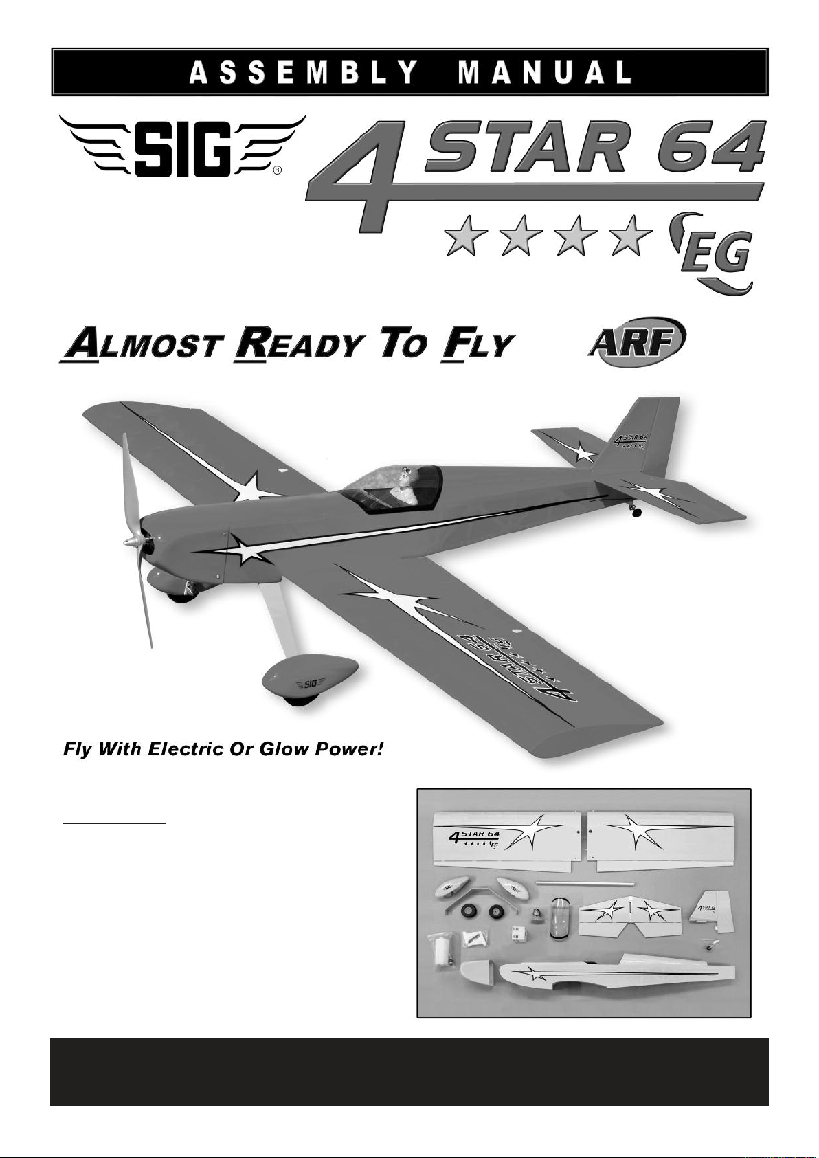
KIT NO.: SIGRC73EGARFR - (red)
SIGRC73EGARFY - (yellow)
SPECIFICATIONS:
Wing Span: 64 in. (1625 mm)
Wing Area: 847 sq.in. (54.6 dm2)
Length: 57 in. (1447 mm)
Flying Weight: 7 - 8.25 lbs. (3175 - 3742 g)
Wing Loading: 19 - 22 oz./sq.ft. (58 - 68 g/dm
Radio Req.: 4-Channel with 5 Standard Servos (glow)
4-Channel with 4 Standard Servos (electric)
Glow Power: 2-Stroke .60 - .75 cu.in. (10.0 - 12.3 cc)
4-Stroke .60 - .90 cu.in. (10.0 - 14.7 cc)
Electric Power: 1200 - 1700 watt Brushless Motor (400-600 kv)
75A Speed Control (ESC)
4-6S 4000 - 5000 mAh Lipo Battery Pack
2
)
SIG MFG. CO., INC. PO Box 520 Montezuma, IA 50171-0520
www.sigmfg.com
© Copyright 2013, SIG Mfg Co., Inc.
Page 2
INTRODUCTION
Congratulations on your purchase of the SIG 4-STAR 64 EG ARF.
We hope you will enjoy this unique fun scale R/C model.
Assembly of your 4-STAR 64 EG ARF is fast and simple when
following the detailed instructions in this manual. We urge you to
read this assembly manual completely before assembly. Familiarize yourself with the parts and the assembly sequences. The
successful assembly and flying of this airplane is your responsibility. If you deviate from these instructions, you may wind-up with
problems later on.
Good luck with the 4-STAR. Let’s get started!
Whatever brand engine you choose, take the time to carefully
break it in according to the manufacturer's instructions. A good
running, reliable engine is a minimum requirement for the enjoyment of this or any R/C model aircraft.
❑ PROPELLER FOR GLOW
Refer to the engine manufacturer’s instructions for recommendations on proper propeller size for their engine. In our experience,
most 2-stroke .60-.75 glow engines will fly the 4-STAR 64 very
nicely with a 12x8 or 13-6 prop.
FOR ELECTRIC POWER
❑ 1200 - 1700 watt BRUSHLESS OUTRUNNER MOTOR
The 4-STAR 64 is designed to be powered with a 1200 to 1700
watt electric brushless outrunner motor. This size motor is sometimes referred to as a "60" class motor to those who like to make
a comparison to a glow motor. Also, the motor you choose should
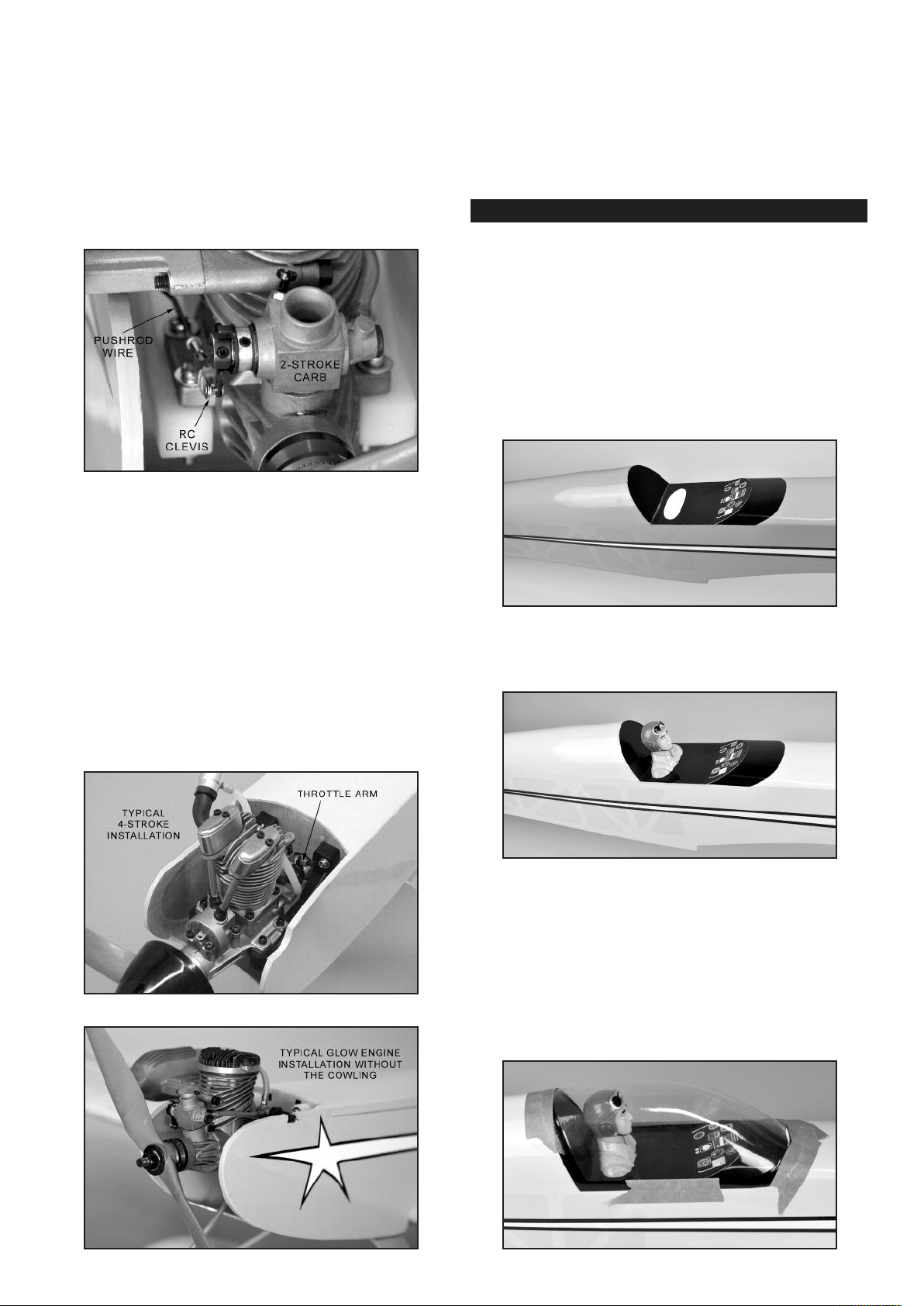
be rated at 400-600 kv, in order to turn an appropriate propeller.
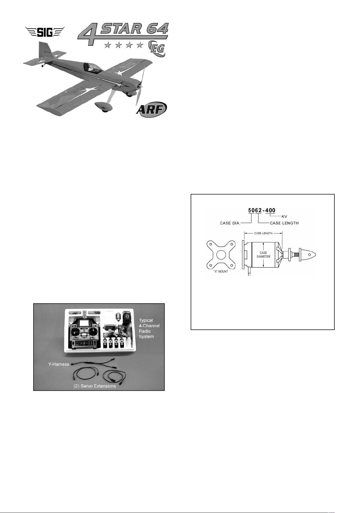
Here is are some motor sizes that work well in the 4-STAR 64:
5030-390
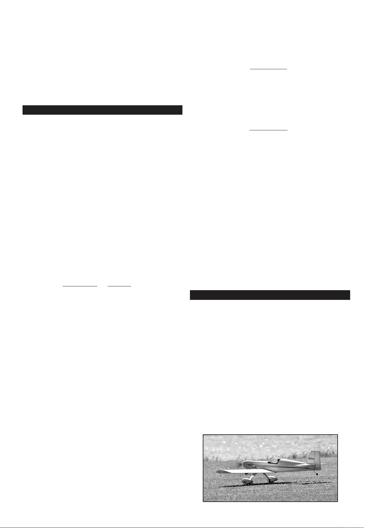
5062-400
5055-650
5065-400
What do those numbers mean?
ADDITIONAL ITEMS YOU WILL NEED TO PURCHASE
In addition to this kit, you will need the following items to complete
your 4-STAR 64 and make it flyable.
❑ RADIO SYSTEM
The Four Star 64 EG requires a standard 4-channel radio system
and four to five standard size servos (number of servos depends
on whether you are using glow or electric power). In addition,
you'll need two 12"- 24” long Servo Extension Chords (actual
length needed will depend on how long the wires are coming off
your servos – plan accordingly), and one Y-Harness Chord for
connection of the two aileron servos to the receiver.
POWER SYSTEM - GLOW OR ELECTRIC?
The biggest decision you will have to make is whether to power
your 4-STAR 64 with a glow engine (2-stroke or 4-stroke) or an
electric motor. We have flown the 4-STAR 64 on a variety of both
types of power systems, and we make the following recommendations based on our successful on-field experience.
FOR GLOW POWER
❑ ENGINE
We recommend the following size engines for the 4-STAR 64.
2-STROKE - .60 to .75 cu. in.
4-STROKE - .60 to .90 cu. in.
NOTE: This numbering system is very common, however there
are exceptions. For instance, some motor manufacturers will
list the actual diameter of the stator (armature) inside the motor
instead of the case diameter. Some may list the length of the
stator inside the motor instead of the case length. Some will
give you both if you dig far enough into their specs. Make sure
you understand the motor manufacturer’s numbering system
when shopping for a motor.
❑ MOTOR MOUNT
A laser-cut plywood adjustable motor mount is included in this kit.
It should work perfectly for any suitable brushless outrunner motor
which has an “X” or “cross” motor mount plate on the back.
❑ 75 amp ESC (Electronic Speed Control)
We use the Castle Creations 75 ESC in all our 4-STAR 64 prototypes. This is an excellent "switching type" ESC that has a built-in
5amp BEC that is safe to use with a 4 or 6 cell lipo battery pack.
We typically see amp draw of 35 to 48 amps, depending on
whether a 4 or 6 cell lipo is being used, and the propeller size.
Important Note: BEC (Battery Eliminator Circuit) allows you to
use the same battery pack to power both your motor and your
radio system, eliminating the normal radio battery pack. When
the single battery pack runs down in flight to a prescribed point,
the BEC circuit in the ESC will shut down the motor and leave
enough power to operate the radio while you land the model. Note
that the BEC feature in some cheaper ESCs does not work with
4 cell and larger lipo battery packs - only 3 cell packs. Check the
manual of your particular ESC to learn if this is true in your case.
If your BEC is not rated for your battery choice you have three op-
2
Page 3

tions. 1) Switch to a lower power setup under the rating of your
BEC; or 2) disable the BEC and install a normal receiver battery
pack to run the radio full time; 3) install an aftermarket BEC that
is properly rated for your setup.
Covering Iron & Trim Seal Tool
Masking Tape
Paper Towels
Alcohol and/or Acetone For Epoxy Clean-up
❑ 4 cell 5000mah or 6 cell 4000mah LIPO BATTERY PACK
You can fly your 4-STAR 64 with a 4 cell (4S1P) or 6 cell (6S1P)
Lipo pack. Pack capacity should be 4000-5000 mah for good flight
duration. A 4 cell pack (14.8 volts) provides flight performance
similar to a .60 glow engine. A 6 cell pack (22.2 volts) provides
flight performance similar to a .75 glow engine. We find that 6s
4000mAh lipo packs provide between 8 to 10 minutes of flight
time, depending on propeller selection and other factors (quality
of pack, throttle management, outside temperature, etc.).
CAUTION: You must match your propeller size to the cell count of
your lipo pack, to avoid drawing too many amps and damaging
your ESC or motor.
❑ PROPELLER
With electric powered models there are many factors that have a
bearing on what propeller to use. The best place to start answering that question is in the instructions that come with your motor.
Another fine source of information is one of the electric flight calculators that are available for you to use free online (there is a
good one on Castle Creations web site).
OUR FLIGHT TEST REPORT
One of our favorite setups for the 4-STAR 64 was a Maxx Products
HC5030-390 motor with a 75 amp ESC, a 6-cell (6S1P) 22.2v lipo
pack, and an APC APC 15x8E propeller. An APC 15x10E propeller also worked well. Both sizes delivered good performance,
very reminiscent of a 2-stroke .75 glow engine. For a starting prop
we recommend the APC 15x8E. Other brand propellers of same
size and similar design can also be used.
This combination gave outstanding flight performance. When
using a 6S 4000 mah lipo, we had flight times around 6-7 minutes,
depending of course on throttle management. A 5000 mah lipo
pack provided between 10 to 12 minutes of flight time. Your results
may vary. Prop size, size and quality of the battery pack, throttle
management, air temperature, etc., all have a bearing on electric
flight performance and flight time. Experiment to find the best
combination for your setup.
❑ BATTERY CHARGER
FOR SAFETY AS WELL AS PERFORMANCE, CHARGE LIPO
BATTERIES ONLY
In addition to providing the critical charging profile needed to
safely charge lipo batteries, a lipo battery charger also includes
the capability of "balancing" the available voltage in the cells, ensuring that the battery pack is at peak capacity at the end of the
charge cycle. This translates to better flight times and a longer
life from the battery pack.
REQUIRED TOOLS
For proper assembly, we suggest you have the following tools and
materials available:
A selection of glues - SIG Thin, Medium, & Thick CA Glue
CA Accelerator, CA Debonder
SIG Kwik-Set 5-Minute Epoxy
Screwdriver Assortment
Pliers - Needle Nose & Flat Nose
Diagonal Wire Cutters
Small Allen Wrench Assortment
Pin Vise for Small Dia. Drill Bits
Hobby Knife with Sharp #11 Blades
Small Power Drill With Selection of Bits
Dremel® Tool With Selection of Sanding & Grinding Bits
Scissors
Sandpaper
WITH A LIPO BATTERY CHARGER!
COMPLETE KIT PARTS LIST
The following is a complete list of all parts contained in this kit.
Before beginning assembly, we suggest that you take the time to
inventory the parts in your kit. Use the check-off boxes ❑ provided in front of each part description. Please also note that the
bolts and nuts required to mount a glow engine to the engine
mounts are not included and must be purchased separately.
❑ (1) Fuselage
❑ (1) Right Wing Panel & Aileron, hinges not glued
❑ (1) Left Wing Panel & Aileron, hinges not glued
❑ (1) Aluminum Tube Main Wing Joiner
❑ (1) Horizontal Stabilizer & Elevator, hinges not glued
❑ (1) Vertical Fin & Rudder, hinges not glued
❑ (1) Fiberglass Cowling
❑ (4) M3 x 10mm Sheet Metal Screws, for cowl mounting
❑ (1) Clear Plastic Canopy
❑ (1) Pilot figure
Main Landing Gear
❑ (1) Aluminum Main Landing Gear
❑ (1) Right Fiberglass Wheel Pant
❑ (1) Left Fiberglass Wheel Pant
❑ (4) M3 x 12mm Socket-Head Bolts, for wheel pants
❑ (3) M4 x 20mm Socket-Head Bolts, for main gear
❑ (3) M4 Split-Ring Lock Washers
❑ (2) 4mm dia. Threaded Axles
❑ (2) 7.6mm Hex Nuts; for axles
❑ (4) 4mm ID Wheels Collars; for axles
❑ (2) 3-1/4” dia. Main Wheels
Tailwheel Assembly
❑ (1) Tailwheel Assembly, with wheel, Formed Wire, Nylon
Bearing, Wheel Collars(2)
❑ (1) Nylon Rudder Steering Control Clasp, with M2 x 15mm
Bolt and M2 Hex Nut
❑ (2) M3 x 12mm Sheet Metal Screws
Electric Motor Mount
❑ (1) Plywood Electric Motor Mount Assembly
❑ (1) Balsa Triangle Stock; for motor mount reinforcement
❑ (4) M4 x 20mm Socket-Head Mounting Bolts
❑ (4) M4 Flat Washers
❑ (4) M4 x 16mm Socket-Head Mounting Bolts
❑ (4) M4 Split-Ring Lock Washers
❑ (4) M4 Blind Nuts
Glow Engine Mounts, Fuel Tank, Throttle Pushrod
❑ (2) Nylon Engine Mounts; for glow engines
❑ (4) M4 x 30mm Mounting Bolts, for motor mount to firewall
❑ (4) M4 Flat Metal Washers, for motor mount to firewall
❑ (1) Fuel Tank
❑ (1) Rubber Stopper Assembly
❑ (1) Fuel Pick-Up Weight (clunk)
❑ (1) Fuel Line Tubing, for inside tank
❑ (1) Metal Pushrod Keeper with Set Screw
❑ (2) Hex Nuts for throttle servo connector
❑ (1) Plywood Fuel Tank Support
❑ (1) 3/8” x 5/8” x 1-1/8” Balsa Block; for fuel tank stop
Misc.
❑ (2) M6.5 x 45 mm Nylon Wing Bolts
❑ (4) Nylon Control Horns; for ail(2), ele(1), rud(1)
❑ (12) M2 x 14mm Screws; for control horns
3
Page 4
❑ (5) Metal RC Clevis; for ail(2), ele(1), rud(1), thr(1)
❑ (5) Small pieces of Fuel Tubing; for R/C clevis keepers
❑ (4) Pushrod Snap Keepers; for ail(2), ele(1), rud(1)
❑ (2) Plastic Cinch Straps
❑ (2) Hook-&-Loop (Velcro®) Straps
❑ (1) Strip of Covering Material
Pushrods
❑ (2) 35.5” long Wire Pushrods, threaded on one end, including
M2 Hex Nuts(2); for elevator & rudder
❑ (2) 7” long Wire Pushrods, threaded on one end, including
M2 Hex Nuts(2); for ailerons
❑ (1) 19.75” long Wire Pushrod, threaded on one end, including
M2 Hex Nut(1); for throttle
❑ (1) Nylon Pushrod Tube, for throttle
COVERING MATERIAL
Your 4-STAR 64 is covered with ORACOVER®, a premium quality
covering made in Germany, and sold in the U.S. by Hanger-9 as
Ultracote®.
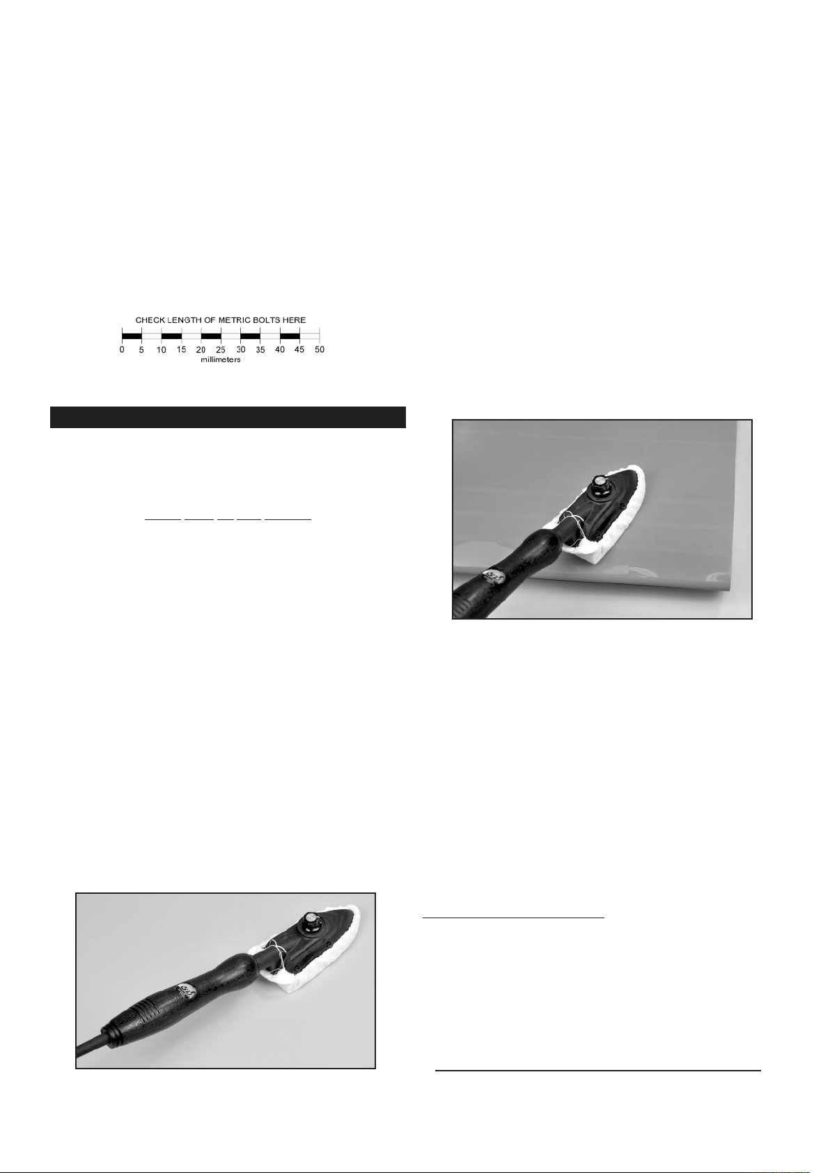
shirt, to prevent scratching the covering as you work.
After covering your iron, the next step is to set the iron to the correct temperature. This is critical for achieving a good result! The
O
iron should be set to about 220
F - 250OF (104OC - 121OC) as
measured on the bottom of the iron using a thermometer.
If you do not have a thermometer, you can find the correct temperature by trial and error. Set your iron to a medium setting.
Glide the iron over some of the covering that is over solid wood,
such as the sheeted wing center section. Observe the covering
to see if any bubbles appear. If bubbles appear, the covering is
getting too hot! Turn down the temperature of the iron and repeat
the test.
If no bubbles appear, turn up the heat slightly and repeat the test.
Keep adjusting until you “zero in” on the correct temperature. Find
the temperature that will get the covering to stick down without
forming bubbles or causing the seams to pull away.
Once your iron is set to the correct temperature, go over the entire
framework of the airplane, making sure that the covering is securely bonded to the structure everywhere the covering comes in
contact with the wood underneath. This takes some time, but is
worth the effort.
Used On Your Airplane
Colors
ORACOVER® #30 Cub Yellow (Ultracote® # HANU884)
or
ORACOVER® #23 Ferrari Red (Ultracote® #HANU866)
If sometime in the future you need replacement covering or
matching paint for repairs, they are available from your local hobby
dealer or online from Hanger-9.
How To Tighten Loose Covering
After you open your 4-STAR 64 and take all the covered parts out
of their plastic bags, the covering may begin to wrinkle. This is
not unusual and is no cause for alarm. Your airplane was built
and covered in a part of the world which has relatively high humidity and therefore, the wood was likely carrying a fair amount
of moisture. When exposed to drier air, the wood typically loses
this moisture, dimensionally "shrinking" in the process. In turn,
this may cause some wrinkles. However, wrinkles are easy to remove by just using a hobby type heat iron.
Caution: Trying to remove the wrinkles by hastily going over them
with a heat gun can lead to more problems. You should take your
time to carefully go over the entire model with a covering iron, as
we will describe.
After you have all the covering secured onto the solid areas, turn
O
the temperature of the iron up to approximately 300
F - 320OF
(149OC - 160OC). This is the correct temperature for shrinking the
covering material.
Use the iron to tighten up any wrinkles in the “open” areas of the
model (no wood underneath the covering). Glide the iron over the
wrinkle for a few seconds, then remove. Repeat until the covering
is tight with no wrinkles.
If wrinkles keep coming back on the tail surfaces, you may need
to “ventilate” the areas between the ribs. Otherwise the air that is
sealed in those relatively small areas will expand when the heat
is applied and actually cause the covering to stretch instead of
shrink. Use a pin to poke a tiny hole in the covering between each
rib, on the bottom of the part. That will let the expanding air escape and the covering to shrink properly.
Caution When Using Heat Guns:
You can also use a hobby-type
heat gun to shrink the covering, but you must be careful around
seams or color joints. Getting too much heat on the seams may
cause them to "creep" or come loose. You must also be careful
when using a heat gun when working around the windshield and
side windows - heat will distort the clear plastic material.
We suggest using a model airplane covering iron for this process.
Cover the iron's shoe with a thin cotton cloth, such as an old t-
Recommended Temperatures:
To adhere the covering - 220OF - 250OF (104OC - 121OC)
To shrink the covering - 300OF - 320OF (149OC - 160OC)
NOTE: In this manual, any references to right or left, refer to your
right or left as if you were seated in the cockpit of the airplane.
4
Page 5
WING ASSEMBLY
The wings are designed as a 2-piece system, with separate right
and left wing panels joined by an aluminum tube wing joiner and
a hardwood locating pin at the rear. Due to the high strength of
the wing joiner tube, the wing panels do not need to be permanently glued together. Gluing them permanently together is optional - your call. The obvious benefit to leaving the wing panels
separate is the fact that they can be easily transported or stored,
requiring a minimum of space.
To help protect your wings during the following steps we recommend that you cover your work surface with a soft cloth or piece
of foam.
INSTALLING THE AILERON SERVOS
For the following steps you will need:
(1) Right Wing Panel
(1) Left Wing Panel
(1) Aluminum Tube Wing Joiner
(2) Servos with Mounting Screws (not furnished)
(2) 12”-24” Servo Extension Chords (not furnished)
(1) Servo Y- Harness (not furnished)
❑ 1) Mount the aileron servos in the bottom of each wing panel.
a) The servo bays are precut for you but you’ll want to double
check the covering around the cutout to make sure it is sealed
down tight.
b) Install the rubber grommets and brass eyelets (supplied with
your radio system) into each aileron servo.
c) Install the control arms on the two aileron servos. The arms
should be at 90 degrees to the servo when the aileron control stick
on the transmitter is in neutral and the transmitter trims are in neutral as well.
d) Before installing the aileron servos in the wing panels you
must attach a servo extension chord to the aileron servo wire. The
typical combined length required is approximately 21”. A 12” extension chord will usually provide sufficient length. Plug the servo
plug into the extension chord and tape the plugs together for
added security.
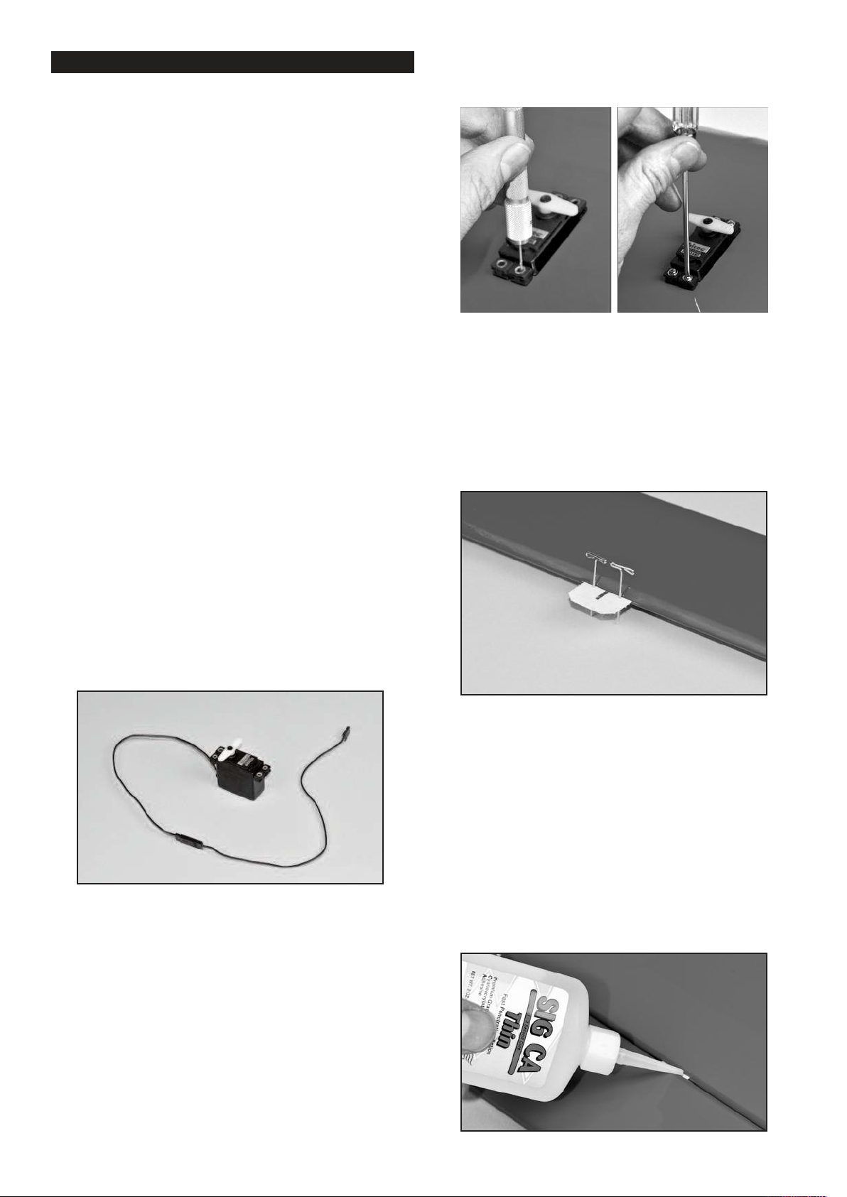
servo mounting screws. Use the screws supplied with your radio
system to mount the servo in place on the servo mount. Repeat
this procedure to mount the servo in the opposite wing panel.
HINGING THE AILERONS
❑ 2) Note that the CA Hinges are installed, but not yet glued, in
the ailerons and wing panels. The installation process for the
hinges is the same for all of the control surfaces on this model.
a) If you removed the ailerons and hinges from the wing panels
when you tightened the covering material, reinstall them now.
First insert the five CA Hinges into the slots in the aileron. Put
two pins in the center of each hinge, up against the leading edge
of the aileron, to keep the hinges centered during the next step.
e) Holding the wing panel with the wingtip UP, drop the end of
the extension chord into the servo mount cutout and then thru the
openings in the wing ribs, working it towards to the center end of
the wing panel. The plug on the end of the extension chord will
occasionally get hung up on the ribs, however by turning or gently
shaking the wing panel you can get it to fall through the openings
in the ribs, until it emerges at the end rib. Once you’ve got the
plug to the end rib, direct it through the round hole in the bottom
surface of the wing panel. By that time, the servo itself should be
next to the servo mount cutout and ready for mounting.
f) Fit the servo into the servo mount in the wing panel, (note
that the servo is positioned so that the servo arm is at the forward
end toward the wing leading edge). Take up any slack in the servo
chord as you insert the servo in the mount. Use a pin vise and a
small drill bit to drill small pilot holes in the servo mount for the
b) Now carefully insert the exposed portion of the five hinges
into the trailing edge of the wing. You will find it easiest to slide
the hinges into the slots at angle, one hinge at a time, instead of
trying to push it straight onto all the hinges at once.
c) Adjust the aileron so that the tip of the aileron is flush with
the wing tip. The ailerons should be tight against the pins in the
hinges to minimize the gap between the wing and the aileron. The
aileron is now in the proper position for permanently gluing them
in place with thin CA glue.
d) Flex the aileron down and hold it in this position. Remove
the pins from one hinge and then carefully apply 3-4 drops of Thin
CA glue directly onto the hinge in the gap. You will notice that the
glue is quickly wicked into the slot as it penetrates both the wood
and the hinge. We suggest using a fine tipped applicator on the
glue bottle to better control the flow of glue.
5
Page 6
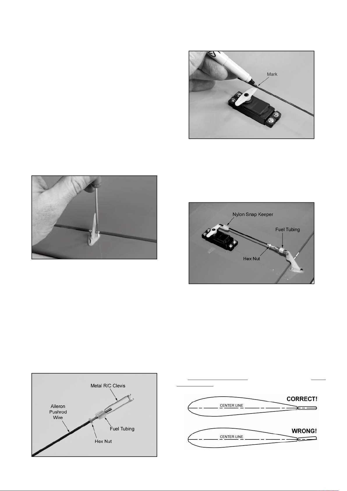
e) Turn the part over and glue the other side of the hinge. Continue this process until you have glued both sides of all the hinges!
Keep a rag handy to wipe off any excess Thin CA glue. (If you
get some glue smears on the plastic covering, don't worry about
them right now. Once all the hinging is done, you can clean the
smears off the covering with CA Debonder).
f) Let the glue dry 10-15 minutes before flexing the hinges. At
first you might notice a little stiffness in the joint. This will go away
after the hinges have been flexed back and forth a couple dozen
times.
INSTALL AILERON CONTROL HORNS & PUSHRODS
From the kit contents locate:
(2) Nylon Control Horns
(6) M2 x 14 mm Screws
(2) 7” long Pushrod Wires with M2 Hex Nut
(2) Metal R/C Clevis
(2) Pushrod Snap Keepers
(2) small pieces of Fuel Tubing
horn. Lay the other end of the pushrod wire over the outer hole
in the servo arm. Use a felt tip pen to mark the wire where it
crosses the hole. Use a pair of pliers to put a sharp 90-degree
bend in the wire at the mark.
❑ 3) Look closely and you will see three holes pre-drilled in the
bottom of the ailerons for mounting the nylon control horns. Screw
the control horn in position on the bottom of the aileron using three
M2 x 14mm screws.
When the tips of the screws begin to emerge at the top surface of
the aileron, add the control horn's nylon retaining plate. The
aileron will be sandwiched between the control horn on the bottom
and the retaining plate on the top. Continue turning in the screws
until the horn and retaining plate are snug against both surfaces
of the aileron. Do not over tighten the screws and crush the wood.
The excess length of the screws that is extending past the retaining plate can be cut off with a pair of side cutting pliers or ground
down with a rotary tool with a cutoff disc.
❑ 4) Next assemble and install the aileron pushrods.
a) Slide a short piece of Fuel Tubing onto the small end of the
Metal R/C Clevis. Screw the Hex Nut on the Aileron Pushrod Wire
all the way up to the end of the threads. Then screw the metal
clevis halfway onto the threaded end of the Aileron Pushrod Wire.
c) Insert the bent end of the pushrod into the servo arm, from
the top. Note: You will most likely need to use a 1/16” dia. drill to
open the hole in the servo arm to accept the pushrod wire.
d) Mark and cut off the excess end of the pushrod wire, leaving
1/8” of wire protruding below the bottom of the servo arm.
e) Clip a Nylon Snap Keeper in place on the servo end of the
pushrod wire. Snap the free end of the keeper up and over the
protruding end of the pushrod wire, underneath the servo arm.
f) Check that the aileron servo is in neutral position and adjust
the metal clevis as needed to get the aileron in neutral position.
VERY IMPORTANT
CORRECT NEUTRAL POSITION FOR 4-STAR AILERONS
Adjusting the neutral position of the ailerons of the 4-STAR is a
bit different than most models, due to the 4-STAR unique airfoil
shape. The 4-STAR airfoil is flat on the bottom from the main spar
back to the trailing edge of the wing panel. DO NOT line the
aileron up with this flat bottom portion of the airfoil. That would
set the both ailerons too high and be detrimental to the flight characteristics of the airplane.
b) Clip the metal clevis into the last hole in the nylon control
The center line of the ailerons
line of the airfoil, as shown in this drawing.
g) Once the ailerons are properly adjusted, insure that the
metal clevis can’t open up and come loose from the control horn
6
must be lined up with the center
Page 7
by sliding the piece of Fuel Tubing over the arms of the clevis.
Also tighten the M2 Hex Nut up against the back of the clevis.
FUSELAGE ASSEMBLY
INSTALL THE MAIN LANDING GEAR
Locate the following parts from the kit contents:
(1) Fuselage
(2) Aluminum Main Landing Gear
(3) M4 x 20mm Socket-Head Bolts
(3) M4 Split-Ring Lock Washers
(2) 3-1/4" dia. Main Wheels
(2) 4mm dia. Threaded Axles
(4) 7.6mm Hex Nuts; for axles
(4) 4mm ID Wheels Collars; for axles
(1) Right Fiberglass Wheel Pant
(1) Left Fiberglass Wheel Pant
(4) M3 x 12mm Socket-Head Bolts
NOTE: We suggest you use a thread locking liquid (like Locktite®)
on all bolts and nuts used in the assembly of the landing gear.
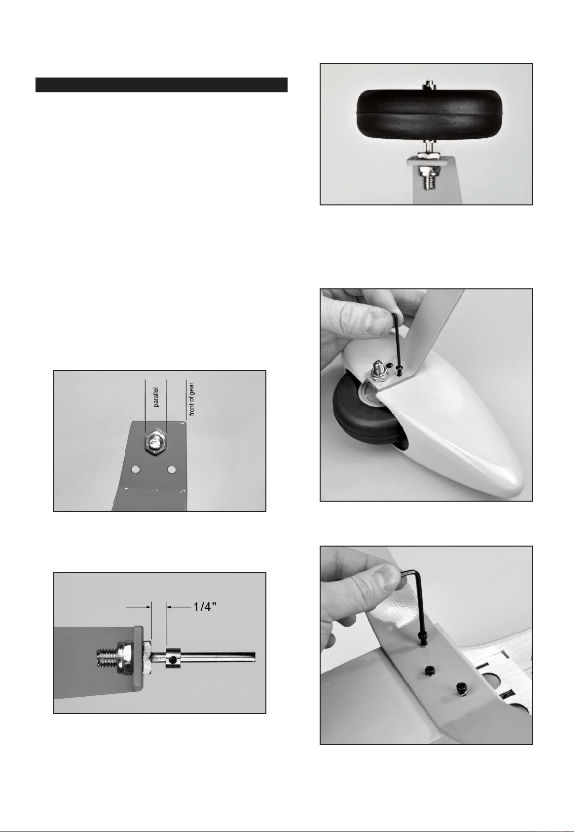
❑ 5) Install a Threaded Axle into the large hole of the landing gear
leg, with the plain end of the axle shaft pointing to the outside.
Secure the axle with the two 7.6mm Hex Nuts. When tightening
the nuts, keep the flats of the nut on the axle side of the gear leg
parallel to the front edge of the leg - see photo. This allows the
hex nut to fit inside the narrow notch in the wheel pants when they
are added later.
wheel. Leave a small gap between it and the wheel, so the wheel
will turn freely, and then tighten the wheel collar set screw.
❑ 9) Check the orientation of the landing gear to make sure you
know which way is forward. The two outer holes for mounting the
gear to the fuselage go to the front. Then test fit the wheel pants
over the wheels and line up the predrilled mounting holes. Secure
the wheel pants in place with two M3 x 12mm socket head bolts
for each pant.
❑ 6) Slide a 4mm Wheel Collar onto the axle shaft, but leave approximately 1/4” of space between it and the nut, to provide proper
spacing of the wheel in the wheel pant. Tighten the wheel collar
set screw securely.
❑ 7) Slide the wheel on the axle and test to make sure it spins
freely on the axle. Next slide one of the Main Wheels onto the
axle and test to make sure it spins freely. If it does not turn freely,
drill out the plastic hub of the wheel with an 11/64" or #17 drill bit.
❑ 8) Slide a second wheel collar onto the axle and up to the
❑ 10) Using three M4 x 20mm Socket-Head Bolts and three M4
Split-Ring Lock Washers attach the landing gear to the fuselage.
7
Page 8
TAIL SURFACE & TAILWHEEL INSTALLATION
For the following steps you will need:
(1) Fuselage
(1) Wing
(1) Stabilizer & Elevator set
(1) Vertical Fin & Rudder Set
(2) M6.5 Nylon Wing Bolts
(1) Tailwheel assembly, including Wheel and Wheel Collars
(2) M3 x 12mm Screws
(1) Nylon Rudder Steering Clasp with Bolt and Hex Nut
(2) Nylon Control Horns
(6) M2 x 14mm Sheet Metal Screws
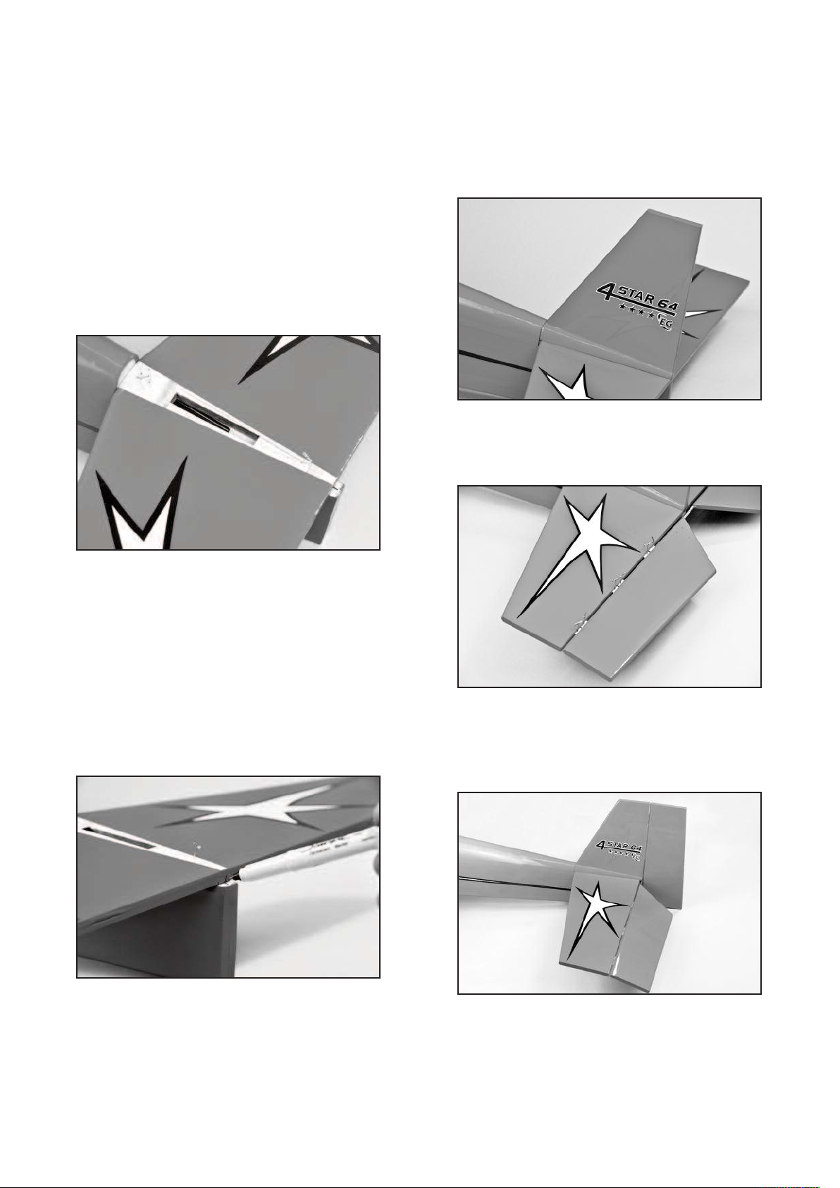
❑ 11) Remove the elevator and hinges from the horizontal stab
and set them aside for now. Test fit the stabilizer on the fuselage.
Notice that the covering has been removed from both the fuselage
and horizontal stabilizer where they will mate together. Eyeball
the location of the horizontal stabilizer and pin it in place.
aside for now. Test fit the fin in place on top of the stabilizer.
Check to see that the fin sits flush and perpendicular to the stabilizer. When satisfied with the fit, glue the fin in place using slow
drying epoxy glue. Apply a thin coat of glue to the bottom of the
fin and to the exposed wood on the stab. With the fin in place,
sight the model from the front to make sure the fin is absolutely
90 degrees upright to the stab. If needed, use a little masking tape
to hold it in alignment. Wipe off any excess glue rubbing alcohol
and a soft paper towel.
❑ 15) Just like the aileron hinges, the elevator hinges are factory
installed, but not yet glued. Hinge the elevator assembly to the
stabilizer, using the same techniques you did for the ailerons on
page 5 of this manual. Let the hinges dry before flexing them.
❑ 12) Bolt the wing in place on the fuselage with the Nylon Wing
Bolts provided. Carefully check the alignment of the stabilizer to
the wing.
a) First view the model from directly in front. Check to see if
the stabilizer is level with the wing. You should find it to be very
close. If necessary use a sanding block to fine tune the stabilizer
platform to level the stabilizer to the wing.
b) Next use a tape measure to measure the distance from each
stab tip to the back edge of the wing - the distance should be
equal on both sides. Adjust if necessary.
c) Mark the front and rear of the stabilizer with a felt pen for
alignment guides. You can now remove the pins and lift up the
stabilizer for gluing.
❑ 16) The rudder is now hinged to the fin and to the rear of the
fuselage using the same techniques you did for the other hinges.
Make sure to line up the top of the rudder flush with the top of the
fin. This will ensure the tail wheel bracket lines up correctly. Let
the hinges dry adequately before proceeding.
❑ 13) The horizontal stabilizer is now glued in place into the rear
of the fuselage. We suggest using slow drying epoxy glue for this
job to allow time to position the stab accurately and make any final
adjustments that might be needed. Apply the glue to both sides
and reset the stab in place. Use pins to hold it in place. Re-check
the alignment. Wipe away any excess epoxy with rubbing alcohol
and a soft paper towel. Allow the glue to set completely.
❑ 14) Pull the Fin and Rudder apart set the rudder and hinges
❑ 17) Mount the Tailwheel assembly in place on the lower rear
end of the fuselage, using two M3 x 12mm screws. Note that
there are two pilot holes already in the fuselage for the screws.
❑ 18) Adjust the wheel collar shown to set the height of the tailwheel wire. Then check to see if the long steering leg of the tailwheel wire is parallel to the bottom of the rudder. The wire may
need to be tweaked slightly to make it parallel.
8
Page 9
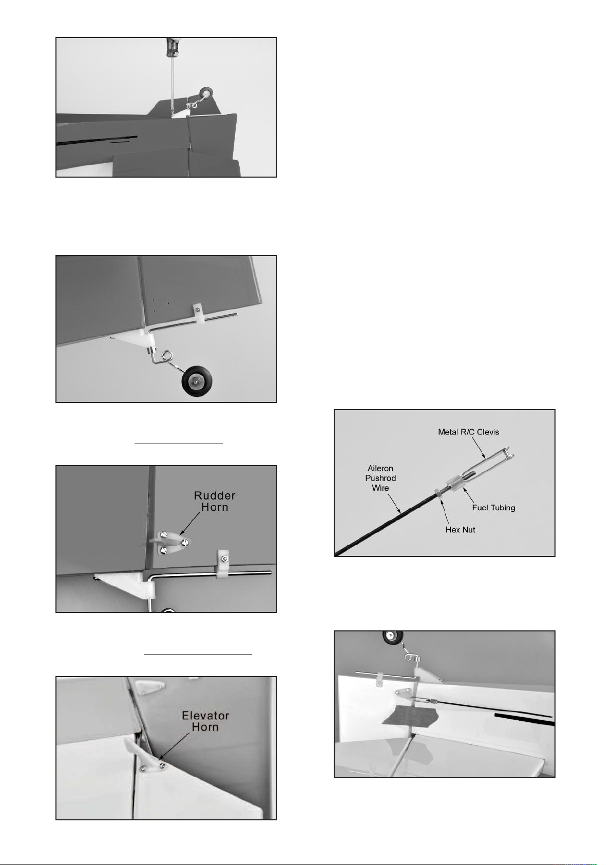
❑ 19) Slide the Nylon Rudder Steering Clasp onto the bottom of
the rudder and onto the tailwheel wire at the same time. Locate
the clasp at the halfway point on the wire, and then drill a hole for
the M2 x 15mm Bolt. Insert the bolt through the hole and tighten
down the M2 Hex Nut to clamp the bracket in place.
ELEVATOR & RUDDER CONTROLS
For this section you will need:
(1) Fuselage Assembly
(2) 35.5" long Wire Pushrods with M2 Hex Nut
(2) Metal RC Clevis
(2) small pieces of Fuel Tubing
(2) Pushrod Snap Keepers
(1) Radio Receiver (not furnished)
(2) Servos with Mounting Screws (not furnished)
❑ 22) Install the rudder and elevator servos inside the fuselage in
the built-in plywood radio mounting tray. Note that the rudder
servo goes on the right side of the airplane, and the elevator servo
goes on the left side. (The servo opening in the center is for the
throttle servo in a glow installation.) Be sure to drill pilot holes
through the plywood tray for the mounting servo mounting screws.
❑ 23) Mount your receiver in a place of your choosing. If using a
glow engine it is recommended that you wrap the receiver in foam
rubber to protect it from vibrations.
❑ 24) If you are using a receiver battery pack, mount your on/off
switch in the fuselage side. Note that there are precut holes in
the fuselage sides, underneath the covering material, for either a
standard size switch or a super switch with built-in charging plug.
Cut away the covering over the hole that fits your switch and
mount using the screw supplied with your switch.
❑ 20) Look closely and you will find three holes pre-drilled near
the bottom of the rudder for mounting a nylon control horn. Install
the control horn on the left side of the rudder
plate on the right, using three M2 x 14mm screws.
❑ 21) Look closely and you will find three holes pre-drilled in one
of the elevators for mounting a nylon control horn. Screw the control horn in position on the bottom of the right elevator
M2 x 14mm screws.
, with the retaining
using three
❑ 25) Assemble and install the rudder pushrod.
a) First slide a small piece of Fuel Tubing onto the small end of
the Metal R/C Clevis. Next screw the Hex Nut that is on the
Pushrod Wire all the way up to the end of the threads. Then screw
the metal clevis halfway onto the threads.
b) Locate the precut pushrod exit hole for the rudder on the left
side of the fuselage at the back of the plane. Slide the pushrod
into the sleeve and attach the clevis to the control horn. Center
the rudder and hold it in place with a couple pieces of tape so it
cannot move.
c) Inside the fuselage, hold the pushrod wire over the rudder
servo output arm and mark the wire where it crosses over the
outer hole in the servo arm.
9
Page 10
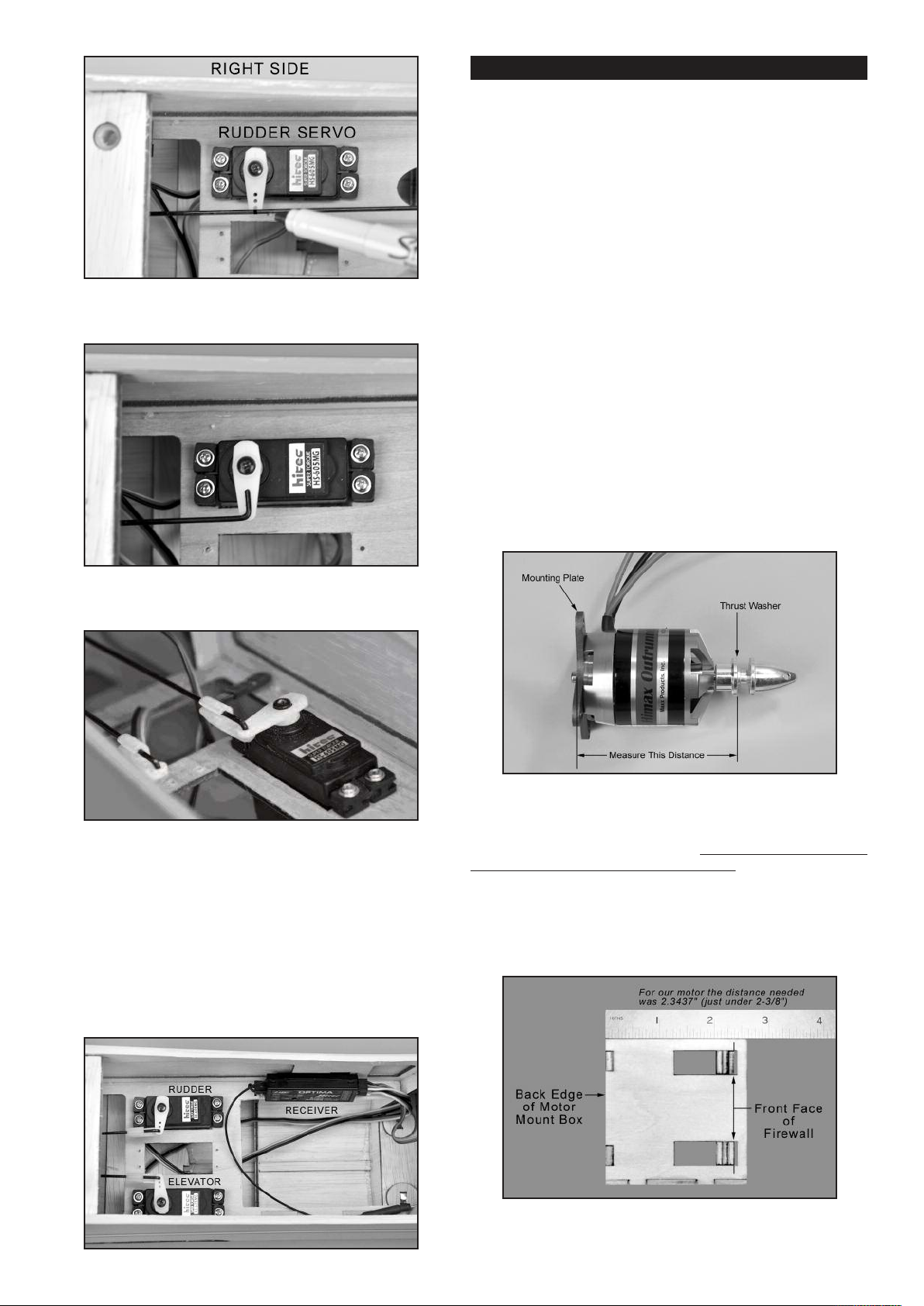
d) Cut the wire ¼” past the mark and then put a 90-degree
bend in the wire.
ELECTRIC POWER SYSTEM
Skip this section if your using a glow engine power setup
For this section you will the Fuselage and:
(1) Fiberglass Cowling
(4) M3 x 10mm Screws
(1) Plywood Electric Motor Mount
(1) Balsa Triangle Stock
(4) M4 x 20mm Socket-Head Bolts
(4) M4 Flat Metal Washers
(4) M4 x 16mm Socket-Head Bolts
(4) M4 Split-Ring Lock Washers
(4) M4 Blind Nuts
(2) Hook-&-Loop (Velcro®) Straps
(1) Electric Motor, ESC, Prop, Lipo Battery (not furnished)
NOTE: The mounting of the electric motor in the 4-STAR 64 assumes that your motor has a typical "X" or "cross" mounting plate
on the back of the motor. Also note that the firewall portion of the
laser-cut plywood motor mount is adjustable fore and aft to accommodate different length motors. Next we will determine where
you should set the firewall for your particular motor.
❑ 27) Assemble your motor according to the manufacturer's instructions. Then carefully measure the distance from the back of
the mounting plate to the front of the thrust washer*.
*
The “thrust washer” is the part of the prop adaptor where the
back of the propeller will be located.
e) Push the wire through the outer hole in the servo output arm
and secure with a nylon pushrod snap keeper.
f) Make sure that the rudder servo is in neutral position and
then adjust the metal clevis at the tail end as needed to get the
rudder in perfect neutral position.
g) After the rudder is properly adjusted, insure that the metal
clevis can’t open up and come loose from the control horn by sliding the small piece of fuel tubing over the arms of the clevis. Also
tighten the M2 Hex Nut up against the back of the clevis
❑ 26) Locate the pre-cut pushrod exit hole for the elevator on the
right side of the fuselage at the back of the plane and repeat step
25) in its entirety to install the elevator pushrod.
❑ 28) For the 4-STAR 64, you need a distance from the back edge
of the motor mount to the motor’s thrust washer to end up exactly
5-9/16” (5.5625”). This is important so the cowling will fit properly.
a) So what you need to do is to subtract the measurement
taken in the previous step (27) from 5.5625”. The result is the distance you need to set the front of the firewall from the back edge
of the plywood motor mount box. (With the motor we are using in
these photos, the motor measurement is 3.2188”. So 5.5625”
minus 3.2188” = 2.3437”. Your result may be different depending
on your motor.)
b) Carefully measure and mark the distance determined in the
previous step from the back edge of the motor mount box towards
10
Page 11
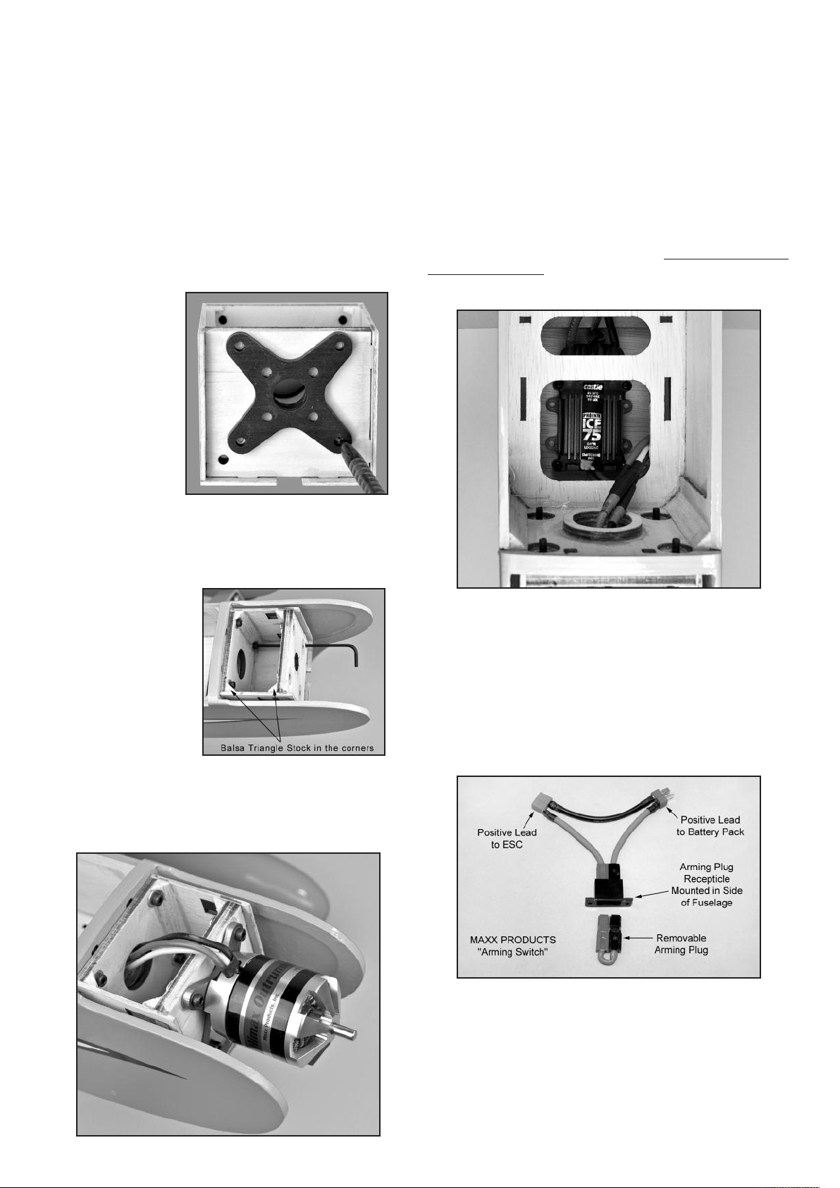
the front. Do this along side each of the adjustment slots on both
sides of the box (four marks total).
c) After you have all four slots marked, carefully align the front
face of the firewall to line up with the marks. Make sure you end
up with the firewall straight and square in the box. If it is not,
recheck your marks and adjust as necessary.
d) Tack glue the firewall in place. Recheck once more to make
sure that the front of the firewall is at the correct distance from the
back of the motor mount box. That distance plus the length of
your motor must equal 5-9/16” (5.5625”). When satisfied it is correct, glue the firewall securely to the rest of the motor mount box.
❑ 29) Remove the X mount plate from the back of your motor and
center it on the firewall. Once you are sure it is properly located,
mark the mounting holes with a pencil. Remove the X mount and
drill out the mounting
holes with a 7/32"
dia. drill. Install four
M4 Blind Nuts in the
holes, on the back
side of the firewall.
Put a couple drops of
glue on the flanges
of the blind nuts to
secure them to the
plywood. Be careful
not to get any of the
glue in the threads.
❑ 33) Install your ESC
a) Solder appropriate battery connectors (not supplied) to the
battery leads of your ESC.
b) The ESC will sit underneath the battery tray behind the firewall. If you are using a thinner ESC you can slide the ESC into
the bay via the opening in the firewall below the electric motor box.
If you are using a thick ESC with a heat sink you will need to cut
open the front slot in the battery tray. Secure the ESC in place
with double-sided tape or Velcro® tape (neither of these are provided).
c) Now route the ESC’s servo wire back to the receiver and
plug it in.
d) Connect the ESC's motor wires to the motor. Operate the
motor and check the direction of rotation. Always do this without
a propeller attached! If you need to reverse the rotation, refer to
the instructions that came with the motor and ESC.
❑ 30) Locate the piece of balsa triangle stock provided. Measure,
cut and install pieces of triangle stock to reinforce all the corner
joints inside the motor mount box.
❑ 31) Bolt the plywood
motor mount box to the
fuselage with M4 x
20mm Socket-Head
Bolts and M4 Flat
Metal Washers. Note
that two access holes
have been cut in the
bottom corners of the
firewall to allow access
for your hex wrench.
❑ 32) If you have not already re-attached the X mount plate to the
back of your motor, do so now. Then use (4) M4 x 16mm SocketHead Mounting Bolts and Lock Washers to bolt your motor in
place on the plywood motor mount box.
SAFETY ISSUE: We strongly recommend the use of an “arming
switch” for your motor installation. With an arming switch you can
install your battery pack in the airplane and hook up the wires
without danger of the motor starting. The arming switch keeps
the electricity away from the motor until you “arm” it when you are
ready to takeoff. The most common arming switches are a simple
external plug that puts a break in the positive battery lead to the
motor, such as the Maxx Products Arming Switch shown below.
There are also arming switches built into some of the advanced
ESCs now on the market.
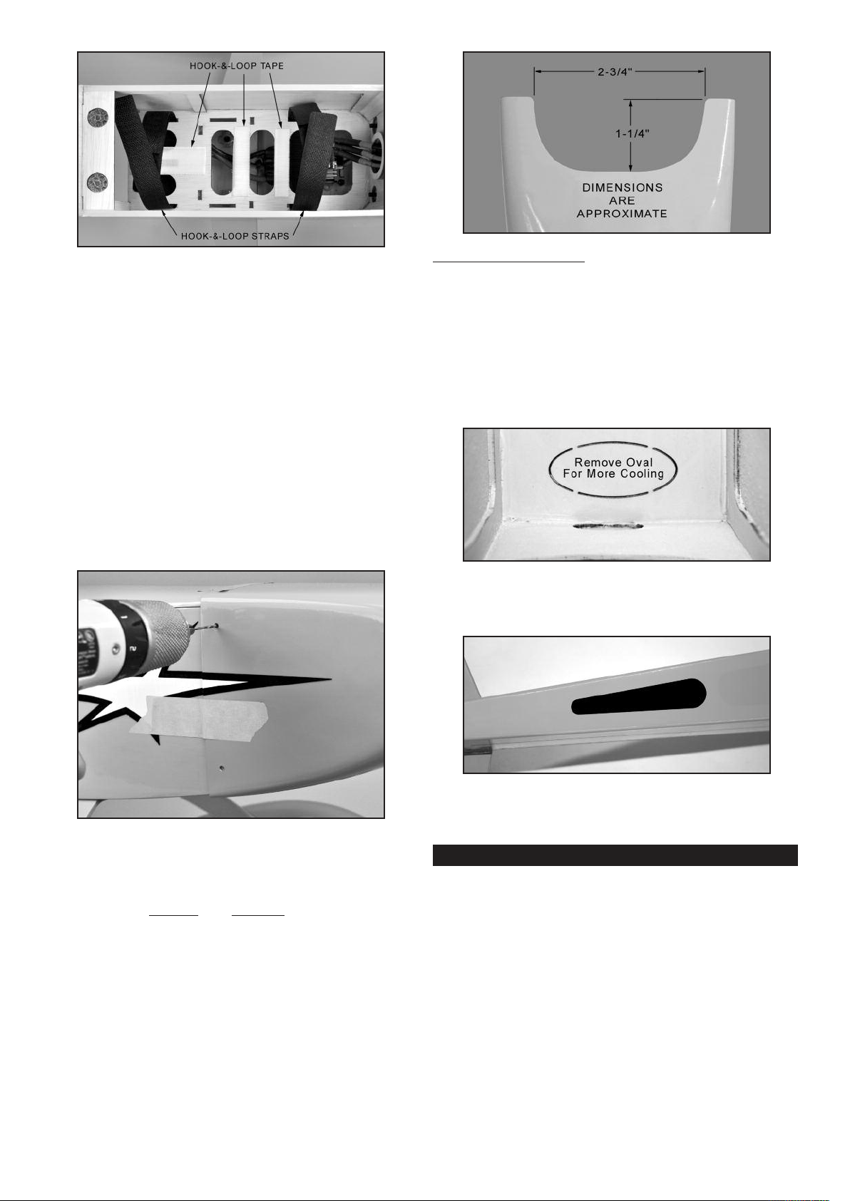
❑ 34) Two hook-&-loop (Velcro®) straps are provided to hold your
lipo battery pack in place inside the fuselage. Feed the straps
through the slots in one side of the plywood battery tray, and then
up through the other side, as shown in the next photo.
In addition to the two straps, it is a good idea to use hook-&-loop
tape (not furnished) on both the bottom of your battery pack and
on the top surface of the plywood battery tray, to make sure the
battery pack will not move around during aerobatics.
11
Page 12
❑ 35) Mount the cowling on the fuselage with the four M3 x 10mm
Screws provided. Notice that the holes for the four cowl mounting
screws are already pre-drilled in the cowling - two on each side.
a) First test fit the cowling on the fuselage. As you pass it over
the motor, make sure all the wires are out of the way. Carefully
adjust the exact position of the cowling. Make sure you have adequate clearance between the front of the cowl and the back of
the propeller, and that the prop shaft is centered in the hole. Use
low tack tape to hold the cowling in place for the next step.
b) Use a 5/64" or #45 bit to drill a pilot hole for the top left cowl
mounting screw. Center the drill in the hole in the cowling and
drill into the fuselage side. Install an M3 x 10mm screw in the pilot
hole - do not over-tighten the screw.
c) Recheck the position of the cowling and make any adjustments needed to get it back in position.
d) Now drill another pilot hole for the upper screw on the other
side of the cowling. Install the screw.
e) Repeat this process to install the two bottom cowl mounting
screws. Remove all the tape.
Additional Cooling Options:
ESC or battery pack need additional cooling. We have not found
that to be necessary with our prototype 4-STAR 64, but it could
happen in some cases with different motors, props, etc. If you
need more cooling air flowing over the ESC and battery, here are
a couple good options.
Option #1) To get more air flowing into the fuselage, you can
open another hole in the firewall. Near the bottom of the firewall
you will find an oval shape that is only partially cut through. It is
easy to finish the cut and remove the oval, which will allow air to
flow directly over the ESC under the battery tray.
Option #2) If you need more air flowing out of the fuselage,
make an air exit hole in the bottom rear of the fuselage, back near
the tail, as shown here.
You may find after test flying that your
❑ 36) COOLING IS IMPORTANT!
With a fully cowled motor, it is very important to make sure your
power system is getting proper cooling. Air flowing into the front
of the cowling must have a place to exit the cowl. In fact it’s best
to have more air exit area
flow through the cowling - an actual suction effect - drawing the
heated air out of the cowling so that more cool air can come in.
This positive air flow keeps your motor running cool. We recommend that you make a simple opening at the bottom rear edge of
the cowling as shown in the next photo, to provide additional air
exit area. The exact dimensions are not critical.
Note: A Dremel® Tool, or similar rotary hand-tool, with an assortment of bits is without a doubt the best tool to use for making
cutout in the fiberglass cowling. However, if you do not have access to such a tool, you can cut the opening with a drill, a hobby
knife, and a sanding block. First first drill a series of almost touching 1/8” holes inside the pattern lines; then use the knife to cut
through the connecting material between each hole; and finally
finish the edges of the opening with the file or a sanding block.
than inlet area to create a positive air
❑ 37) Mount a suitable propeller (not furnished) on your motor.
Be sure to balance the propeller before installation.
GLOW POWER SYSTEM
Skip this section if your using an electric power setup
For this section you will need the Fuselage and:
(2) Nylon Engine Mounts
(4) M4 x 30mm Mounting Bolts
(4) M4 Flat Metal Washers
(1) Fuel Tank
(1) Rubber Stopper Assembly
(1) Fuel Pick-Up Weight (clunk)
(1) Fuel Line Tubing for inside tank
(1) Plywood Fuel Tank Support
(1) Balsa Block for Fuel Tank Stop
(1) Nylon Throttle Pushrod Tube
(1) 19.75" long Wire Pushrod with M2 Hex Nut
(1) Metal Pushrod Keeper with Set Screw and Hex Nuts
(1) Metal RC Clevis
(1) small piece of Fuel Tubing for clevis
(2) Hook-&-Loop (Velcro®) Straps
12
Page 13
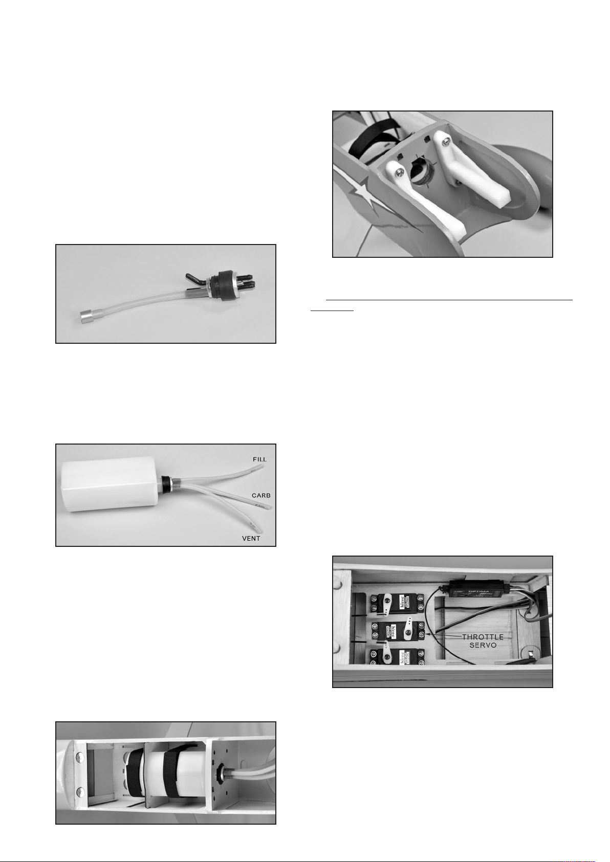
❑ 38) Start by putting the Fuel Tank together.
a) Locate the Rubber Stopper Assembly. There are three nylon
tubes going through the rubber stopper. Orient the stopper so
that one of the tubes is towards the top and then bend that tube
up at a 45-degree angle. Do not apply heat to the tube - it will
bend without heat. Just overbend it to nearly 90-degrees and then
let it relax, to see where it will end up. Repeat if necessary until
the tube will stay at 45-degrees.
b) Attach the metal Fuel Pick-Up Weight on one end of the silicone Fuel Line Tubing that goes inside the tank. Cut the other
end of the fuel line tubing to a length that will allow the clunk to
reach the back of the tank, without getting stuck on the walls of
the tank. Test fit in the tank and adjust as necessary. With the
stopper assembly in place, the fuel clunk should sit just in front of
the rear of the tank and move freely inside the tank. If not pull the
assembly back out and trim the tubing back until the stopper
moves freely. The top of the vent tube should rest just below the
top of the tank. It should not touch the top of the tank.
f) Glue the balsa block fuel tank stop in place on the plywood
tank tray, up against the rear end of the tank.
❑ 40) Bolt the two Nylon Engine Mounts on the front of the firewall, using M4 x 30mm Bolts and M4 Flat Washers provided. Note
that the blind nuts are already installed in the back of the firewall.
❑ 41) Set your engine in place on the beams of the engine
mounts. Slide the engine forward or aft on the engine mounts until
the front of the engine's thrust washer is 5-9/16" from the front of
the firewall. Double check to make sure that the engine is pointing
exactly straight forward, and then mark the locations of the engine
mounting holes onto the beams of the engine mounts, using a
center punch or sharpened nail.
c) Once you are satisfied with the fit of both the fuel clunk line
and the vent line you can tighten the machine screw to expand
the rubber stopper and seal the stopper in the tank. Do not over
tighten the screw as it can cause the tank to split. Attach three 6inch lengths of silicone fuel tubing (not furnished) to the tank and
label them appropriately as FILL, CARB, and VENT so you can
identify them after the tank is installed in the airplane.
❑ 39) Install the tank in the fuselage.
a) Install the two hook-&-loop (Velcro®) straps through the
slots in the plywood fuel tank tray. You may find it useful to use a
thin straight edge such as a small ruler inserted into the second
slot to help guide the strap back up to the top of the tray.
b) Set the plywood fuel tank support in place, but do not glue.
c) Install the fuel tank through the back of the plywood tank
support. Push the tank all the way up to the back of the firewall,
pulling the 3 fuel lines through the firewall as you go.
d) Strap the tank in place with the hook-&-loop straps.
e) Glue the plywood fuel tank support in place, inserting its
bottom tabs into the slots in the plywood fuel tank tray. We suggest you only spot glue the tank support in place at the top so it
can be removed later if you ever need to service the fuel tank.
❑ 42) Now set your engine aside and unbolt the engine mounts
from the firewall. Drill clearance holes for your engine mounting
bolts all the way thru the engine mount beams at the four locations
you marked in the previous step.
tap these engine mounts. Doing so may weaken them and
cause failure. Use steel mounting bolts, flat washers, and nylon
insert lock nuts (not provided).
Drill 5/32" dia. holes if you are using 6-32 mounting bolts.
TIP: Secure the engine mounts in a vise while you drill the holes.
If at all possible use a drill press instead of a hand drill - the job
will be much easier and the holes will be straighter.
❑ 43) 2-STROKE THROTTLE PUSHROD
a) Mount your throttle servo in the middle opening of the servo
tray in the fuselage.
b) The supplied throttle pushrod assembly consists of a wire
pushrod running inside a nylon pushrod tube. On the threaded
end of the pushrod you will have a metal RC clevis. For a typical
2-stroke installation we prefer to clip this end to engine’s throttle
arm. The plain end of the pushrod wire will connect to the throttle
servo arm using a metal pushrod keeper, which allows you to easily adjust the overall length of the pushrod.
c) Determine which side of the airplane your throttle pushrod
will be on. Typically for 2-stroke engines it will be on the right side
of the fuselage. For 4-stroke engines it is often on the left side.
Then determine the exact route your pushrod will take to connect
13
IMPORTANT: Do not drill and
Page 14
to the throttle servo and the engine’s throttle arm. In most cases
you will want the pushrod to run right alongside the engine mount
and fuel tank, and then angle over to the throttle servo arm.
d) Drill a hole through the firewall for the nylon pushrod tube
to pass through. Be careful not to drill a hole in your fuel tank!
e) Install the metal pushrod keeper in the throttle servo arm,
with one hex nut above the arm, and one below.
f) Slide the pushrod into the airplane from the front until you
can clip the metal RC clevis to the engine throttle arm. Be sure
to install the small piece of fuel tubing over the arms of the clevis
so it cannot come off.
g) Check the movement of the throttle pushrod by working it
from the servo end, to determine how much of the nylon pushrod
tube should stick out in front of the firewall. Then glue the nylon
pushrod tube to the firewall.
h) Turn on your radio and adjust the length and travel of the
throttle pushrod. Note: You may find it necessary to support the
servo end of the nylon pushrod tube with a scrap of balsa, plywood, or foam - to keep the pushrod from flexing.
❑ 44) 4-STROKE THROTTLE PUSHROD
4-Stroke glow engines typically have their carburetor on the back
of the engine. This puts the throttle arm very close to the firewall
of the airplane. You will probably find it works best for a 4-stroke
engine to reverse the supplied pushrod so that the pushrod
keeper is hooked to the carburetor and the RC clevis is hooked to
the throttle servo.
❑ 45) COWLING
Some glow engine fliers do not use the supplied Fiberglass Cowling, preferring to keep the front of the airplane open for easy access to the engine for fueling and service. If you do want to use
the cowling you will need to cut a large opening in the top of the
cowling for the engine head to stick out. Step 35) on page 12 of
this manual describes mounting the cowling.
PILOT & CANOPY
For this section you will need the Fuselage and:
(1) Painted Pilot Figure
(1) Clear Plastic Canopy
❑ 46) Test fit the pilot figure in the cockpit area. Check to make
sure that the canopy will fit over the pilot and reposition if needed.
Once you have the pilot in a good position trace around the base
of the pilot with a felt pen. Using a razor blade, cut through the
covering just inside your markings so you can expose the bare
wood. Exposing the balsa will provide a stronger bond, insuring
that the pilot will not “bail out” during aerobatics.
❑ 47) Using epoxy or a silicone based adhesive, glue the pilot to
the cockpit base and let it dry. It is not recommended to use CA
glue as it may break loose over time.
❑ 48) Double check the fit of the canopy to make sure it is ready
to install. Make any final changes to the cockpit area at this time.
Make sure the canopy is clean inside. Once it’s glued down it will
be impossible to clean later.
❑ 49) Once you are happy with the fit, glue the canopy permanently in place on the fuselage. We recommend using a dedicated
“canopy glue” such as RC56. It dries clear yet remains flexible.
Put a small bead of glue all around the canopy on the inside of
the black trim area. Make sure there is sufficient glue to make a
14
Page 15
good bond. Carefully place the canopy onto the fuselage and
check it’s alignment. With a wet paper towel, wipe off any excess
glue that seeps out from the canopy. Once this is clean use some
masking tape to hold the canopy in place on the plane while the
glue dries.
posite effect: Moving it closer to center will decrease throw, and
away from center will increase throw. Work with a combination of
the two to achieve the closest or exact control throws listed. Once
the HIGH RATES are set, just for LOW RATES using your transmitter "dual rate" adjustment.
CONGRATULATIONS!
Your 4-STAR 64 is completely assembled. However, it is NOT
ready for flight! There are a few very critical pre-flight tasks we
must perform before flying. These are extremely important and
should be approached with patience and care.
PRE-FLIGHT
BALANCE
Balancing your airplane may be the single most important step in
preparing it for flight. All airplanes, model or full-size, must be accurately balanced in order to fly successfully. An airplane that is
not properly balanced will be unstable and will most likely crash.
NOT ALL 4-STARS WILL BALANCE THE SAME
It is impossible to produce a model airplane kit that will automatically have the correct balance point. Not everyone uses the same
motor or radio gear - and all those items can vary in weight! Even
propellers of the same size can vary as much as a 3/4 oz. between different brands. That’s why every model must be balanced
before flying. Don’t feel that whatever balance point your model
came out at is “good enough”. Check carefully and make adjustments as required. An out of balance model is dangerous!
RECOMMENDED BALANCE RANGE IS FROM
3-1/2" to 4-3/8"
AFT OF THE LEADING EDGE OF THE WING
The following table lists several acceptable measurements and
the equivalent percent of MAC (Mean Aerodynamic Chord).
DISTANCE
3-1/2" = 26%
3-3/4" = 28%
4" = 30%
4-3/8" = 33%
A balance point at the center of the main spar (approx. 3-5/8” aft
of the leading edge) is ideal for the initial test flight. After test flying
you can adjust the balance point to fit your flying style.
Important: All the parts and components that will be in the airplane
in flight must be installed in their correct positions. This includes
all the radio gear, the propeller, battery pack, etc. Every piece of
essential equipment must be installed, ready for flight. If your airplane is glow powered, always balance the airplane with the fuel
tank empty.
CONTROL SURFACE TRAVEL
The following control surface travel data is based on our experience with the 4-STAR 64. These suggested surface movements
should be considered as starting points. As your experience
builds, the control travel can be adjusted to suit your particular
style of flying and to explore the airplane's capabilities.
% MAC
LOW RATES
Elevator 3/4" up 15%-50% expo
3/4" down
Ailerons 5/8" up 15%-50% expo
5/8" down
Rudder 1" right 15%-40% expo
1" left
HIGH RATES
Elevator 1" up 50%-70% expo
1" down
Ailerons 1" up 50%-70% expo
1" down
Rudder 1-1/2" right 50% expo
1-1/2" left
A Note About High Rate Throws
High rate control throws are only meant for extreme aerobatics not for normal flying. You should be competent and comfortable
flying your 4-STAR 64 with normal control throws before attempting high rates.
A Note About Exponential: You will find lots of opinions about
the proper amount of exponential travel to use on each control
surface in both low and high rate settings. The best aerobatic pilots in the world agree that you will want more expo at high rates
than at low rates. After test flights adjust your settings as needed
to obtain the control feel you want. Consult your radio manual to
find out how to adjust the exponential settings of your transmitter.
FLYING
If you have carefully followed the assembly instructions in this
manual, test flying your new 4-STAR 64 should be a lot of fun.
When test flying a new model we always recommend a calm day
with little or no wind. These conditions allow you to better evaluate
and more accurately adjust the trim of your airplane.
Always make it part of your pre-flight routine to check each control
on the airplane, making sure the surfaces are moving in the correct directions. Also check each control linkage to be sure they
are secure and that nothing is loose.
For take-off the airplane should be lined-up with the center of the
field with the nose pointed directly into the wind. Hold a little up
elevator and smoothly advance the throttle. As the 4-STAR 64 begins moving forward use the rudder as needed to keep the airplane going straight. At takeoff speed, use a slight amount of up
elevator to lift off, using ailerons to keep the wings level. Climb to
a reasonable altitude before making any trim changes.
All measurements are taken at the widest point of the control surface. Adjust for HIGH RATES first, using mechanical means
rather than your transmitter "end point adustment" to get as close
as possible to the recommended travel. By moving the position
of the clevis at the control horn toward the outermost hole, you
will decrease the amount of control throw of the control surface.
Moving it toward the control surface will increase the amount of
throw. Moving the pushrod wire at the servo arm will have the op-
15
Page 16
With the control movements set at the “low rate” measurements
the airplane should exhibit smooth, predictable control. Try a few
loops and rolls. Inverted flight is easy, requiring a little down elevator for level flight. The 4-STAR 64 also performs nice inside and
outside loops, snap rolls, Immelmanns, stall turns, Cuban eights,
and spins. Of course it is not a pattern aircraft but with practice
there isn’t much that it won’t do. As with any aircraft, getting consistently good results is usually just a matter of practice.
While still at altitude, throttle back to idle. This will give you a good
idea of the glide characteristics. While still at idle, steadily increase up elevator input to get a feel for the stall characteristics.
Stalls tend to be very gentle with the nose dropping straight ahead
with little tendency to drop a wing.
For landing use a standard landing approach, beginning with a
throttled back downwind leg and base turn to the final approach
into the wind. During final approach, keep a little power on until
the airplane is over the end of the runway. In crosswind situations,
a little rudder input will likely be needed to keep the airplane lined
up with the runway. The 4-STAR 64 is best landed in the threepoint position. After landing, always remember to hold up elevator
when taxiing to keep the tailwheel firmly to the ground.
We hope that your 4-STAR 64 will provide you with many enjoyable flights. Please operate your airplane in a safe, responsible
manner with respect to other flyers, spectators, and property.
Good luck and safe flying!
WARNING! THIS IS NOT A TOY!
Flying machines of any form, either model-size or full-size, are not toys!
Because of the speeds that airplanes must achieve in order to fly, they
are capable of causing serious bodily harm and property damage if they
crash. IT IS YOUR RESPONSIBILITY AND YOURS ALONE to assemble
this model airplane correctly according to the plans and instructions, to
ground test the finished model before each flight to make sure it is completely airworthy, and to always fly your model in a safe location and in a
safe manner. The first test flights should only be made by an experienced
R/C flyer, familiar with high performance R/C aircraft.
JOIN THE AMA
The governing body for radio-control model airplanes in the United States
is the ACADEMY OF MODEL AERONAUTICS, commonly called the
AMA. The AMA SAFETY CODE provides guidelines for the safe operation of R/C model airplanes. While AMA membership is not necessarily
mandatory, it is required by most R/C flying clubs in the U.S. and provides
you with important liability insurance in case your R/C model should ever
cause serious property damage or personal injury to someone else.
ACADEMY OF MODEL AERONAUTICS
5161 East Memorial Drive
Muncie, IN 47302
Telephone: (765) 287-1256
AMA WEB SITE: www.model aircraft.org
CUSTOMER SERVICE
SIG MFG. CO., INC. is committed to your success in both assembling
and flying the 4-STAR 64 ARF. Should you encounter any problem build-
ing this kit or discover any missing or damaged parts, please feel free to
contact us by mail or telephone.
SIG MFG. CO., INC.
P.O. Box 520
401 South Front Street
Montezuma, IA 50171-0520
PHONE: 1-641-623-5154
FAX: 1-641-623-3922
SIG WEB SITE: www.sigmfg.com
SIG E-MAIL: [email protected]
LIMIT OF LIABILITY
The craftsmanship, attention to detail and actions of the builder/flyer of
this model airplane kit will ultimately determine the airwor thiness, flight
performance, and safety of the finished model. SIG MFG. CO.’s obligation
shall be to replace those parts of the kit proven to be defective or missing.
The user shall determine the suitability of the product for his or her
intended use and shall assume all risk and liability in connection therewith.
16
 Loading...