

Sigmatek and Co KG PHR001 User Manual

Date of creation: 23.07.2014
Version date: 28.03.2014
Article number: xxxxxx
HF-RFID
Reader Module

Publisher: SIGMATEK GmbH & Co KG
A-5112 Lamprechtshausen
Tel.: 06274/4321
Fax: 06274/4321-18
Email: office@sigmatek.at
WWW.SIGMATEK-AUTOMATION.COM
All rights reserved. No part of this work may be reproduced, edited using an electronic system, duplicated or distributed in any form (print, photocopy, microfilm or in any other process) without the express permission.
We reserve the right to make changes in the content without notice. The SIGMATEK GmbH & Co KG is not responsible
for technical or printing errors in the handbook and assumes no responsibility for damages that occur through use of
this handbook.
Copyright © 2014
SIGMATEK GmbH & Co KG
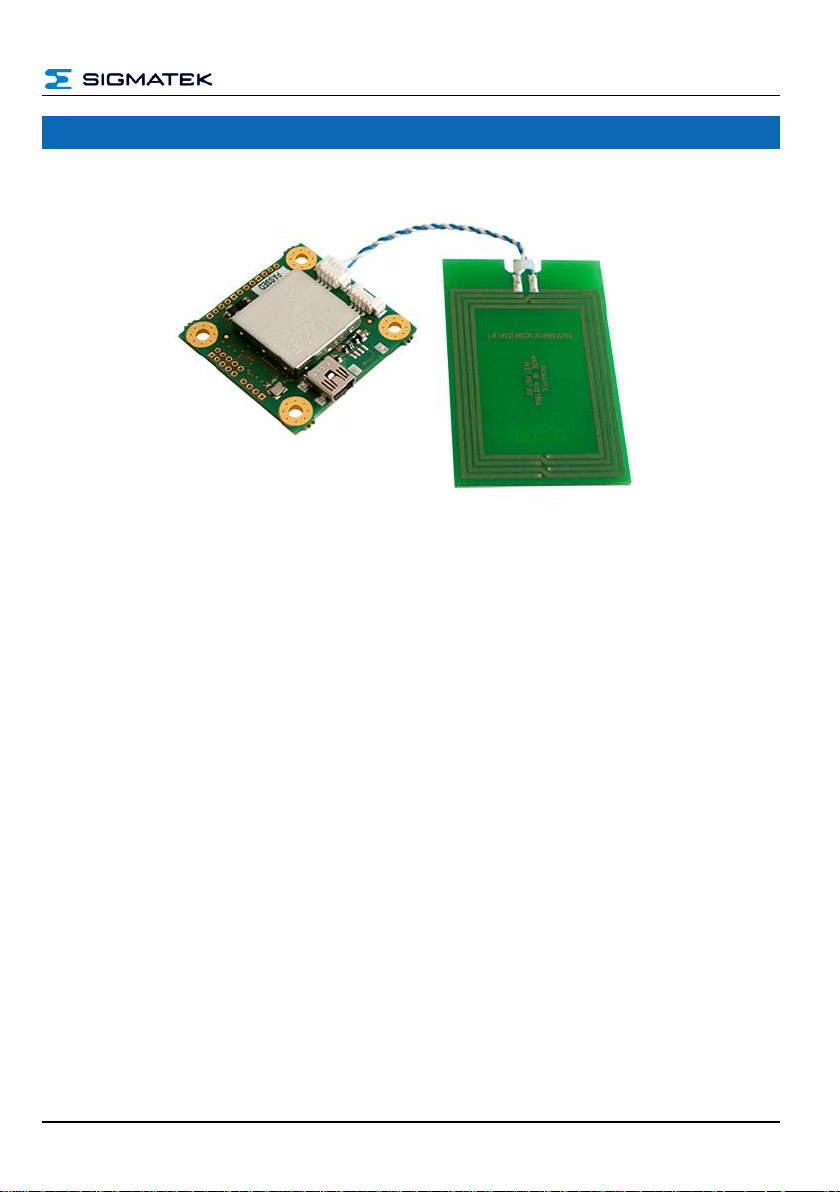
HF-RFID-READER
HF-RFID Reader
PRELIMINARY Page 1

HF-RFID-READER
Contents
1 Technical Data ......................................................................... 7
1.1 RFID Specification ........................................................................ 7
1.2 Electrical Requirements ............................................................... 7
1.3 Environmental Conditions ........................................................... 7
2 Mechanical Dimensions .......................................................... 9
3 Connector Layout .................................................................. 10
3.1.1 Applicable Connectors ...................................................................... 11
4 Protocol Description ............................................................. 12
4.1 Structure Packet ......................................................................... 12
4.2 Example of Communication ...................................................... 13
4.2.1 From Host to RFID Reader ............................................................... 13
4.2.2 From RFID Reader to Host ............................................................... 13
4.3 Breakdown of the Status Bytes ................................................. 13
4.4 Card Types for Protocol Handling ............................................ 14
4.4.1 Protocol ............................................................................................. 14
4.4.2 Card type .......................................................................................... 14
4.5 Checksum .................................................................................... 15
4.5.1 Data Configuration Example ............................................................. 15
5 Overview of the Available Commands ................................ 16
5.1 General Reader Commands ....................................................... 16
5.2 General Transponder Commands ............................................. 16
5.3 Tag-specific Commands ............................................................ 16
Page 2 PRELIMINARY

HF-RFID-READER
5.4 DESFire-Commands ................................................................... 17
6 Detailed Description of the Commands .............................. 18
6.1 Get-Reader Name – 0x00 ............................................................ 18
6.1.1 From Host to RFID Reader ............................................................... 18
6.1.2 From RFID Reader to Host ............................................................... 18
6.1.3 Example ............................................................................................ 18
6.2 Get-Product Name – 0x01 .......................................................... 19
6.2.1 From Host to RFID Reader ............................................................... 19
6.2.2 From RFID Reader to Host ............................................................... 19
6.2.3 Example ............................................................................................ 19
6.3 Get-Software Revision – 0x02 ................................................... 20
6.3.1 From Host to RFID Reader ............................................................... 20
6.3.2 From RFID Reader to Host ............................................................... 20
6.3.3 Example ............................................................................................ 20
6.4 Get-Hardware Revision – 0x03 .................................................. 21
6.4.1 From Host to RFID Reader ............................................................... 21
6.4.2 From RFID Reader to Host ............................................................... 21
6.4.3 Example ............................................................................................ 21
6.5 Get-Bootloader Revision – 0x04 ................................................ 22
6.5.1 From Host to RFID Reader ............................................................... 22
6.5.2 From RFID Reader to Host ............................................................... 22
6.5.3 Example ............................................................................................ 22
6.6 Calibrate Antenna – 0x05 ........................................................... 23
6.6.1 From Host to RFID Reader ............................................................... 23
6.6.2 From RFID Reader to Host ............................................................... 23
6.6.3 Example ............................................................................................ 23
6.7 Scan Tags – 0x06 ........................................................................ 24
PRELIMINARY Page 3

HF-RFID-READER
6.7.1 From Host to RFID Reader ............................................................... 24
6.7.2 From RFID Reader to Host ............................................................... 24
7 Configuration of Card Data................................................... 24
7.1 Example for 1 Card ..................................................................... 25
7.2 Example for 2 Cards ................................................................... 25
7.3 Select Tag – 0x07 ........................................................................ 27
7.3.1 From Host to RFID Reader ............................................................... 27
7.3.2 From RFID Reader to Host ............................................................... 27
7.3.3 Example ............................................................................................ 28
7.4 DeSelect Tag – 0x08 ................................................................... 29
7.4.1 From Host to RFID Reader ............................................................... 29
7.4.2 From RFID Reader to Host ............................................................... 29
7.5 Read-From Tag – 0x09 ............................................................... 30
7.5.1 Description of Non-encrypted Cards ................................................. 30
7.5.2 From Host to RFID Reader ............................................................... 30
7.5.3 From RFID Reader to Host ............................................................... 30
7.5.4 Example of Reading Non-encrypted Cards: ...................................... 31
7.6 Description of Encrypted Cards ................................................ 32
7.6.1 From Host to RFID Reader ............................................................... 32
7.6.2 From RFID Reader to Host ............................................................... 32
7.6.3 Examples of Reading Encrypted Cards: ........................................... 33
7.7 Write-To Tag – 0x0A ................................................................... 35
7.7.1 Description of Non-encrypted Cards ................................................. 35
7.7.2 From Host to RFID Reader ............................................................... 35
7.7.3 From RFID Reader to Host ............................................................... 35
7.7.4 Example of Writing to Non-encrypted Cards: .................................... 36
7.8 Description of Encrypted Cards ................................................ 37
Page 4 PRELIMINARY

HF-RFID-READER
7.8.1 From Host to RFID Reader ............................................................... 37
7.8.2 From RFID Reader to Host ............................................................... 37
7.8.3 Examples of Reading Encrypted Cards: ........................................... 38
7.9 Option Tag Commands – 0x0B .................................................. 39
7.9.1 Commands........................................................................................ 39
7.9.2 From Host to RFID Reader ............................................................... 39
7.9.3 From RFID Reader to Host ............................................................... 40
7.9.4 Example Read AFI – 0x00 ................................................................ 40
7.9.5 Example Write AFI – 0x01 ................................................................ 41
7.9.6 Example LOCK AFI – 0x02 ............................................................... 42
7.9.7 Example READ DSFID – 0x03.......................................................... 42
7.9.8 Example WRITE DSFID – 0x04 ........................................................ 43
7.9.9 Example LOCK DSFID – 0x05 .......................................................... 43
7.9.10 LOCK BLOCK – 0x06 ....................................................................... 44
7.9.11 SYS-INFO – 0x0A ............................................................................. 45
7.10 Get-ATS – 0x0C ........................................................................... 46
7.10.1 From Host to RFID Reader ............................................................... 46
7.10.2 From RFID Reader to Host ............................................................... 46
7.10.3 Example ............................................................................................ 46
7.11 SET-PPS – 0x0D .......................................................................... 47
7.11.1 From Host to RFID Reader ............................................................... 47
7.11.2 From RFID Reader to Host ............................................................... 47
7.11.3 Example ............................................................................................ 47
7.12 Execute Command – 0x0E ......................................................... 48
7.12.1 From Host to RFID Reader ............................................................... 48
7.12.2 From RFID Reader to Host ............................................................... 48
7.12.3 Example ............................................................................................ 49
7.13 SET RSSI – 0x11.......................................................................... 50
7.13.1 From Host to RFID Reader ............................................................... 50
PRELIMINARY Page 5

HF-RFID-READER
7.13.2 From RFID Reader to Host ............................................................... 50
7.13.3 Example ............................................................................................ 50
8 Communication Process Diagram ....................................... 51
8.1 Connecting with the Reader ...................................................... 51
8.2 With Tag Communication .......................................................... 52
9 Enumerators C ....................................................................... 53
10 Declaration of Conformity .................................................... 55
10.1 FCC Statement ............................................................................ 55
Documentation Changes .............................................................. 56
Page 6 PRELIMINARY
HF-RFID-READER
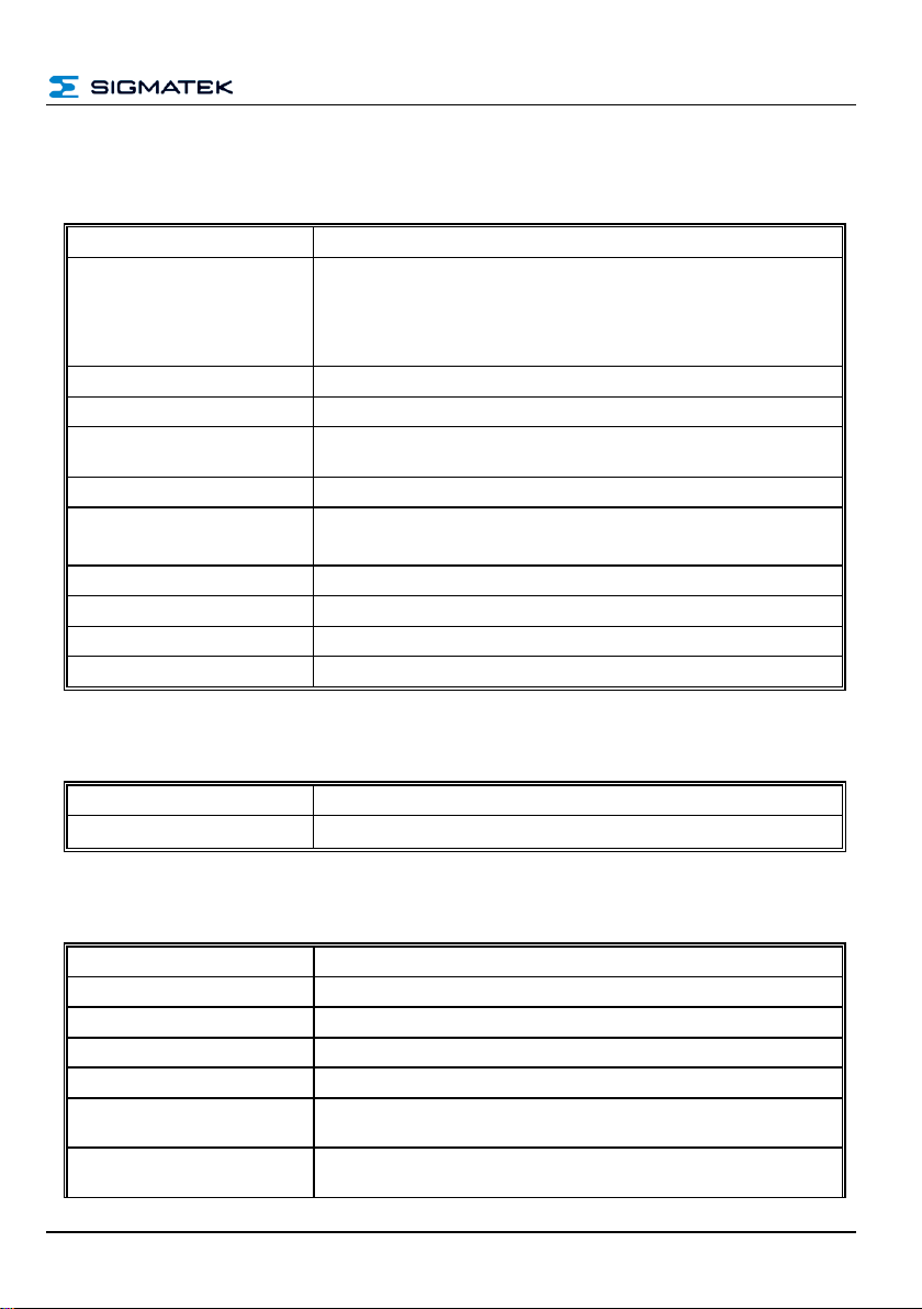
Protocol
ISO15693 ISO14443A ISO14443B B3
Supported cards
Mifare Ultralight / Ultralight C
Mifare Classic Mini / 1K / 4K
Mifare Desfire EV1 2K, 4K 8K
Mifare Pro, Plus
ISO15693 NXP ICOD SLI, TI TagIT, standard cards
RF power
100 mW
Operating frequency
13.56 MHz
Reading distance
up to 12 cm
(depending on the tag, antenna and ambient conditions)
Write distance
circa 70 % or the read distance
Host interface
USB CDC (Virtual Serial Port)
Default 57600 Baud
IO pins
3 software controllable GPIO pins
Antenna
external via Molex Pico Blade article No. 0532610471
Driver
Windows
Dimensions
41.00 mm x 37.70 mm x 6.50 mm (W x H x D)
Supply voltage
5 V DC ±5 % (via USB)
Current consumption
maximum 100 mA
Storage temperature
-20 ... +85 °C
Operating temperature
0 ... +55 °C
Humidity
0 - 95 %, non-condensing
EMV resistance
in accordance with EN 61000-6-2 (industrial area)
EMC - noise generation
in accordance with EN 61000-6-4 (industrial area)
Radio Communication Conformity
Europe
ETSI EN 302 291
Radio Communication Conformity
USA
FCC CFR 47 Part 15
1 Technical Data
1.1 RFID Specification
1.2 Electrical Requirements
1.3 Environmental Conditions
PRELIMINARY Page 7

HF-RFID-READER
Product safety
EN 60950-1:2006
Page 8 PRELIMINARY
HF-RFID-READER
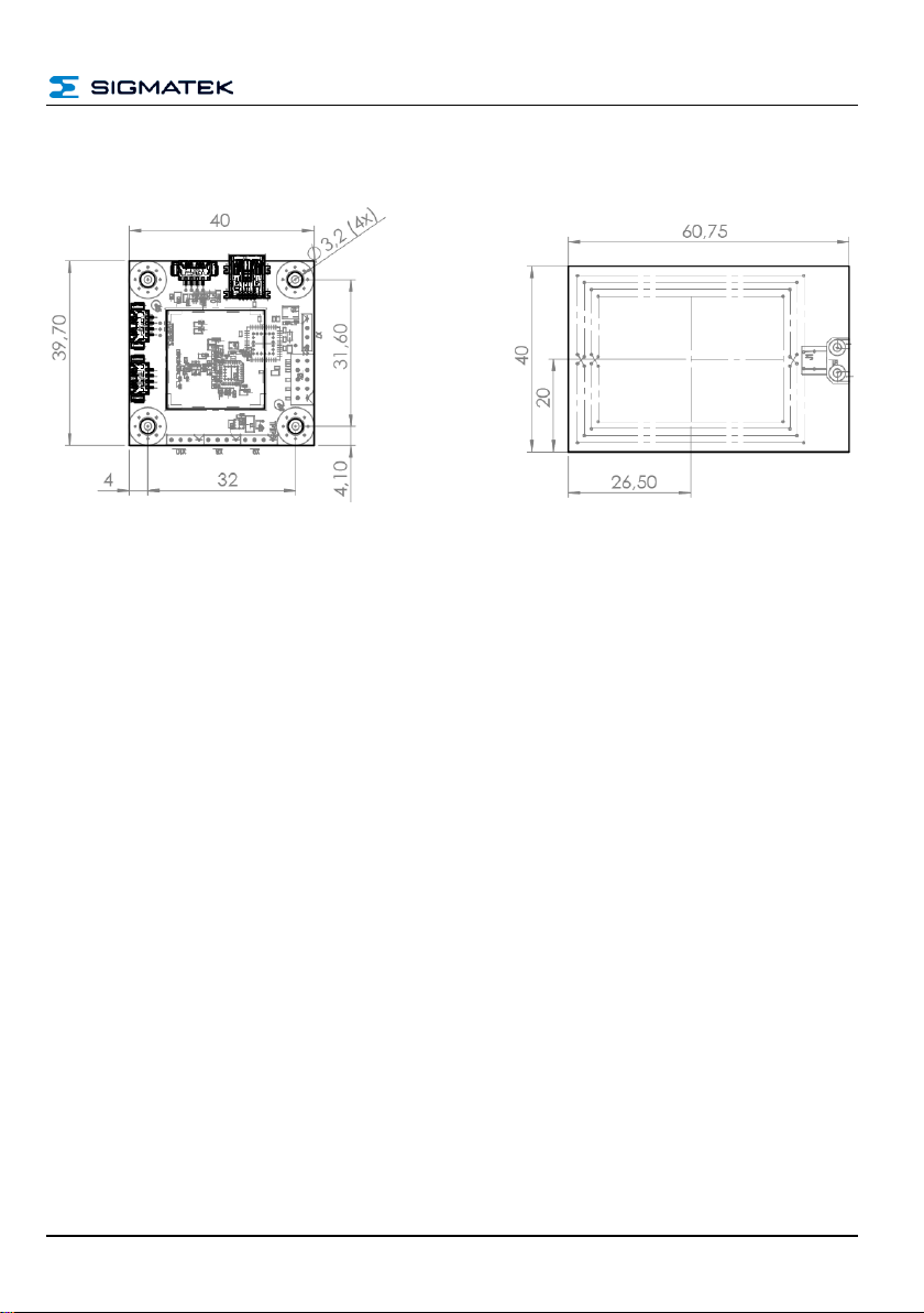
2 Mechanical Dimensions
PRELIMINARY Page 9
HF-RFID-READER
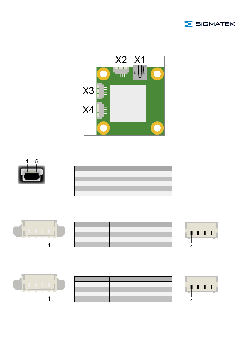
Pin
Function
1
+5 V
2
D- 3 D+
4
n.c. 5 GND
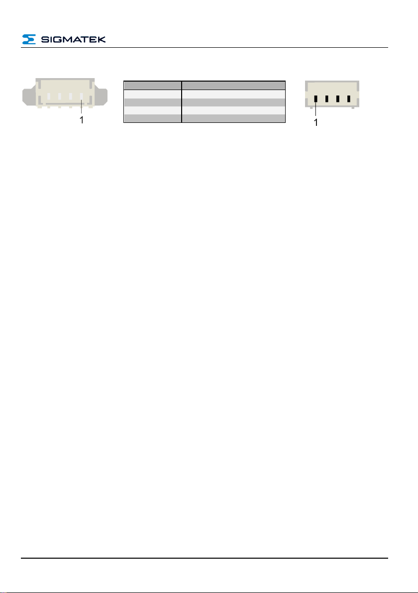
Pin
Function
1
GND
2
D+ 3 D- 4 +5 V
Pin
Function
1
+5 V
2
TXD 3 RXD
4
GND
3 Connector Layout
X1: USB-Device 2.0 (Type Mini-B)
X2: USB Device 2.0 (4-pin Molex Pico Blade)
X3: UART (4-pin Molex Pico Blade)
Page 10 PRELIMINARY
HF-RFID-READER
Pin
Function
1
RFO 2
2
GND 3 GND
4
RFO 1
X4: Antenna (4-pin Molex Pico Blade)
3.1.1 Applicable Connectors
X1: USB 2.0 (Type A) (not included in delivery)
X2: 4-pin Molex Pico Blade - 51021-0400
X3: 4-pin Molex Pico Blade - 51021-0400
X4: 4-pin Molex Pico Blade - 51021-0400
PRELIMINARY Page 11
HF-RFID-READER
Description
Number
Short description
Color
Instruction
1 byte
CMD
Blue
status
1 byte
STC
red
Data length
2 bytes
DLI
Orange
DATA
variable
Data
green
Checksum
1 byte
CS
Black
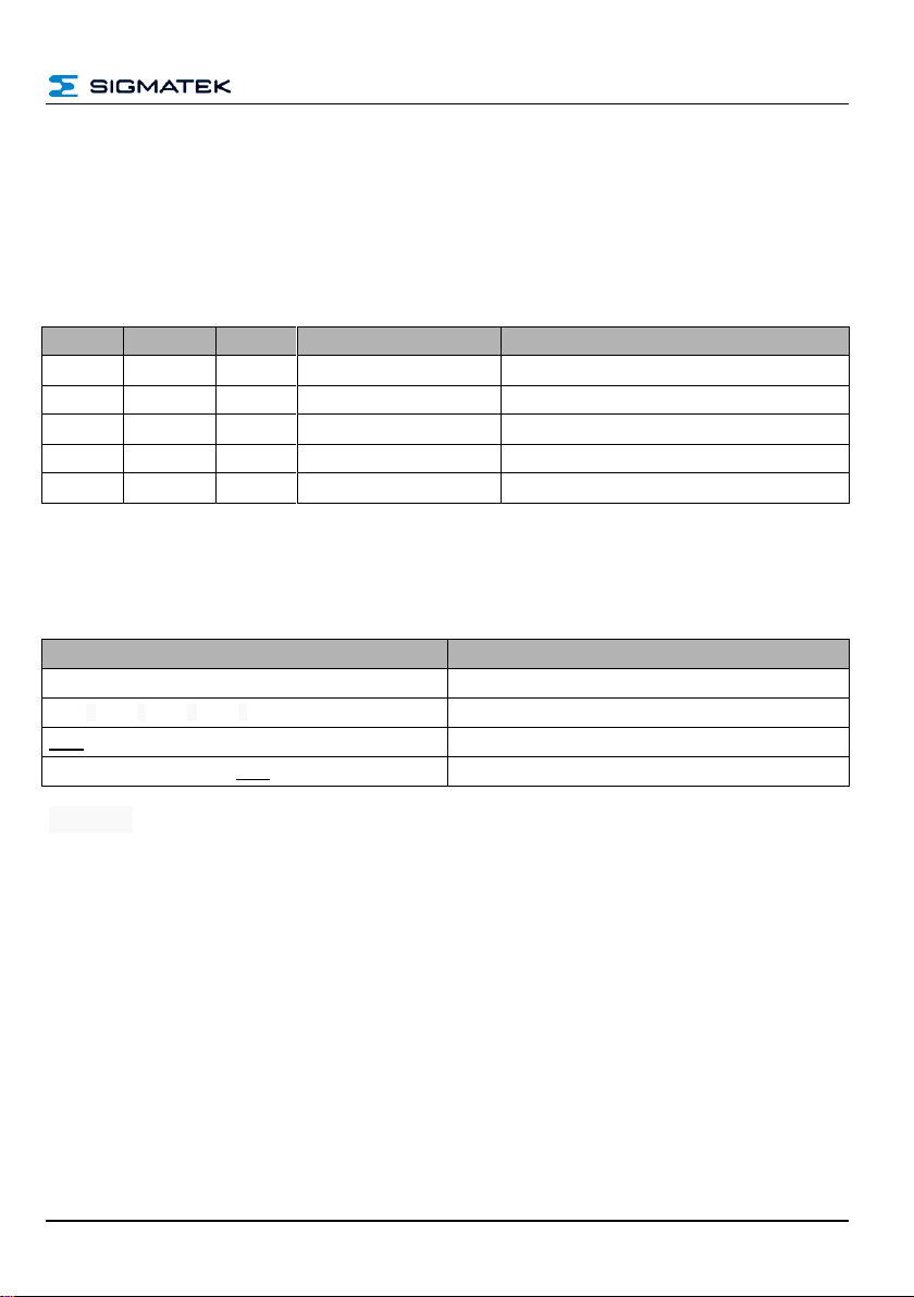
4 Protocol Description
The protocol is always the same and independent of the interface used.
4.1 Structure Packet
All packets between the reader and host have the same structure and must be interpreted
the same.
Instruction The field command describes which command should be run. This is described
in chapter 5.
Status: This byte is always 0x00 for commands from the host to the RFIE reader. The
status is used exclusively as a return value for the reader and indexes the status of the
currently executed commands.
Data Length: The "Data length" indicates how much payload data is transferred after this
byte.
Data: The payload data to evaluate.
Checksum: The checksum is used to verify the transferred data. More information can be
found in chapter 4.4.
Page 12 PRELIMINARY
HF-RFID-READER
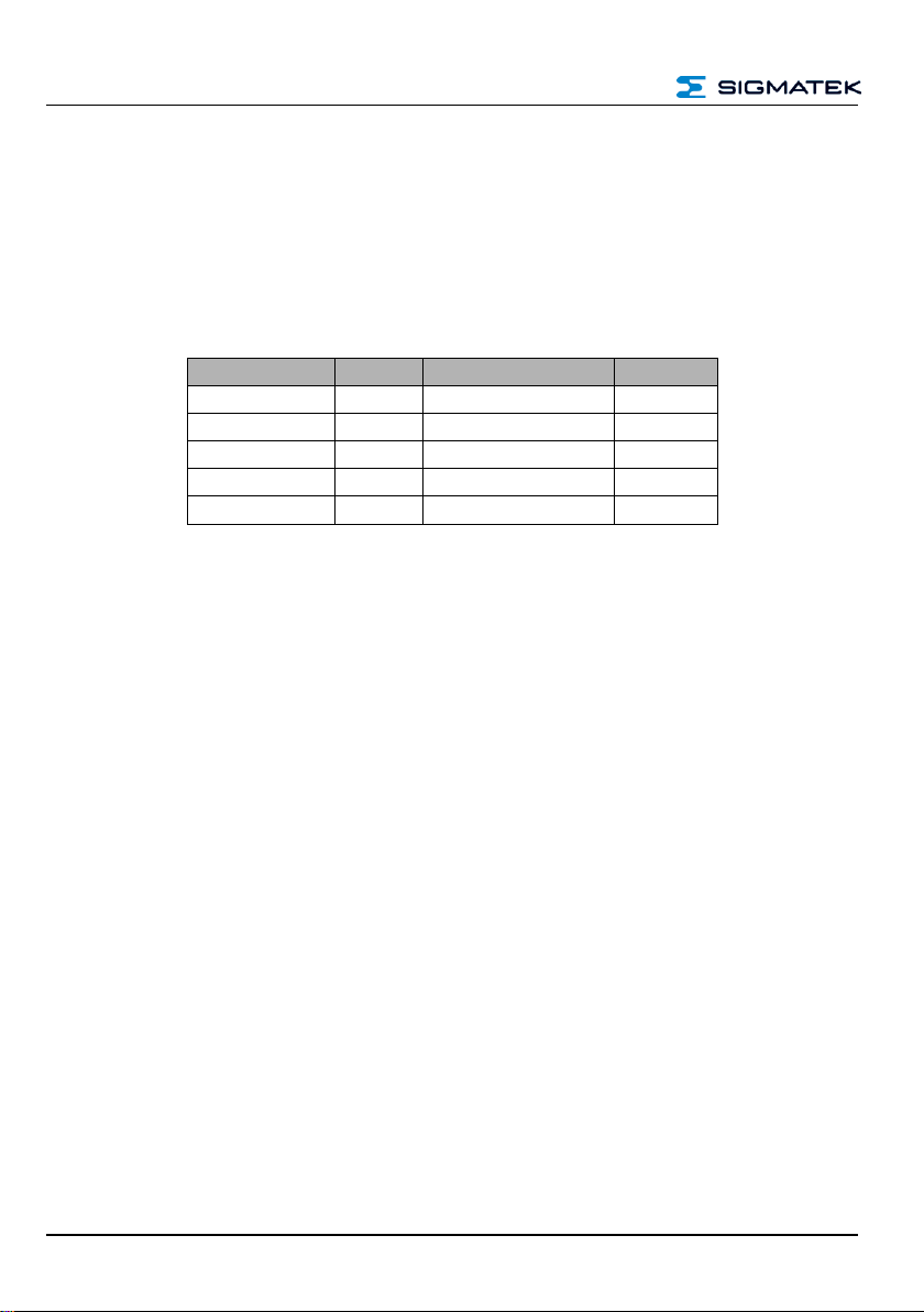
Byte
No.
Number
Contents
Data Sent
Value
Description
0
1 byte
CMD
0x02 Command 0x02 "Get Software Revision"
1
1 byte
STC
0x00 Status code for read always 0x00
2 – 3
2 bytes
DLI
0x00, 0x00
Data length
4
1 byte
CS
0x02 Data checksum
Byte
No.
Number
Contents
Data Sent
Description
0
1 byte
CMD
0x02
Command 0x02 "Get Software Revision"
1
1 byte
STC
0x00
status code from the host to the reader
2 – 3
2 bytes
DLI
0x00, 0x00
Data length
4 – 7
4 bytes
Data
0x00, 0x01, 0x00, 0x06
Software Revision 01.06
8
1 byte
CS
0x3D
Checksum
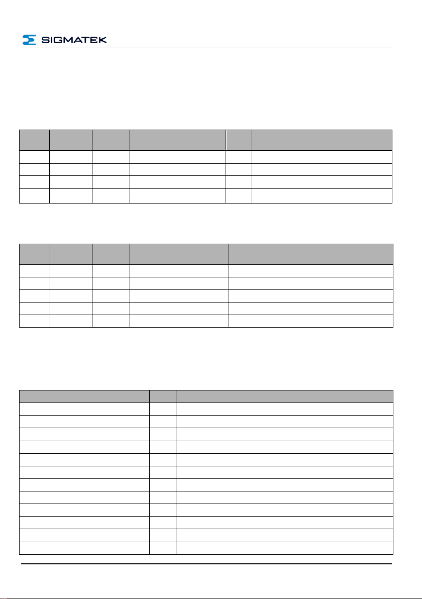
Name
Value
Description
ERR_RET_SUCCESS
0x00
The command was successfully executed
ERR_ET_PARM
0x01
The wrong parameter was sent
ERR_RET_DATA_PUSH
0x02
The wrong data were sent
ERR_RET_CMD_INVALID
0x03
The command used does not exist
ERR_RET_CRC_ERR
0x04
The Checksum is defective
ERR_RET_LENGTH
0x05
The wrong data length was entered
ERR_RET_CMD_DATA
0x06
The data length and transmitted data do not match
ERR_RET_CALIBRATE_ANT
0x0F
The antenna could not be calibrated
ERR_RET_TIMEOUT
0x10
A time out event has occurred
ERR_RET_FIFO_DATA
0x11
No data in FIFO
ERR_RET_COLLISION
0x12
Card collision
ERR_RET_EXEC_CMD
0x13
Error while executing a command
4.2 Example of Communication
As an example, the command 0x02 – Get Software-Revision is used here.
4.2.1 From Host to RFID Reader
4.2.2 From RFID Reader to Host
4.3 Breakdown of the Status Bytes
Here, the status bytes and there meanings are explained.
PRELIMINARY Page 13
HF-RFID-READER
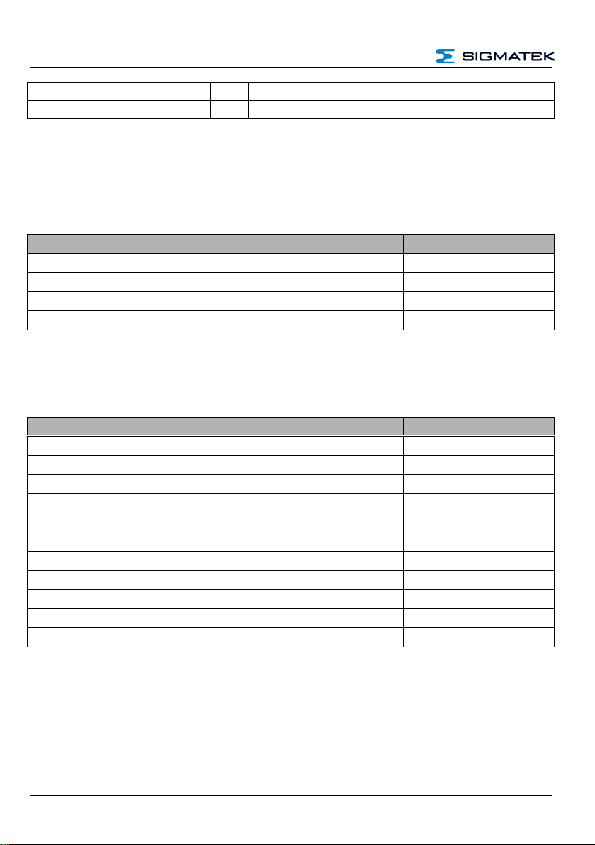
ERR_RET_CARD_NOT_SUPPORTED
0x14
The RFID card is not supported
ERR_RET_AUTH
0x15
Login with card failed
Norm
Value
Example
Version
ISO14443A
0x00
Mifare Classic 1K
ISO14443B
0x01
NFC Label such as SRI512
ISO15693
0x02
NXP ICode SLI
Unknown card
0xFF
unidentified card
Card type
Value
Example
Version
Mifare Ultralight
0x00
NXP MF0ICU1
Mifare Mini
0x01
NXP MF1ICS20
Mifare Classic 1K
0x02
NXP MF1S503
Mifare Classic 4K
0x03
NXP MF1S70
Mifare Plus
0x04
MF1 S PLUS60
Mifare DESFire
0x05
MF3 IC D41
Mifare ISO14443A-4
0x06
ISO14443B Srix
0x07
ISO14443B Srix 176
0x08
ISO15693 (default)
0x09
NXP ICode SLI, TI TagIT
Unknown card
0xFF
unidentified card
4.4 Card Types for Protocol Handling
4.4.1 Protocol
See Enumerators Table, Chapter 4.6
4.4.2 Card type
See Enumerators Table, Chapter 4.6
Page 14 PRELIMINARY
HF-RFID-READER
Byte No.
Number
Contents
Data Sent
Description
0
1 byte
CMD
0x06
Command "Scan Tags"
1
1 byte
STC
0x00
Status code for read always 0x00
2 – 3
2 bytes
DLI
0x01, 0x00
Data length
4
1 byte
Data
0x00
Card type
5
1 byte
CS
0x07
Data checksum
Bytes
Number
0x06 0x00 0x01 0x00 0x02
data to send (command, status...)
0x06 ⊻ 0x00 ⊻ 0x01 ⊻ 0x00 ⊻ 0x02
XOR calculation
0x05
Checksum
0x06 0x00 0x01 0x00 0x02 0x05
data to send including the checksum
4.5 Checksum
The checksum is an XOR from all bytes. This is calculated as follows:
Example command "Scan Tags – 0x06"
4.5.1 Data Configuration Example
Below the data (0x06 0x00 0x01 0x00 0x02) that should be sent to the reader can be seen.
Before the data are sent, the checksum (byte 5) must be formed.
The checksum in an XOR or each subsequent byte.
⊻ = XOR
PRELIMINARY Page 15
HF-RFID-READER
Instruction
Value
Description
Version
GET-Reader Name
0x00
Calls the reader name
GET-Product Name
0x01
Calls the product name
GET-Software Rev.
0x02
Calls the software version
GET-Hardware Rev.
0x03
Calls the hardware version
GET-Bootloader Rev.
0x04
Calls the booloader version
Calibrate_Antenna
0x05
Calibrates the antenna
GET-Feature
0x10
Calls the available functions
SET-RSSI
0x11
Activates the RSSI value transition
GPIO_Commands
0x0F
Enables the control of GPIOs
Instruction
Value
Description
Version
Scan_Tags
0x06
Searches for tags that are in range.
Select_Tag
0x07
Selects a tag
Deslect_Tag
0x08
Deselects a tag
Read_From_Tag
0x09
Reads data from a tag
Write_To_Tag
0x0A
Writes data to a tag
Instruction
Value
Description
Version
Option_Tag
0x0B
See chapter 7.9 (ISO15693 only)
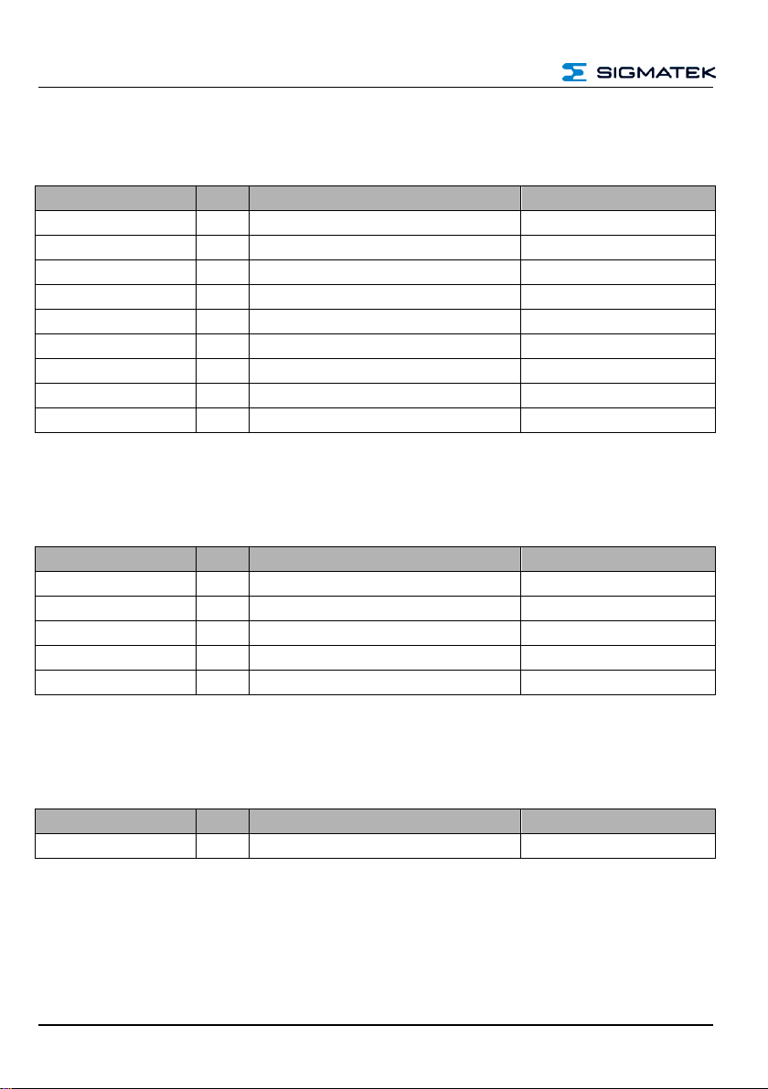
5 Overview of the Available Commands
5.1 General Reader Commands
5.2 General Transponder Commands
General commands that can be used in all tags.
5.3 Tag-specific Commands
The tag-specific commands are limited to a tag group or type.
Page 16 PRELIMINARY
 Loading...