


ETT 412
Touch Operating Panel
Technical Manual
Date of creation: 07.02.2019
Version date: 12.03.2019
Article number: 01-230-412-E

Publisher: SIGMATEK GmbH & Co KG
A-5112 Lamprechtshausen
Tel.: +43/6274/4321
Fax: +43/6274/4321-18
Email: office@sigmatek.at
WWW.SIGMATEK-AUTOMATION.COM
Copyright © 2019
SIGMATEK GmbH & Co KG
Translation from German
All rights reserved. No part of this work may be reproduced, edited using an electronic system, duplicated or distributed in any form (print, photocopy, microfilm or in any other process) without express permission.
We reserve the right to make changes in the content without notice. SIGMATEK GmbH & Co KG is not responsible for
technical or printing errors in this handbook and assumes no responsibility for damages that occur through its use.
BUILD-IN TOUCH TERMINAL ETT 412
12.03.2019 Page 1
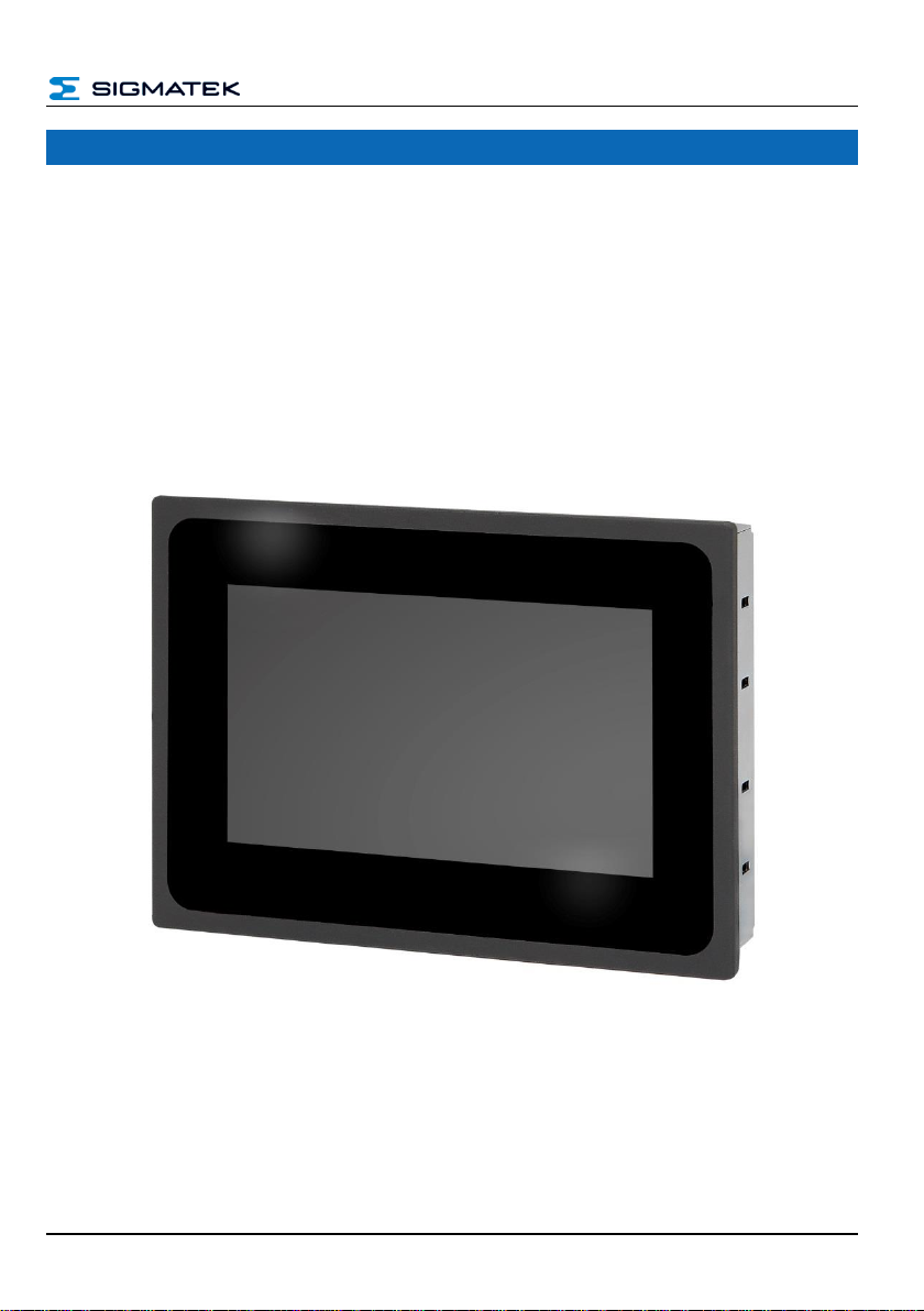
Touch Operating Panel ETT 412
The ETT 412 is used to visualize automated processes. Process diagnostics as well as operating and monitoring automated procedures are simplified using this control.
A projected capacitive touch screen serves as the input medium for process data and parameters. The output is shown on a 4.3" TFT color display.
With a LASAL visualization tool, graphics can be created on the PC, then stored and displayed on the terminal. Data is exchanged with the CPU via the CAN bus.
The display is constructed with a black anodized aluminum front.

ETT 412 BUILD-IN TOUCH TERMINAL
Page 2 12.03.2019
Contents
1 Introduction ............................................................................. 4
1.1 Target Group/Purpose of this Manual ........................................ 4
1.2 Important Reference Documentation ......................................... 4
1.3 Contents of Delivery ..................................................................... 4
2 Basic Safety Guidelines ......................................................... 5
2.1 Symbols Used ............................................................................... 5
2.2 Disclaimer ...................................................................................... 6
2.3 General Safety Guidelines ........................................................... 7
2.5 Guidelines...................................................................................... 8
2.5.1 EU Conformity Declaration .................................................................. 8
3 Technical Data ........................................................................ 9
3.1 Performance Data ......................................................................... 9
3.2 Electrical Requirements ............................................................... 9
3.3 Controller ....................................................................................... 9
3.4 Display ........................................................................................... 9
3.5 Environmental Conditions ......................................................... 10
3.6 Miscellaneous ............................................................................. 10
4 Mechanical Dimensions ........................................................11
5 Connector Layout ..................................................................12
5.1 X1: CAN Bus (5-pin Phoenix RM 3.5) ........................................ 12
5.2 X2: Supply (4-pin Phoenix RM 3.5) ........................................... 12

BUILD-IN TOUCH TERMINAL ETT 412
12.03.2019 Page 3
5.3 Protective Earth Connection ..................................................... 13
5.4 Applicable Connectors ............................................................... 14
6 Mounting Instructions ........................................................... 15
6.1 Vertical Mounting Position ........................................................ 15
7 CAN Bus Protocol ................................................................. 16
8 CAN Bus Setup ...................................................................... 16
8.1 CAN Bus Station Number .......................................................... 16
8.2 CAN Bus Data Transfer Rate ..................................................... 16
9 CAN Bus Termination ........................................................... 17
10 Cleaning the Touch Screen .................................................. 18
11 Transport/Storage ................................................................. 19
12 Assembly/Installation ........................................................... 20
12.1 Check List .................................................................................... 20
12.1.1 Check Contents of Delivery............................................................... 20
12.2 Maintenance ................................................................................ 20
12.3 Repair ........................................................................................... 20
13 Disposal ................................................................................. 21

ETT 412 BUILD-IN TOUCH TERMINAL
Page 4 12.03.2019
1 Introduction
1.1 Target Group/Purpose of this Manual
This manual contains all information required for operating the ETT 412.
This manual is intended for:
• Project planners
• Technicians
• Configurators/commissioning engineers
• Machine operators
• Maintenance/test technicians
General knowledge of automation technology is required.
Further help and training information, as well as the appropriate accessories can be found on
our website www.sigmatek-automation.com
Our support team is also happily available to answer your questions.
Information on our support hotline, as well as business hours can be found on the website
mentioned above.
1.2 Important Reference Documentation
• HW IP Address Setting documentation
This document can be downloaded from our website.
1.3 Contents of Delivery
1x ETT 412
1x opposing connector
Additional documents may be included with delivery.
BUILD-IN TOUCH TERMINAL ETT 412
12.03.2019 Page 5
2 Basic Safety Guidelines
2.1 Symbols Used
The following symbols are used in the operator documentation for warning and danger messages, as well as informational notes:
DANGER
Identifies an immediate danger with high risk, which will lead to immediate
death or serious injury if not avoided.
Identifie un danger immédiat avec un risque élevé, entraînant le décès immédiat ou des blessures graves s’il n’est pas évité..
WARNING
Identifies a possible danger with a mid-level risk, which can lead to death or
(serious) injury if not avoided.
Indique un danger possible d’un risque moyen de décès ou de (graves)
blessures si les consignes de sécurité ne sont pas respectées
CAUTION
dentifies a low risk danger, which can lead to injury or property damage if not
avoided.
Indique un danger avec un niveau de risque faible des blessures légères ou
des dommages matériels si les consignes de sécurité ne sont pas respectées.
Provides user tips, informs of special features and identifies especially important information in the text.
Fournit des conseils d’utilisation, informe sur les fonctions particulaires et
souligne les informations particulièrement importantes dans le texte.

ETT 412 BUILD-IN TOUCH TERMINAL
Page 6 12.03.2019
2.2 Disclaimer
The contents of this document were prepared with the greatest care. However, deviations cannot be ruled out. This document is regularly checked and
required corrections are included in the subsequent versions. The machine
manufacturer is responsible for the proper assembly, as well as device configuration. The machine operator is responsible for safe handling, as well as
proper operation.
The current document can be found on our website. If necessary, contact our
support.
Subject to technical changes, which improve the performance of the devices.
The following documentation is purely a product description. It does not serve
to guarantee properties under the warranty.
Please thoroughly read the corresponding data sheets, operating instructions
and this system handbook before handling a product.
SIGMATEK GmbH & Co KG is not liable for damages caused through,
non-compliance with these instructions or applicable regulations.
The general and special safety instructions described in the following sections, as well as technical regulations, must therefore be observed.

BUILD-IN TOUCH TERMINAL ETT 412
12.03.2019 Page 7
2.3 General Safety Guidelines
Observe all on-site rules and regulations for accident prevention and occupational safety.
According to EU guidelines, the operating instructions are a component of a
product.
This manual must therefore be accessible in the vicinity of the machine since
it contains important instructions.
This technical documentation should be included in the sale, rental or transfer
of the product.
Maintain this manual in readable condition and keep it accessible for reference.
Operate the unit with devices and accessories approved by SIGMATEK only.
CAUTION
In addition, the Safety Guidelines in the other sections of these instructions
must be observed. These instructions are visually emphasized by symbols.
The module complies with EN 61131-2.
In combination with a machine, the machine builder must comply with EN
60204-1 standards.
For your own safety and that of others, compliance with the environmental
conditions is essential.
To perform maintenance or repairs, disconnect the system from the power
supply.
En outre, les consignes de sécurité mentionnées dans d’autres sections de
ce manuel doivent être respectées. Ces directives sont indiquées avec les
symboles graphiques.
Le module est conforme à la norme EN 61131-2.
En combinaison avec une machine, le constructeur de la machine doit re-
specter la norme EN 60204-1.
L’armoire de commande doit être raccordée correctement à la terre.
Pour l'entretien et les réparations, débranchez le système de l'alimentation.

ETT 412 BUILD-IN TOUCH TERMINAL
Page 8 12.03.2019
2.5 Guidelines
The panel was constructed in compliance with European Union guidelines.
2.5.1 EU Conformity Declaration
CE Declaration of Conformity
The ETT 412 conforms to the following European guidelines:
• 2014/35/EU Low-voltage guideline
• 2014/30/EU “Electromagnetic Compatibility” (EMC guideline)
• 2011/65/EU “Restricted use of certain hazardous substances in
electrical and electronic equipment” (RoHS Guideline)
BUILD-IN TOUCH TERMINAL ETT 412
12.03.2019 Page 9
3 Technical Data
3.1 Performance Data
Interfaces
1x CAN bus
Data rate max. 1 Mbit/s
3.2 Electrical Requirements
Supply voltage
typically +24 V (+18-30 V DC)
Current consumption at +24 V DC
typically 75 mA
maximum 130 mA
Inrush current
typically 0.8 A for 10 ms
maximum 1.2 A for 20 ms
3.3 Controller
Controller
Cortex-M3
Internal data memory for visualization (SDRAM)
8-Mbyte
Internal data memory for visualization (Flash)
8-Mbyte
3.4 Display
Type
4.3" TFT-LCD color display
Resolution
480 x 272
Pixel size
0.198 x 0.198 mm
Number of pixels
480*3 (RGB) x 272 pixels
Active surface
95.04 x 53.86 mm
Color depth
24-bit
Backlighting
10x LED, white, adjustable
Contrast
600:1
Touch
projective capacitive
Brightness
typically 400 cd/m²
Visible field
left, right 80, above 70° and below 60°

ETT 412 BUILD-IN TOUCH TERMINAL
Page 10 12.03.2019
3.5 Environmental Conditions
Storage temperature
-10 ... +70 °C
Environmental temperature
0 ... +55 °C
Humidity
10-90 %, non-condensing
Installation altitude above sea
level
0-2000 m without derating,
> 2000 m with derating of the maximum environment temperature by 0.5 °C
per 100 m
Operating conditions
pollution degree 2
indoor use
EMC resistance
in accordance with EN 61000-6-2:2007 (industrial area)
EMC noise generation
in accordance with EN 61000-6-4 (industrial area)
Vibration resistance
EN 60068-2-6
3.5 mm from 5-8.4 Hz
1 g from 8.4-150 Hz
Shock resistance
EN 60068-2-27
15 g
Protection type
EN 60529
front: IP65
cover: IP20
3.6 Miscellaneous
Article number
01-230-412
Hardware version
1.x
Standard
CE

BUILD-IN TOUCH TERMINAL ETT 412
12.03.2019 Page 11
4 Mechanical Dimensions
Operating unit dimensions
132 x 94 x 35.5 mm (W x H x D) with opposing connector
145.0 x 107.0 x 35.5 mm (W x H x D) with opposing connector and
mounting brackets
Control cabinet cutout
127 x 89 (W x H) (± 0.4 mm)
Material
front: 0.7 mm glass (touch screen) in black anodized 3 mm
aluminum frame
cover: 0.8 mm chromed sheet steel
Weight
300 g

ETT 412 BUILD-IN TOUCH TERMINAL
Page 12 12.03.2019
5 Connector Layout
5.1 X1: CAN Bus (5-pin Phoenix RM 3.5)
5.2 X2: Supply (4-pin Phoenix RM 3.5)
Pin
Signal
Function
1
CAN A
CAN LOW IN
2
CAN B
CAN HIGH IN
3
CAN A
CAN LOW OUT
4
CAN B
CAN HIGH OUT
5
GND
GND
Pin
Signal
Function
1
+24 V
Supply voltage
2
+24 V
Supply voltage
3
GND
GND
4
GND
GND
BUILD-IN TOUCH TERMINAL ETT 412
12.03.2019 Page 13
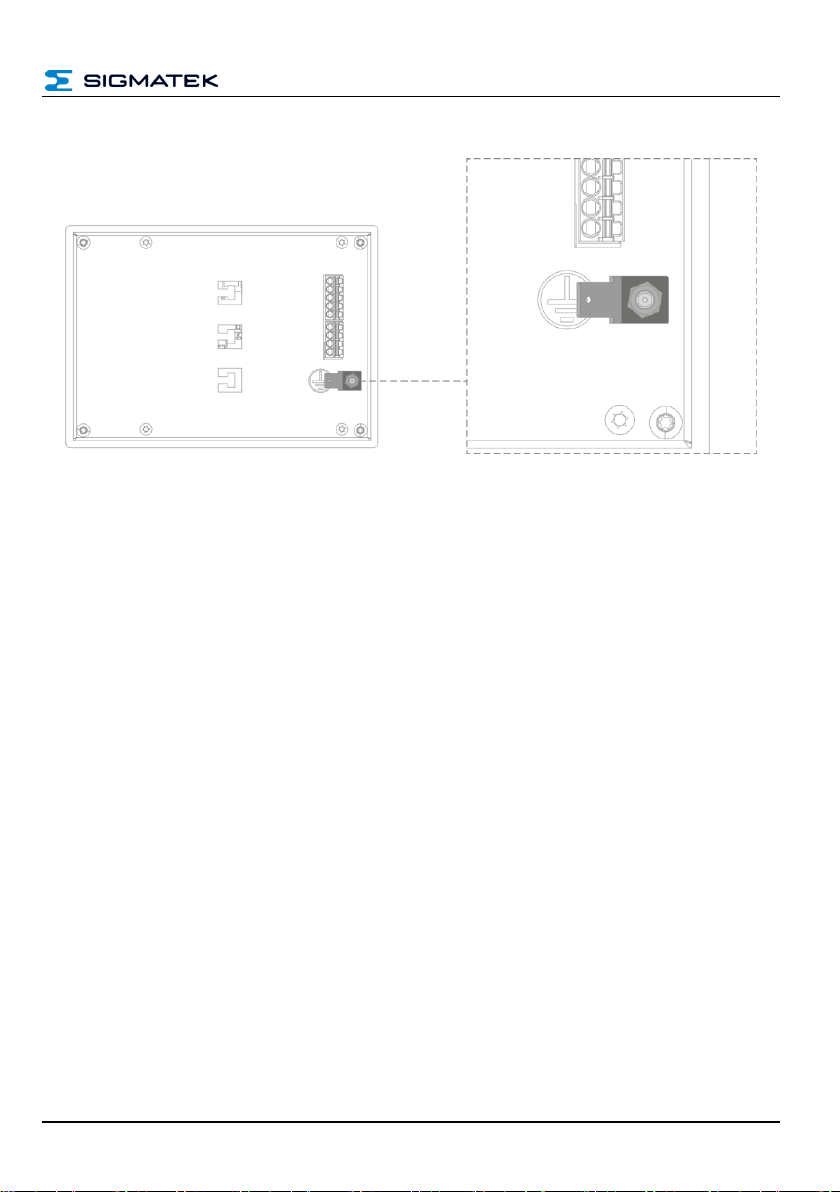
5.3 Protective Earth Connection
The terminal must be grounded to protective earth via the M3 threaded bolts and the blade
terminal, as well as to the control cabinet over a broad surface via the mount. It is important
to establish a low-Ohm connection to ground to ensure error-free function. The ground connection must be made with the maximum cross section and largest (electrical) surface possible. The cable length of the ground connection must also be kept as short as possible.
ETT 412 BUILD-IN TOUCH TERMINAL
Page 14 12.03.2019
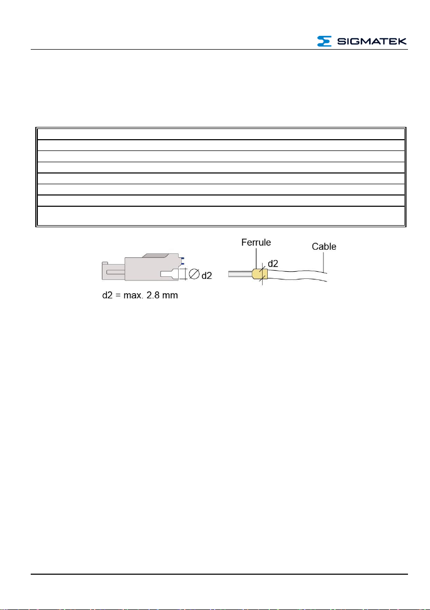
5.4 Applicable Connectors
Connectors:
X1, X2: Connectors with spring terminals (included in delivery)
Connections
Stripping length/sleeve length:
10 mm
Mating direction:
parallel to the conductor axis or circuit board
Conductor cross section rigid:
0.2-1.5 mm2
Conductor cross section flexible:
0.2-1.5 mm2
conductor cross section strands ultrasonically compacted:
0.2-1.5 mm2
Conductor cross section AWG/kcmil:
24-16
Conductor cross section flexible with ferrule:
0.25-1.5 mm2
Conductor cross section flexible with ferrule and plastic sleeve:
0.25-0.75 mm2 (reason for reduction d2 of the
ferrule)
BUILD-IN TOUCH TERMINAL ETT 412
12.03.2019 Page 15
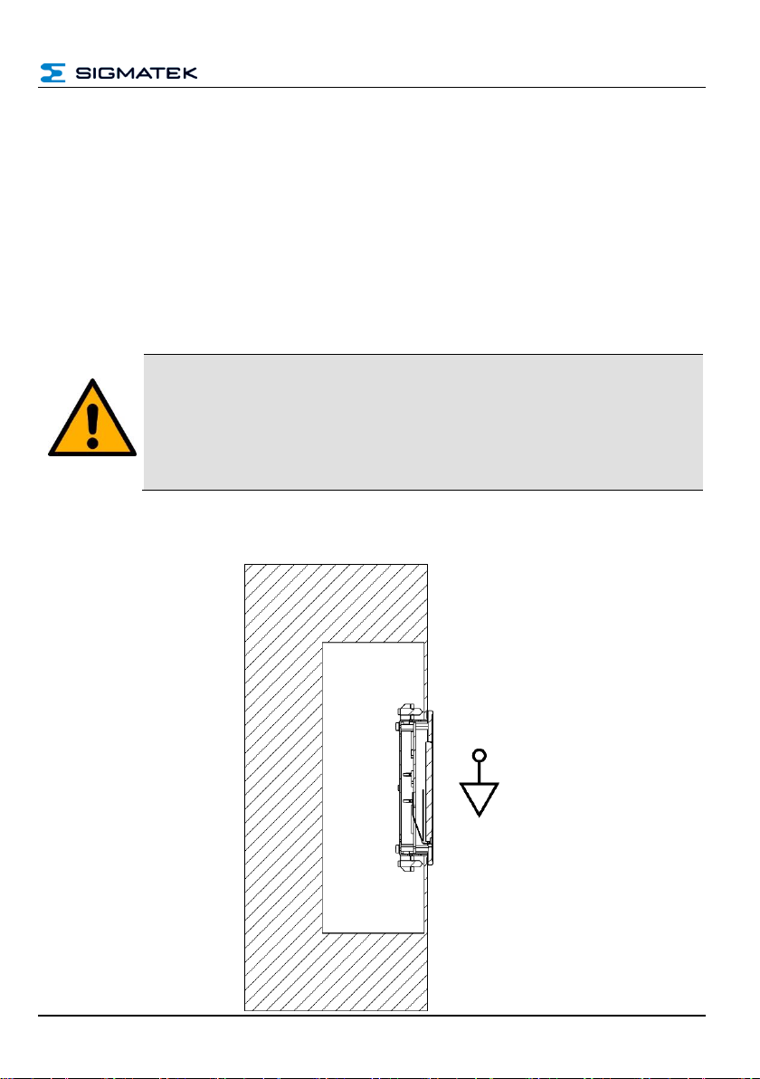
6 Mounting Instructions
The build-in terminal is provided for mounting in a control cabinet wall. For mounting in the
control cabinet wall, 8 angle clamps with threaded pins are provided. The front is therewith
pressed against the outer control cabinet wall. The brackets are affixed using a flat head
screwdriver with 0.2 Nm and therewith guarantee the necessary IP protection level for the
front.
The modules must be mounted vertically with enough clearance to nearby components
and/or the control cabinet back wall. This is necessary for optimal cooling and air circulation,
so that proper function up to the maximum operating temperature is ensured.
CAUTION
The terminal must be grounded to protective earth via the M3 threaded bolts
and the blade terminal, as well as to the control cabinet over a broad surface
via the mount.
La borne doit être reliée à la terre par l'intermédiaire des boulons filetés M3
et de la borne à lame, ainsi qu'à l'armoire électrique sur une large surface via
le support.
6.1 Vertical Mounting Position
ETT 412 BUILD-IN TOUCH TERMINAL
Page 16 12.03.2019
7 CAN Bus Protocol
Display communication CAN object number:
CAN bus object for receiving data: 0x020 + CAN bus station (0x00 – 0x1F)
CAN bus object for sending data: 0x040 + CAN bus station (0x00 – 0x1F)
8 CAN Bus Setup
This section explains how to configure a CAN bus correctly. The following parameters must
first be set: Station number and data transfer rate.
During start up the parameters can be set on the setup screen of the terminal.
8.1 CAN Bus Station Number
Each CAN bus station is assigned its own station number. With this station number, data can
be exchanged with other stations connected to the bus. Up to 31 stations can be installed in
a CAN bus system. In a CAN bus system however, each station number can only be assigned
once!
8.2 CAN Bus Data Transfer Rate
Various data transfer rates (baud rates) can be set on the CAN bus. The longer the bus line
is, the lower the data transfer rate that must be selected.
Value
Baud rate
maximum length
1
500 kbits/s
80 m
2
250 kbits/s
160 m
3
125 kbits/s
320 m
4
100 kbits/s
400 m
5
50 kbits/s
800 m
6
20 kbits/s
1200 m
7
1 Mbit/s
30 m
These values apply to the following cable: 120 , Twisted Pair.

BUILD-IN TOUCH TERMINAL ETT 412
12.03.2019 Page 17
9 CAN Bus Termination
In a CAN bus system, both end modules must be terminated. This is necessary to avoid
transmission errors caused by reflections in the line. For the CAN bus a shielded connector
cable must be used. The cable shielding must have a low-Ohm connection to the ground.
The line termination is provided by a 120 Ω resistor on the opposing con-
nector between PIN 3 and PIN 4.
ETT 412 BUILD-IN TOUCH TERMINAL
Page 18 12.03.2019
10 Cleaning the Touch Screen
WARNING
Before cleaning the touch screen, the HGW must be turned off in order to
prevent triggering functions or commands unintentionally!
Avant de nettoyer l'écran tactile, le HGW doit être éteint afin d'éviter tout déclenchement involontaire de fonctions ou de commandes!
The touch screen can only be cleaned with a soft, damp cloth. To dampen the cloth, a mild
cleaning solution such as antistatic foam cleaner is recommended. To avoid fluids/cleaning
solutions from getting into the housing, the device must not be sprayed directly. To clean, no
corrosive cleaning solutions, chemicals, abrasive cleansers or hard objects that can scratch
or damage the touch screen may be used. The use of steam jets or compressed air is
prohibited.
DANGER
If the device is contaminated with toxic or corrosive chemicals, it must be
carefully cleaned as quickly as possible to prevent personal injury and machine damage!
i l'appareil est contaminé par des produits chimiques toxiques ou corrosifs, il
doit être nettoyé avec soin le plus rapidement possible afin d'éviter des dommages corporels et matériels!
To ensure the optimal function of the panel, the touch screen should be
cleaned in regular intervals!
To avoid damaging the touch screen, using either the fingers or a stylus to
operate the panel is recommended.

BUILD-IN TOUCH TERMINAL ETT 412
12.03.2019 Page 19
11 Transport/Storage
This device contains sensitive electronics. During transport and storage, high
mechanical stress must therefore be avoided.
For storage and transport, the same values for humidity and vibration as for
operation must be maintained!
CAUTION
TTemperature and humidity fluctuations may occur during transport. Ensure
that no moisture condenses in or on the device.
Pendant le transport, des fluctuations de température et d'humidité peuvent
survenir. Veillez à ce qu'il n'y ait pas de condensation d'humidité dans ou sur
l'appareil.

ETT 412 BUILD-IN TOUCH TERMINAL
Page 20 12.03.2019
12 Assembly/Installation
12.1 Check List
12.1.1 Check Contents of Delivery
Ensure that the contents of the delivery are complete and intact. See chapter 1.3 Contents
of Delivery for more information.
WARNING
Do not use damaged components. These could disrupt or damage your system.
If damaged components are found in the delivery, please contact our customer service.
N'utilisez pas de composants endommagés. Cela pourrait perturber ou endommager votre système.
Si des composants endommagés se trouvent dans la livraison, veuillez contacter notre service clientèle.
12.2 Maintenance
This product was constructed for low-maintenance operation.
12.3 Repair
When sent for repair, the panel should be transported in the original packaging if possible. Otherwise, packaging should be selected that sufficiently protects the product from external mechanical influences. Such as cardboard
filled with air cushioning.
In the event of a defect/repair, send the panel with a detailed error description to the address
listed at the beginning of this document.

BUILD-IN TOUCH TERMINAL ETT 412
12.03.2019 Page 21
13 Disposal
When disposing of the panel, the national electronic scrap regulation must be observed.
The device must not be discarded with domestic waste.

ETT 412 BUILD-IN TOUCH TERMINAL
Page 22 12.03.2019
Documentation Changes
Change date
Affected
page(s)
Chapter
Note
12.03.2019
10
3.5 Environmental Conditions
IP value
 Loading...