

Page 1

23080 Hamilton Road, Richmond, B.C. V6V 1C9
PHONE: (800) 663-8515 FAX: (604) 522-9608
Our Web Site: WWW.SIGMARINE.COM
_____________________________________________________________________________________
SIG MARINE PRODUCTS.
SIGMAR
BEFORE YOU DO ANYTHING READ THIS MANUAL!!!
WARNING!!! DO NOT OPERATE THIS HEATER UNATTENDED.
CAUTION!!! NEVER LIGHT:
1. A HOT BURNER
2. A FLOODED BURNER
PACKING LIST:
1. 1 1/16” Allen Wrench (valve adjustment)
2. 5 1/4” x 12” Stainless Steel Deflector Plate(only on the 100,120 and 170)
3. Clean out Auger (corkscrew shaped)
4. Draft Regulator (installed) (only on the 100,120 and 170)
RECOMMENDED SPARE PARTS PG. 3
BALANCE DRAFT SYSTEM PG. 4
HEATER INSTALLATION PG. 5
SAILBOAT MOUNTING PG. 6
FUEL SUPPLY PG. 6-8
BACK DRAFTING OR DOWN DRAFTING PG. 9
FUEL PG. 9
LIGHTING PROCEDURE PG. 10-12
STORAGE PG. 12
METERING VALVE PG. 13
CLEANING PG. 14-16
DRAFT ASSIST FAN PG. 17
DRAFT REGULATOR PG. 18
TROUBLE SHOOTING PG. 19-23
TYPICAL INSTALLATION(200/250) PG. 24, 25
RECOMMENDED INSTALLATION(100,120,170) PG. 26
RECOMMENDED INSTALLATION(180) PG. 27
WARRANTY PG. 28
SIG MARINE PRODUCTS MANUAL REV S1
Page 2

INTRODUCTION
You have just purchased the most advanced diesel cabin heater available. It is designed and
built by sailors who know the need for dependable, safe, dry heat and it represents years of
experience in the marine-heating field. Installation and operation is straightforward. After
you have completely read the instruction manual.
FIRST LET’S ANSWER A FEW BASIC QUESTIONS:
Q. What is a Balanced Draft?
A. Balanced Draft is a system whereby outside air is supplied to an enclosed combustion
chamber and equal pressure is maintained on both the air intake and on the exhaust, so the
flame cannot blow out. Conventional heaters can experience “back drafting or down
drafting”(see Page 9), a downdraft could travel down the exhaust pipe blowing soot or smoke
into the cabin and also blow out the flame completely.
Q. All right, no more backdrafting, soot or odors in my boat, but will my boat be dry?
A. Yes, with any vented cabin heater all the combustion gases and moisture go up the flue
and not into the cabin. Now the dry radiating heat can do its job. The warm air rises causing
a natural flow and exchange of air through the boat’s ventilation systems. A small circulating
fan should be used to aid circulation.
Q. Will my Sigmar heater operate on any diesel fuel?
A. We would love to say yes, but experience has taught us that some diesel fuel may cause
sooting and result in frequent maintenance. Normal Number one (stove oil) and Number two
(diesel fuel) burn just fine. Some fuel sold as number two is so poorly refined that it will not
burn clean in either your heater or your engine. This type of fuel seems most prevalent in the
northeastern U.S. and parts of Alaska. Should you experience this problem, you can do one
of the following:
1. You can utilize a separate fuel supply tank with a better grade of fuel.
2. You can tolerate frequent cleaning of the burner.
SIG MARINE PRODUCTS MANUAL REV S1
2
Page 3

IMPORTANT
When filling the system for the first time, we suggest tapping the metering valve slightly.
This will free all moveable parts due to storage and prevent oil from escaping through the
overflow outlet. Also, to remove any air that may get trapped in the fuel hose between the
valve and the burner, lift the valve knob up and down a few times and flex the fuel hose. This
will act as a pump and force any air that may be trapped in the fuel hose to escape. To check
whether fuel has completely filled the system, the fuel should appear at the bottom of the
burner. This will mean the fuel has filled the system. Replace all internal burner parts and
you are ready to light the heater. Note, this procedure should be repeated after every cleaning
cycle.
WARNING:
Unless operating the heater with the balanced draft attachment installed, as shown in manual,
be sure to open a vent or porthole to allow sufficient air supply to the heater. Never plug any
air inlets into the cabin.
Never operate heater unless all internal parts are in place as shown in manual.
RECOMMENDED SPARE PARTS
Your Sigmar heater has been designed to use very few moving or wearing parts, however
we do recommend the following spare parts:
1. MICA WINDOW- Your Mica Window may last for 6 months to 2 years depending on
how often you use your heater. To replace, simply remove the 9 screws. Using a pointed
object and the frame as a template, poke 9 new holes in the Mica and reassemble. Note: it
is very important that the screws are only hand tight, except for the two screws holding
the closing latch, allowing the Mica to expand and contract.
2. VAPORIZING STEM (FOR 100 & 120)- This part experiences very little wear,
however if the heater is used a lot on a high setting, the tip will eventually burn away.
When replacing the stem, it is important that the 4 legs of the stem conform to the
curvature of the burner base at all times.
SIG MARINE PRODUCTS MANUAL REV S1
3
Page 4
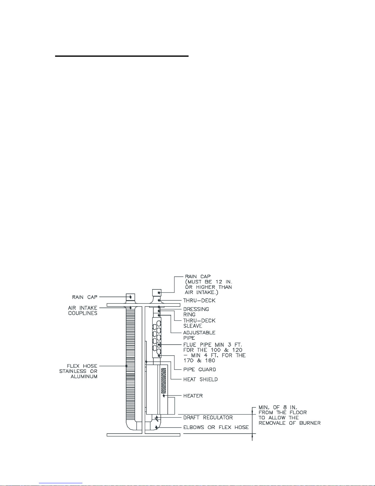
BALANCED DRAFT SYSTEM
The Balanced Draft System is optional; it is not required but can be added later if you wish.
The Balanced Draft has 2 major advantages. In most cases it will eliminate “back drafting or
down drafting” (Page 8) and allows the heater to use outside air for combustion rather than cabin
air. This increases the safety and efficiency of the heater. The balanced draft system can be
mounted on all our heaters No. 100, 120, 170, and 180. Unfortunately it can not be mounted on
the No. 200 and 250 stove.
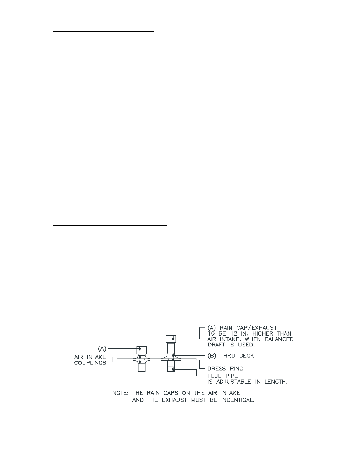
The Balanced Draft is simply having the air feed for the heater coming from outside the boat
immediately adjacent to the exhaust pipe.
This means that any wind conditions that affect the exhaust will affect the air intake
simultaneously - thus a balanced draft. Similarly the heater will not experience any barometric
pressure changes in the boat because the air intake for the heater is through the 3” opening in the
bottom that is connected to the outside air through the air intake and the 3” hose. The air intake
must be as close to the exhaust as possible - no more than 3 feet away and free of all
obstructions. We want the intake and exhaust to experience the same conditions. The exhaust
should be approximately 12” higher than the intake. The air intake hose should be as short as
possible with as few elbows and bends as possible. We want a smooth flow of air to the heater.
The size of the hose for the air intake must be 3” - the same as the exhaust pipe. The Rain Caps
on the exhaust and the air intake must be identical.
If installing the Balanced Draft, the intake pipe may be 3” hi-heat flex hose, stainless steel
or aluminum pipe.
SIG MARINE PRODUCTS MANUAL REV S1
4
Page 5
THINGS TO CONSIDER
1. Minimum flue pipe length is 3 feet for the 100 and 120, 4 feet for the 170, 180, 190, 200 and
250. This is the absolute minimum.
2. The maximum angle of any bend in the stack is 45 Degrees.
3. If installing the Balanced Draft, the air intake must be mounted within a 3-foot radius of the
Rain Cap on the cabin top for proper operation.
4. If installing a heater in a sailboat and planning to use while under heel, see “Sailboat
Mounting” (page 6).
5. If you are going to use a small electric fuel pump to supply fuel to the heater, the maximum
pressure is 3 PSI. If installing a gravity day tank, the bottom of the tank must be 12” above the
knob on the metering valve. Remember to take the angle of the heel into consideration.
6. Installation of our exhaust Thru Deck will require a 5” diameter hole to be cut in the cabin top.
If installing the Air Intake for a Balanced Draft, a 3” hole will be required for all heaters. The
190, 200 and 250 stoves require a 6” diameter hole for a 4” flue pipe and a 7” diameter hole for a
5” flue pipe.
7. If deck is curved or sloped, you may need a shim pad to mount the Thru Deck and Air Intake
Couplings.
HEATER INSTALLATION:
Mount the heater in the exact location you want it.
Our Thru Deck requires a 5” hole. If you are using another manufactures Thru Deck, follow their
recommendations for installation.
After you have measured down from the cabin top for the correct pipe length, you may use wood
screws, sheet metal screws or through bolts, on pipe and Thru Deck.
SIG MARINE PRODUCTS MANUAL REV S1
5
Page 6
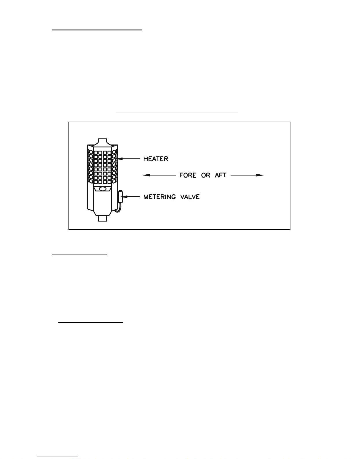
SAILBOAT MOUNTING
When installing the heater in a sailboat, it is important that the metering valve and the burner are
both in line with the keel to permit proper functioning of the heater when the boat heels.
If the heater is installed with the window facing fore or aft, the metering valve and burner will
already be in line with the keel and no additional actions are necessary.
If the heater is installed with the window facing port or starboard, the metering valve must be
repositioned. This must be done at our factory.
PORT / STARBOARD HEATER MOUNTING
FUEL SUPPLY
The requirements are 1/4” I.D. (U.S. Coast Guard Type B) fuel hose or equivalent or 1/4” I.D.
copper tubing for the fuel inlet and vent lines. The overflow should be run to a container away
from the heater, 1/4” I.D. clear PVC hose is desirable. Do not connect the overflow to your
engine return. Do not connect the overflow to the vent on the main fuel tank. You will almost
never get fuel out of the overflow. It is designed as a safety device for obstructions in the
metering valve. Before you start pulling tubing, let’s analyze the options you have:
1. GRAVITY FUEL TANK sometimes known as a day tank. This type of installation is the most
desirable if you have room. The tank bottom must be a minimum of 12” above the knob of the
metering valve, and no higher than 8 ft. The tank capacity should be at least 2 gallons, this
would give you about 48 hours of operation. The location of the tank can be almost anywhere
you want it to be (taking into consideration angle of heel when installed in a sailboat). The
benefits of a gravity tank are: no noise and no power draw. The disadvantage is limited fuel
capacity.
SIG MARINE PRODUCTS MANUAL REV S1
6
Page 7

2. ELECTRIC FUEL PUMP, this type of installation is a very common one, the advantages are;
it’s less expensive than a gravity tank and you can have full capacity of your main fuel tank. The
disadvantages are; power draw, noise, and loss of the heater in the case of the pump failure.
3. Some installations use both methods, a gravity tank to supply the heater and an electric or
manual fuel pump to fill the gravity tank.
Let’s do the installation of the gravity tank first. If you are planning to install an electric fuel
pump move on to Page 8.
The gravity tank, as you may have found, is not an item stocked by your local dealers. In fact
some don’t know what one is. So now what? Well, the easiest and actually the best method is to
have one made by your local Aluminum or Stainless Steel Fabrication Shop. This allows you to
custom make a tank to any particular area you have, getting the most gallonage from your area,
venting, mounting brackets, fuel fill, and the proper outlet size for the heater, all where you want
them. A manual shut off must be installed at the outlet of the tank and also one at the heater.
The vent line should be equal to or greater than the in and out-let.
Now that you have your tank, (be sure you use Coast Guard Type “B” fuel hose or equivalent for
all your fuel hoses). Connect the fuel fill. The vent line should be running to an outside fitting
above the tank. You may use copper tubing or a fuel line hose, for the fuel line to the heater and
for the vent. A small inline fuel filter and manual fuel shut off valve must be installed.
Try to route the fuel line with as few bends and with gentle bends as possible. The fuel filter and
the shut off valve should be mounted as close to the heater as possible.
SIG MARINE PRODUCTS MANUAL REV S1
7
Page 8
ELECTRIC FUEL PUMP INSTALLATION
The maximum pressure that our metering valve (carburetor) can withstand is 3 PSI. If more
than 3 PSI is used, fuel will flow out of the overflow outlet. In other words, the float in the
metering valve does not have enough buoyancy to close the needle seat and thus shut off the flow
of fuel. We recommend the Walbro fuel pump No. 2403-1. This is an adjustable pressure fuel
pump that comes preset at 2 1/2 PSI. Therefore, no adjustment is required. Walbro makes another
pump, No. 2403-1, which is not adjustable and comes preset between 4-6 PSI. If you use this
type of pump you will require a pressure-reducing regulator to reduce the pressure to 3 PSI.
You should obtain your fuel directly from the main tank. If this is not possible, you may “tee”
into the line after the main engine fuel filters before going to the engine. This eliminates the need
for an extra fuel filter, but you must still install a manual “shut off” valve. In addition, you must
install a “check valve” in the heater line to prevent the engine from drawing fuel and then air
through the metering valve on the heater. Also, you should install a “check valve” on the engine
fuel line so that the heater fuel pump does not draw fuel and then air from the engine.
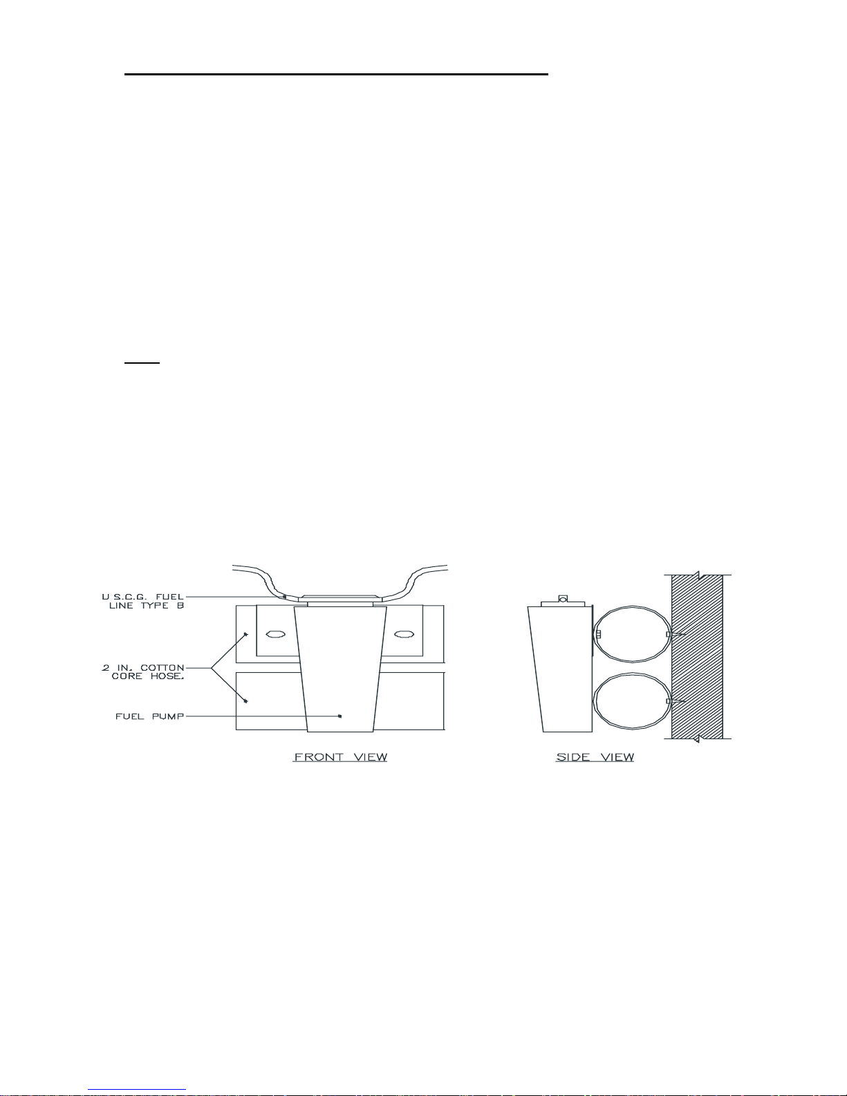
Noise: The fuel pump can be quite noisy. It does not operate continuously, only when there is a
demand for fuel, every few seconds, but it can be very annoying.
You can eliminate part of the noise by mounting two pieces of a good 2” cotton core exhaust
hose on the bulkhead. To do this, drill a hole all the way through both sides of the hose, the
correct size of fastenings you will use to secure the hose to the bulkhead. Now re-drill one side
with a drill the size of the fastenings to hold to the bulkhead, then fasten the pump to it. Now
mount the second piece so that the lower portion of the pump rests on the hose. Look at the
drawing.
Now that you have the pump mounted, connect the fuel pump with a piece of flexible fuel hose
or copper tubing to supply the heater but you should use a short piece of flexible fuel hose to
connect the copper tubing. This whole exercise is designed to isolate the fuel pump and reduce
the noise. Following the manufacturer’s recommendations is always best, although we
recommend the on-off switch close to the heater.
SIG MARINE PRODUCTS MANUAL REV S1
8
Page 9

“BACK DRAFTING” OR “DOWN DRAFTING”:
The reason this can occur is because of changes between inside and outside of your boat, caused
by windage coming from the sails or across the flying bridge and causing air turbulence on your
deck, which creates a high pressure area around the Rain Cap (exhaust pipe), and this can slow,
stop or reverse the “drafting “ of the heater or even extinguish the flame. Because the heater is
hot, the flame may re-ignite when the fuel flows into the burner. This will cause a loud “bang”
and maybe cause smoke or soot in your cabin.
Another reason this can occur is because of a negative pressure inside the boat, which is caused
by a hatch, or large port being open on the lee side of the boat. This will cause air to be siphoned
out and then the stovepipe (exhaust) will act as a vent to allow air into the boat. This down flow
of air in the exhaust pipe is referred to as “down drafting” and it may extinguish your flame.
When the flame re-ignites, there will be a “bang” and maybe soot or smoke.
Our “Balanced Draft” System (see Page 4) will solve a majority of these problems.
If you can not install the “Balance Draft” System, a “Draft Assist Fan” (Page 18) can help in off
setting down drafts.
Sometimes if you increase the length of stovepipe, (1-2 ft) it will off set the down draft.
FUEL:
Different types of fuel, Diesel No.1 and No.2 or kerosene can vary greatly depending on which
oil company supplied the fuel, time of year-summer vs. winter or which part of the world you are
in. This viscosity (thickness) can vary by as much as 50% when the temperature is 15 Degrees C.
(60 Degrees F.), the diesel may be slightly thicker than water, while at 5 Degrees C. (40 Degrees
F.), it may be like syrup. We have designed our metering valve so that adjustments can be made,
very easily (see problem 2,page 22). Perhaps you can simply set your heater to a higher or lower
setting between summer and winter without adjusting the metering valve adjustment screw.
SIG MARINE PRODUCTS MANUAL REV S1
9
Page 10

HEATER LIGHTING PROCEDURE
MATERIALS
To light the heater, you will need the following:
-A piece of toilet tissue or facial tissue (no paper towels!)
-Matches or a lighter.
- A 1 oz. container
HEATER LIGHTING STEPS
1. On the 100,120 and 170 open the small door inside. On the 180, 190, 200 and 250,
open the top or lid.
2. Pour 1 oz. of kerosene or alcohol into the burner.
Note: Alcohol will burn hotter and thus the preheat time is quicker than kerosene, but when you ignite the
alcohol, there will be a “poof” from the alcohol fumes---this may scare you, or singe your hair. Please be
careful! Also, it is difficult to see the alcohol burning and you may turn the fuel on prematurely e.g. before
the burner is fully preheated. This would cause a pool of fuel to form in the bottom of the burner and you
will get smoke because you are not burning “fuel vapors” --- just raw fuel.
3. Tear off a small piece of tissue, about 1 1/2” square and wipe out the 1 oz. measuring
container. The oil on the tissue will make it burn easier.
4. Light the fuel-soaked tissue and drop it into the burner, making sure that it lands in the
puddle of fuel. Be careful when using alcohol methyl hydrate.
5. Close the door or lid.
6. With the metering valve still “off”, let the heater burn until the puddle of fuel is almost
gone. (The flames will start to get smaller.) This is called the pre-heat cycle. It takes
approximately 8-10 minutes. But it could be as long as 12-15 minutes. This pre-heat cycle
will go through 3 stages.
7. When the puddle of fuel has almost burnt away, turn the metering valve to 3 or 4. The
size of the flames should start to burn towards the top of the burner (around the burner
ring).
For an illustration of the three stages of burner ignition, see the series of Drawings in Figure 8,
Stages of Burner Ignition.
Note: the single biggest error that people make when lighting the heater is to “ turn on” the fuel
before the burner is fully preheated. Wait until the flame dies down --- almost out, before turning
the fuel on.
A good combustion check can be done at any time during operation. Turn the valve to
“off”, after 60 seconds the flame will die down. Turn the fuel to the original setting before
it goes out.
If it doesn’t go out, it means that you have a “pool” of fuel in the burner --- this is caused by
turning the fuel “ON” before the burner is fully preheated.
Do not worry --- just keep the valve turned ‘off” until the diesel burns away and the flame starts
to die down. Then turn the valve to your regular setting -- probably 3 or 4.
If you are unable to get the flame to burn above the ring, refer to “Trouble Shooting Problem
#2 for Solution”(Page 22)
SIG MARINE PRODUCTS MANUAL REV S1
10
Page 11

FIGURE 8. STAGES OF BURNER IGNITION.
NOTE: Illustrations are for the 100 and 120. The 170,180, 190, 200 and 250 have a four post-
evaporating stem.
STAGE 1 A single flame rises up the side of the burner from the burning tissue. Some light
smoke from the rain cap is to be expected.
STAGE 2 Fuel is starting to vaporize and burn. Some light smoking will still be detected.
STAGE 3 In this stage, the flame is now up out of the burner with the base of the flame at
the level of the burner ring. This is the correct type of flame for a medium to high setting. On
a low setting, some of the flame will still be inside the burner. This is still correct. (See
Note).
NOTE: On the 170, 180, 200 and 250, the flame can be slightly below the ring and still get
good results. If the window should “soot up”, this indicates you are burning it too low--turn
valve to a higher number until the window stays clear. On the 100 and 120, the flame must
always be above the ring.
SIG MARINE PRODUCTS MANUAL REV S1
11
Page 12

METERING VALVE
ADJUSTMENT: Our metering valve is a very simple device and will require little
maintenance. However, because of the different fuel viscosity’s, some adjustments will
be necessary. See “Trouble Shooting” if necessary (page 22).
STORAGE
When storing the boat heater for long periods e.g. 2 or more months, while the stove is
“burning” turn off the fuel supply, and leave the metering valve in “on” position. This
will “burn” the fuel in the metering valve and leave the float and the metering stem in the
open position. We recommend this to save the rubber needle seat and “O” ring on the
metering stem from taking a “set” and maybe sticking or tearing.
SIG MARINE PRODUCTS MANUAL REV S1
12
Page 13

SIGMAR
THE METERING VALVE
TOP VIEW OF THE VALVE BODY EXPLODED VIEW OF NEEDLE & SEAT
CROSS SECTIONAL FRONT VIEW
OF METERING VALVE EXPLODED VIEW OF METERING VALVE
SIG MARINE PRODUCTS MANUAL REV S1
13
Page 14

CLEANING THE NO. 100 AND 120
Depending on the quality of the fuel that you use and how often you use the heater, some carbon
may build up around the legs of the vaporizing stem and on the inside of the burner.
You may clean the burner by reaching in through the door or by removing the burner.
TO REMOVE THE BURNER:
--Disconnect the fuel feed and the over-flow lines
--Remove screws “ A”, one on each side of the stainless housing and loosen the brass screw “B”
on the right side of the combustion chamber under the door with the window. The burner will
now drop out.
1. To clean the burner, first take out the burner ring, the brass vaporizing
stem and the stem holder. Next place a pan under the burner to catch the fuel when you remove
the 1/4” clean out plug in the bottom of the burner. Then clean out any carbon pieces in the
burner. You may have to use a scrapper to remove the build up of carbon. The base of the burner
should be free of any carbon so that the four feet of the brass vaporizing stem make “metal to
metal” contact with the base of the burner. Any carbon will act as an insulator and you will not
get a good heat transfer from the brass vaporizing stem to the base of the burner.
2. Next, use the auger supplied with the heater to ream out the burner oil inlet hole in the base of
the burner. Later after the burner is reinstalled and before you replace the 1/4” clean out plug,
flush out the system by turning on the metering valve (carburetor) and letting some fuel drip out
the bottom.
3. There are four rows of holes in the side of the burner. These must all be clean.
Use a No. 53 (0.059) drill bit to clean the two upper rows of holes and a No. 51 (0.067) drill bit
to clean the bottom two rows of holes.
“Never! Never! Never! Enlarge or alter these holes.
Do not use a rag to wipe the inside of the burner, because you will be pushing carbon into these
holes. If needed, use a wire brush.
Now replace the 1/4” clean out plug, be sure to use some sealer and don’t over tighten.
Replace the brass vaporizing stem and stem holder.
Be sure all four feet are flat on the bottom of the burner base.
Replace the burner ring. Note that the correct way is with the flange facing down.
Reconnect the fuel feed and overflow lines.
SIG MARINE PRODUCTS MANUAL REV S1
14
Page 15

CLEANING THE NO. 170.
Depending on the quality of the fuel that you use and how often you use the heater, some carbon
may build up around the base of the vaporizing stem and on the inside of the burner.
You may clean the burner by reaching in through the door or by removing the burner.
TO REMOVE THE BURNER:
--Disconnect the fuel feed and the over-flow lines
--Remove screws “ A”, one on each side of the stainless housing and loosen the brass screw “B”
on the right side of the combustion chamber under the door with the window. The burner will
now drop out.
1.To clean the burner, first take out the burner ring and the stainless steel 4 post-vaporizing stem.
Next place a pan under the burner to catch the fuel when you remove the 1/4” clean out plug in
the bottom of the burner. Then clean out any carbon pieces in the burner. You may have to use a
scrapper to remove the build up of carbon. The base of the burner should be free of any carbon so
that the four feet of the stainless steel vaporizing stem make metal to metal contact with the base
of the burner. Any carbon will act as an insulator and you will not get a good heat transfer from
the vaporizing stem to the base of the burner.
2.Next, use the auger supplied with the heater to ream out the burner oil inlet hole in the base of
the burner. Later after the burner is reinstalled and before you replace the 1/4” clean out plug,
flush out the system by turning on the metering valve(carburetor) and letting some fuel drip out
the bottom.
3.There are four rows of holes in the side of the burner. These must all be clean.
Use a No. 52 (0.063) drill bit to clean the upper two rows of holes and a No. 50(0.070) drill bit to
clean out the bottom two rows of holes.
“Never! Never! Never! Enlarge or alter these holes.
Do not use a rag to wipe the inside of the burner, because you will be pushing carbon into these
holes. If needed, use a wire brush.
Now replace the 1/4” clean out plug, be sure to use some sealer and don’t over tighten.
Replace the vaporizing inset. Replace the burner ring. Note that the correct way is with the flange
facing down.
Reconnect the fuel feed and overflow lines.
SIG MARINE PRODUCTS MANUAL REV S1
15
Page 16

CLEANING THE NO. 180, 200 AND 250 STOVE.
Depending on the quality of the fuel that you use and how often you use the heater, some carbon
may build up around the burner oil inlet and on the inside of the burner.
For the 180, it is much easier to clean the heater if you remove it from the boat. Then remove the
shroud from the heater. Then separate the upper part of the burner from the bottom, by removing
the 4 screws.
If you do not wish to remove the heater from your boat, you must reach down through the top to
clean the burner.
1.To clean the burner, first take out the burner ring and the stainless steel vaporizing insert. Next
place a pan under the burner to catch the fuel when you remove the 1/4” clean out plug in the
bottom of the burner. Then clean out any carbon pieces in the burner. You may have to use a
scrapper to remove the build up of carbon. The base of the burner should be free of any carbon so
that the four feet of the vaporizing stem make metal to metal contact with the base of the burner.
Any carbon will act as an insulator and you will not get a good heat transfer from the vaporizing
stem to the base of the burner.
2.Next, use the auger supplied with heater to ream out the burner oil inlet hole. After the burner
is reinstalled and before you replace the 1/4” clean out plug, flush out the system by turning on
the metering valve (carburetor) and letting some fuel drip out the bottom.
3.There are four rows of holes in the side of the burner. These must all be clean. Use a No.
52(.063) drill bit to clean the upper two rows of holes and a No. 50(.070) to clean the bottom two
rows of holes.
“Never! Never! Never! Enlarge or alter these holes.
Do not use a rag to wipe the inside of the burner, because you will be pushing carbon into these
holes. If needed use wire brush.
Now replace the 1/4” clean out plug, be sure to use some sealer and don’t over tighten.
Replace the vaporizing insert. Replace the burner ring. Note that the correct way is with the
flange facing down.
Reconnect the fuel feed and overflow lines.
SIG MARINE PRODUCTS MANUAL REV S1
16
Page 17

THE DRAFT ASSIST FAN (OPTION)
If you decide not to install the “Balanced Draft” System and you experience “back drafting”
or “down drafting” (see Page 9), the Draft Assist Fan is an option that may help solve the
problem. When using the Draft Assist Fan you must attempt to match the velocity of the fan
to the velocity of the wind in the down draft. The Draft Assist Fan mounts on the air intake
(bottom) of your heater. You must remove the “Draft Regulator” in order to install the Draft
Assist Fan.
SIG MARINE PRODUCTS MANUAL REV S1
17
Page 18

THE DRAFT REGULATOR
CUT-AWAY VIEW OF THE DRAFT REGULATOR
STANDARD ON ALL HEATERS- (NOT ON NO. 190, 200 AND 250 STOVES)
The Draft Regulator is located at the base of the heater and is provided as standard equipment on
all heaters-No. 100, 120, 170, and 180.
If you have too much exhaust pipe, you will have too much draft and the flame will be drawn
down into the burner. This will result in soot on the window, in the burner and ultimately in the
exhaust pipes.
The Draft Regulator is used to slow down the air (draft) entering the heater. The fine-tuning of
the draft will increase the heater’s efficiency and performance. This is more noticeable on low
setting. If you close the regulator (say 45 Degrees or even more if you have a long exhaust pipe)
on low setting, you may have to open it on medium and high setting - on higher setting you need
more air to get complete combustion.
SIG MARINE PRODUCTS MANUAL REV S1
18
Page 19

IMPORTANT!!! IMPORTANT!!! IMPORTANT!!!
At any time and after maintenance on the burner be sure to:
1. Insert the burner ring with the flange down. The burner ring must be seated fully down.
2. On the 100 and 120 heaters, insert the brass vaporizing stem flat on the bottom of the
burner base, making sure all four feet are flat on the bottom of the burner base. The legs
may not be flat after cleaning, therefore be sure to straighten them so the feet are flat on
the bottom of the burner base.
These two steps are very important to obtain proper vaporization of fuel. The heater will not
perform satisfactorily if these two steps are not followed carefully and correctly.
CUT AWAY VIEW OF THE 100/120 BURNER
SIG MARINE PRODUCTS MANUAL REV S1
19
Page 20

IMPORTANT!!! IMPORTANT!!! IMPORTANT!!!
At any time and after maintenance on the burner be sure to:
1. Insert the burner ring with the flange down. The burner ring must be seated fully down.
2. On the 170, 180, 190, 200 and 250 heaters, insert the vaporizing insert flat on the bottom
of the burner base. All four feet are flat on the bottom of the burner base. The legs may not
be flat after cleaning, therefore be sure to straighten them so the feet are flat on the bottom
of the burner base.
These two steps are very important to obtain proper vaporization of fuel. The heater will not
perform satisfactory if these two steps are not followed carefully and correctly.
CUT AWAY VIEW OF THE 170, 180, 190, 200 AND 250 BURNER
SIG MARINE PRODUCTS MANUAL REV S1
20
Page 21

TROUBLE SHOOTING
Theory of Operation
Note: The fire must always be burning above the ring on the 100 and 120 heaters!
Reason:
In order for the heater to not smoke, we have designed our burner to burn fuel vapors diesel, kerosene or stove oil. To do this, the flames surround the brass vaporizing stem
above the burner ring. The stem conducts heat to the base of the burner and heats it.
When the fuel enters the burner, through the hole in the center of the base of the burner, it
immediately turns to vapor. The fuel vapor mixes with air that enters through the four
rows of holes in the side of the burner and burns above the ring. If the heater is burning
too low, the flame will be below the ring, hence there will not be enough heat created to
heat the base of the burner and vaporize the fuel. If the heater is set too high, there will
not be enough air coming in through the holes to provide complete combustion with the
fuel, and hence the heater will smoke. If there is not enough heat or air for combustion the
mica window will get covered with soot and smoke may come out of the rain cap
(exhaust).
Problem #1: Fuel will not flow into the burner freely.
(This you can visually see when you remove the ring etc.)
1.1 Solution: If using a “Gravity Day Tank” check to see if there is fuel in the tank and
that the “shut off” is open. If using an electric pump check to see that it is” turned
on”.
1.2 Solution: The hole in the bottom (burner oil inlet) of the burner may be plugged. This
can be reamed out using the “auger” that came with the heater. You can either try to
clean the inlet hole by turning the auger into the inlet hole from the burner side (top)
like a corkscrew or if you feel that there is still dirt in the hole you can remove the
“clean out” plug in the bottom of the burner and “auger” the hole from the bottom of
the burner and the top. Run the auger all the way through. Clean the copper tube by
running a flexible wire through it.
1.3 Solution: Check to ensure that the rubber hose running from the metering valve
(carburetor) to the burner is not flattened. Although we use a thick wall rubber hose to
prevent flattening, this is still possible on older heaters. The hose flattens and does not
allow a full flow of fuel. You can check this by squeezing the hose at the bend to see
if the fuel flow increases. If this is the problem, replace the hose.
1.4 Check the “air” hole in the control knob and make sure it is “clear”.
SIG MARINE PRODUCTS MANUAL REV S1
21
Page 22

Problem #2: The flame is below the ring.
Solution: Increase the flow of fuel into the burner. This is done by turning the knob on the
metering valve (carburetor) to a higher number. Advance one or two numbers and then
wait approximately five minutes for the burner to stabilize. If the flame is still below the
ring advance one or two more numbers. Continue this process until the flame burns above
the ring.
If you reach Position 9 and the flame is still below the ring this means that the viscosity of
your fuel is thicker than the viscosity of the fuel that we used for calibrating the
carburetor valve. This is not a problem. We can increase the flow of fuel by turning the
fuel adjusting screw on the knob of the metering valve “in” (clockwise) while the heater
is still burning. Use the Allen Key that came with the heater and turn the fuel adjusting
screw in (clockwise) one complete turn. Wait approximately five minutes. The flame will
increase. If it is still below the ring, turn one more turn clockwise. Continue the
procedure until the flame is above the ring and no flame (fire) is below the ring. When
burning properly you should see NOTHING burning below the ring, only fuel vapors. On
the 170, 180, 190, 200 and 250 the flame can be slightly below the ring and still get good
results.
Now that you have the flame above the ring you must adjust (calibrate) the valve so that
the flame is just above the ring at approximately Number 3 setting, for “Low”. First turn
the knob to Number 6 and the flame will drop below the ring. Now turn the fuel adjusting
screw in (clockwise) one turn and wait five minutes. The flame will increase. If it is not
above the ring, similar to where it was before (at Number 9) then turn the screw in one
more turn (clockwise). Now that the flame is back to the same position at Number 6 as it
was at Number 9 we would like you to turn the knob to Number 3.
Again the flame will decrease and you must turn the fuel adjusting screw in (clockwise)
one full turn, the same as you did when you were calibrating at Number 6. Repeat until
you have the flame just above the ring at Number 3.
Now you have your heater calibrated for Number 3 to be the “Low Setting”. The “High”
setting should be approximately Number 7. Note: The operating range of our heater is
approximately four to five numbers. In other words, “Low” is Number 3, “High” is
Number 7. If you wished you could calibrate it where “Low” is Number 4 and “High” is
Number 8. This need to calibrate was caused by your fuel having a different viscosity to
the fuel, which we used, at the factory for calibration.
You may find that you must recalibrate between summer fuel and winter fuel or between
different fuel suppliers. Most of the time the only difference will be that ”Low” is
number 3 at one time and “Low” is Number 4 or 5 another time.
SIG MARINE PRODUCTS MANUAL REV S1
22
Page 23

Problem #3: When you turn the knob on the metering valve to “OFF”, the fuel
continues to flow into the burner.
Solution: Refer to the drawing on Page 14 of the Instruction Manual.
Note the “O” ring in the metering valve that shuts off the flow of oil, Item “O”. Check to
see that the “O” Ring is intact - e.g. not broken or missing or crimped. To check the “O”
Ring you must disassemble the metering valve. Note: be sure that the shut off to the
metering valve is turned off. Remove the four screws and lift off the knob and the top
plate. Note: When you disassemble the valve, fuel from the valve will flow into the
burner and before lighting the burner again, this fuel must be removed. This can be done
by using paper towel or rags as a “sponge”. If the “O” Ring is defective, contact your
local Sigmar dealer or the Sigmar Factory for a replacement.
Problem #4: Fuel flows out of the “overflow”.
Solution 4.1: If you are using a “pulse” pump, the pressure on the pump may be set too
high - maximum 3 PSI. If it is set too high, the float in the metering valve will not have
enough buoyancy to close the “needle seat” and stop the fuel flow in the valve. You must
adjust the pump pressure to be less than 3 PSI. If your pump is not adjustable, you will
require a pressure regulator.
Solution 4.2: You may have an obstruction holding the “needle seat” open. You must
remove the “needle seat” and check (see Page 14 for instructions on removal).
Solution 4.3: The float may be saturated. You can check this, by removing the control
knob and top (remove 4 screws). Plug the hole in the base of the metering valve with a
wooden pencil. Turn on the fuel. The float should “rise up” and turn off the fuel. If it
doesn’t check to see that it isn’t “jammed” and then contact factory for authorization to
return valve for re-building.
Problem #5: Flame is burning very “Lazy”.
Solution 5.1: This is caused by a shortage of air for combustion. Clean the 4 rows of air
holes in burner. For the Models 100 and 120, go to Page 15, Paragraph 3. For the Model
170, go to Page 16, Paragraph 3. For the Models 180, 190, 200 and 250, go to Page 17,
Paragraph 3. Note: Do not enlarge the holes.
Solution 5.2: If you have the “Balanced Draft” on your heater consider the following: If
you have a long run of “Air Inlet” hose, e.g. more than 4 - 5 feet, or if you have many
“twists” and “turns” in your hose this can cause a restriction in the flow in inlet air. You
can either shorten the length or straighten the run.
Solution 5.3: Check if “Draft Regulator” at bottom of the burner is “open” physically.
“Feel” to be sure “Draft Regulator” is open. The black knob on the regulator may have
slipped on the shaft and it may indicate that the “Regulator” is open while it may be
closed.
SIG MARINE PRODUCTS MANUAL REV S1
23
Page 24

SIG MARINE PRODUCTS MANUAL REV S1
24
Page 25

SIG-MA RINE PRO DUCTS L T D.
SIG MARINE PRODUCTS MANUAL REV S1
25
Page 26

SIG-MARINE PRODUCTS LTD.
SIG MARINE PRODUCTS MANUAL REV S1
26
Page 27

SIG-MARINE PRODUCTS LTD.
SIG MARINE PRODUCTS MANUAL REV S1
27
Page 28

ONE YEAR LIMITED WARRANTY
Manufacturer of the Sigmar cabin heaters does hereby warrant said product, to be free of defects
in workmanship and material for a period of one year from date of purchase. This warranty is
subject to, but not limited to the following exclusions and conditions:
1. Product has not been repaired, altered, misused or exposed to corrosive conditions.
2. Defective installation, operation, or maintenance contrary to the written instructions furnished
with the unit.
3. Any damage caused by soot, smoke, and leakage of fuel, odor or heat.
4.Warranty is provided to the original owner and is not transferable to other parties.
5. Repair or replacement of defective parts will be made available at the manufacturers designed
service representative. Owner, not the manufacturer, shall be responsible for the return of
defective parts, and payment of all delivery, installation and removal charges.
LIMITATION OF IMPLIED WARRANTIES
The foregoing warranty is exclusive and in lieu of all other warranties, oral or written, expressed
or implied; but not limited to any warranty of merchantability or fitness for a particular purpose.
LIMITATION OF LIABILITY
In no event shall the manufacturer be liable for any incidental or consequential damages, or
personal injury related to the product. Some do not allow the exclusion or limitation of incidental
or consequential damages so the above limitation or exclusive may not apply to you. This
warranty gives you specific legal rights, and you may also have other rights, which may vary.
CLAIMS PROCEDURE
The original owner, upon discovering a defect must notify the manufacturer’s designated service
representative in writing, including model, serial number, date and proof of purchase, and nature
of problem.
SIG MARINE PRODUCTS LTD.
23080 HAMILTON ROAD,
RICHMOND, B.C.
CANADA
V6V 1C9
PHONE: 800 663 8515 OR 604 522 0233
FAX: 604 522 9608
EMAIL: iallen@uniserve.com
IMPORTANT: OWNER SHALL KEEP THIS CERTIFICATE!
SIG MARINE PRODUCTS MANUAL REV S1
28
 Loading...