

Page 1
Translation of the original operating manual
sb
08/2012
Rev. 2.5 of 02/07/2018
Sigma 8KS;Refrigerated Centrifuge;Sigma 8KBS
Refrigerated Centrifuge
part no. 0702502
Sigma 8KS
Sigma 8KBS
from serial no. 162923
Refrigerated Centrifuge
Operating Manual
Please retain for later use!
Page 2

Refrigerated Centrifuge Sigma 8KS
Refrigerated Centrifuge Sigma 8KBS
2 / 131
Version 08/2012, Rev. 2.5 of 02/07/2018 • sb
Translation of the original operating manual, part no. 0702502
Page 3

Refrigerated Centrifuge Sigma 8KS
Refrigerated Centrifuge Sigma 8KBS
Version 08/2012, Rev. 2.5 of 02/07/2018 • sb
3 / 131
Translation of the original operating manual, part no. 0702502
In case of inquiries, please state the following numbers:
Order number:
Serial number:
© Copyright by
Sigma Laborzentrifugen GmbH
An der Unteren Söse 50
37520 Osterode am Harz
Germany
Tel.: +49 (0) 5522 / 5007-0
Fax: +49 (0) 5522 / 5007-12
Web: www.sigma-zentrifugen.de
E-mail: [email protected]
Page 4

Refrigerated Centrifuge Sigma 8KS
Refrigerated Centrifuge Sigma 8KBS
4 / 131
Version 08/2012, Rev. 2.5 of 02/07/2018 • sb
Translation of the original operating manual, part no. 0702502
Page 5

Refrigerated Centrifuge Sigma 8KS
Refrigerated Centrifuge Sigma 8KBS
Table of contents
Version 08/2012, Rev. 2.5 of 02/07/2018 • sb
5 / 131
Translation of the original operating manual, part no. 0702502
1 General information ............................................................................................................. 9
1.1 Importance of the operating manual .................................................................................. 9
1.2 Intended use ..................................................................................................................... 9
1.3 Warranty and liability......................................................................................................... 9
1.4 Copyright ........................................................................................................................ 10
1.5 Standards and regulations .............................................................................................. 10
1.6 Scope of supply .............................................................................................................. 10
2 Layout and mode of operation .......................................................................................... 11
2.1 Layout of the centrifuge .................................................................................................. 11
2.1.1 Functional and operating elements ............................................................................ 11
2.1.2 Name plate ................................................................................................................ 14
2.1.3 Mains plug ................................................................................................ ................. 15
2.2 Mode of operation ........................................................................................................... 16
2.2.1 Centrifugation principle .............................................................................................. 16
2.2.2 Area of application ..................................................................................................... 16
2.2.2.1 Speed, radius, and relative centrifugal force ...................................................... 17
2.2.2.2 Density ............................................................................................................... 17
3 Safety .................................................................................................................................. 18
3.1 Marking of the unit ................................ .......................................................................... 18
3.2 Explanation of the symbols and notes ............................................................................. 19
3.3 Responsibility of the operator .......................................................................................... 20
3.4 Operating personnel ....................................................................................................... 20
3.5 Informal safety instructions ............................................................................................. 20
3.6 Safety instructions .......................................................................................................... 21
3.6.1 Electrical safety ......................................................................................................... 21
3.6.2 Mechanical safety ...................................................................................................... 21
3.6.3 Fire prevention ........................................................................................................... 22
3.6.4 Chemical and biological safety .................................................................................. 22
3.6.5 Safety instructions for centrifugation .......................................................................... 23
3.6.6 Resistance of plastics ................................................................................................ 23
3.6.7 Rotors and accessories ............................................................................................. 24
3.6.7.1 Lifting and carrying rotors ................................................................................... 24
3.6.7.2 Service life ................................................................ ......................................... 24
3.6.7.3 Marking ................................................................................................ .............. 25
3.7 Safety devices ................................................................................................................ 26
3.7.1 Lid lock device ........................................................................................................... 26
3.7.2 Standstill monitoring system ...................................................................................... 26
3.7.3 System check ............................................................................................................ 26
3.7.4 Earth conductor check ............................................................................................... 26
3.7.5 Imbalance monitoring system .................................................................................... 26
3.7.6 Temperature monitoring system ................................................................................ 26
3.7.7 Rotor monitoring system ............................................................................................ 26
3.8 Measures in the event of hazards and accidents ............................................................ 27
Page 6

Refrigerated Centrifuge Sigma 8KS
Refrigerated Centrifuge Sigma 8KBS
Table of contents
6 / 131
Version 08/2012, Rev. 2.5 of 02/07/2018 • sb
Translation of the original operating manual, part no. 0702502
3.9 Remaining hazards ......................................................................................................... 27
4 Storage and transport ....................................................................................................... 28
4.1 Dimensions and weight ................................................................................................... 28
4.2 Storage conditions .......................................................................................................... 28
4.3 Notes on transport ................................ .......................................................................... 28
4.4 Packaging ....................................................................................................................... 29
5 Set-up and connection ...................................................................................................... 33
5.1 Installation site ................................................................................................................ 33
5.2 Set-up and alignment of the centrifuge ........................................................................... 33
5.2.1 Set-up ........................................................................................................................ 34
5.2.2 Alignment .................................................................................................................. 34
5.3 Installation of the cover holder ........................................................................................ 36
5.4 Power supply .................................................................................................................. 37
5.4.1 Type of connectiont ................................................................................................... 37
5.4.2 Customer-provided fuses ........................................................................................... 37
5.4.3 Power isolating device ............................................................................................... 37
5.5 Condensate drain ........................................................................................................... 38
5.6 Special equipment: water cooling system ....................................................................... 39
6 Using the centrifuge .......................................................................................................... 40
6.1 Initial start-up .................................................................................................................. 40
6.2 Switching the centrifuge on ............................................................................................. 40
6.2.1 Opening and closing the lid ........................................................................................ 40
6.2.2 Installation of rotors and accessories ......................................................................... 41
6.2.2.1 Installation of a rotor .......................................................................................... 41
6.2.2.2 Installation of an angle rotor with a hermetic lid .................................................. 41
6.2.2.3 Installation of accessories .................................................................................. 42
6.2.2.4 Adapters ............................................................................................................ 43
6.2.2.5 Vessels .............................................................................................................. 43
6.2.2.6 Blood bag systems ............................................................................................. 44
6.3 Control system "Spincontrol S" ....................................................................................... 45
6.3.1 User interface ............................................................................................................ 45
6.3.2 Manual mode ............................................................................................................. 46
6.3.2.1 Starting a centrifugation run ............................................................................... 46
6.3.2.2 Interrupting a centrifugation run ......................................................................... 46
6.3.2.3 Interrupting a deceleration process .................................................................... 46
6.3.2.4 Selection, display, and modification of data ........................................................ 46
6.3.2.5 Standard menu .................................................................................................. 47
6.3.2.6 Process library menu ......................................................................................... 53
6.3.2.7 Parameters menu .............................................................................................. 54
6.3.2.8 Setup menu ....................................................................................................... 58
6.3.2.9 Curve menu ....................................................................................................... 61
6.3.2.10 Option: Barcode menu ....................................................................................... 62
6.3.2.11 Help menu ......................................................................................................... 64
6.3.2.12 Changing the contrast ........................................................................................ 65
Page 7

Refrigerated Centrifuge Sigma 8KS
Refrigerated Centrifuge Sigma 8KBS
Table of contents
Version 08/2012, Rev. 2.5 of 02/07/2018 • sb
7 / 131
Translation of the original operating manual, part no. 0702502
6.3.3 Program mode ........................................................................................................... 65
6.3.3.1 Saving a program ............................................................................................... 66
6.3.3.2 Loading a program ............................................................................................. 66
6.3.3.3 Executing a program .......................................................................................... 67
6.3.3.4 Deleting a program ............................................................................................ 67
6.3.3.5 Automatic program rotation ................................................................................ 68
6.3.4 Options for data input and output ............................................................................... 69
6.4 Switching the centrifuge off ............................................................................................. 69
7 Malfunctions and error correction .................................................................................... 70
7.1 General malfunctions ...................................................................................................... 70
7.1.1 Emergency lid release ............................................................................................... 71
7.2 Table of error codes ........................................................................................................ 72
7.3 Service contact ............................................................................................................... 73
8 Maintenance and service ................................................................................................... 74
8.1 Maintenance ................................................................................................................... 74
8.1.1 Centrifuge .................................................................................................................. 74
8.1.1.1 Condenser (only refrigerated centrifuges with an air-cooled refrigeration system) ..
.......................................................................................................................... 75
8.1.2 Accessories ............................................................................................................... 75
8.1.2.1 Plastic accessories ............................................................................................ 76
8.1.3 Rotors, buckets and carriers ...................................................................................... 76
8.1.4 Load bearing bolts ................................................................................................ ..... 77
8.1.5 Glass breakage ......................................................................................................... 78
8.2 Sterilisation and disinfection of the rotor chamber and accessories ................................ 78
8.2.1 Autoclaving ................................................................................................................ 79
8.3 Service ........................................................................................................................... 80
8.4 Return of defective centrifuges or parts .......................................................................... 81
9 Disposal .............................................................................................................................. 83
9.1 Disposal of the centrifuge ............................................................................................... 83
9.2 Disposal of the packaging ............................................................................................... 83
10 Technical data .................................................................................................................... 84
10.1 Ambient conditions ......................................................................................................... 85
10.2 Technical documentation ................................................................................................ 85
Page 8

Refrigerated Centrifuge Sigma 8KS
Refrigerated Centrifuge Sigma 8KBS
Table of contents
8 / 131
Version 08/2012, Rev. 2.5 of 02/07/2018 • sb
Translation of the original operating manual, part no. 0702502
11 Appendix ............................................................................................................................ 86
11.1 Range of accessories ..................................................................................................... 86
11.1.1 Rotor radii .................................................................................................................. 86
11.2 Speed-gravitational-field-diagram ................................ ................................................... 87
11.3 Acceleration and deceleration curves ............................................................................. 88
11.4 Table of the service life of rotors and accessories ........................................................... 90
11.5 Resistance data .............................................................................................................. 91
11.6 Serial Control Interface Specification .............................................................................. 95
11.7 EC declaration of conformity ......................................................................................... 121
11.8 Declaration of conformity – China RoHS 2 .................................................................... 123
11.9 Layout plan ................................................................................................................... 125
12 Index ................................................................................................................................. 127
Page 9

Refrigerated Centrifuge Sigma 8KS
Refrigerated Centrifuge Sigma 8KBS
1 General information
Version 08/2012, Rev. 2.5 of 02/07/2018 • sb
9 / 131
Translation of the original operating manual, part no. 0702502
Pos: 1 /100 Sigma/100 BA Zentrifugen Sig ma (Standardmodule)/010 Allgemeine Informationen/010 Allgemeine Infor mationen ==================================== @ 26\mod_1405318948131_68.docx @ 191680 @ 1 @ 1
1 General information
Pos: 2 /100 Sigma/100 BA Zentrifugen Sig ma (Standardmodule)/010 Allgemeine Informationen/010-0010 Stellenwert der Betriebsanleitung------------------------------------------------------- @ 26\mod_1405318949962_68.docx @ 191694 @ 2 @ 1
1.1 Importance of the operating manual
A fundamental requirement for the safe and trouble-free operation of the
centrifuge is to be familiar with the fundamental safety instructions and all
possible hazards.
The operating manual includes important information concerning the safe
operation of the centrifuge.
This operating manual and, in particular, the notes on safety and hazards
must be observed by all persons operating the centrifuge.
In addition, the local rules and regulations for the prevention of accidents
Pos: 3 /010 Universalmodule/ Leerzeile @ 0 \mod_1202116244500_0.docx @ 114 @ @ 1
Pos: 4 /100 Sigma/100 BA Zentrifugen Sig ma (Standardmodule)/010 Allgemeine Informationen/010-0020 Bestimmungsg emäße Verwendung Sigma ------------------------------------------- @ 26\mod_1405318951312_68.docx @ 191709 @ 2 @ 1
must be complied with.
1.2 Intended use
Centrifuges are power-driven machines that separate liquids from solid
matter, liquid mixtures, or solid mixtures by centrifugal force. They are
solely intended for this purpose. Any other use beyond this area of
application is regarded as improper use. Sigma Laborzentrifugen GmbH
cannot be held liable for any damage resulting from such improper use.
The intended use also includes
• observation of all the notes and instructions included in the operating
manual and
Pos: 5 /010 Universalmodule/ Leerzeile @ 0 \mod_1202116244500_0.docx @ 114 @ @ 1
Pos: 6 /100 Sigma/100 BA Zentrifugen Sig ma (Standardmodule)/010 Allgemeine Informationen/010-0030 Gewährleistu ng und Haftung-------------------------------------------------- @ 26\mod_1405318955234_68.docx @ 191737 @ 2 @ 1
• compliance with the care, cleaning, and maintenance instructions.
1.3 Warranty and liability
The warranty and liability are subject to our "General Conditions" that were
distributed to the operator upon the conclusion of the contract.
Warranty and liability claims are excluded if they are due to:
• improper use.
• non-compliance with the safety instructions and hazard warnings in the
operating manual.
• improper installation, start-up, operation, or maintenance of the
Pos: 7 /010 Universalmodule/Seitenwechs el @ 0\mod_1202116244312_0.doc x @ 105 @ @ 1
centrifuge.
Page 10

Refrigerated Centrifuge Sigma 8KS
Refrigerated Centrifuge Sigma 8KBS
1 General information
10 / 131
Version 08/2012, Rev. 2.5 of 02/07/2018 • sb
Translation of the original operating manual, part no. 0702502
• 1 square spanner, size 8 (door)
Part no. 930 114
• 1 open spanner, size 8/10
(adjustable feet front side)
Part no. 930 015
• 1 open spanner, size 24
(adjustable feet rear side)
Part no. 930 024
• 1 wrench, angulate, size 17/19 (rotor)
Part no. 26 448
• 1 tube wrench (emergency release)
Part no. 930 110
• 1 wrench, hex socket, size 4 (rotor)
Part no. 930 050
• 1 holder for the rotor cover
with hexagon socket head screw (M6x16)
(see chapter 5.3 - "Installation of the cover
holder")
Part no. 28 598
Part no. 964 216
• 1 hose connector for condensate drain (installed)
Part no. 80 415
• 1 tube (30 g) heavy-duty grease for load-bearing
bolts
Part no. 71 401
Pos: 8 /100 Sigma/100 BA Zentrifugen Sig ma (Standardmodule)/010 Allgemeine Informationen/010-0040 Urheberrecht Sigma ----------------------------------------------------------------- @ 26\mod_1405318956858_68.docx @ 191751 @ 2 @ 1
1.4 Copyright
The copyright concerning the operating manual remains with
Sigma Laborzentrifugen GmbH.
The operating manual is solely intended for the operator and their
personnel. It includes instructions and information that must not be
• duplicated,
• distributed, or
• communicated in any other way.
Pos: 9 /010 Universalmodule/ Leerzeile @ 0 \mod_1202116244500_0.docx @ 114 @ @ 1
Pos: 10 /100 Sigma/100 BA Zentrifugen Sigma (Standardmodule)/010 Allgemein e Informationen/010-0050 Normen u nd Vorschriften------------------------------------------------------ @ 26\mod_1405318958202_68.docx @ 191765 @ 2 @ 1
Non-compliance may be prosecuted under criminal law.
1.5 Standards and regulations
EC declaration of conformity
Pos: 11 /010 Universalmodule/ Leerzeile @ 0\mod_1202116244500_0.docx @ 11 4 @ @ 1
Pos: 12 /100 Sigma/110 BA Zentrifugen Sigma (Projekte)/8KS_8KBS_8KHBS/010 Allgemeine Informationen/010-0 060 Lieferumfang------------------------------------------------------------------- @ 29\mod_1405327319254_68.docx @ 199577 @ 2 @ 1
(see chapter 11.7 - "EC declaration of conformity")
1.6 Scope of supply
The centrifuge comprises:
Documentation
Operating manual incl. EC declaration of conformity
(see chapter 11.7 - "EC declaration of conformity")
Accessories
Pos: 13 /010 Universalmodule/Abschnitts wechsel @ 0\mod_1202124514062_0.d ocx @ 418 @ @ 1
Pos: 14 /010 Universalmodule/Seitenwec hsel @ 0\mod_1202116244312_0.doc x @ 105 @ @ 1
according to your order, our order confirmation, and your delivery note.
Page 11
Refrigerated Centrifuge Sigma 8KS
Refrigerated Centrifuge Sigma 8KBS
2 Layout and mode of operation
Version 08/2012, Rev. 2.5 of 02/07/2018 • sb
11 / 131
Translation of the original operating manual, part no. 0702502
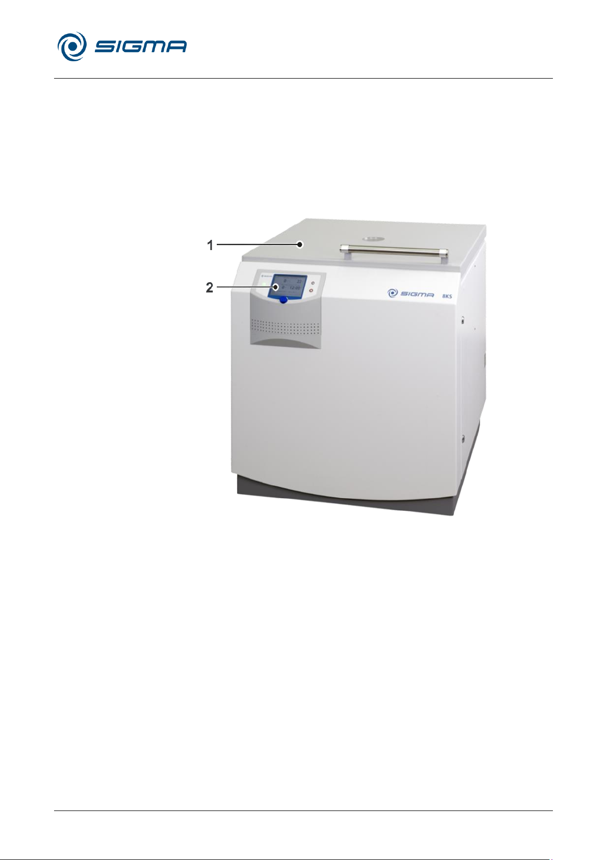
1 Lid
2 User interface (see
chapter 6.3.1 - "User
interface")
Pos: 15 /100 Sigma/100 BA Zentrifugen Sigma (Standardmodule)/020 Aufbau und Wirkungsweise/020 Aufbau und Wir kungsweise================================== @ 26\mod_1405318981820_68.docx @ 191779 @ 1 @ 1
2 Layout and mode of operation
Pos: 16 /100 Sigma/100 BA Zentrifugen Sigma (Standardmodule)/020 Aufbau und Wirkungsweise/020-0010 Aufbau d er Zentrifuge---------------------------------------------------- @ 26\mod_1405318982945_68.docx @ 191793 @ 2 @ 1
2.1 Layout of the centrifuge
Pos: 17 /100 Sigma/110 BA Zentrifugen Sigma (Projekte)/8KS_8KBS_8KHBS/020 Aufbau und Wirkungsweise/ 020- 0010-0011 Funktions- und Bedieneleme nte 8KS_8KBS flacher Deckel @ 46\mo d_1481275090610_68.docx @ 461577 @ 3 @ 1
2.1.1 Functional and operating elements
Fig. 1: Total view of the centrifuge
Page 12
Refrigerated Centrifuge Sigma 8KS
Refrigerated Centrifuge Sigma 8KBS
2 Layout and mode of operation
12 / 131
Version 08/2012, Rev. 2.5 of 02/07/2018 • sb
Translation of the original operating manual, part no. 0702502
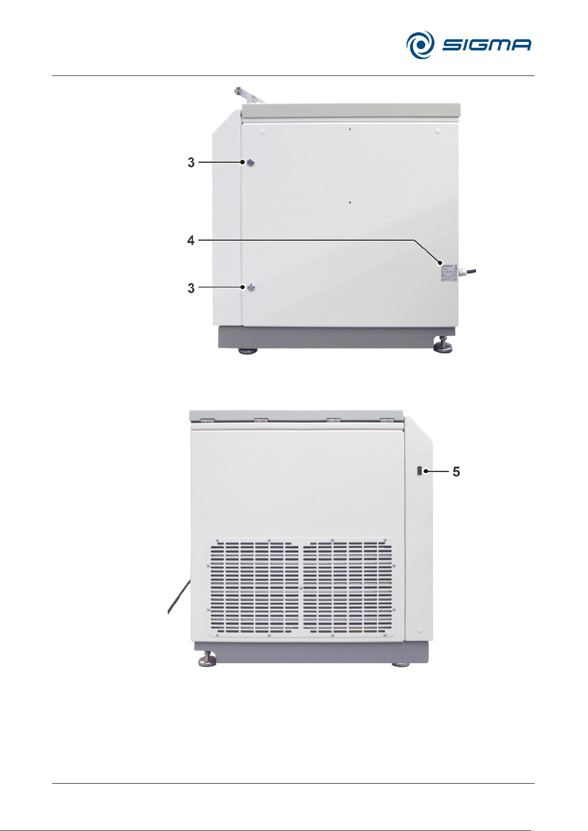
3 Locks of the front
door
4 Name plate (see
chapter 2.1.2 - "Name
plate")
5 Mains power switch
Fig. 2: Right side of the centrifuge
Fig. 3: Left side of the centrifuge
Page 13
Refrigerated Centrifuge Sigma 8KS
Refrigerated Centrifuge Sigma 8KBS
2 Layout and mode of operation
Version 08/2012, Rev. 2.5 of 02/07/2018 • sb
13 / 131
Translation of the original operating manual, part no. 0702502
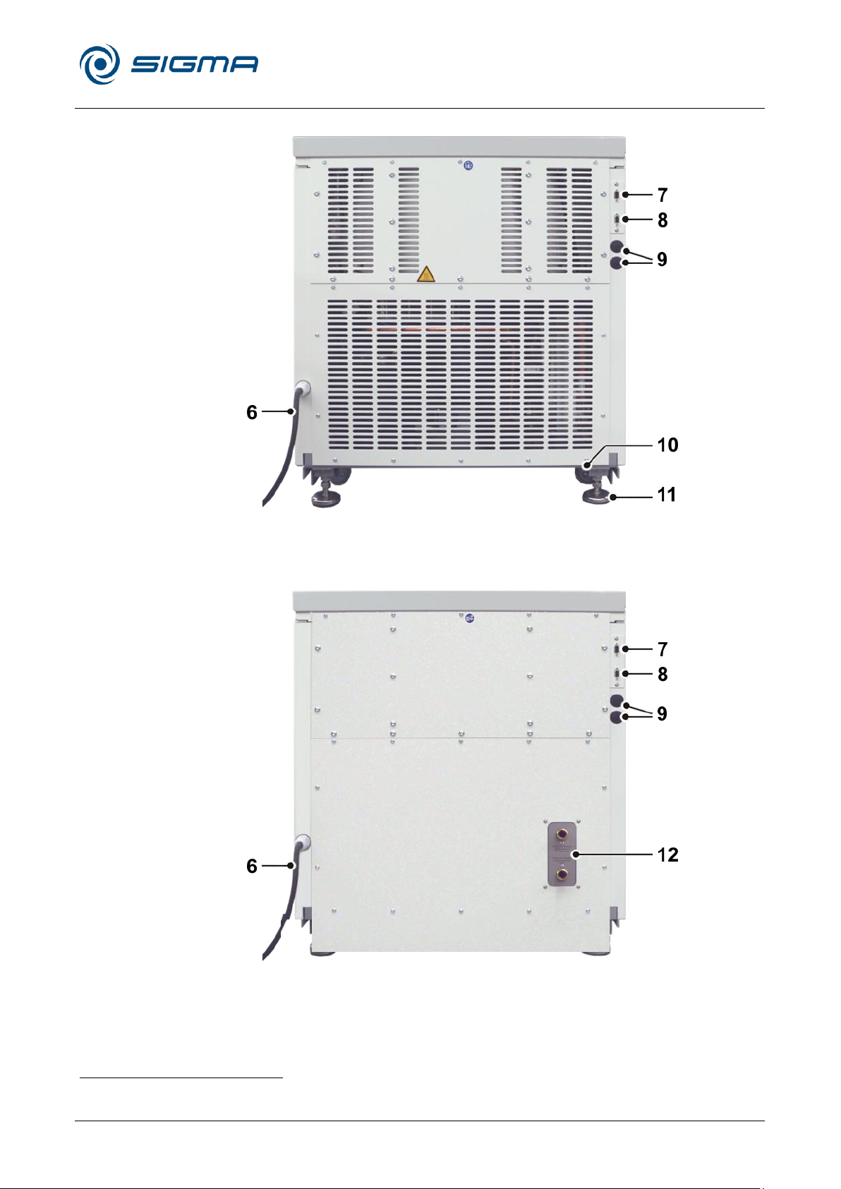
6 Mains cable
7 Option: connector for
barcode scanner
8 RS-232 interface
9 Option: serial
interface
(see chapter 6.3.4 -
"Options for data input
and output")
10 Castor
11 Adjustable foot
12 Cooling water
connection (see
chapter 5.6 - "Special
equipment: water
cooling system")
1
Pos: 18 /010 Universalmodule/ Leerzeile @ 0\ mod_1202116244500_0.docx @ 11 4 @ @ 1
Pos: 19 /100 Sigma/110 BA Zentrifuge n Sigma (Projekte)/8KS_8KBS_8KHBS /020 Aufbau und Wirkungsweise/020-0 010-0021 Typenschild 8KS_8KBS flac her Deckel @ 46\mod_1481610286 908_68.docx @ 461718 @ 3 @ 1
Fig. 4: Rear view of an air cooled centrifuge
Fig. 5: Rear view of a water cooled centrifuge1
Not for Sigma 8KB
Page 14
Refrigerated Centrifuge Sigma 8KS
Refrigerated Centrifuge Sigma 8KBS
2 Layout and mode of operation
14 / 131
Version 08/2012, Rev. 2.5 of 02/07/2018 • sb
Translation of the original operating manual, part no. 0702502
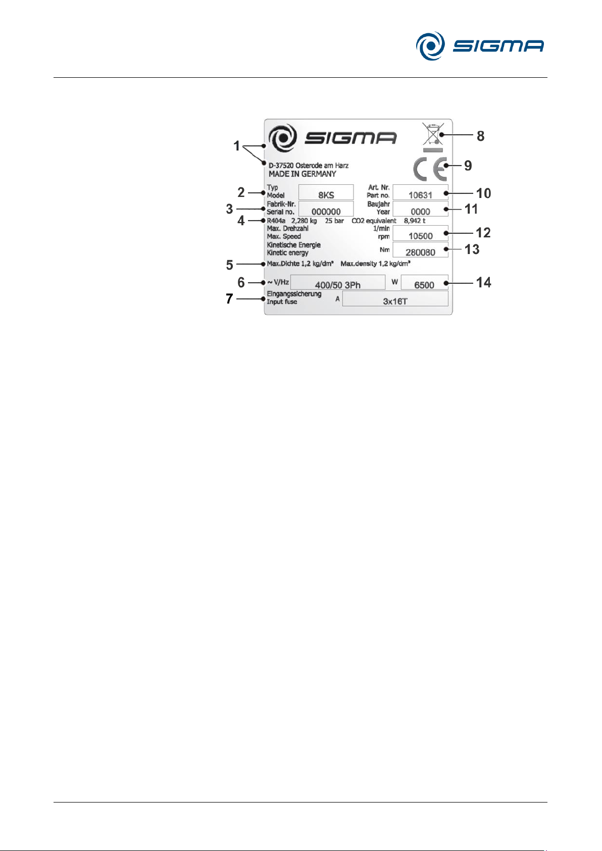
1 Manufacturer and
registered office
2 Type
3 Serial number
4 Refrigerant data
5 Max. density
6 Nominal voltage
7 Input fuse
8 Symbol for special
disposal (see chapter
9 - "Disposal")
9 CE mark in
compliance with the
directive 2006/42/EC
10 Part number
11 Year of manufacture
12 Max. speed
13 Max. kinetic energy
14 Power consumption
2.1.2 Name plate
Pos: 20 /010 Universalmodule/Seitenwec hsel @ 0\mod_1202116244312_0.doc x @ 105 @ @ 1
Fig. 6: Example of a name plate
Page 15
Refrigerated Centrifuge Sigma 8KS
Refrigerated Centrifuge Sigma 8KBS
2 Layout and mode of operation
Version 08/2012, Rev. 2.5 of 02/07/2018 • sb
15 / 131
Translation of the original operating manual, part no. 0702502
NOTE
If the centrifuge is operated within a different power supply network, it may
be necessary to replace the mains power plug.
The rotary field is of no importance when replacing the plug.
DANGER
Work on the power supply system must only be performed by certified
electricians!
Pos: 21 /100 Sigma/110 BA Zentrifuge n Sigma (Projekte)/8KS_8KBS_8KHBS/0 20 Aufbau und Wirkungsweise/020-00 10-0030 Netzstecker @ 29\mod_140 5327330313_68.docx @ 199619 @ 3 @ 1
2.1.3 Mains plug
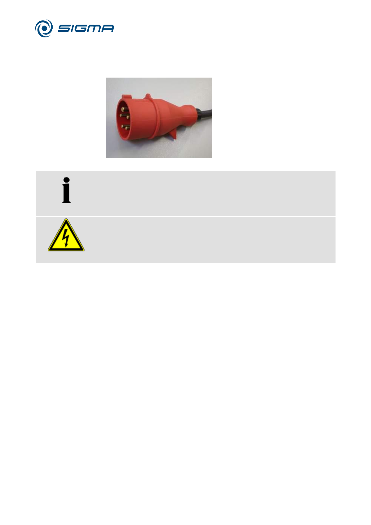
The centrifuge is equipped with a 5-pin Cekon plug (16 A).
Pos: 22 /010 Universalmodule/Seitenwec hsel @ 0\mod_1202116244312_0.doc x @ 105 @ @ 1
Fig. 7: 5-pin Cekon plug,16A
Page 16

Refrigerated Centrifuge Sigma 8KS
Refrigerated Centrifuge Sigma 8KBS
2 Layout and mode of operation
16 / 131
Version 08/2012, Rev. 2.5 of 02/07/2018 • sb
Translation of the original operating manual, part no. 0702502
Pos: 23 /100 Sigma/100 BA Zentrifugen Sigma (Standardmodule)/020 Aufbau und Wirkungsweise/020-0020 Wirkungsweise---------------------------------------------------------- @ 26\mod_1405318984194_68.docx @ 191 807 @ 2 @ 1
2.2 Mode of operation
Pos: 24 /100 Sigma/100 BA Zentrifugen Sigma (Standardmodule)/020 Aufbau und Wirkungsweise/020-0020-0010 Pri nzip der Zentrifugation @ 26\mod_14 05318985448_68.docx @ 191821 @ 3 @ 1
2.2.1 Centrifugation principle
Pos: 25 /010 Universalmodule/ Leerzeile @ 0\ mod_1202116244500_0.docx @ 11 4 @ @ 1
Pos: 26 /100 Sigma/100 BA Zentrifugen Sigma (Standardmodule)/020 Aufbau und Wirkungsweise/020-0020-0020 An wendungsbereich @ 26\mod_140531 8986763_68.docx @ 191835 @ 3 @ 1
Das
Centrifugation is a process for the separation of heterogeneous mixtures of
substances (suspensions, emulsions, or gas mixtures) into their
components. The mixture of substances, which rotates on a circular path, is
subject to centripetal acceleration that is several times greater than the
gravitational acceleration.
Centrifuges use the mass inertia inside the rotor chamber for separating the
substances. Due to their higher inertia, particles or media with a higher
density travel outwards. In doing so, they displace the components with a
lower density, which in turn travel towards the centre.
The centripetal acceleration of an object inside a centrifuge, as the effect of
centripetal force, depends on the distance between the object and the axis
of rotation as well as on the angular velocity. It increases linearly as a
function of the distance with regard to the axis of rotation and quadratically
as a function of the angular velocity. The bigger the radius in the rotor
chamber is and the higher the speed is, the higher the centripetal
acceleration is. However, the forces acting on the rotor also increase.
2.2.2 Area of application
Depending on the area of application of the centrifuge and also on the
particle size, solids content, and volume throughput of the mixture of
substances that is to be centrifuged, there are different types of centrifuges.
The areas of application go from household use as a salad spinner or
honey separator up to specialised technical applications in the clinical,
biological, or biochemical context:
• For numerous clinical examinations, cellular material must be separated
from the liquid to be analysed. The normal separation process can be
sped up considerably by using laboratory centrifuges.
• In the metal-working industry, centrifuges are used for separating oil
from metal cuttings. Dairies use centrifuges in order to separate cow’s
milk into cream and low-fat milk.
• Particularly big centrifuges are used in the sugar industry for separating
the syrup from the crystalline sugar.
• Ultracentrifuges are predominantly used in biology and biochemistry in
order to isolate particles, e.g. viruses. They are specifically designed for
high speeds up to 500,000 rpm. The rotor moves in a vacuum in order
Pos: 27 /010 Universalmodule/Seiten wechsel @ 0\mod_1202116244312_0.doc x @ 105 @ @ 1
to avoid air friction.
Page 17

Refrigerated Centrifuge Sigma 8KS
Refrigerated Centrifuge Sigma 8KBS
2 Layout and mode of operation
Version 08/2012, Rev. 2.5 of 02/07/2018 • sb
17 / 131
Translation of the original operating manual, part no. 0702502
)/2,1( Rho
Pos: 28 /100 Sigma/100 BA Zentrifugen Sigma (Standardmodule)/020 Aufbau und Wirkungsweise/020-0020-0020-001 0 Drehzahl, Radius, Relative Zentrifugalb eschleunigung @ 26\mod_1405318 988082_68.docx @ 191849 @ 4 @ 1
2.2.2.1 Speed, radius, and relative centrifugal force
The acceleration g, which the samples are subject to, can be increased by
increasing the radius in the rotor chamber and by increasing the speed.
These three parameters are interdependent and linked with each other via
the following formula:
Relative centrifugal force RCF = 11.18 x 10⁻⁶ x r x n2
r = radius in cm
n = speed in rpm
RCF without any dimension
If two values are entered, the third value is determined by way of the stated
formula. If, afterwards, the speed or the radius is changed, the resulting
relative centrifugal force will be recalculated automatically by the control
unit. If the RCF is changed, the speed will be adapted while the specified
radius is maintained.
The speed-gravitational-field-diagram provides an overview of the
relationship between speed, radius, and RCF (see chapter 11.2 - "Speed-
Pos: 29 /010 Universalmodule/ Leerzeile @ 0\ mod_1202116244500_0.docx @ 11 4 @ @ 1
Pos: 30 /100 Sigma/100 BA Zentrifugen Sigma (Standardmodule)/020 Aufbau und Wirkungsweise/020-0020-0020-002 0 Dichte @ 26\mod_1405318989359_6 8.docx @ 191863 @ 4 @ 1
gravitational-field-diagram").
2.2.2.2 Density
The laboratory centrifuge is suitable for the separation of constituents of
different densities in mixtures with a maximum density of 1.2 g/cm3. All
information concerning the speed of rotors and accessories refers to liquids
with a density corresponding to this specification. If the density is above this
value, the maximum permissible speed of the centrifuge must be reduced
based on the following formula:
n = n
Pos: 31 /010 Universalmodule/Abschnitts wechsel @ 0\mod_1202124514062_0.d ocx @ 418 @ @ 1
Pos: 32 /010 Universalmodule/Seitenwec hsel @ 0\mod_1202116244312_0.doc x @ 105 @ @ 1
Rho = density in g/cm3
max
x
Page 18
Refrigerated Centrifuge Sigma 8KS
Refrigerated Centrifuge Sigma 8KBS
3 Safety
18 / 131
Version 08/2012, Rev. 2.5 of 02/07/2018 • sb
Translation of the original operating manual, part no. 0702502
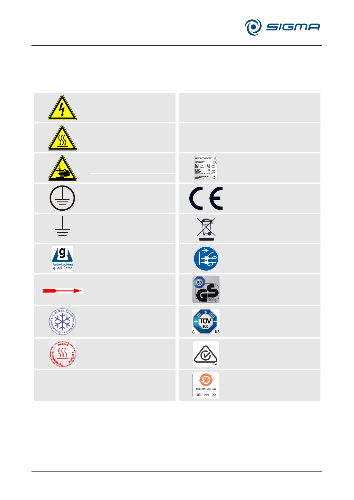
Dangerous voltage
I
On (Power)
Hot surface
0
Off (Power)
Caution! Risk of bruising
Name plate (see chapter
2.1.2 - "Name plate")
Protective earth (ground)
CE mark in compliance with
the directive 2006/42/EC
Earth (ground)
Do not dispose as part of
domestic waste
g-lock®-System installed
Unplug the mains plug
Arrow indicating the
direction of rotation
GS mark (tested safety;
only for Germany)
4°C Guarantee
NRTL mark (only for the
USA and Canada)
Centrifuge with heating
system
RCM mark
(only for Australia)
China RoHS 2 mark
(only for China)
Pos: 33 /100 Sigma/100 BA Zentrifugen Sigma (Standardmodule)/030 Sicher heit/030 Sicherheit============ =========================== @ 26\m od_1405319007254_68.docx @ 191877 @ 1 @ 1
3 Safety
Pos: 34 /100 Sigma/100 BA Zentrifugen Sigma (Standardmodule)/030 Sicherheit/0 30-0010 Beschilderung des Geräts ( außer 2-16KL, 3-16KL, 3-30KS, 4-16 S) @ 30\mod_1405404002477_68.doc x @ 203921 @ 2 @ 1
3.1 Marking of the unit
The following symbols are used for all types of centrifuges manufactured by Sigma:
Page 19
Refrigerated Centrifuge Sigma 8KS
Refrigerated Centrifuge Sigma 8KBS
3 Safety
Version 08/2012, Rev. 2.5 of 02/07/2018 • sb
19 / 131
Translation of the original operating manual, part no. 0702502
NOTE
Safety indications on the centrifuge must be kept readable at all times. If
necessary, they must be replaced.
NOTE
Not all of the symbols/labels are used for this centrifuge type.
DANGER
This symbol stands for a direct hazard to the life and health of persons.
Non-observance of these symbols causes serious health problems up to
life-endangering injuries.
DANGER
This symbol stands for a direct hazard to the life and health of persons
due to electrical voltage.
Non-observance of these symbols causes serious health problems up to
life-endangering injuries.
WARNING
This symbol stands for a potential hazard to the life and health of persons.
Non-observance of these symbols can cause serious health problems up
to life-endangering injuries.
CAUTION
This symbol indicates a potentially hazardous situation
Non-observance of these notes can cause minor injuries or damage to
property.
NOTE
This symbol indicates important information.
Pos: 35 /010 Universalmodule/ Leerzeile @ 0\ mod_1202116244500_0.docx @ 11 4 @ @ 1
Pos: 36 /100 Sigma/100 BA Zentrifuge n Sigma (Standardmodule)/030 Sicherheit /030-0020 Symbol- und Hinweiser klärungen @ 26\mod_1405319013955_68. docx @ 191947 @ 2 @ 1
3.2 Explanation of the symbols and notes
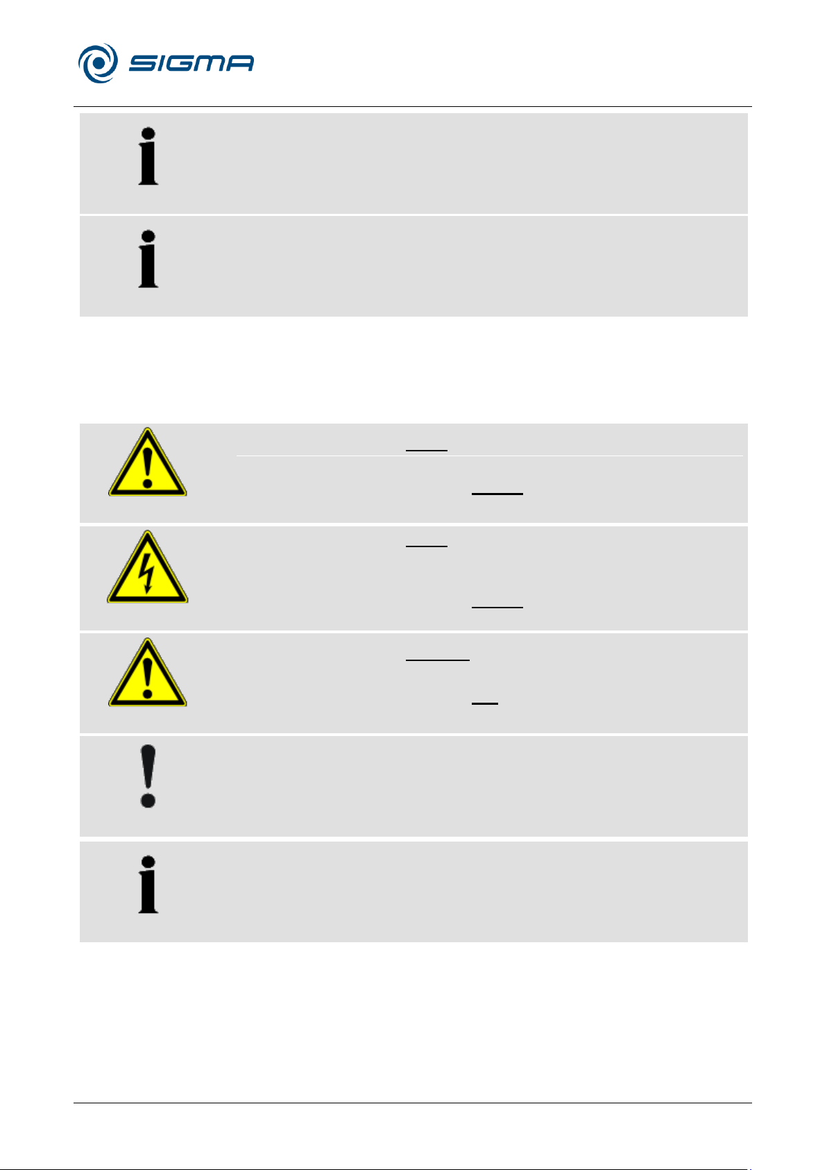
In this operating manual, the following names and symbols to indicate
hazards are used:
Pos: 37 /010 Universalmodule/Seitenwec hsel @ 0\mod_1202116244312_0.doc x @ 105 @ @ 1
Page 20

Refrigerated Centrifuge Sigma 8KS
Refrigerated Centrifuge Sigma 8KBS
3 Safety
20 / 131
Version 08/2012, Rev. 2.5 of 02/07/2018 • sb
Translation of the original operating manual, part no. 0702502
Pos: 38 /100 Sigma/100 BA Zentrifugen Sigma (Standardmodule)/030 Sicherheit/0 30-0030 Verantwortung des Betrei bers @ 26\mod_1405319015364_68.doc x @ 191961 @ 2 @ 1
3.3 Responsibility of the operator
The operator is responsible for authorising only qualified personnel to work
on the centrifuge (see chapter 3.4 - "Operating personnel").
The areas of responsibility of the personnel concerning the operation,
maintenance, and care of the unit must be clearly defined.
The safety-conscious work of the personnel in compliance with the
operating manual and the relevant EC and national health and safety
regulations as well as with the accident prevention regulations must be
checked at regular intervals (e.g. every month).
Under the international rules for health and safety at work, the operator is
obliged to:
• take measures in order to prevent all danger to life or health during
work.
• ensure that centrifuges are operated properly and entirely as intended
(see chapter 1.2 - "Intended use").
• take protective measures against fire and explosion when working with
hazardous substances.
Pos: 39 /010 Universalmodule/ Leerzeile @ 0\ mod_1202116244500_0.docx @ 11 4 @ @ 1
Pos: 40 /100 Sigma/100 BA Zentrifugen Sigma (Standardmodule)/030 Sicherheit/0 30-0040 Bedienpersonal @ 26\mo d_1405319017634_68.docx @ 191989 @ 2 @ 1
• take measures for the safe opening of centrifuges.
3.4 Operating personnel
Persons operating the unit must
• be familiar with the fundamental regulations concerning workplace
safety and accident prevention
• have read and understood this operating manual (and in particular the
safety sections and warning notes) and confirmed this with their
Pos: 41 /010 Universalmodule/ Leerzeile @ 0\ mod_1202116244500_0.docx @ 11 4 @ @ 1
Pos: 42 /100 Sigma/100 BA Zentrifugen Sigma (Standardmodule)/030 Sicherheit/0 30-0050 Informelle Sicherheitshin weise @ 26\mod_1405319019966_68.d ocx @ 192017 @ 2 @ 1
signature.
3.5 Informal safety instructions
• This operating manual is a part of the product.
• The operating manual must be kept at the location of use of the
centrifuge. Ensure that it is accessible at all times.
• The operating manual must be handed over to any subsequent owner
or operator of the centrifuge.
• Any changes, additions or updates received must be added to the
operating manual.
• In addition to the operating manual, the general and local rules and
regulations concerning the prevention of accidents and the protection of
the environment must also be supplied.
• Safety and danger indications on the centrifuge must be kept readable
Pos: 43 /010 Universalmodule/Seitenwec hsel @ 0\mod_1202116244312_0.doc x @ 105 @ @ 1
at all times. If necessary, they must be replaced.
Page 21
Refrigerated Centrifuge Sigma 8KS
Refrigerated Centrifuge Sigma 8KBS
3 Safety
Version 08/2012, Rev. 2.5 of 02/07/2018 • sb
21 / 131
Translation of the original operating manual, part no. 0702502
DANGER
• Ensure that the wall socket is properly wired and grounded.
• Check that the mains voltage agrees with the nominal voltage listed on
the name plate.
• Do not place vessels containing liquid on the centrifuge lid or within the
safety distance of 30 cm around the centrifuge. Spilled liquids may get
into the centrifuge and damage electrical or mechanical components.
• Work on the power supply system must only be performed by certified
electricians.
• Inspect the electrical equipment of the unit regularly. Defects such as
loose or burnt cables must be eliminated immediately.
WARNING
• Do not open the lid when the rotor is in motion!
• Do not reach into the rotor chamber when the rotor is in motion!
• Do not use the centrifuge if it was installed incorrectly.
• Do not use the centrifuge without panels.
• Do not use the centrifuge if the rotors and inserts show signs of
corrosion or other defects.
• Only use the centrifuge with rotors and accessories that have been
approved by the manufacturer. In case of doubt, contact the
manufacturer (see chapter 7.3 - "Service contact").
• Do not hold your fingers between the lid and the housing when closing
the lid. Risk of crushing!
• Defective lid relieving devices could cause the centrifuge lid to fall
(contact the service department, if necessary). Risk of crushing!
• Do not hit or move the centrifuge during its operation.
• Do not lean against or rest on the centrifuge during its operation.
• Do not spin any substances that could damage the material of the
rotors and buckets of the centrifuge in any way. Highly corrosive
substances, for example, damage the material and affect the
mechanical strength of the rotors and buckets.
• Stop the centrifuge immediately in the event of a malfunction. Eliminate
the malfunction (see chapter 7 - "Malfunctions and error correction") or
inform the service department of the manufacturer (see chapter 7.3 "Service contact").
• Ensure that all repairs are performed only by authorised and
specialised personnel.
Pos: 44 /100 Sigma/100 BA Zentrifugen Sigma (Standardmodule)/030 Sicherheit/0 30-0060 Sicherheitshinweise------------------------------------------------------------- @ 26\mod_1405319021480_68.docx @ 192031 @ 2 @ 1
3.6 Safety instructions
Pos: 45 /100 Sigma/100 BA Zentrifugen Sigma (Standardmodule)/030 Sicherheit/0 30-0060-0010 Elektrische Sicher heit @ 26\mod_1405319022891_68.doc x @ 192045 @ 3 @ 1
3.6.1 Electrical safety
To reduce the risk of electrical shock, the centrifuge uses a three-wire
electrical cord and plug to connect the equipment to earth-ground. To
Pos: 46 /010 Universalmodule/ Leerzeile @ 0\mod_1202116244500_0.docx @ 11 4 @ @ 1
Pos: 47 /100 Sigma/100 BA Zentrifugen Sigma (Standardmodule)/030 Sicherheit/0 30-0060-0020 Mechanische Sicher heit (außer 1-16/1-16K/1-7) @ 26\mod _1405319024314_68.docx @ 192059 @ 3 @ 1
preserve this safety feature:
3.6.2 Mechanical safety
In order to ensure the safe operation of the centrifuge, observe the
following:
Page 22
Refrigerated Centrifuge Sigma 8KS
Refrigerated Centrifuge Sigma 8KBS
3 Safety
22 / 131
Version 08/2012, Rev. 2.5 of 02/07/2018 • sb
Translation of the original operating manual, part no. 0702502
WARNING
• Prior to any start-up, check the centrifuge, rotor, and accessories for
signs of damage that can be discerned from the outside. Special
attention must be paid to all of the rubber parts (e.g. motor cover, lid
seal, and adapters) in terms of visible structural changes. Defective
parts must be replaced immediately.
• Open the centrifuge when it is not in use so that moisture can
evaporate.
DANGER
• Do not spin explosive or inflammable substances.
• Do not use the centrifuge within hazardous locations.
DANGER
• Infectious, toxic, pathogenic, and radioactive substances may only be
used in special, certified containment systems with a bio-seal in order
to prevent the material from being released.
• Take suitable precautions for your own safety if there is a risk of toxic,
radioactive, or pathogenic contamination
• Materials that chemically react with each other with a high level of
energy are prohibited.
WARNING
• Keep informed about local measures to avoid harmful emissions
(depending on the substances to be centrifuged).
• Protective clothing is not required for the operation of the centrifuge.
The materials to be centrifuged may, however, require special safety
measures (e.g. centrifugation of infectious, toxic, radioactive, or
pathogenic substances).
Pos: 48 /010 Universalmodule/ Leerzeile @ 0\mod_1202116244500_0.docx @ 11 4 @ @ 1
Pos: 49 /100 Sigma/100 BA Zentrifugen Sigma (Standardmodule)/030 Sicherheit/0 30-0060-0030 Brandschutz thermisc he Sicherungen @ 26\mod_14053190 25698_68.docx @ 192073 @ 3 @ 1
3.6.3 Fire prevention
Pos: 50 /010 Universalmodule/ Leerzeile @ 0\ mod_1202116244500_0.docx @ 11 4 @ @ 1
Pos: 51 /100 Sigma/100 BA Zentrifugen Sigma (Standardmodule)/030 Sicherheit/0 30-0060-0040 Chemische und bi ologische Sicherheit @ 26\mod_14053190 28141_68.docx @ 192101 @ 3 @ 1
3.6.4 Chemical and biological safety
If pathogenic, toxic, or radioactive samples are intended to be used in the
centrifuge, it is in the responsibility of the user to ensure that all necessary
safety regulations, guidelines, precautions, and practices are adhered to
accordingly.
Pos: 52 /010 Universalmodule/Seitenwec hsel @ 0\mod_1202116244312_0.doc x @ 105 @ @ 1
Page 23
Refrigerated Centrifuge Sigma 8KS
Refrigerated Centrifuge Sigma 8KBS
3 Safety
Version 08/2012, Rev. 2.5 of 02/07/2018 • sb
23 / 131
Translation of the original operating manual, part no. 0702502
WARNING
• Ensure that the centrifuge was set up properly (see chapter 5 - "Set-up
and connection").
• Maintain a safety distance of at least 30 cm (12 inches) around the
centrifuge.
• Do not store any dangerous goods in the centrifuge area.
• Do not stay in the safety area longer than what is absolutely necessary
for the operation of the centrifuge.
• Only use the centrifuge with rotors and accessories that have been
approved by the manufacturer. We explicitly warn against the use of
equipment of poor quality. Breaking glass or bursting vessels can
cause dangerous imbalances at high speeds
• Ensure that rotor and buckets are correctly fitted (see chapter 6.2.2.1 -
"Installation of a rotor").
• Observe the instructions on the installation of accessories (see chapter
6.2.2.3 - "Installation of accessories").
WARNING
• The rotor must be loaded in a rotationally symmetrical manner at equal
weights.
• If liquids with a density > 1.2 g/cm3 are used, reduce the speed (see
chapter 2.2.2.2 - "Density").
• Do not use the centrifuge if the rotor is loaded asymmetrically.
• Do not use the centrifuge with tubes that are excessively long.
NOTE
• Refer to the resistance data (see chapter 11.5 - "Resistance data")!
Pos: 53 /100 Sigma/100 BA Zentrifugen Sigma (Standardmodule)/030 Sicherheit /030-0060-0050 Sicherheitshinweise z ur Zentrifugation @ 26\mod_1405319 029632_68.docx @ 192115 @ 3 @ 1
3.6.5 Safety instructions for centrifugation
For safe operation, observe the following before starting the centrifuge:
Pos: 54 /010 Universalmodule/ Leerzeile @ 0\mod_1202116244500_0.docx @ 1 14 @ @ 1
Pos: 55 /010 Universalmodule/ Leerzeile @ 0\ mod_1202116244500_0.docx @ 11 4 @ @ 1
Pos: 56 /100 Sigma/100 BA Zentrifugen Sigma (Standardmodule)/030 Sicher heit/030-0060-0060 Beständigkeit von K unststoffen @ 26\mod_1405319031161_ 68.docx @ 192129 @ 3 @ 1
3.6.6 Resistance of plastics
Chemical influences have a strong effect on the polymeric chains of
plastics, and, therefore, on their physical properties. Plastic parts can be
Pos: 57 /010 Universalmodule/Seitenwec hsel @ 0\mod_1202116244312_0.doc x @ 105 @ @ 1
damaged if solvents, acids, or alkaline solutions are used.
Page 24
Refrigerated Centrifuge Sigma 8KS
Refrigerated Centrifuge Sigma 8KBS
3 Safety
24 / 131
Version 08/2012, Rev. 2.5 of 02/07/2018 • sb
Translation of the original operating manual, part no. 0702502
WARNING
All swing-out rotors applicable for this centrifuge and the angle rotor
12510 weigh more than 18 kg.
• Always lift the rotors with a lifting device or with a sufficient number
of people helping you.
WARNING
Perform regular checks (at least once per month) for safety reasons!
• Pay special attention to changes, such as corrosion, cracks, material
abrasion, etc.
• After 10 years, they must be inspected by the manufacturer.
• After 50,000 cycles, the rotor must be scrapped for reasons of safety.
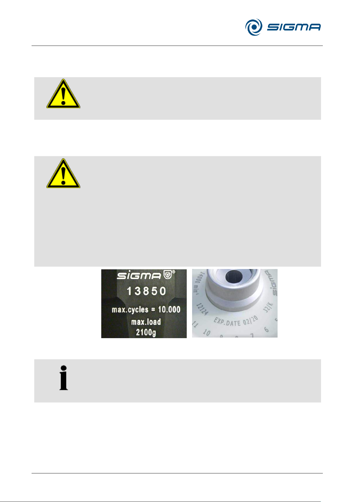
• If other data concerning the service life are engraved on the rotor or
bucket, these data shall apply accordingly. For example, a bucket with
the engraving "max. cycles = 10,000" has a service life of 10,000
cycles, and a rotor with the engraving "Exp. date 02/20" must be
scrapped in February 2020 at the latest (see figure).
• If a specification concerning the maximum number of cycles and a
specification concerning the service life (i.e. a date) are provided, the
specification that occurs first shall apply.
NOTE
• Refer to the table of rotors and accessories with a different service
life (see chapter 11.4 - " Table of the service life of rotors and
accessories ")!
Pos: 58 /100 Sigma/110 BA Zentrifugen Sigma (Projekte)/8KS_8KBS_8KHBS/030 Sicherheit/030-0060-0060 Rotor en und Zubehör @ 29\mod_14053273482 35_68.docx @ 199633 @ 3 @ 1
3.6.7 Rotors and accessories
Pos: 59 /100 Sigma/110 BA Zentrifugen Sigma (Projekte)/8KS_8KBS_8KHBS/030 Sicherheit/030-0060-0060-0010 H eben und Tragen von Rotoren @ 29\ mod_1405327348924_68.docx @ 19964 7 @ 4 @ 1
3.6.7.1 Lifting and carrying rotors
Pos: 60 /010 Universalmodule/ Leerzeile @ 0\mod_1202116244500_0.docx @ 114 @ @ 1
Pos: 61 /100 Sigma/100 BA Zentrifugen Sigma (Standardmodule)/030 Sicherheit/0 30-0060-0070-0010 Lebensdauer @ 26\mod_1405319032612_68.doc x @ 192143 @ 4 @ 1
3.6.7.2 Service life
The rotors and accessories have a limited service life.
Fig. 8: Different service life – engraving on the bucket/rotor
Pos: 62 /010 Universalmodule/Seitenwec hsel @ 0\mod_1202116244312_0.doc x @ 105 @ @ 1
Page 25
Refrigerated Centrifuge Sigma 8KS
Refrigerated Centrifuge Sigma 8KBS
3 Safety
Version 08/2012, Rev. 2.5 of 02/07/2018 • sb
25 / 131
Translation of the original operating manual, part no. 0702502
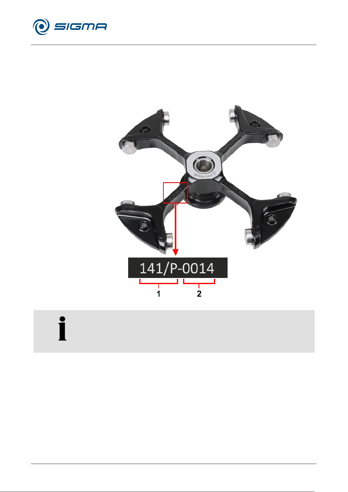
1 Batch number
2 Serial number
NOTE
If there are any enquiries concerning the rotor, please state the batch
number and serial number!
Pos: 63 /100 Sigma/100 BA Zentrifugen Sigma (Standardmodule)/030 Sicherheit/0 30-0060-0070-0020 Kennzeichnung @ 44\mod_1470119283352_68.docx @ 437025 @ 4 @ 1
3.6.7.3 Marking
During production, every rotor and bucket receives a batch number
enabling conclusions to be drawn concerning the production process and
the subsequent quality inspection. Some rotors also have an additional
serial number providing further detailed information.
The batch number and serial number is engraved on the rotor as follows:
Pos: 64 /010 Universalmodule/Seitenwec hsel @ 0\mod_1202116244312_0.doc x @ 105 @ @ 1
Fig. 9: Rotor with an engraved batch number and serial number (example)
Page 26

Refrigerated Centrifuge Sigma 8KS
Refrigerated Centrifuge Sigma 8KBS
3 Safety
26 / 131
Version 08/2012, Rev. 2.5 of 02/07/2018 • sb
Translation of the original operating manual, part no. 0702502
Pos: 65 /100 Sigma/100 BA Zentrifuge n Sigma (Standardmodule)/030 Sicherheit /030-0070 Sicherheitseinrichtungen----------------------------------------- @ 27\mod_1405319034809_68.docx @ 192157 @ 2 @ 1
3.7 Safety devices
Pos: 66 /100 Sigma/100 BA Zentrifuge n Sigma (Standardmodule)/030 Sicher heit/030-0070-0010 Deckelverriegelung @ 27\mod_1405319036321_68.docx @ 192171 @ 3 @ 1
3.7.1 Lid lock device
Pos: 67 /010 Universalmodule/ Leerzeile 8 pt @ 12\mod_1337063062114_0.doc x @ 65687 @ @ 1
Pos: 68 /100 Sigma/100 BA Zentrifugen Sigma (Standardmodule)/030 Sicherheit/0 30-0070-0020 Stillstandsüberwach ung @ 27\mod_1405319037803_68.d ocx @ 192185 @ 3 @ 1
3.7.2 Standstill monitoring system
Pos: 69 /010 Universalmodule/ Leerzeile 8 pt @ 12\mod_1337063062114_0.doc x @ 65687 @ @ 1
Pos: 70 /100 Sigma/100 BA Zentrifugen Sigma (Standardmodule)/030 Sicherheit/0 30-0070-0030 Systemkontrolle Spin control S @ 27\mod_1405319039294 _68.docx @ 192199 @ 3 @ 1
3.7.3 System check
Pos: 71 /010 Universalmodule/ Leerzeile 8pt @ 12\mod_1337063062114_0.doc x @ 65687 @ @ 1
Pos: 72 /100 Sigma/100 BA Zentrifugen Sigma (Standardmodule)/030 Sicher heit/030-0070-0040 Schutzleiterprüfung mit Potentialausgleichsschraube @ 27 \mod_1405319043129_68.docx @ 1922 41 @ 3 @ 1
The centrifuge can only be started when the lid is properly closed. The
electrical lock must be locked. The lid can only be opened when the rotor
has stopped. If the lid is opened by way of the emergency release system
during operation, the centrifuge will immediately switch off and decelerate
brakeless. If the lid is open, the drive is completely separated from the
mains power supply, i.e. the centrifuge cannot be started (see chapter 7.1.1
- "Emergency lid release").
Opening of the centrifuge lid is only possible if the rotor is at a standstill.
This standstill is checked by the microprocessor.
An internal system check monitors the data transfer and sensor signals with
regard to plausibility. Errors are detected with extreme sensitivity and
displayed as error messages in a dialog box (see chapter 7.2 - "Table of
error codes").
3.7.4 Earth conductor check
For the earth conductor check, there is an equipotential bonding screw on
the rear panel of the centrifuge (see chapter 2.1.1 - "Functional and
operating elements"). An earth conductor check can be carried out by
authorized and specialized personnel using a suitable measuring
instrument. Please contact the service department (see chapter 7.3 -
Pos: 73 /010 Universalmodule/ Leerzeile 8 pt @ 12\mod_1337063062114_0.doc x @ 65687 @ @ 1
Pos: 74 /100 Sigma/100 BA Zentrifugen Sigma (Standardmodule)/030 Sicherheit/0 30-0070-0050 Unwuchtüberwachung Spincontrol S @ 27\mod_14053190 45827_68.docx @ 192269 @ 3 @ 1
"Service contact").
3.7.5 Imbalance monitoring system
A dialog box may pop up or emit a sound signal in order to indicate that the
centrifuge is in the inadmissible imbalance range. If the rotor is loaded
unevenly, the drive will be switched off in the acceleration phase or during
Pos: 75 /010 Universalmodule/ Leerzeile 8pt @ 12\mod_1337063062114_0.doc x @ 65687 @ @ 1
Pos: 76 /100 Sigma/100 BA Zentrifuge n Sigma (Standardmodule)/030 Sicherheit /030-0070-0060 Temperaturüber wachung @ 27\mod_1405319048438_68. docx @ 192297 @ 3 @ 1
the run.
3.7.6 Temperature monitoring system
If the temperature inside the rotor chamber rises above 50°C, the drive
system will be switched off automatically. The centrifuge cannot be
Pos: 77 /010 Universalmodule/ Leerzeile 8 pt @ 12\mod_1337063062114_0.doc x @ 65687 @ @ 1
Pos: 78 /100 Sigma/100 BA Zentrifugen Sigma (Standardmodule)/030 Sicherheit/0 30-0070-0070 Rotorüberwachung @ 27\mod_1405319049932_68.docx @ 192311 @ 3 @ 1
restarted until it has cooled.
3.7.7 Rotor monitoring system
Pos: 79 /010 Universalmodule/Seiten wechsel @ 0\mod_1202116244312_0.doc x @ 105 @ @ 1
When a rotor number and, if applicable, a bucket number are selected, the
computer will automatically check whether the entered speed or the
entered gravitational field are permissible for the selected rotor.
Page 27

Refrigerated Centrifuge Sigma 8KS
Refrigerated Centrifuge Sigma 8KBS
3 Safety
Version 08/2012, Rev. 2.5 of 02/07/2018 • sb
27 / 131
Translation of the original operating manual, part no. 0702502
DANGER
• If an emergency arises, switch off the centrifuge immediately!
• If in doubt, call the emergency doctor!
Pos: 80 /100 Sigma/100 BA Zentrifugen Sigma (Standardmodule)/030 Sicherheit/0 30-0080 Verhalten bei Gefahren u nd Unfällen @ 27\mod_1405319051188 _68.docx @ 192325 @ 2 @ 1
3.8 Measures in the event of hazards and accidents
Pos: 81 /010 Universalmodule/ Leerzeile @ 0\mod_1202116244500_0.docx @ 11 4 @ @ 1
Pos: 82 /100 Sigma/100 BA Zentrifugen Sigma (Standardmodule)/030 Sicherheit/0 30-0100 Restrisiken @ 27\mod_14 05319052885_68.docx @ 192339 @ 2 @ 1
3.9 Remaining hazards
The centrifuge was built in accordance with the state of the art and in
compliance with the generally recognized safety rules. However, danger to
life and limb of the operator, or of third parties, or impairments of the unit or
other material assets cannot be completely excluded when the unit is being
used.
• Use the unit only for the purpose that it was originally intended for (see
chapter 1.2 - "Intended use").
• Use the unit only if it is in a perfect running state.
Pos: 83 /010 Universalmodule/Abschnitts wechsel @ 0\mod_1202124514062_0.d ocx @ 418 @ @ 1
Pos: 84 /010 Universalmodule/Seitenwec hsel @ 0\mod_1202116244312_0.doc x @ 105 @ @ 1
• Immediately eliminate any problems that can affect safety.
Page 28

Refrigerated Centrifuge Sigma 8KS
Refrigerated Centrifuge Sigma 8KBS
4 Storage and transport
28 / 131
Version 08/2012, Rev. 2.5 of 02/07/2018 • sb
Translation of the original operating manual, part no. 0702502
Sigma 8KS / 8KBS
Height (mm):
990
Height with open lid (mm):
1 679
Width (mm):
810
Depth (mm):
945
Weight (kg):
450
NOTE
The centrifuge weighs approx. 450 kg!
Pos: 85 /100 Sigma/100 BA Zentrifugen Sigma (Standardmodule)/040 Lagerung und Transport/040 Lagerung und Trans port====================== ==== @ 27\mod_1405319160149_68.docx @ 192353 @ 1 @ 1
4 Storage and transport
Pos: 86 /100 Sigma/110 BA Zentrifuge n Sigma (Projekte)/8KS_8KBS_8KHBS/0 40 Lagerung und Transport/040-0011 Abmessungen und Gewicht 8KS_ 8KBS flacher Deckel @ 46\mod_1481535 035034_68.docx @ 461638 @ 2 @ 1
4.1 Dimensions and weight
Pos: 87 /010 Universalmodule/ Leerzeile @ 0\ mod_1202116244500_0.docx @ 11 4 @ @ 1
Pos: 88 /100 Sigma/100 BA Zentrifugen Sigma (Standardmodule)/040 Lagerung und Transport/040-0020 Lagerbedingu ngen @ 27\mod_1405319161442_68.d ocx @ 192367 @ 2 @ 1
4.2 Storage conditions
Pos: 89 /010 Universalmodule/ Leerzeile @ 0\ mod_1202116244500_0.docx @ 11 4 @ @ 1
Pos: 90 /100 Sigma/110 BA Zentrifugen Sigma (Projekte)/8KS_8KBS_8KHBS /040 Lagerung und Transport/040-0031 Transporthinweise flacher Deckel @ 46\mod_1481610574628_68.docx @ 4617 35 @ 2 @ 1
The centrifuge can be stored in its original packaging for up to a year.
• Store the centrifuge only in dry rooms.
• The permissible storage temperature is between -20°C and +60°C.
• If you would like to store it for more than one year, or if you intend to
ship it overseas, please contact the manufacturer.
4.3 Notes on transport
• Always lift the centrifuge with a lifting device (e.g. a fork lift).
• When lifting the centrifuge, always reach under the centrifuge from the
rear side.
• For transport, use suitable packaging and, if at all possible, the original
packaging (see chapter 4.3 - "Notes on transport").
Special equipment - water cooling system
Prior to transporting the centrifuge, the water circuit must be drained in
order to avoid damage, e.g. due to freezing. Only specialised personnel are
authorised to perform these tasks. Consultation with the manufacturer is
Pos: 91 /010 Universalmodule/Seitenwec hsel @ 0\mod_1202116244312_0.doc x @ 105 @ @ 1
obligatory!
Page 29
Refrigerated Centrifuge Sigma 8KS
Refrigerated Centrifuge Sigma 8KBS
4 Storage and transport
Version 08/2012, Rev. 2.5 of 02/07/2018 • sb
29 / 131
Translation of the original operating manual, part no. 0702502
WARNING
When unloading the centrifuge, wear safety shoes in order to avoid injuries
caused by the rolling centrifuge!
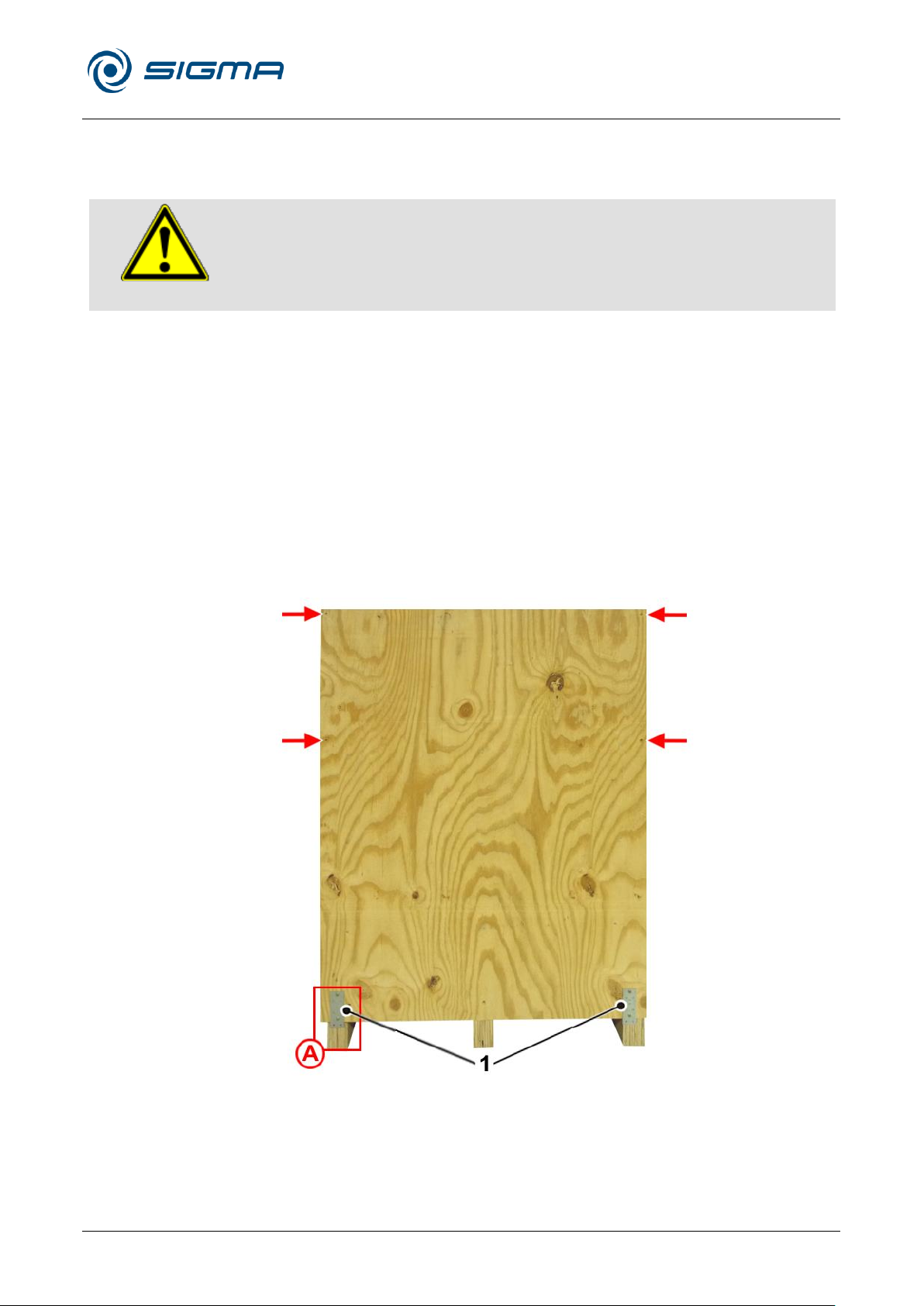
1 Metal fittings
Pos: 92 /100 Sigma/110 BA Zentrifugen Sigma (Projekte)/8KS_8KBS_8KHBS/040 Lagerung und Transport/040-0040 Verpackung - Überschrift @ 29\mod_1 405327385434_68.docx @ 199703 @ 2 @ 1
4.4 Packaging
Pos: 93 /100 Sigma/110 BA Zentrifugen Sigma (Projekte)/8KS_8KBS_8KHBS/040 Lagerung und Transport/040-0042 Verpackung - Text flacher Deckel @ 46\mod_1481610717403_68.docx @ 4617 52 @ @ 1
The centrifuge is packaged in a wooden crate.
• Remove the upper cover.
• Remove the packing material and all of the accessories.
Unloading the centrifuge with a forklift truck
One side panel of the crate has metal fittings (see the following illustration,
detail A).
• Remove the two lower screws of each of the metal fittings and then the
four outer screws in the upper half of the side panel (see the following
illustration). Then, remove the side panel.
Page 30
Refrigerated Centrifuge Sigma 8KS
Refrigerated Centrifuge Sigma 8KBS
4 Storage and transport
30 / 131
Version 08/2012, Rev. 2.5 of 02/07/2018 • sb
Translation of the original operating manual, part no. 0702502
NOTE
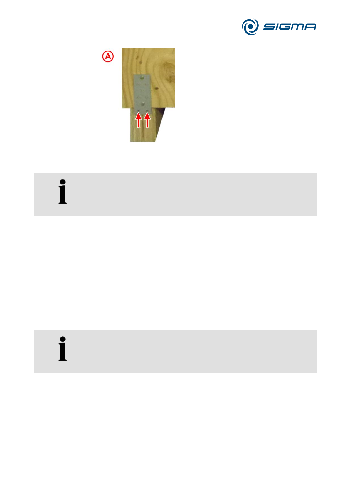
The centrifuge weighs approximately 450 kg!
NOTE
Do not remove the screws in the middle of the side panel. They hold the
substructure of the ramp in place.
Fig. 10: Positions of the screws for removing the side panel
• Lift the centrifuge off the bottom of the crate by way of a forklift truck.
Unloading the centrifuge with a hand pallet jack
If no forklift truck is available, one side panel of the wooden crate can be
used as a ramp so that the centrifuge can be unloaded from the crate by
way of a hand pallet jack (ground clearance 85 mm max.).
One side panel of the crate has metal fittings (see the illustration above,
detail A).
• Remove the two lower screws of the two metal fittings and then the four
outer screws in the upper half of the side panel (see the illustration
above). Then, remove the side panel. The metal fittings remain on the
side panel.
Page 31
Refrigerated Centrifuge Sigma 8KS
Refrigerated Centrifuge Sigma 8KBS
4 Storage and transport
Version 08/2012, Rev. 2.5 of 02/07/2018 • sb
31 / 131
Translation of the original operating manual, part no. 0702502
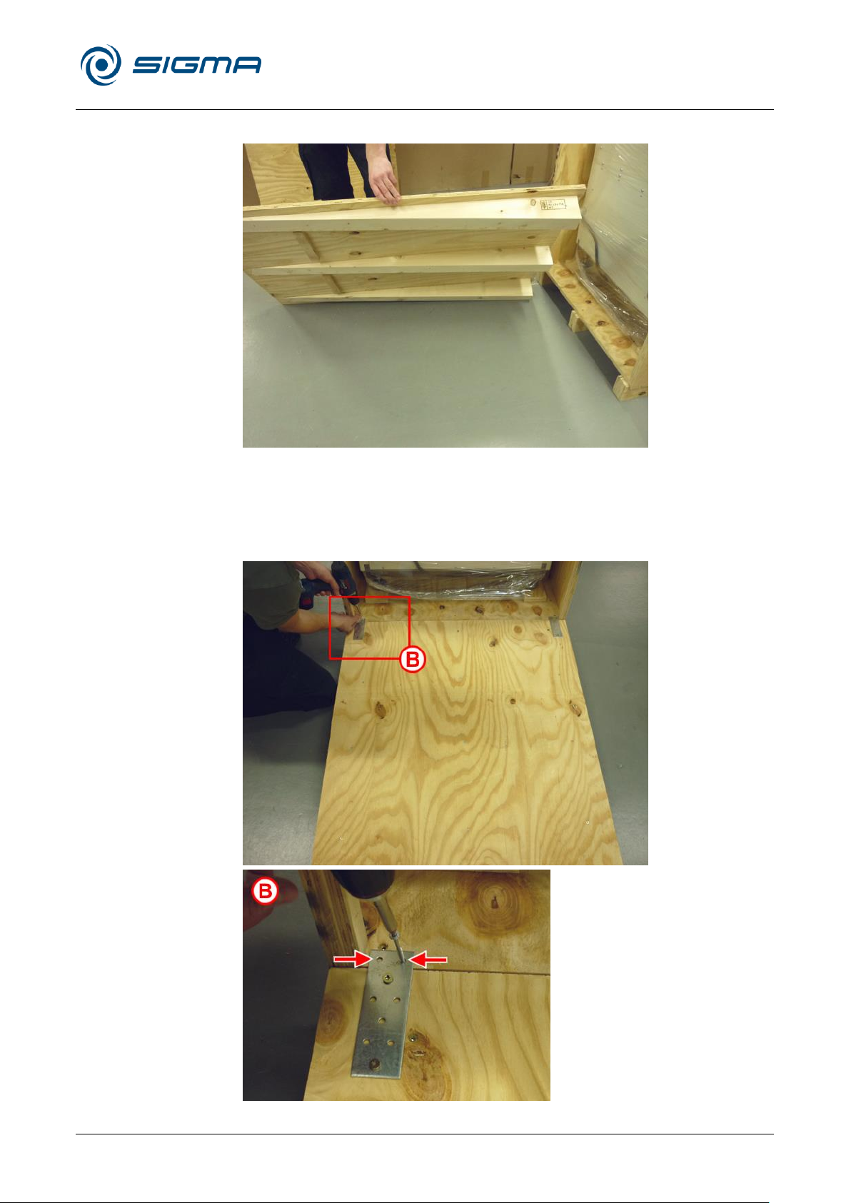
• Position the side panel in front of the bottom of the crate as a ramp.
Fig. 11: Positioning of the ramp
• Secure the ramp on the bottom of the crate by way of the two metal
fittings and the screws that have been removed beforehand (see the
following illustration).
Fig. 12: Positions of the screws for securing the ramp (here: left side)
Page 32

Refrigerated Centrifuge Sigma 8KS
Refrigerated Centrifuge Sigma 8KBS
4 Storage and transport
32 / 131
Version 08/2012, Rev. 2.5 of 02/07/2018 • sb
Translation of the original operating manual, part no. 0702502
CAUTION
Do not unload the centrifuge via the ramp on its castors since, in this case,
the centrifuge would be difficult to steer and could slip off the ramp.
NOTE
Due to its design and dimensions, an electric pallet jack is not suitable for
unloading the centrifuge.
• Move the pallet jack over the ramp and under the centrifuge and lift the
centrifuge off the bottom of the crate.
• Unload the centrifuge carefully via the ramp. While doing so secure the
centrifuge with a sufficient number of persons in order to prevent it from
slipping off to the side.
Unloading the centrifuge with an electric pallet jack
Pos: 94 /010 Universalmodule/Abschnit tswechsel @ 0\mod_1202124514062_0.d ocx @ 418 @ @ 1
Pos: 95 /010 Universalmodule/Seitenwec hsel @ 0\mod_1202116244312_0.doc x @ 105 @ @ 1
• Retain the packaging for any possible future transport of the centrifuge.
Page 33
Refrigerated Centrifuge Sigma 8KS
Refrigerated Centrifuge Sigma 8KBS
5 Set-up and connection
Version 08/2012, Rev. 2.5 of 02/07/2018 • sb
33 / 131
Translation of the original operating manual, part no. 0702502
NOTE
The centrifuge 8KS / SKBS with an air-cooled compressor should not be
set up with its left side against a wall, since otherwise the hot air, which is
emitted out the back, will be drawn in again as fresh air for cooling. As a
result, the unit will switch off due to overheating (see chapter 7.2 - "Table
of error codes").
DANGER
Ensure that the centrifuge is disconnected from the power supply during
the set-up and alignment.
NOTE
Pay attention to the layout plan (see chapter 11.9 - "Layout plan")!
Pos: 96 /100 Sigma/100 BA Zentrifugen Sigma (Standardmodule)/050 Aufstellung und Anschluss/050 Aufstellung und A nschluss=============== =================== @ 27\mod_1405319173 071_68.docx @ 192381 @ 1 @ 1
5 Set-up and connection
Pos: 97 /100 Sigma/110 BA Zentrifugen Sigma (Projekte)/8KS_8KBS_8KHBS/050 Aufstellung und Anschluss/050-0010 Aufstellort 8KS_8KBS @ 29\mod_1 405327400003_68.docx @ 199717 @ 2 @ 1
5.1 Installation site
Pos: 98 /010 Universalmodule/ Leerzeile @ 0\ mod_1202116244500_0.docx @ 11 4 @ @ 1
Pos: 99 /010 Universalmodule/ Leerzeile @ 0\mod_1202116244500_0.docx @ 11 4 @ @ 1
Pos: 100 /100 Sigma/110 BA Zentrifugen Sig ma (Projekte)/8KS_8KBS_8KHBS/05 0 Aufstellung und Anschluss/050-001 1 Aufstellen und Ausrichten der Zentrifug e @ 29\mod_1405327400697_68.d ocx @ 199731 @ 2 @ 1
Operate the centrifuge only in closed and dry rooms.
All the energy supplied to the centrifuge is converted into heat and emitted
to ambient air.
• Air cooled centrifuges: Ensure sufficient ventilation.
• Water cooled centrifuges: Provide sufficient water throughput.
• Do not position the centrifuge near heat generators.
• Avoid direct sunlight (UV radiation).
• During transport from cold to warmer places, condensational water will
collect inside the centrifuge. Allow sufficient time for drying (min. 24 h)
before using the centrifuge again.
5.2 Set-up and alignment of the centrifuge
Pos: 101 /010 Universalmodule/Seiten wechsel @ 0\mod_1202116244312_0.d ocx @ 105 @ @ 1
Page 34
Refrigerated Centrifuge Sigma 8KS
Refrigerated Centrifuge Sigma 8KBS
5 Set-up and connection
34 / 131
Version 08/2012, Rev. 2.5 of 02/07/2018 • sb
Translation of the original operating manual, part no. 0702502
CAUTION
Do not use the lid handle to move the centrifuge because it could break
off!
CAUTION
The castors of the centrifuge are made of steel without any plastic coating.
Damage to the surface of the floor cannot be excluded.
DANGER
For reasons of safety, the centrifuge must not be operated while it is set up
on its castors!
NOTE
The centrifuge must be set-up stably and horizontally at the installation
site.
Pos: 102 /100 Sigma/110 BA Zentrifug en Sigma (Projekte)/8KS_8KBS_8KHBS/ 050 Aufstellung und Anschluss/050-001 1-0010 Aufstellung @ 29\mod_14053 27401538_68.docx @ 199745 @ 3 @ 1
5.2.1 Set-up
• Transport the centrifuge as closely as possible to the installation site
with a lifting device (e.g. forklift).
• Set the centrifuge down.
• To place the centrifuge on the castors, open the front door with the
supplied square spanner (part no. 930 114) by turning it clockwise by
90°. Open the front door to the left in order to access the two locking
screws located at the front.
• Loosen the two hexagon lock nuts with the open spanner, size 24 (part
no. 930 024), and screw in the locking screws with the open spanner,
size 8/10 (part no. 930015), in the anticlockwise direction up to the stop
until the adjustment feet are completely relieved of the load.
• Loosen the lock nuts of the two locking screws on the back from the
side and from below with the open spanner, size 24 (part no. 930 024).
Then, screw in the locking screws anticlockwise with the open spanner,
size 13/14 (part no. 930 013), until the adjustment feet are completely
relieved of the load.
• Transport the centrifuge on the castors to the installation site.
Pos: 103 /010 Universalmodule/ Leerzeile @ 0\mod_1202116244500_0.docx @ 1 14 @ @ 1
Pos: 104 /010 Universalmodule/ Leerzeile @ 0\mod_1202116244500_0.docx @ 1 14 @ @ 1
Pos: 105 /100 Sigma/110 BA Zentrifugen Sig ma (Projekte)/8KS_8KBS_8KHBS/ 050 Aufstellung und Anschluss/050-001 1-0020 Ausrichtung @ 29\mod_1405 327402425_68.docx @ 199759 @ 3 @ 1
5.2.2 Alignment
• Set the centrifuge on its adjustable feet (see chapter 5 - "Set-up and
connection" in reverse order). To do so, turn all of the feet clockwise by
hand until they touch the ground. Then, perform approximately two
more clockwise turns with the open spanner until the castors are
suspended in the air.
Page 35
Refrigerated Centrifuge Sigma 8KS
Refrigerated Centrifuge Sigma 8KBS
5 Set-up and connection
Version 08/2012, Rev. 2.5 of 02/07/2018 • sb
35 / 131
Translation of the original operating manual, part no. 0702502
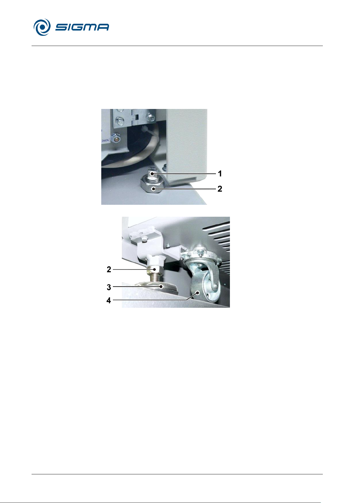
1 Locking screw
2 Lock nut
3 Adjusting foot
4 Castor
• Open the lid with the emergency lid release system. To do so, lift off the
plugs on the left side (e.g. with a screwdriver) and unlock the lid locks
by turning them clockwise with the supplied square spanner (see
chapter 7.1.1 - "Emergency lid release").
• Align the centrifuge with a spirit level in two directions.
• Tighten the four lock nuts and close the front door.
• Plug in the mains power plug.
Pos: 106 /010 Universalmodule/Seiten wechsel @ 0\mod_1202116244312_0.d ocx @ 105 @ @ 1
Fig. 13: Alignment at the front
Fig. 14: Alignment at the back
Page 36
Refrigerated Centrifuge Sigma 8KS
Refrigerated Centrifuge Sigma 8KBS
5 Set-up and connection
36 / 131
Version 08/2012, Rev. 2.5 of 02/07/2018 • sb
Translation of the original operating manual, part no. 0702502
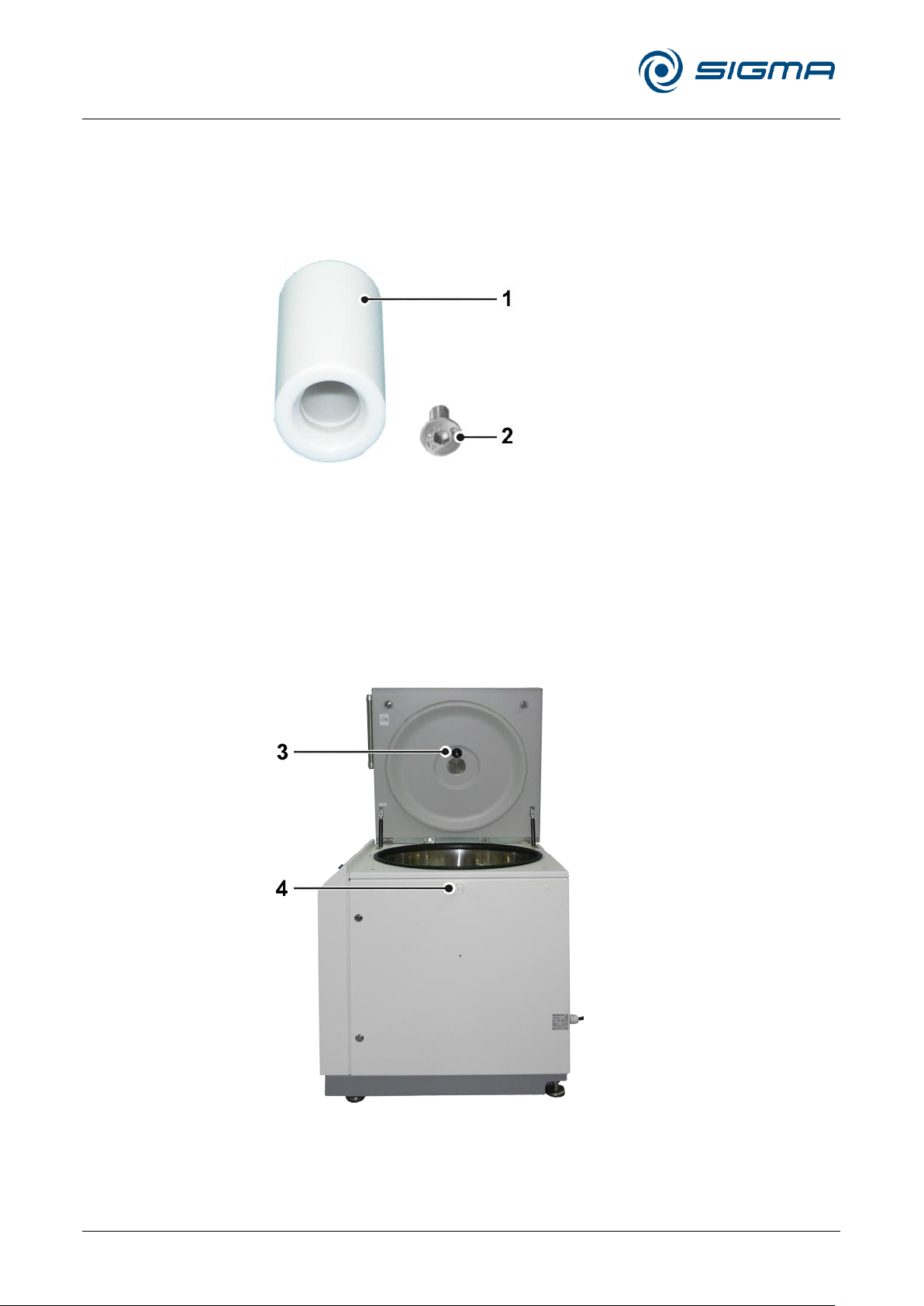
1 Holder for the rotor
cover
2 Hexagon socket head
screw (M6x16)
3 Holder in the
centrifuge lid
4 External holder
Pos: 107 /100 Sigma/110 BA Zentrifugen Sig ma (Projekte)/8KS_8KBS_8KHBS/ 050 Aufstellung und Anschluss/050-001 3 Montage des Deckelhalters - flac her Deckel @ 46\mod_1481537008664_6 8.docx @ 461675 @ 2 @ 1
5.3 Installation of the cover holder
The cover of the swing-out rotor 11805 with a windshield can be placed in
the lid of the centrifuge when loading or unloading the centrifuge. In
addition, it is possible to install a cover holder on the right side of the
centrifuge. The required accessories are included in the scope of supply:
Fig. 15: Cover holder accessories
Installation
There is a hole for the cover holder in the middle of the upper edge on the
right-hand side of the centrifuge.
• Insert the hexagon socket head screw through the hole of the cover
holder and fasten the cover holder to the hole on the right-hand side of
the centrifuge by way of the hexagon socket key (included in the scope
of supply).
Pos: 108 /010 Universalmodule/Seiten wechsel @ 0\mod_1202116244312_0.d ocx @ 105 @ @ 1
Fig. 16: Storage options for the windshield cover
Page 37

Refrigerated Centrifuge Sigma 8KS
Refrigerated Centrifuge Sigma 8KBS
5 Set-up and connection
Version 08/2012, Rev. 2.5 of 02/07/2018 • sb
37 / 131
Translation of the original operating manual, part no. 0702502
DANGER
The operating voltage on the name plate must correspond to the local
supply voltage!
Pos: 109 /100 Sigma/100 BA Zentrifugen Sig ma (Standardmodule)/050 Aufstellu ng und Anschluss/050-0020 Energie versorgung------------------------------------------------------ @ 27\mod_1405319175630_68.docx @ 192409 @ 2 @ 1
5.4 Power supply
Pos: 110 /100 Sigma/100 BA Zentrifugen Sig ma (Standardmodule)/050 Aufstellu ng und Anschluss/050-0020-0013 A nschlussart (Cekon-Stecker 5-polig) @ 3 2\mod_1417599843077_68.docx @ 2 22470 @ 3 @ 1
5.4.1 Type of connection
Pos: 111 /010 Universalmodule/ Leerzeile @ 0\mod_1202116244500_0.docx @ 1 14 @ @ 1
Pos: 112 /100 Sigma/100 BA Zentrifugen Sig ma (Standardmodule)/050 Aufstellu ng und Anschluss/050-0020-0020 Sic herungen bauseits (außer 3-30KS) @ 7\mod_1306312302397_68.docx @ 4351 3 @ 3 @ 1
5.4.2 Customer-provided fuses
Pos: 113 /010 Universalmodule/ Leerzeile @ 0\mod_1202116244500_0.docx @ 1 14 @ @ 1
Pos: 114 /100 Sigma/110 BA Zentrifugen Sig ma (Projekte)/8KS_8KBS_8KHBS/05 0 Aufstellung und Anschluss/050-004 0-0030 Trennvorrichtung @ 29\mod_1 405327407717_68.docx @ 199801 @ 3 @ 1
SIGMA laboratory centrifuges are units of protection class I. The
centrifuges of this type have a five-wire power cord (2.5 m) with a 5channel Cekon-plug (16 A). Behind the front door there are three fuses with
a rocker switch.
Typically, the centrifuge must be protected with 16 Amp L or B fuses that
are to be provided by the customer.
5.4.3 Power isolating device
The electrical installation of the building must include a power isolating
device in the form of a switch or circuit breaker. This device must be
located near the centrifuge. Furthermore, it must be easily accessible for
Pos: 115 /010 Universalmodule/Seiten wechsel @ 0\mod_1202116244312_0.d ocx @ 105 @ @ 1
the operator and marked as the power isolating device for the centrifuge.
Page 38
Refrigerated Centrifuge Sigma 8KS
Refrigerated Centrifuge Sigma 8KBS
5 Set-up and connection
38 / 131
Version 08/2012, Rev. 2.5 of 02/07/2018 • sb
Translation of the original operating manual, part no. 0702502
WARNING
• Do not open the condensate drain unless the rotor is at a complete
standstill.
NOTE
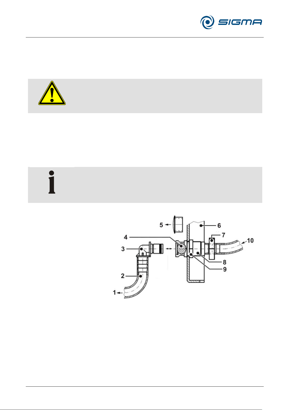
At the installation site, the condensate drain can be laid to the outside (see
figure).
1 Drain outside of the centrifuge
2 Hose (part no. 80415)
3 Hose connector (unblocks the
drain when connected)
4 Unlocking button
5 Plug (to be removed prior to the
installation)
6 Centrifuge door (front, left side)
7 Clamp
8 Quick coupling
9 Lock nut (fasten by hand)
10 Condensate – rotor chamber
Pos: 116 /100 Sigma/110 BA Zentrifugen Sig ma (Projekte)/8KS_8KBS_8KHBS/05 0 Aufstellung und Anschluss/050-005 0 Kondensatablauf @ 29\mod_14053 27408547_68.docx @ 199815 @ 2 @ 1
5.5 Condensate drain
The condensate drain is used to drain the condensate off that forms in the
rotor chamber during the centrifugation. It consists of a hose with a plastic
valve. This hose runs from the rotor chamber to a point on the left behind
the front door of the centrifuge.
Draining the condensate off
• Unplug the mains power plug.
• Open the front door with the supplied square spanner (order no. 930
114).
• Connect the supplied hose connector and drain the condensate.
• Disconnect the hose connector by pressing the unlocking button.
Pos: 117 /010 Universalmodule/Seiten wechsel @ 0\mod_1202116244312_0.d ocx @ 105 @ @ 1
Fig. 17 Laying the condensate drain to the outside
Page 39
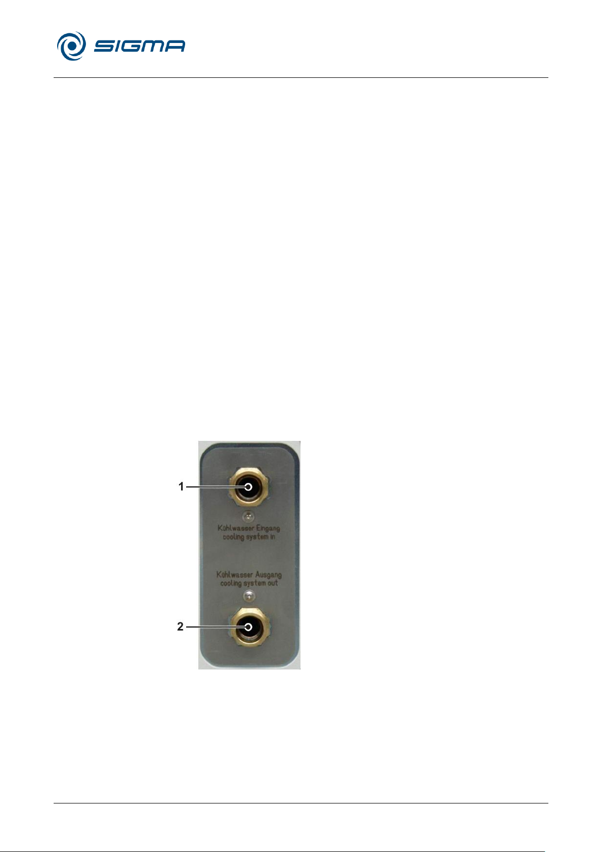
Refrigerated Centrifuge Sigma 8KS
Refrigerated Centrifuge Sigma 8KBS
5 Set-up and connection
Version 08/2012, Rev. 2.5 of 02/07/2018 • sb
39 / 131
Translation of the original operating manual, part no. 0702502
1 Connector for the
cooling water inlet
2 Connector for the
cooling water outlet
Pos: 118 /100 Sigma/110 BA Zentrifugen Sig ma (Projekte)/8KS_8KBS_8KHBS/05 0 Aufstellung und Anschluss/050-006 0 Sonderausstattung: Wasserkühlung @ 29\mod_1405327409399_68.docx @ 199829 @ 2 @ 1
5.6 Special equipment: water cooling system
Centrifuges with water cooling are equipped with a special refrigeration unit
with a refrigerant (CFC-free), modified electronic system, and a special
software version. The housing of the GMP version is completely closed. All
of the other units have vent slots for the motor and electronic power
system.
Operating conditions
• The centrifuge must only be operated with media-neutral water of
drinking water quality (hardness <8) or with another suitable refrigerant.
We recommend using a filter (to be provided by the customer).
• The operating pressure of the water must be between 1.5 and 5 bar.
We recommend using a pressure reducer (to be provided by the
customer).
• The maximum flow rate depends on the operating conditions (e.g.
speed and rotor temperature). The minimum cooling water consumption
at maximum power is approximately 5 l/min.
At a standstill, the water supply is stopped by a solenoid valve. In the
case of the GMP version, the valve is opened in two steps:
1. reduced flow, only for the internal air cooler
2. unlimited flow, when the compressors are running.
• The maximum temperature at the water inlet is 20°C. The lower the
water temperature, the more efficient the cooling.
• The centrifuge is equipped with a ¾-inch water connector .
Pos: 119 /010 Universalmodule/Abschnitt swechsel @ 0\mod_1202124514062_0. docx @ 418 @ @ 1
Pos: 120 /010 Universalmodule/Seiten wechsel @ 0\mod_1202116244312_0.d ocx @ 105 @ @ 1
Fig. 18: Connections for the water cooling system
Page 40
Refrigerated Centrifuge Sigma 8KS
Refrigerated Centrifuge Sigma 8KBS
6 Using the centrifuge
40 / 131
Version 08/2012, Rev. 2.5 of 02/07/2018 • sb
Translation of the original operating manual, part no. 0702502
DANGER
• Before the initial start-up, please ensure that your centrifuge is properly
set up and installed (see chapter 5 - "Set-up and connection").
WARNING
Do not place your fingers between the lid and the housing when closing
the lid. Risk of crushing!
Pos: 121 /100 Sigma/100 BA Zentrifugen Sig ma (Standardmodule)/060 Betrieb_ Spincontrol L+S/060 Betrieb====== ============================ ======= @ 27\mod_1405319198895_68.do cx @ 192423 @ 1 @ 1
6 Using the centrifuge
Pos: 122 /100 Sigma/100 BA Zentrifugen Sig ma (Standardmodule)/060 Betrieb_ Spincontrol L+S/060-0010 Erste Inb etriebnahme @ 27\mod_1405319200130 _68.docx @ 192437 @ 2 @ 1
6.1 Initial start-up
Pos: 123 /010 Universalmodule/ Leerzeile @ 0\mod_1202116244500_0.docx @ 1 14 @ @ 1
Pos: 124 /010 Universalmodule/ Leerzeile @ 0\mod_1202116244500_0.docx @ 1 14 @ @ 1
Pos: 125 /100 Sigma/100 BA Zentrifugen Sig ma (Standardmodule)/060 Betrieb_ Spincontrol L+S/060-0020 Einschalte n (außer 6-16HS) @ 27\mod_14053192 01340_68.docx @ 192451 @ 2 @ 1
6.2 Switching the centrifuge on
• Press the mains power switch.
Pos: 126 /010 Universalmodule/ Leerzeile @ 0\mod_1202116244500_0.docx @ 1 14 @ @ 1
Pos: 127 /100 Sigma/100 BA Zentrifugen Sig ma (Standardmodule)/060 Betrieb_ Spincontrol L+S/060-0020-0010 Öff nen und Schließen des Deckels - 2 Schlö sser @ 27\mod_1405319203737_68.do cx @ 192479 @ 3 @ 1
6.2.1 Opening and closing the lid
The display then illuminates. The centrifuge is ready for operation.
The lid can be opened if the centrifuge is at a standstill and if the lid key is
illuminated.
• Press the lid key in order to open the lid.
The centrifuge cannot be started if the lid is opened.
• To close, press with both hands slightly on the lid until both locks are
audibly locked.
Pos: 128 /010 Universalmodule/Seiten wechsel @ 0\mod_1202116244312_0.d ocx @ 105 @ @ 1
Page 41
Refrigerated Centrifuge Sigma 8KS
Refrigerated Centrifuge Sigma 8KBS
6 Using the centrifuge
Version 08/2012, Rev. 2.5 of 02/07/2018 • sb
41 / 131
Translation of the original operating manual, part no. 0702502
WARNING
All swing-out rotors applicable for this centrifuge and the angle rotor 12510
weigh more than 18 kg.
• Always lift the rotors with a lifting device or with a sufficient number of
people helping you.
WARNING
After frequent use, the rotor tie-down screw must be loosened by some
turns, the rotor has to be lifted and fastened again. This must be done
once a day or after 20 cycles. This ensures a proper connection between
the rotor and the motor shaft.
NOTE
• Slightly grease the rotor and lid seals after cleaning.
WARNING
The lid screw serves for the fastening of the lid onto the rotor only, not for
the fastening of the rotor onto the motor shaft!
Pos: 129 /100 Sigma/110 BA Zentrifugen Sig ma (Projekte)/8KS_8KBS_8KHBS/06 0 Betrieb/060-0020-0020 Einsetz en von Rotoren und Zubehör 8KS_8KBS_ 8KHBS @ 29\mod_1405327449337_ 68.docx @ 199843 @ 3 @ 1
6.2.2 Installation of rotors and accessories
Pos: 130 /010 Universalmodule/ Leerzeile @ 0\mod_1202116244500_0.docx @ 1 14 @ @ 1
Pos: 131 /100 Sigma/110 BA Zentrifugen Sig ma (Projekte)/8KS_8KBS_8KHBS/ 060 Betrieb/060-0020-0020-0010 Eins etzen eines Rotors @ 29\mod_140532 7450012_68.docx @ 199857 @ 4 @ 1
6.2.2.1 Installation of a rotor
• Open the centrifuge lid by pressing the lid key.
• Unscrew the rotor tie-down screw from the motor shaft (counter-
clockwise).
• Lower the rotor with its central bore straight down onto the motor shaft.
• Turn the adapter end of the motor shaft anti-clockwise with the supplied
hexagon socket key (part no. 930 050) and tighten the internal thread of
the rotor with 20 Nm with the rotor wrench (size 17/19, part no. 930 018).
• Follow the safety instructions and hazard warnings (see chapter 3 -
Pos: 132 /010 Universalmodule/ Leerzeile @ 0\mod_1202116244500_0.docx @ 1 14 @ @ 1
Pos: 133 /100 Sigma/110 BA Zentrifugen Sig ma (Projekte)/8KS_8KBS_8KHBS/06 0 Betrieb/060-0020-0020-0020 Eins etzen eines Winkelrotors mit Hermetikd eckel @ 29\mod_1405327450800_68.d ocx @ 199871 @ 4 @ 1
"Safety")!
6.2.2.2 Installation of an angle rotor with a hermetic lid
• Lower the rotor onto the motor shaft.
• Turn the adapter end of the motor shaft anti-clockwise with the supplied
hexagon socket key (part no. 930 050) and tighten the internal thread of
the rotor with 20 Nm with the rotor wrench (size 17/19, part no. 930 018).
• Screw the rotor cover onto the rotor and tighten it with the supplied tool
no. 17985 by hand.
• The rotors can be installed or removed with a closed lid after loosening
the rotor tie-down screw.
• Follow the safety instructions and hazard warnings (see chapter 3 "Safety")!
Pos: 134 /010 Universalmodule/Seiten wechsel @ 0\mod_1202116244312_0.d ocx @ 105 @ @ 1
Page 42
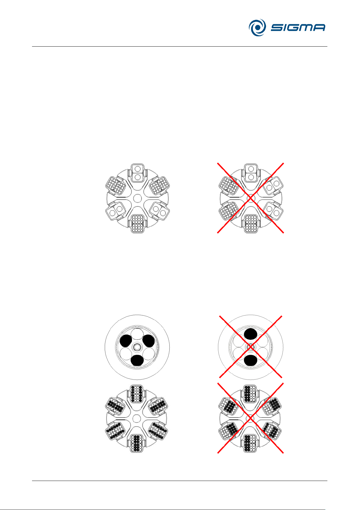
Refrigerated Centrifuge Sigma 8KS
Refrigerated Centrifuge Sigma 8KBS
6 Using the centrifuge
42 / 131
Version 08/2012, Rev. 2.5 of 02/07/2018 • sb
Translation of the original operating manual, part no. 0702502
correct
incorrect
correct
incorrect
Pos: 135 /100 Sigma/100 BA Zentrifugen Sig ma (Standardmodule)/060 Betrieb_ Spincontrol L+S/060-0020-0020-0033 Einsetzen von Zubehör 6plätzig 8KS @ 27\mod_1405319209092_68.docx @ 1 92549 @ 4 @ 1
6.2.2.3 Installation of accessories
• Only use vessels that are suitable for the rotor.
• In the case of swing-out rotors, all of the compartments must be
equipped with buckets.
• Always load rotationally symmetrical compartments of the rotors with
the same accessories and fill to avoid imbalance.
Centrifugation with vessels of various sizes
Working with vessel of various sizes is possible. In this case, however, it is
very important that the rotationally symmetrical inserts are identical.
Fig. 19: Permissible and impermissible loading of a swing-out rotor with vessels of various
sizes (example illustration)
Centrifugation with low capacity
• Install the sample vessels in a rotationally symmetrical manner so that
the buckets and their suspensions are loaded evenly.
• It is not permissible to load angle rotors on only one axis.
Pos: 136 /010 Universalmodule/Seite nwechsel @ 0\mod_1202116244312_0.d ocx @ 105 @ @ 1
Fig. 20: Permissible and impermissible loading of an angle rotor and a swing-out rotor
(example illustration)
Page 43
Refrigerated Centrifuge Sigma 8KS
Refrigerated Centrifuge Sigma 8KBS
6 Using the centrifuge
Version 08/2012, Rev. 2.5 of 02/07/2018 • sb
43 / 131
Translation of the original operating manual, part no. 0702502
NOTE
When using glass vessels, the maximum value of 4,000 x g must not be
exceeded (except special high-strength glass tubes; please refer to the
information provided by the manufacturer).
NOTE
When installing the 500 ml bottles use the supplied supporting rings.
CAUTION
At speeds above 8,000 rpm, there is an increased risk of breakage, in
particular for 250 and 500 ml bottles!
Pos: 137 /100 Sigma/100 BA Zentrifugen Sig ma (Standardmodule)/060 Betrieb_ Spincontrol L+S/060-0020-0020-0040 Adapter - nur L+S @ 27\mod_14053 19210191_68.docx @ 192563 @ 4 @ 1
6.2.2.4 Adapters
Pos: 138 /010 Universalmodule/ Leerzeile @ 0\mod_1202116244500_0.docx @ 1 14 @ @ 1
Pos: 139 /100 Sigma/110 BA Zentrifugen Sig ma (Projekte)/8KS_8KBS_8KHBS/06 0 Betrieb/060-0020-0020-0050 Gef äße (nur 8KS/8KBS) @ 48\mod_14870 66087182_68.docx @ 490940 @ 4 @ 1
6.2.2.5 Vessels
In order to ensure easy handling, even if vessels of various sizes are used,
carrier systems were developed.
• Load the opposite adapters with the same number of vessels and with
the same weights in order to avoid imbalance.
• If all of the compartments of a carrier are not used, the buckets must be
loaded evenly. Loading the edges of a bucket only is not permissible.
• Load the tubes outside of the centrifuge. Liquids in the buckets or
multiple carriers cause corrosion.
• Fill the vessels carefully and arrange them according to their weight.
Imbalances result in the excessive wear of the bearings.
• Always fill the tubes up to their useful volume (= the volume that is
stated for the tube).
• Follow the safety instructions and hazard warnings (see chapter 3 "Safety")!
Maximum speed for tubes
Some tubes, such as centrifuge glass tubes, microtubes, culture tubes,
fluoropolymer tubes and especially high-volume tubes can be used in our
rotors, buckets, and adapters at higher speeds than their breaking limit.
Pos: 140 /010 Universalmodule/Seiten wechsel @ 0\mod_1202116244312_0.d ocx @ 105 @ @ 1
Page 44
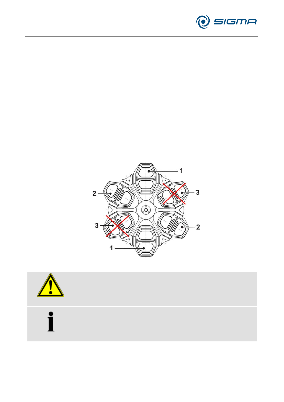
Refrigerated Centrifuge Sigma 8KS
Refrigerated Centrifuge Sigma 8KBS
6 Using the centrifuge
44 / 131
Version 08/2012, Rev. 2.5 of 02/07/2018 • sb
Translation of the original operating manual, part no. 0702502
1 Proper loading
2 Possible loading
3 Improper loading
WARNING
The service life of the adapter for blood bags no. 13867 is limited. Refer to
the table of rotors and accessories with a different service life (see chapter
11.4 - " Table of the service life of rotors and accessories ")!
NOTE
At maximum speed, the plastic adapter 13867 must not be used at a
temperature above 25°C. If it is used at a considerably lower speed (up to
2,500 rpm), the temperature can be higher than 25°C.
Pos: 141 /100 Sigma/110 BA Zentrifugen Sig ma (Projekte)/8KS_8KBS_8KHBS/ 060 Betrieb/060-0020-0020-0060 Blut beutelsysteme @ 29\mod_1405327451 565_68.docx @ 199885 @ 4 @ 1
6.2.2.6 Blood bag systems
• All six places on the rotor must be loaded with buckets.
• It is required to fill just two opposite buckets must be filled with one
adapter for blood bags and two blood bag systems each.
• The opposite buckets, including the filled blood bag systems, must have
an equal weight. If the number of blood bags is uneven, a balance
adapter must be used. For taring, several balance weights are
available.
• The blood bags must be put into opposite buckets in a mirror-inverted
way (see figure).
• In both adapter compartments, the main blood bag must be situated
towards the middle. The opposite bucket must be loaded
correspondingly (see figure, item 1).
• When using smaller bag systems or in the case of incompletely filled
blood bags, adapters (e.g. part no. 17750) must be inserted together
with the blood bag systems. This will help to avoid any slipping of the
bags, which could result in an imbalance.
Fig. 21: Loading of blood bag systems
Pos: 142 /010 Universalmodule/Seiten wechsel @ 0\mod_1202116244312_0.d ocx @ 105 @ @ 1
Page 45
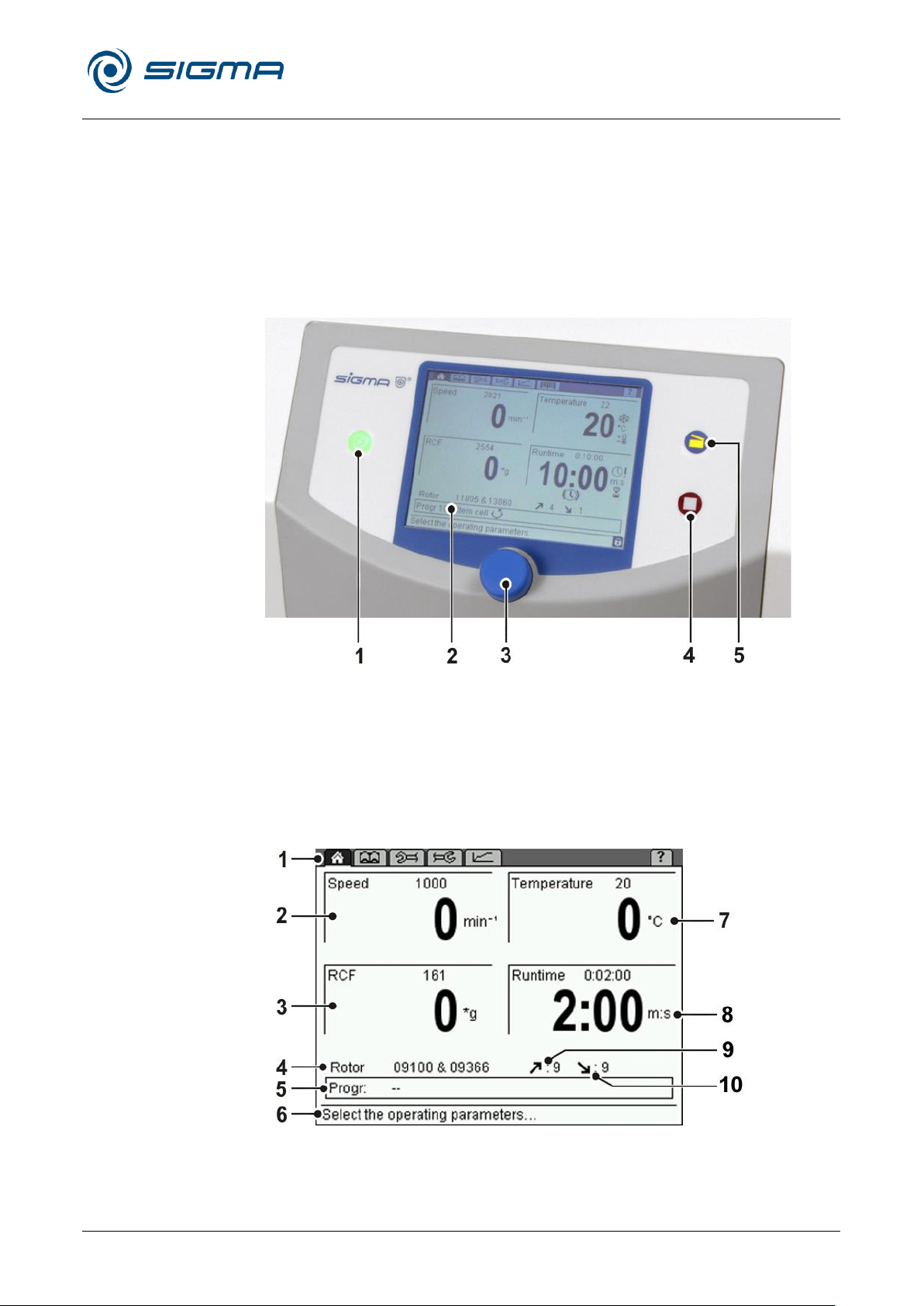
Refrigerated Centrifuge Sigma 8KS
Refrigerated Centrifuge Sigma 8KBS
6 Using the centrifuge
Version 08/2012, Rev. 2.5 of 02/07/2018 • sb
45 / 131
Translation of the original operating manual, part no. 0702502
1 Start button
2 Display
3 Function knob
4 Stop button
5 Lid button
1 Menu bar
2 Speed field
3 RCF field
4 Rotor field
5 Program field
6 Status bar
7 Temperature field
8 Time field
9 Acceleration curve
10 Deceleration curve
Pos: 143 /100 Sigma/100 BA Zentrifugen Sig ma (Standardmodule)/060 Betrieb_ Spincontrol L+S/Spincontrol S (Zent7)/060- 0030 Spincontrol S Steuerung---------------------------------------------- @ 27\mod_1405320192364_68.docx @ 193109 @ 2 @ 1
6.3 Control system "Spincontrol S"
Pos: 144 /100 Sigma/100 BA Zentrifugen Sig ma (Standardmodule)/060 Betrieb _Spincontrol L+S/Spincontrol S (Zent7)/0 60-0030-0010 Bedienoberfläche mit Te mperaturanzeige @ 27\mod_1405 320193718_68.docx @ 193123 @ 3 @ 1
6.3.1 User interface
The centrifuge is operated via three buttons with integrated light-emitting
diodes and one function knob. The display is divided into several different
fields. The various functions of the system can be called up by pressing
and turning the function knob.
Pos: 145 /010 Universalmodule/Seiten wechsel @ 0\mod_1202116244312_0.d ocx @ 105 @ @ 1
Fig. 22: User interface of the Spincontrol S control system
Display
The centrifuge display has the following fields:
Fig. 23: Display of the Spincontrol S control system
Page 46

Refrigerated Centrifuge Sigma 8KS
Refrigerated Centrifuge Sigma 8KBS
6 Using the centrifuge
46 / 131
Version 08/2012, Rev. 2.5 of 02/07/2018 • sb
Translation of the original operating manual, part no. 0702502
NOTE
A quick stop can be performed even if the centrifuge is blocked against
unauthorised use.
Pos: 146 /100 Sigma/100 BA Zentrifugen Sig ma (Standardmodule)/060 Betrieb_ Spincontrol L+S/Spincontrol S (Zent7)/060- 0030-0020 Manueller Betrieb @ 2 7\mod_1405320198028_68.docx @ 19 3151 @ 3 @ 1
6.3.2 Manual mode
Pos: 147 /100 Sigma/100 BA Zentrifugen Sig ma (Standardmodule)/060 Betrieb_ Spincontrol L+S/Spincontrol S (Zent7)/060- 0030-0020-0010 Starten einer Ze ntrifugation @ 27\mod_1405320199237 _68.docx @ 193165 @ 4 @ 1
6.3.2.1 Starting a centrifugation run
Pos: 148 /010 Universalmodule/ Leerzeile @ 0\mod_1202116244500_0.docx @ 1 14 @ @ 1
Pos: 149 /100 Sigma/100 BA Zentrifugen Sig ma (Standardmodule)/060 Betrieb_ Spincontrol L+S/Spincontrol S (Zent7)/060- 0030-0020-0020 Unterbrechen ein er Zentrifugation @ 27\mod_1405320 200374_68.docx @ 193179 @ 4 @ 1
6.3.2.2 Interrupting a centrifugation run
The centrifuge is ready for operation when the start key is illuminated.
• Press the start key in order to start a centrifugation run.
• Press the stop key in order to interrupt a centrifugation run. The
centrifugation run will be terminated prematurely.
Quick stop
• Press the stop key for more than three seconds.
The centrifuge decelerates with the maximum deceleration curve.
After a quick stop, the centrifuge lid must be opened before a new
centrifugation run can be started.
A quick stop can also be triggered during a normal deceleration, e.g. in
order to speed up the deceleration.
When a quick stop is triggered, ―Quick stop‖ will be displayed in the speed
field.
Pos: 150 /010 Universalmodule/ Leerzeile @ 0\mod_1202116244500_0.docx @ 1 14 @ @ 1
Pos: 151 /100 Sigma/100 BA Zentrifugen Sig ma (Standardmodule)/060 Betrieb_ Spincontrol L+S/Spincontrol S (Zent7)/060- 0030-0020-0030 Unterbrechen ein es Bremsvorgangs @ 27\mod_140532 0201742_68.docx @ 193193 @ 4 @ 1
6.3.2.3 Interrupting a deceleration process
• Press the start key during a deceleration process in order to interrupt it
Pos: 152 /010 Universalmodule/ Leerzeile @ 0\mod_1202116244500_0.docx @ 1 14 @ @ 1
Pos: 153 /100 Sigma/100 BA Zentrifugen Sig ma (Standardmodule)/060 Betrieb_ Spincontrol L+S/Spincontrol S (Zent7)/ 060-0030-0020-0040 Auswahl, Anzeig e und Änderung von Daten @ 27\mod_ 1405320202914_68.docx @ 193207 @ 4 @ 1
and to restart the centrifuge.
6.3.2.4 Selection, display, and modification of data
The "Standard" menu is displayed.
• Turn the function knob in order to select a field. The selected field is
inverted.
• Press the function knob. The display starts to flash and the modification
mode is active.
• Turn the function knob in order to modify the set value of the selected
field.
• Press the function knob again to confirm the entry and to quit the
Pos: 154 /010 Universalmodule/Seiten wechsel @ 0\mod_1202116244312_0.d ocx @ 105 @ @ 1
modification mode.
Page 47
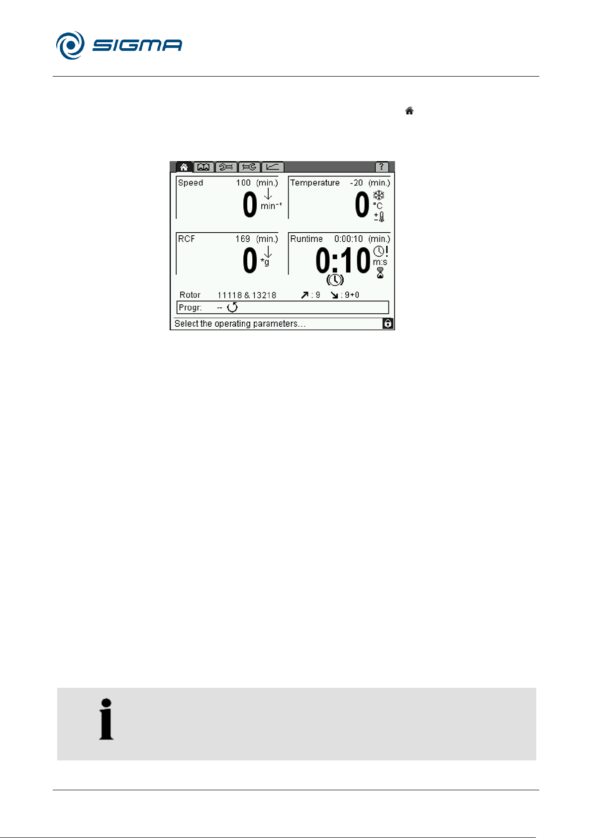
Refrigerated Centrifuge Sigma 8KS
Refrigerated Centrifuge Sigma 8KBS
6 Using the centrifuge
Version 08/2012, Rev. 2.5 of 02/07/2018 • sb
47 / 131
Translation of the original operating manual, part no. 0702502
NOTE
The centrifuge is not equipped with an active heater. As a result,
temperatures above room temperature depend on the air friction of the
running motor.
Pos: 155 /100 Sigma/100 BA Zentrifugen Sig ma (Standardmodule)/060 Betrieb _Spincontrol L+S/Spincontrol S (Zent7)/0 60-0030-0020-0050 Menü Standard - nur KS @ 27\mod_1405320204084_6 8.docx @ 193221 @ 4 @ 1
6.3.2.5 Standard menu
The "Standard" menu is symbolised by the icon " " on the menu bar and it
is displayed a few seconds after the centrifuge has been switched on. In
this menu, the parameters of a centrifugation run can be displayed and
modified.
Fig. 24: Standard menu; here shown with all of the possible symbols
Speed
In the upper section of the field, the set speed of the centrifuge is displayed.
The actual speed is displayed below this value. The values are stated in
revolutions per minute (min-1 = rpm) and depend on the RCF values (see
chapter 2.2.2.1 - "Speed, radius, and relative centrifugal force"). The
maximum speed values depend on the rotor that is used.
Relative centrifugal force (RCF)
The relative centrifugal force is the acceleration that the sample is
subjected to during the centrifugation run. The set value of this parameter is
displayed in the upper section of this field, with the actual value shown
below. The values are stated in g (gravitational acceleration) and they
depend on the speed values (see chapter 2.2.2.1 - "Speed, radius, and
relative centrifugal force"). The maximum RCF values depend on the rotor
that is used.
Temperature
The set temperature is displayed in the upper section of the field, with the
current sample temperature shown below. Temperatures between
-20 °C and +40 °C can be preselected.
Page 48
Refrigerated Centrifuge Sigma 8KS
Refrigerated Centrifuge Sigma 8KBS
6 Using the centrifuge
48 / 131
Version 08/2012, Rev. 2.5 of 02/07/2018 • sb
Translation of the original operating manual, part no. 0702502
NOTE
The parameters speed, RCF, temperature, and runtime can be changed
during the centrifugation.
NOTE
If the centrifuge ist locked with level 02 or higher, it is not possible to start
a short run.
Runtime
The set runtime is displayed in the upper section of this field, with the
remaining runtime shown below. The runtime is defined as the period from
the start of the centrifuge to the beginning of the deceleration phase. The
maximum value is 99 h 59 min 59 sec.
In the "Setup" menu , it can be specified that the runtime is not to be
started until the set speed is reached (see chapter 6.3.2.8 - "Setup menu").
In this case, the symbol "!" appears in the runtime field.
Continuous run
During the continuous run, the runtime of the centrifuge is unlimited and
must be stopped manually. The centrifuge accelerates during the
continuous run until the set speed is reached.
• Select the field "Runtime" and confirm the selection. The display flashes
when it is activated.
• Turn the function knob from the time 0:00:10 anti-clockwise or from the
time 99:59:59 clockwise. "Infinite" will be displayed. After the start of the
centrifuge, the elapsed time will be displayed.
• Deactivate the continuous run by pressing the stop button or by entering
a specific runtime.
Short run
A short run can be started if no run is active.
• Keep the start button pressed during the short run.
During the short run, the centrifuge accelerates with acceleration curve 9
(maximum acceleration) until the maximum speed of the rotor is reached.
The runtime is counted and in the speed field the message "Short run"
flashes.
When the start button is released, the centrifuge decelerates with the
maximum deceleration curve to a standstill.
Page 49
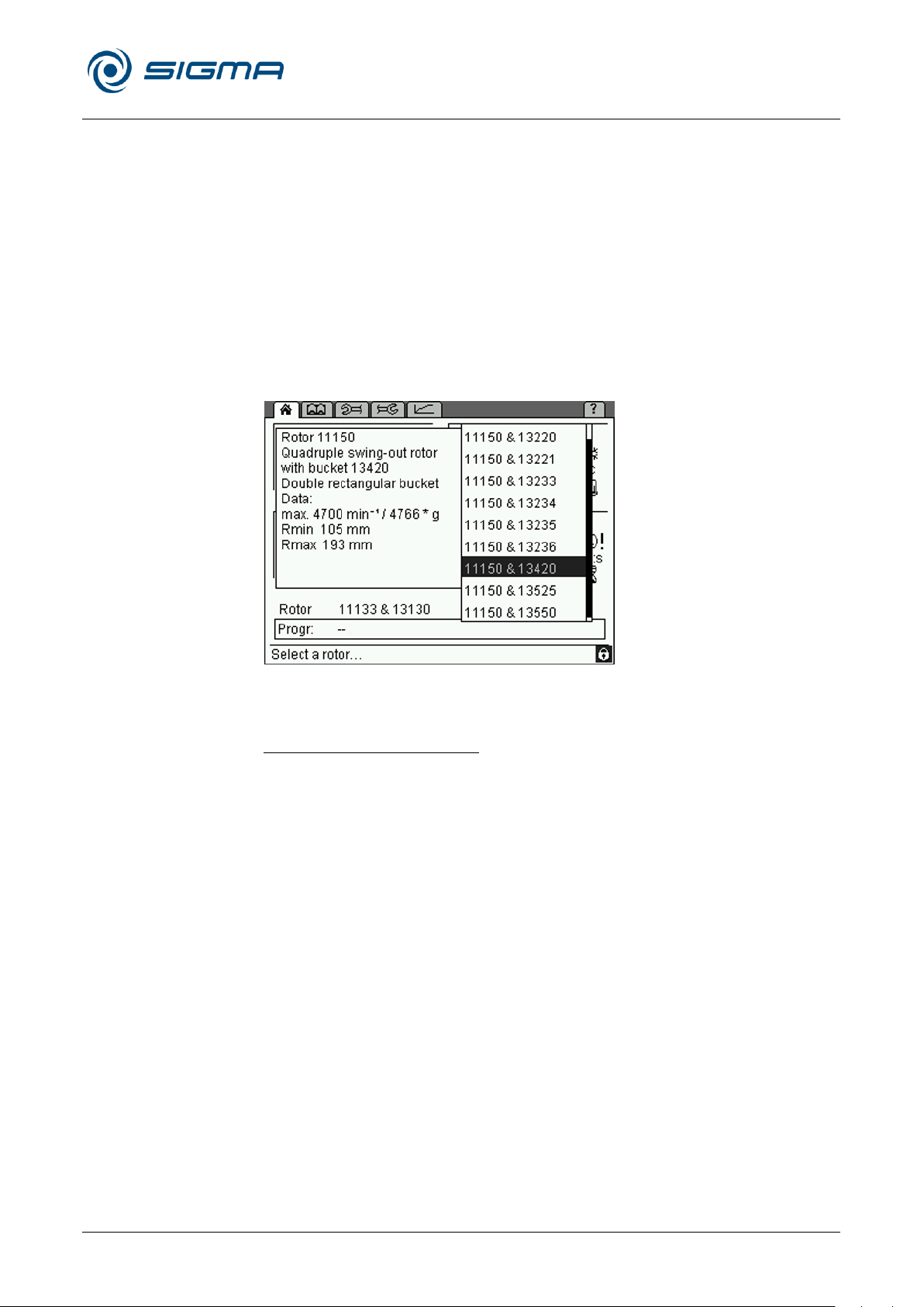
Refrigerated Centrifuge Sigma 8KS
Refrigerated Centrifuge Sigma 8KBS
6 Using the centrifuge
Version 08/2012, Rev. 2.5 of 02/07/2018 • sb
49 / 131
Translation of the original operating manual, part no. 0702502
Rotor: rotor selection list
This field shows the rotor that is currently being used.
• Select the field "Rotor" and confirm the selection. A list with all of the
possible rotors without buckets is displayed.
• Select the desired rotor.
– If an angle rotor is selected, additional information concerning this
rotor will be displayed.
– In the case of swing-out rotors, a list with all of the possible
rotor/bucket combinations will be displayed. Select an item from the
list so that the additional information concerning the combination will
be displayed.
• Press the function knob in order to accept the data.
Fig. 25: Rotor selection list, here with potential rotor-bucket combinations
and additional information
Automatic rotor identification
The centrifuge automatically identifies the rotor that is currently being used.
• If the system identifies a different rotor than the one that is set and if
there are no different buckets for this rotor, the rotor input will be
adapted automatically. The system will not display a message.
• If the system identifies a different rotor than the one that is set, and if
there are different rotor/bucket combinations for this rotor, the system
will automatically identify the correct rotor and select the rotor/bucket
combination with the lowest speed. The system will display a
corresponding message so that the combination can be adapted
manually.
• If the system cannot identify the rotor, a message will be displayed. The
rotor cannot be used in the centrifuge.
This prevents the maximum permissible speed from being exceeded.
Page 50
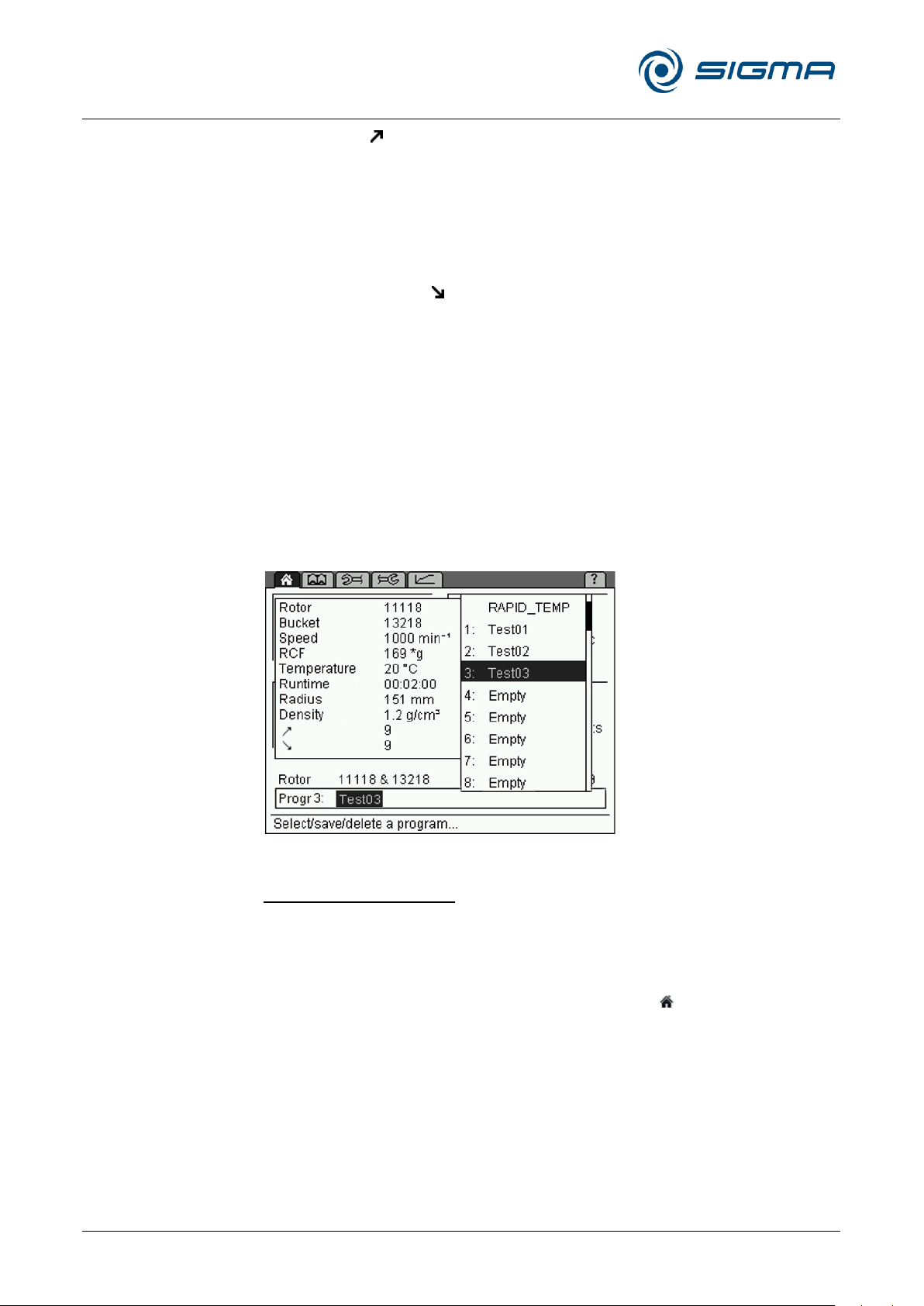
Refrigerated Centrifuge Sigma 8KS
Refrigerated Centrifuge Sigma 8KBS
6 Using the centrifuge
50 / 131
Version 08/2012, Rev. 2.5 of 02/07/2018 • sb
Translation of the original operating manual, part no. 0702502
Acceleration
This function is used to select an acceleration curve. One can select a
linear rise (curves 0-9) or a quadratic rise (curves 10-19). The acceleration
curves 20-29 can be programmed as desired (see chapter 11.3 "Acceleration and deceleration curves").
Deceleration (brake)
This function is used to select a curve that decelerates the centrifuge to a
standstill. Deceleration curves are inverted images of the acceleration
curves and are labelled with identical numbers. Deceleration curve no. 0
represents a brakeless deceleration.
Progr.: program list
This field in the "Standard" menu shows the program that is currently
loaded. When the field is selected, the program list is displayed (for
information on how to work with the programs, please see chapter 6.3.3 "Program mode").
The program "RAPID_TEMP" (see below) cannot be deleted.
Fig. 26: Program list
Program "RAPID_TEMP"
Precooling or preheating at a standstill may distort the measurement results
and cause the increased wear of the mechanical components. This is why
the centrifuge has a special program that precools or preheats the rotor
chamber rapidly to a preset value under defined conditions.
• Select the option "Progr" in the "Standard" menu and confirm the
selection. The program list will be displayed.
• Select the program "RAPID_TEMP" on the program list and confirm the
selection. The display shows ⅓ of the maximum rotor speed and the
corresponding RCF value. The deceleration (brake) and acceleration
curves correspond to curve 9 and the runtime field indicates "infinite"
(continuous run).
Page 51
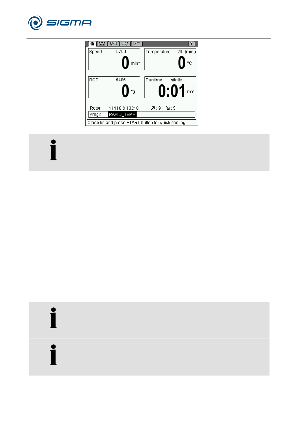
Refrigerated Centrifuge Sigma 8KS
Refrigerated Centrifuge Sigma 8KBS
6 Using the centrifuge
Version 08/2012, Rev. 2.5 of 02/07/2018 • sb
51 / 131
Translation of the original operating manual, part no. 0702502
NOTE
The program will only be loaded if the actual temperature is above the set
temperature.
NOTE
The automatic lid opening function is suppressed after a rapid cooling run
in order to prevent the system from reheating.
NOTE
The delta T temperature monitoring system (see chapter 6.3.2.7 "Parameters menu", Process) remains inactive as long as the
"RAPID_TEMP" program is active.
Fig. 27: Program "RAPID_TEMP"
• Press the start button in order to start the rapid cooling run.
• During the rapid cooling run, the set temperature can be modified within
the range below the actual temperature.
The current status of the program will be displayed on the status bar.
The ―RAPID_TEMP― program will be stopped under the following
conditions:
• The set value is reached. In this case, the "RAPID_TEMP" program
stops with a sound signal and the standstill cooling system will be
activated.
• The stop button is pressed. The "RAPID_TEMP" program will be
stopped prematurely. No message will be issued when the set
temperature is reached.
• A parameter is changed (except for the temperature) or another input is
made. In this case, the "RAPID_TEMP" program will be aborted. No
message will be issued when the set temperature is reached.
After the stop, the previous program will be reloaded or the changed
parameters will be adopted as the new settings.
Page 52
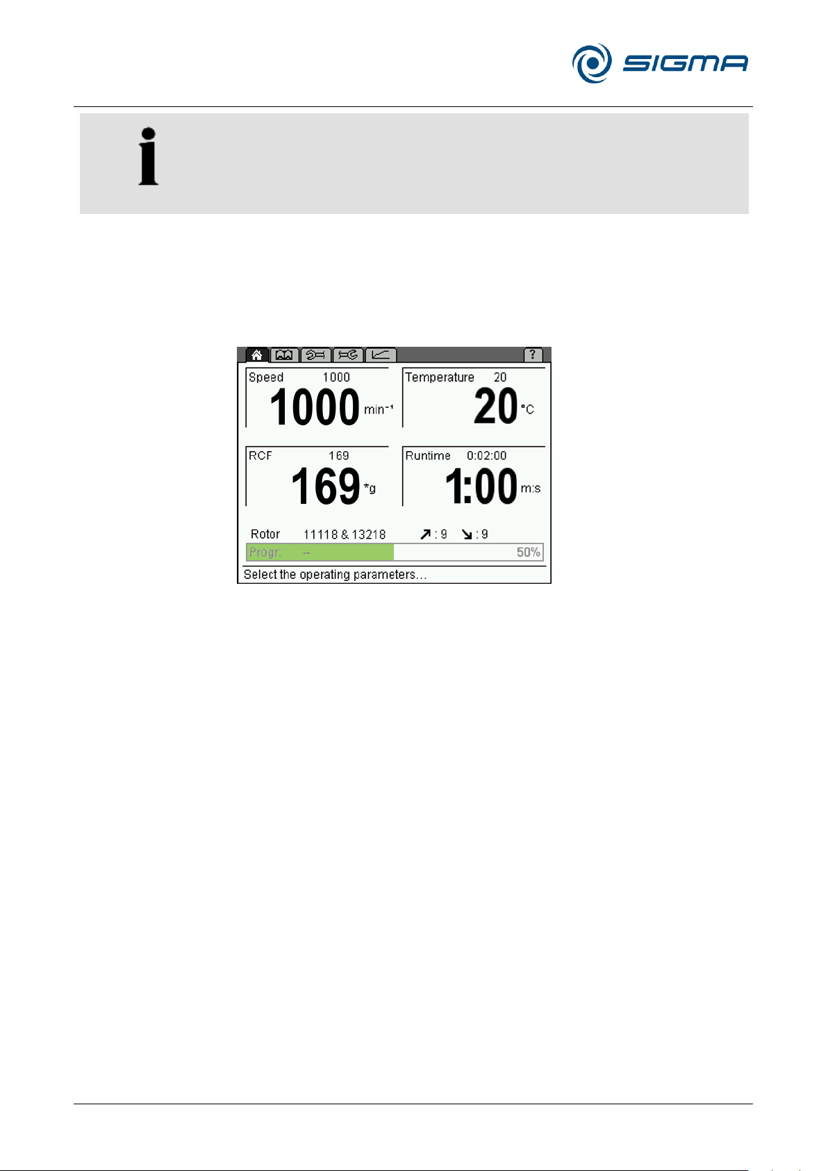
Refrigerated Centrifuge Sigma 8KS
Refrigerated Centrifuge Sigma 8KBS
6 Using the centrifuge
52 / 131
Version 08/2012, Rev. 2.5 of 02/07/2018 • sb
Translation of the original operating manual, part no. 0702502
NOTE
If the "RAPID_TEMP" program is used, the temperature of the unloaded
aluminium bucket will be displayed. If samples, which have not been
precooled, are placed into the buckets, the displayed temperature will
deviate from the actual sample temperature.
Progress indicator
The progress indicator provides a quick overview of the remaining runtime
of the running centrifugation run. For this purpose, a green progress bar
and percentage value are displayed in the program field.
Fig. 28: Progress indicator during a centrifugation run
After the completion of the centrifugation run, the progress indicator
remains at 100% until
• the lid is opened,
• a parameter is changed,
• a program is loaded, saved, or deleted, or
Pos: 156 /010 Universalmodule/Seiten wechsel @ 0\mod_1202116244312_0.d ocx @ 105 @ @ 1
• a new centrifugation run is started.
Page 53
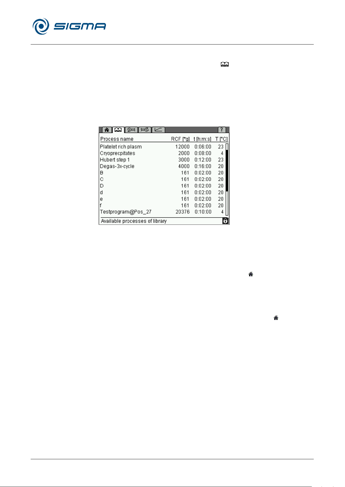
Refrigerated Centrifuge Sigma 8KS
Refrigerated Centrifuge Sigma 8KBS
6 Using the centrifuge
Version 08/2012, Rev. 2.5 of 02/07/2018 • sb
53 / 131
Translation of the original operating manual, part no. 0702502
Pos: 157 /100 Sigma/100 BA Zentrifugen Sig ma (Standardmodule)/060 Betrieb_ Spincontrol L+S/Spincontrol S (Zent7)/060- 0030-0020-0055 Menü Prozessbi bliothek @ 27\mod_1405320209123_68.d ocx @ 193276 @ 4 @ 1
6.3.2.6 Process library menu
The process library can be opened via the " " symbol on the menu bar. It
provides the user with an overview of all of the stored programs as
processes.
The processes are listed with their name, RCF, runtime, and temperature
(exception: the "RAPID_TEMP" program will not be listed).
The order of the processes corresponds to their storage locations on the
program list. Empty storage locations will not be displayed. If more than 11
programs have been stored, the user can scroll through the list.
Fig. 29: Process library menu
Loading a process
• In the process library, select the desired process by turning the function
knob. Press the function knob in order to confirm the selection.
The process will be loaded and the "Standard" menu will be displayed.
Starting a process
• In the process library, select the desired process by turning the function
knob. Then, press the start button.
The process will be loaded and started. The "Standard" menu will be
Pos: 158 /010 Universalmodule/Seiten wechsel @ 0\mod_1202116244312_0.d ocx @ 105 @ @ 1
displayed.
Page 54
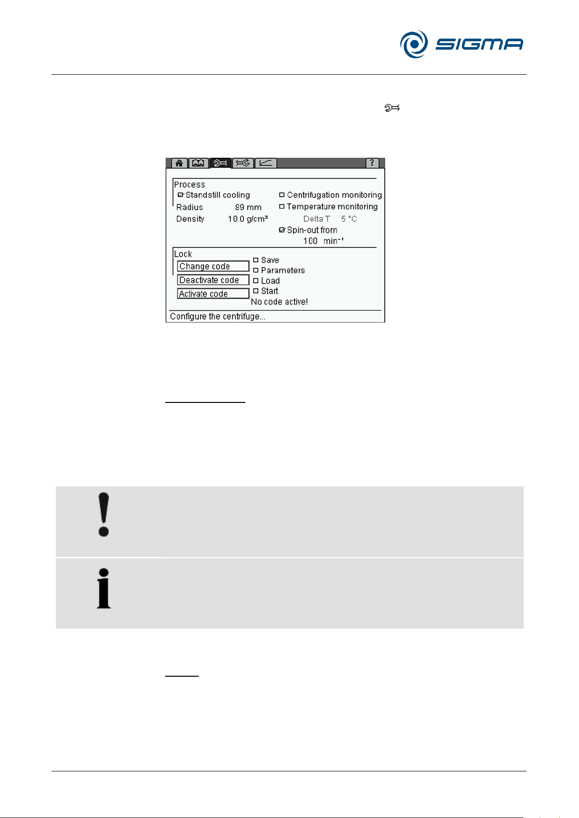
Refrigerated Centrifuge Sigma 8KS
Refrigerated Centrifuge Sigma 8KBS
6 Using the centrifuge
54 / 131
Version 08/2012, Rev. 2.5 of 02/07/2018 • sb
Translation of the original operating manual, part no. 0702502
CAUTION
Unmoved air in the rotor chamber leads to an incorrect measuring and
control behaviour and causes the compressor to freeze over. At
temperatures below 0°C, aqueous liquids will freeze, thereby preventing
sedimentation.
• Do not cool the rotor below 0°C at a standstill.
NOTE
The centrifuge is equipped with the "RAPID_TEMP" program. This
program is used to precool the rotor chamber quickly under defined
conditions (see chapter 6.3.2.5 - "Standard menu", Program list).
Pos: 159 /100 Sigma/100 BA Zentrifugen Sig ma (Standardmodule)/060 Betrieb _Spincontrol L+S/Spincontrol S (Zent7)/0 60-0030-0020-0060 Menü Paramet er - nur KS @ 27\mod_1405320218640 _68.docx @ 193305 @ 4 @ 1
6.3.2.7 Parameters menu
The "Parameters" menu is symbolised by the " " symbol on the menu
bar. It is used to specify various conditions for the centrifugation. These
conditions are used to monitor the process and to control access to the
centrifuge.
Fig. 30: Menu "Parameters"
Process
Standstill cooling
Depending on the substances to be centrifuged, it may make sense to
precool the centrifuge. The precooling prevents the cooled samples in the
uncooled centrifuge from heating up to an inadmissible temperature level.
If the standstill cooling function is activated, the centrifuge starts to precool
after it is switched on. In the runtime field, the symbol "" is displayed. The
lid must be closed.
Radius
The radius determines the value of the relative centrifugal force (RCF) that
the sample is subjected to. Normally, the maximum RCF value is displayed.
If the value is reduced manually, a downward facing arrow "" will be
displayed in the RCF field.
Page 55
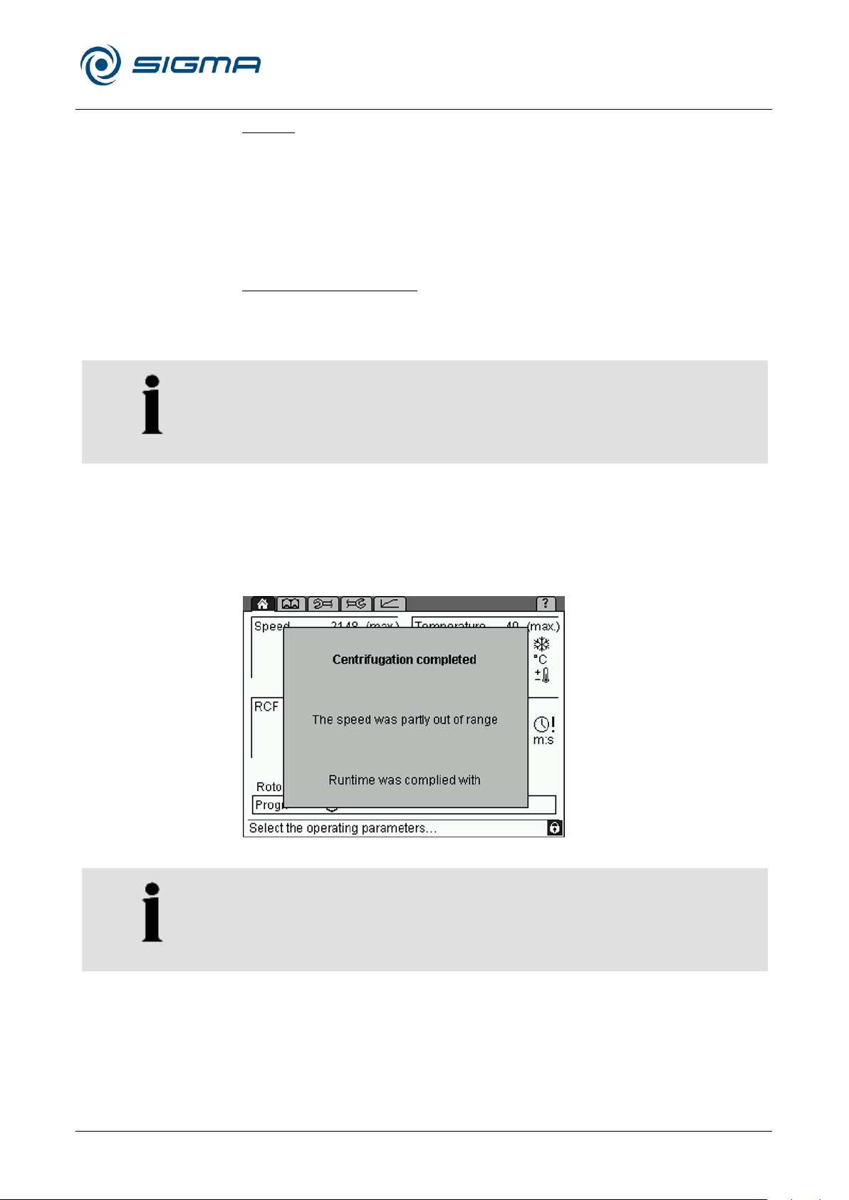
Refrigerated Centrifuge Sigma 8KS
Refrigerated Centrifuge Sigma 8KBS
6 Using the centrifuge
Version 08/2012, Rev. 2.5 of 02/07/2018 • sb
55 / 131
Translation of the original operating manual, part no. 0702502
NOTE
If the function is activated during a centrifugation run, the monitoring
process will not be started until the start of the next centrifugation run.
NOTE
If the centrifugation monitoring system is used in combination with free
acceleration or deceleration curves, unjustified error messages may result
in certain cases.
Density
This setting is useful for glass vessels. If the density of the liquid to be
centrifuged is higher than 1.2 g/cm3, the value must be adapted manually in
order to prevent the glass vessel from breaking. This will reduce the
maximum possible final speed (see chapter 2.2.2.2 - "Density"). The
reduction will be represented by a downward facing arrow "" in the speed
field. Values between 1.2 and 10.0 g/cm3 are possible.
Centrifugation monitoring
The centrifugation monitoring function enables the continuous monitoring of
the speed and runtime parameters during the centrifugation.
• Activate the centrifugation monitoring function by clicking.
The centrifugation monitoring function compares the speed values of the
current run with the reference values that are stored in the control unit.
After every run, it issues a corresponding message.
The runtime is considered faulty if the centrifugation run had to be stopped
prematurely.
Fig. 31: Example of a centrifugation monitoring message
Page 56
Refrigerated Centrifuge Sigma 8KS
Refrigerated Centrifuge Sigma 8KBS
6 Using the centrifuge
56 / 131
Version 08/2012, Rev. 2.5 of 02/07/2018 • sb
Translation of the original operating manual, part no. 0702502
NOTE
The delta T temperature monitoring system remains inactive as long as the
"RAPID_TEMP" program is active (see chapter 6.3.2.5 - "Standard menu",
"Program "RAPID_TEMP"").
NOTE
A spin-out, in particular with heavy rotors and at high speeds, can take a
lot of time! (Depending on the rotor and load, the speed will be reduced by
approximately 0.5 to 1 rpm per second.)
Temperature monitoring
The control system includes a temperature monitoring function. If the actual
temperature difference with regard to the set value deviates from the set
temperature difference, the centrifuge will stop and an error message will
be issued.
• Activate the temperature monitoring function by clicking.
• Adjust the desired "Delta T" limit value in steps of 1°C or 1°F and
confirm the setting.
If the temperature monitoring function is active, the symbol " " is displayed
in the temperature field of the "Standard" menu.
In this case, the centrifuge can only be started if the current temperature is
between the preset temperature in the "Standard" menu and the "Delta T"
limit value.
If the temperature leaves this range during the centrifugation run, an error
message will be displayed and the centrifuge will be decelerated to a
complete standstill.
Spin-out from…
If this function is active, the brake will be deactivated when the actual
speed is below the set speed. As a result, the rotor will spin out in a
brakeless manner.
If the spin-out is active, "+0" is displayed next to the deceleration curve.
• The spin-out can be interrupted by a quick stop or by restarting the
centrifuge.
Page 57
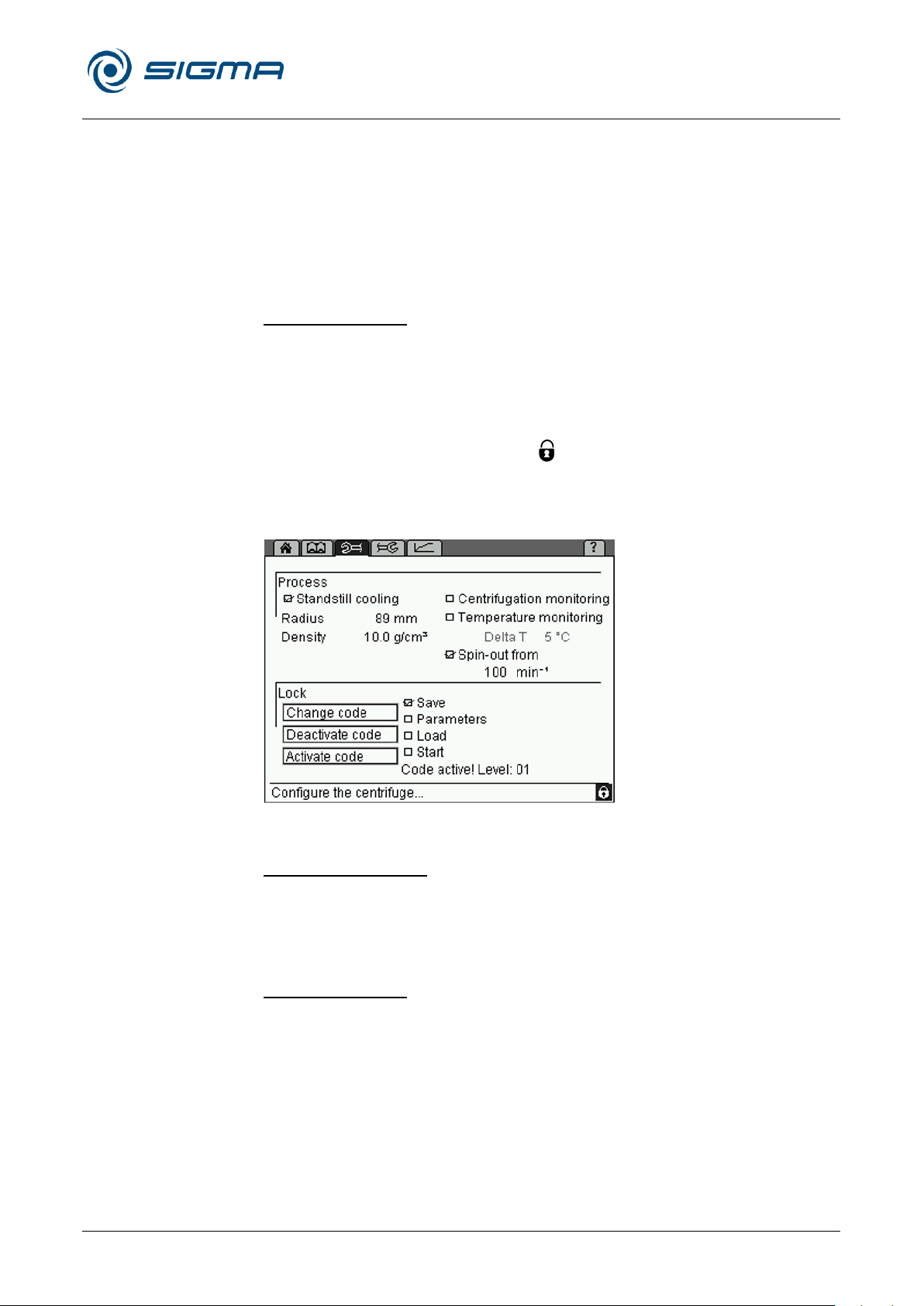
Refrigerated Centrifuge Sigma 8KS
Refrigerated Centrifuge Sigma 8KBS
6 Using the centrifuge
Version 08/2012, Rev. 2.5 of 02/07/2018 • sb
57 / 131
Translation of the original operating manual, part no. 0702502
Lock
In order to prevent any unauthorised use of the centrifuge, the following
functions can be blocked:
• Saving of programs (level 01)
• Changing of parameters, short run (level 02)
• Loading of programs (level 03)
• Start button (level 04)
Blocking a function
• Select the function that is to be blocked. The lower levels will also be
automatically selected (if, for example, the "Parameters" function is
selected, the "Save" function will also be selected).
• Select the button "Activate code".
• Enter a four-digit code and confirm the entry.
The lock is now active. The symbol " " will be displayed in the status line
and the lock level will be indicated.
If changes are made after a function has been blocked, the system will ask
for the code prior to executing the change.
Fig. 32: "Parameters" menu with an active lock (level 01)
Unblocking a function
• Select the button "Deactivate code".
• Enter the code and confirm the entry.
The lock is now deactivated.
Changing the code
• Select the button "Change code".
• Enter the old code and confirm the entry.
• Enter the new code.
• For safety reasons, the code must be entered a second time.
Pos: 160 /010 Universalmodule/Seiten wechsel @ 0\mod_1202116244312_0.d ocx @ 105 @ @ 1
The code is now changed.
Page 58
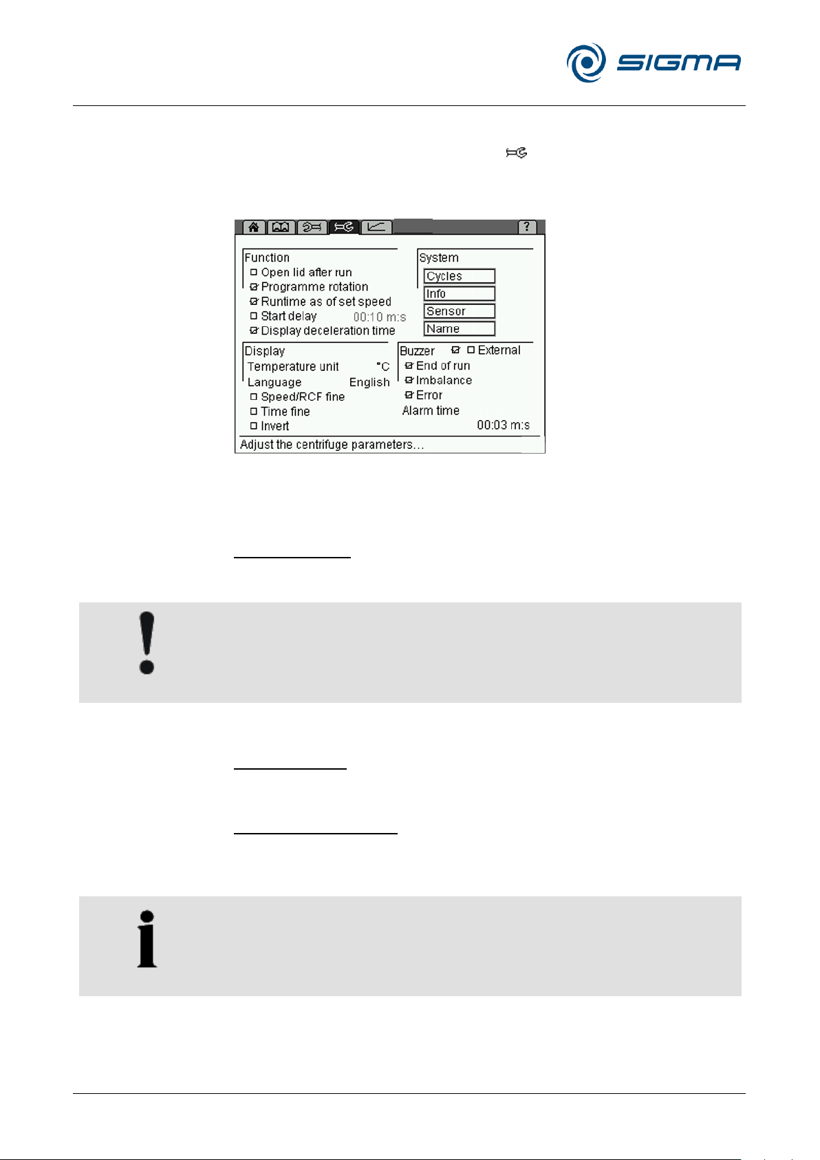
Refrigerated Centrifuge Sigma 8KS
Refrigerated Centrifuge Sigma 8KBS
6 Using the centrifuge
58 / 131
Version 08/2012, Rev. 2.5 of 02/07/2018 • sb
Translation of the original operating manual, part no. 0702502
CAUTION
When the lid is open, the cooling is not active. The sample may warm up!
NOTE
In the program mode, this function can be saved separately for every
program. In this case, the symbol "!" will be displayed under the runtime
of the detailed program description.
Pos: 161 /100 Sigma/100 BA Zentrifugen Sig ma (Standardmodule)/060 Betrieb_ Spincontrol L+S/Spincontrol S (Zent7)/060- 0030-0020-0070 Menü Setup @ 2 7\mod_1405320225479_68.docx @ 193361 @ 4 @ 1
6.3.2.8 Setup menu
The "Setup" menu is symbolised by the " " symbol on the menu bar. It is
used to perform basic settings concerning the control system of the
centrifuge. It enables the optimum adaptation of the centrifuge to its specific
area of application.
Fig. 33: Menu "Setup"
Function
Open lid after run
The automatic lid opening function ensures that the lid opens when the
rotor has stopped.
Program rotation
See chapter 6.3.3.5 - "Automatic program rotation".
Runtime as of set speed
If this function is active, the runtime will not be measured until the set speed
is reached. In the "Standard" menu, the symbol "!" will be displayed in the
runtime field.
Page 59
Refrigerated Centrifuge Sigma 8KS
Refrigerated Centrifuge Sigma 8KBS
6 Using the centrifuge
Version 08/2012, Rev. 2.5 of 02/07/2018 • sb
59 / 131
Translation of the original operating manual, part no. 0702502
NOTE
Regardless of the fine adjustment, the step size increases when the
function knob is turned quickly.
Start delay
If the start delay function is active, the centrifuge will not start until the
preset time has elapsed. The symbol "" will be displayed in the runtime
field.
Display deceleration time
In the activated mode, the deceleration time will be displayed instead of the
runtime during and after the deceleration process. Below the time display,
the symbol " " will be displayed. During a deceleration process, the
symbol flashes. Once the deceleration is complete, it is displayed in a
permanent manner.
Display
Temperature unit
The temperature can be displayed in °C (Celsius) or °F (Fahrenheit).
Language
The control system can be used in various language versions.
If a language is selected by mistake, it can be changed on any screen as
follows:
• Press and hold the stop button.
• Turn the function knob one notch to the left and then one notch to the
right.
• Release the stop button. The "Language" window will be displayed.
• Select the desired language.
Speed/RCF fine and Time fine
This menu item can be used to preselect the set speed in steps of 1 rpm
(instead of 100 rpm), the RCF value in steps of 1 x g (instead of 10 x g),
and the set time in steps of 1 min or 1 sec (instead of 10 min or 10 sec).
Invert
If this function is activated, the display switches from the standard setting
with a bright background and dark writing to a dark background with bright
writing.
Page 60

Refrigerated Centrifuge Sigma 8KS
Refrigerated Centrifuge Sigma 8KBS
6 Using the centrifuge
60 / 131
Version 08/2012, Rev. 2.5 of 02/07/2018 • sb
Translation of the original operating manual, part no. 0702502
NOTE
Values can neither be entered nor changed in the menus "Cycles", "Info",
and "Sensor".
System
Cycles
This field shows the number of cycles as well as the runtime of the rotor
and buckets that are used.
Info
This item provides information on the software versions that are used in this
centrifuge.
Sensor
The sensor mode is reserved for the service personnel.
Name
In this field, an identification will be assigned to the centrifuge.
• The letters and characters can be entered when the cursor flashes in
the text field. Turn the function knob in order to select a character and
press it to confirm the selection. Then, press the knob again in order to
enter the next character. Pressing the arrow button ← will delete the
last character. The maximum number of characters is 19.
• When the name is complete, select the option "Accept" and confirm it.
Buzzer (signal)
With this function, a warning sound signal can be selected for
• the end of a centrifugation run,
• an imbalance message,
• an error message.
The duration of the warning signal can be specified.
External
This function is only available if the centrifuge is equipped with the option
for the input and output of data (external signal, floating switch) (see
Pos: 162 /010 Universalmodule/Seiten wechsel @ 0\mod_1202116244312_0.d ocx @ 105 @ @ 1
chapter 6.3.4 - "Options for data input and output").
Page 61
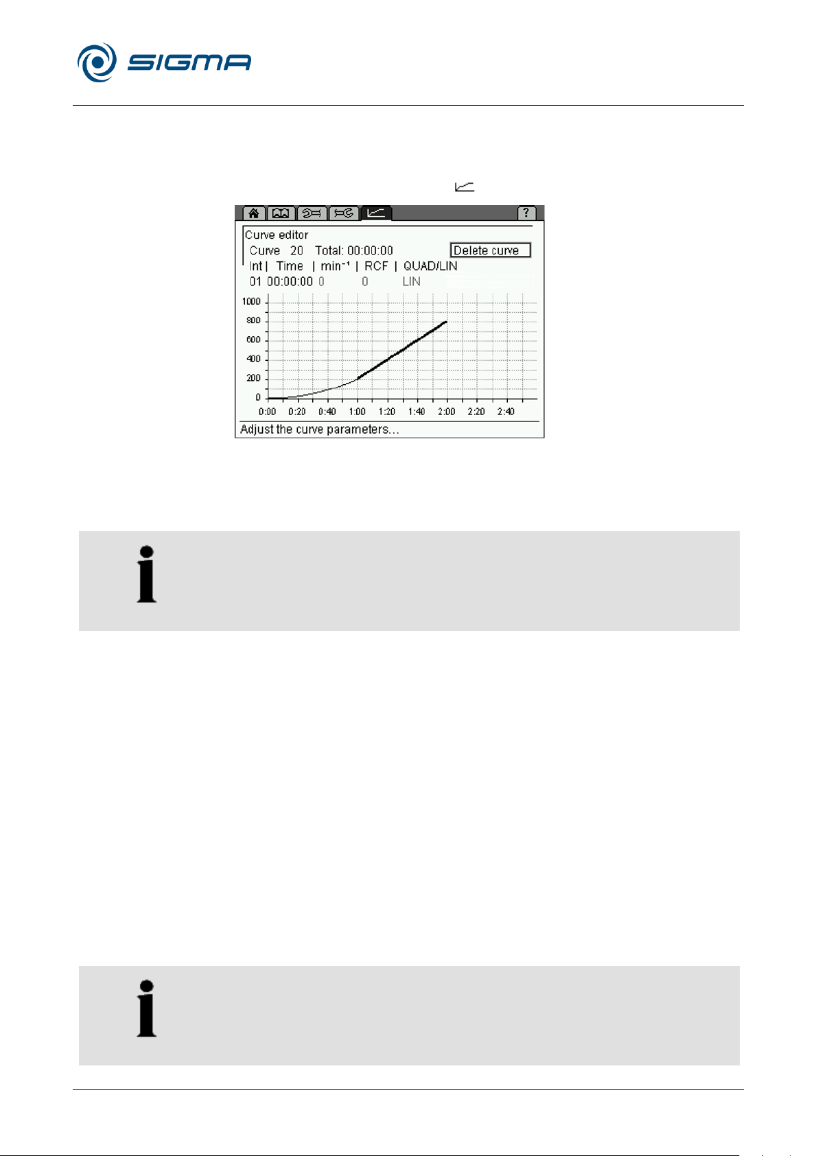
Refrigerated Centrifuge Sigma 8KS
Refrigerated Centrifuge Sigma 8KBS
6 Using the centrifuge
Version 08/2012, Rev. 2.5 of 02/07/2018 • sb
61 / 131
Translation of the original operating manual, part no. 0702502
NOTE
During a centrifugation run, curves can only be displayed. They cannot be
changed or deleted.
NOTE
Only the last curve interval can be changed retroactively.
Pos: 163 /100 Sigma/100 BA Zentrifugen Sig ma (Standardmodule)/060 Betrieb_ Spincontrol L+S/Spincontrol S (Zent7)/060- 0030-0020-0080 Menü Kur ve @ 27\mod_1405320228169_68.docx @ 193389 @ 4 @ 1
6.3.2.9 Curve menu
This menu is used to create and edit customised acceleration and
deceleration curves (see chapter 11.3 - "Acceleration and deceleration
curves"). It is symbolised by the " " symbol on the menu bar.
Fig. 34: Menu "Curve"
Creating or changing an acceleration curve
• Select the "Curve" menu. The curve editor will be displayed.
• Select a curve number between 20 and 29 in the input field "Curve". If
the curve number is already used, the stored curve will be displayed.
• The input field "Int" is used to specify the interval number of the
process. Up to ten intervals can be entered for a curve.
• Enter the interval time of the current interval into the input field "Time".
While doing so, certain restrictions must be taken into consideration
(see below).
• Enter the desired acceleration under "min-1" (rpm) or "RCF". While doing
so, certain restrictions must be taken into consideration (see below).
The values are interdependent.
• In the first interval, "QUAD/LIN" can be used to select a linear or
quadratic rise. All of the other intervals are linear.
The field "Total" shows the total runtime of the process. The maximum total
runtime of a curve depends on the slope of the curve and on the final speed
of the rotor.
Page 62
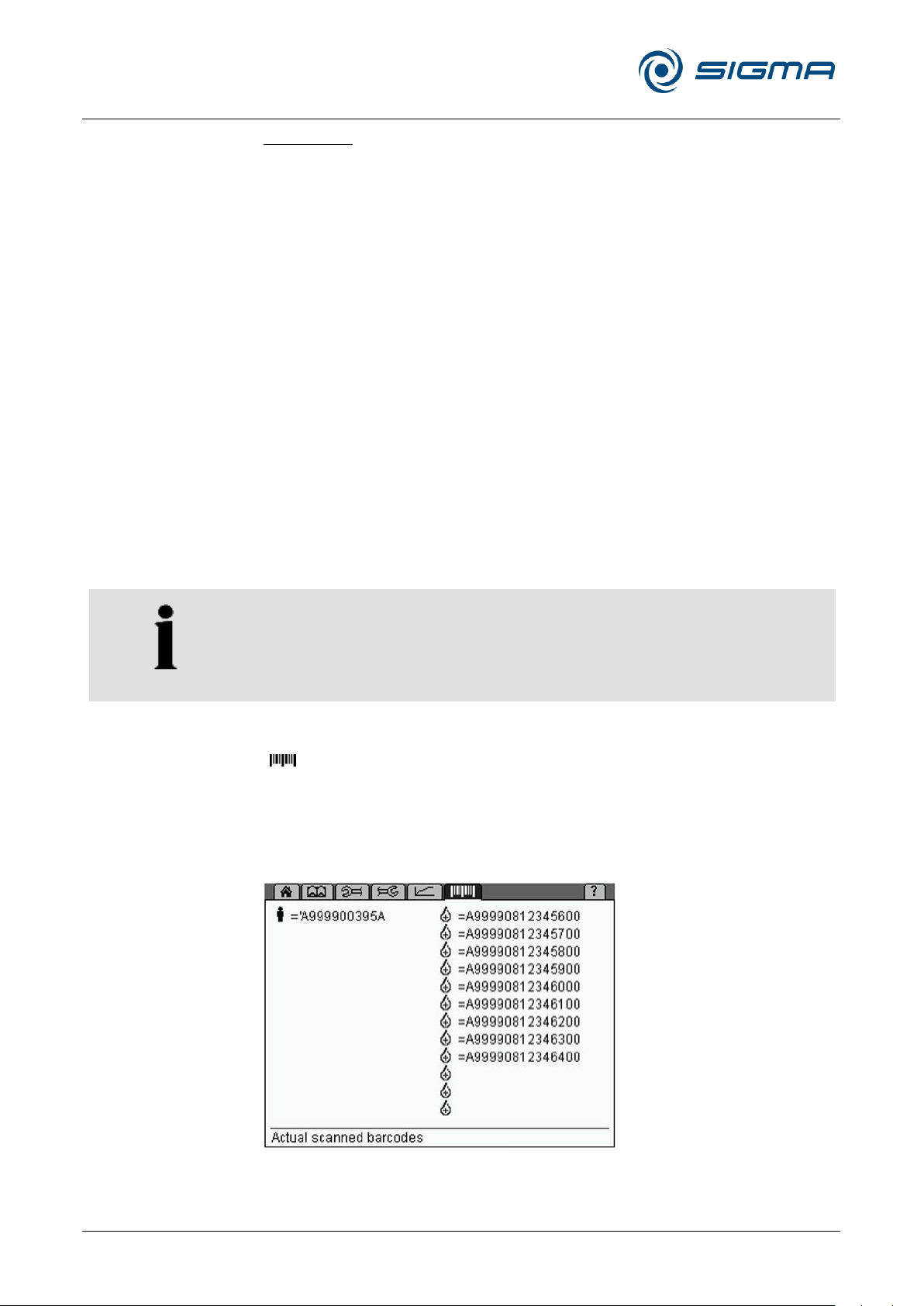
Refrigerated Centrifuge Sigma 8KS
Refrigerated Centrifuge Sigma 8KBS
6 Using the centrifuge
62 / 131
Version 08/2012, Rev. 2.5 of 02/07/2018 • sb
Translation of the original operating manual, part no. 0702502
NOTE
In order to connect a barcode scanner, the centrifuge must be equipped
with a second RS232 interface and a corresponding circuit board.
Restrictions
• Acceleration and deceleration curves can include intervals with a
positive slope as well as intervals with a negative slope and also
intervals with 0 slope.
• The slope of the curve intervals can be 1 min-1/sec (rpm/sec) minimum
and 1000 min-1/sec (rpm/sec) maximum.
• Quadratic curve intervals are only possible between 0 and 1000 min-1
(rpm) maximum. If a final speed > 1000 min-1 (rpm) is selected, this
interval will automatically become linear above 1000 min-1 (rpm).
• The possible runtime results from the maximum possible speed
(depending on the rotor) and from the slope limitation.
Example 1: Start speed 0 min-1 (rpm), final speed 100 min-1 (rpm),
runtime 1 hour not possible, since the necessary slope < 0.03 min-1
(rpm), which means that it is beyond the defined range.
Example 2: Start speed 0 min-1 (rpm), final speed 15000 min-1 (rpm),
runtime 10 sec. not possible, since the necessary slope is 1500 min-1
Pos: 164 /010 Universalmodule/ Leerzeile @ 0\mod_1202116244500_0.docx @ 1 14 @ @ 1
Pos: 165 /100 Sigma/100 BA Zentrifugen Sig ma (Standardmodule)/060 Betrieb_ Spincontrol L+S/Spincontrol S (Zent7)/060- 0030-0020-0085 Menü Barcode @ 27\mod_1405320229578_68.docx @ 193402 @ 4 @ 1
(rpm), which means that it is beyond the defined range.
6.3.2.10 Option: Barcode menu
If the centrifuge is equipped with the barcode scanner function, the symbol
" " will be displayed on the menu bar. In order to use this function, a PC
and a barcode scanner must be connected to the RS232 interface.
The "Barcode" menu shows all of the codes that are stored in the control
system. Data structure 020 is displayed in the left-hand area of the screen,
and data structure 001 is in the right-hand area. Free storage locations are
symbolised by symbols without any code.
Fig. 35: Barcode menu
Page 63

Refrigerated Centrifuge Sigma 8KS
Refrigerated Centrifuge Sigma 8KBS
6 Using the centrifuge
Version 08/2012, Rev. 2.5 of 02/07/2018 • sb
63 / 131
Translation of the original operating manual, part no. 0702502
NOTE
In the event of a mains power failure, all the codes that have been
scanned in so far will be lost and must be scanned again.
With the barcode scanner, the barcodes can be scanned directly at the
centrifuge during the loading process. The centrifugation data can be
enquired cyclically (automatically) by the PC. Once a centrifugation run is
complete, the PC can detect this and save the result (centrifugation data
with barcodes).
Barcode commands
Setting a barcode: "setbarcode"
Every code must be set separately. This is done automatically by way of
the scanner. Barcodes will only be accepted under the following conditions:
• There is no active centrifugation run.
• There are not any barcodes stored in the system which have already
been used for a centrifugation run.
• The barcode does not already exist.
• It is an ISBT 128 barcode with the data structure 001 (donation
identification number) and there are fewer than 12 of these codes
stored in the system.
• It is an ISBT 128 barcode with the data structure 020 (staff member
identification number) and there are not any barcodes with this data
structure stored in the system.
If the barcode is accepted, the data of the last centrifugation run will be
automatically deleted and the "Barcode" menu will be displayed.
Reading out the stored barcodes: "getbarcodes"
All of the codes will be output in one response. This leads to the following
possible response formats:
• No codes are stored
syntax "Barcodes none\r\n"
• Only codes with the data structure 001 are stored
syntax "Barcodes abc, def,…\r\n" (abc, def,… = barcodes)
• Only codes with the data structure 020 are stored
syntax "Barcodes abc (staff)\r\n" (abc = barcode)
• Codes with the data structures 001 and 020 are stored
syntax: "Barcodes abc (staff), def,…\r\n" (abc, def,… = barcodes)
Page 64
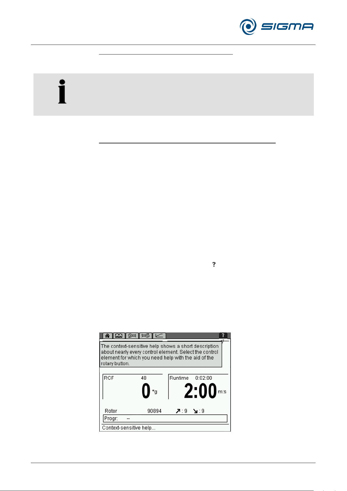
Refrigerated Centrifuge Sigma 8KS
Refrigerated Centrifuge Sigma 8KBS
6 Using the centrifuge
64 / 131
Version 08/2012, Rev. 2.5 of 02/07/2018 • sb
Translation of the original operating manual, part no. 0702502
NOTE
This command will not be accepted unless the centrifuge is at a standstill.
Pos: 166 /010 Universalmodule/ Leerzeile @ 0\mod_1202116244500_0.docx @ 1 14 @ @ 1
Pos: 167 /100 Sigma/100 BA Zentrifugen Sig ma (Standardmodule)/060 Betrieb_ Spincontrol L+S/Spincontrol S (Zent7)/0 60-0030-0020-0090 Menü Hilfe @ 27 \mod_1405320230870_68.docx @ 19 3417 @ 4 @ 1
6.3.2.11 Help menu
Deleting the stored barcodes: "deletebarcodes"
This command is used to delete all of the stored barcodes.
The "Barcode" menu will be updated.
Reading out the data of the last centrifugation run: "getlastrun"
The response to this command includes information concerning the
parameters and status of the last centrifugation run (for the exact format of
the data see chapter 11.6 - "Serial Control Interface Specification").
If barcodes have been stored, they will also be output as follows:
• Syntax data structure 001:
"Barcode;x;abc\r\n" (x = serial number starting at 1, abc = barcode)
• Syntax data structure 020:
"Barcode;Staff Member ID;abc\r\n" (abc = barcode)
The enquiry can be performed at any time (before, during, and after the
centrifugation run). Depending on the time of the enquiry, some of the
results may still be unknown.
The help function is symbolised by the " " symbol on the menu bar. It
provides a short description of the control elements of the selected option.
Activating and deactivating the help function
• Select the question mark on the menu bar and press the function knob.
• Quit the help function by selecting the question mark and by pressing
the function knob again.
Parameters can still be changed when the help function is activated.
Pos: 168 /010 Universalmodule/Seiten wechsel @ 0\mod_1202116244312_0.d ocx @ 105 @ @ 1
Fig. 36: Menu "Help"
Page 65
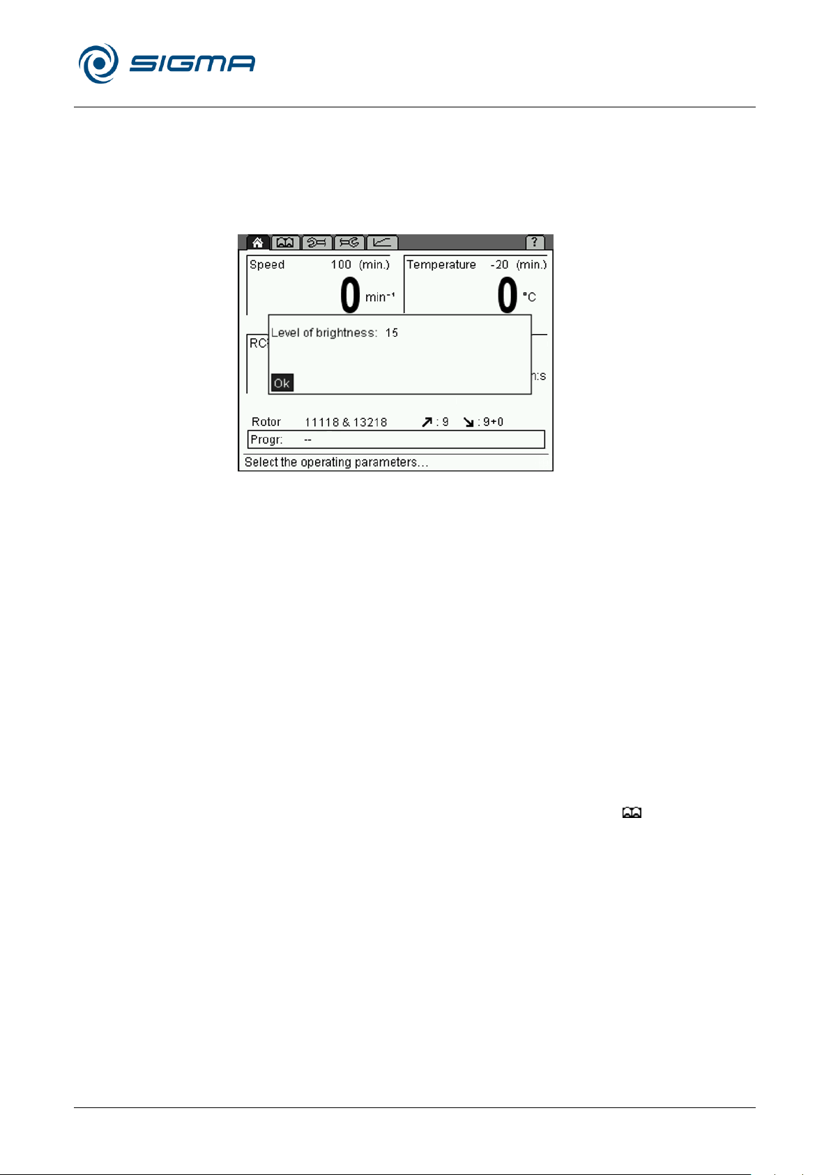
Refrigerated Centrifuge Sigma 8KS
Refrigerated Centrifuge Sigma 8KBS
6 Using the centrifuge
Version 08/2012, Rev. 2.5 of 02/07/2018 • sb
65 / 131
Translation of the original operating manual, part no. 0702502
Pos: 169 /100 Sigma/100 BA Zentrifugen Sig ma (Standardmodule)/060 Betrieb_ Spincontrol L+S/Spincontrol S (Zent7)/060- 0030-0020-0100 Kontraständerung @ 27\mod_1405320232376_68.doc x @ 193431 @ 4 @ 1
6.3.2.12 Changing the contrast
To change the contrast:
• Press and hold the stop button and turn the function knob one notch to
the left. A dialog box will be displayed once the stop button is released.
• Adjust the contrast of the centrifuge display and confirm the change.
Pos: 170 /010 Universalmodule/ Leerzeile @ 0\mod_1202116244500_0.docx @ 1 14 @ @ 1
Pos: 171 /010 Universalmodule/ Leerzeile @ 0\mod_1202116244500_0.docx @ 1 14 @ @ 1
Pos: 172 /100 Sigma/100 BA Zentrifugen Sig ma (Standardmodule)/060 Betrieb_ Spincontrol L+S/Spincontrol S (Zent7)/060- 0030-0030 Programmbetrieb @ 2 7\mod_1405320235093_68.docx @ 193 459 @ 3 @ 1
Fig. 37: Dialog box for changing the contrast
6.3.3 Program mode
A program contains all of the data that are required for a centrifuge run.
Certain sedimentation results can be repeated under identical conditions.
Programs can be loaded, executed, edited, and deleted when the
centrifuge is at a standstill.
A maximum of 60 programs can be stored under the numbers 1-60. The
program "RAPID_TEMP" does not occupy any storage location and cannot
be deleted. It is used to bring the centrifuge to a specific temperature
without any vessels.
"--" means that the values that are currently set are not a stored program.
The programs can be protected against unauthorised use, modification, or
deletion with the aid of a code (see chapter 6.3.2.7 - "Parameters menu").
Pos: 173 /010 Universalmodule/Seiten wechsel @ 0\mod_1202116244312_0.d ocx @ 105 @ @ 1
Stored programs are listed in the "Process library" menu .
Page 66
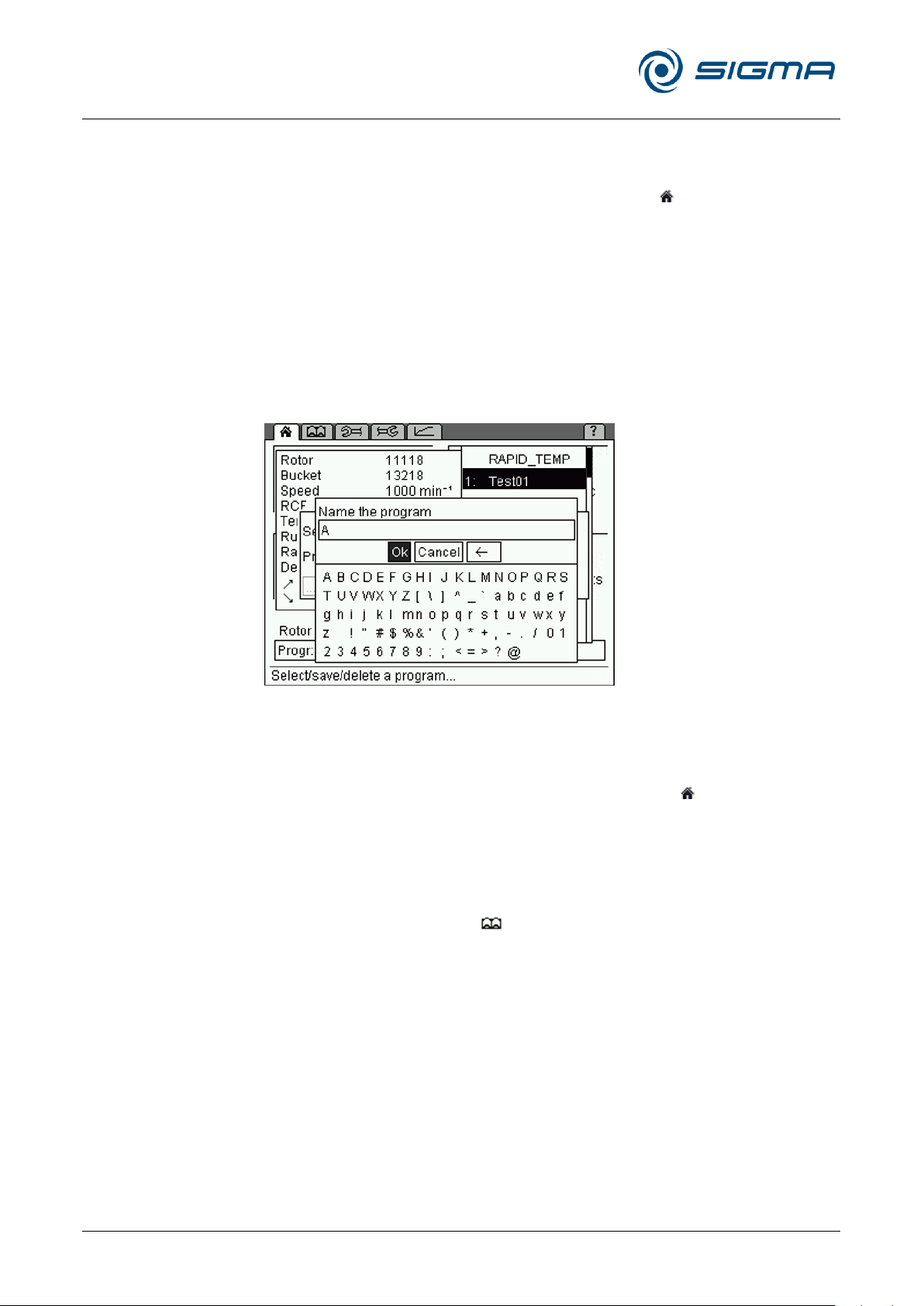
Refrigerated Centrifuge Sigma 8KS
Refrigerated Centrifuge Sigma 8KBS
6 Using the centrifuge
66 / 131
Version 08/2012, Rev. 2.5 of 02/07/2018 • sb
Translation of the original operating manual, part no. 0702502
Pos: 174 /100 Sigma/100 BA Zentrifugen Sig ma (Standardmodule)/060 Betrieb_ Spincontrol L+S/Spincontrol S (Zent7)/0 60-0030-0030-0010 Programm speic hern @ 27\mod_1405320237832_68.doc x @ 193487 @ 4 @ 1
6.3.3.1 Saving a program
• Enter the parameters that are to be included in the program.
• Select the option "Progr" in the "Standard" menu and confirm the
selection. The program list will be displayed.
• Select a storage location from the program list.
• Save the program under the desired name. The letters and characters
can be entered when the cursor flashes in the text field.
– Turn the function knob in order to select a letter and press it to
– Pressing the arrow button will delete the last character.
• When the program name is complete, select "OK" and confirm it.
The program will be saved and the "Standard" menu will be displayed.
confirm the selection. Then, the next character can be selected.
Pos: 175 /010 Universalmodule/ Leerzeile @ 0\mod_1202116244500_0.docx @ 1 14 @ @ 1
Pos: 176 /100 Sigma/100 BA Zentrifugen Sig ma (Standardmodule)/060 Betrieb_ Spincontrol L+S/Spincontrol S (Zent7)/060- 0030-0030-0020 Programm lade n @ 27\mod_1405320240684_68.docx @ 193515 @ 4 @ 1
Fig. 38: Assignment of a program name prior to saving the program
6.3.3.2 Loading a program
• Select the option "Progr" from the "Standard" menu and confirm the
selection by pressing the function knob. The program list will be
displayed.
• Select the desired program from the list and confirm the selection by
pressing the function knob.
Or:
• Open the process library , select the desired program, and confirm
the selection by pressing the function knob.
The program will be loaded and the "Standard" menu will be displayed.
Page 67
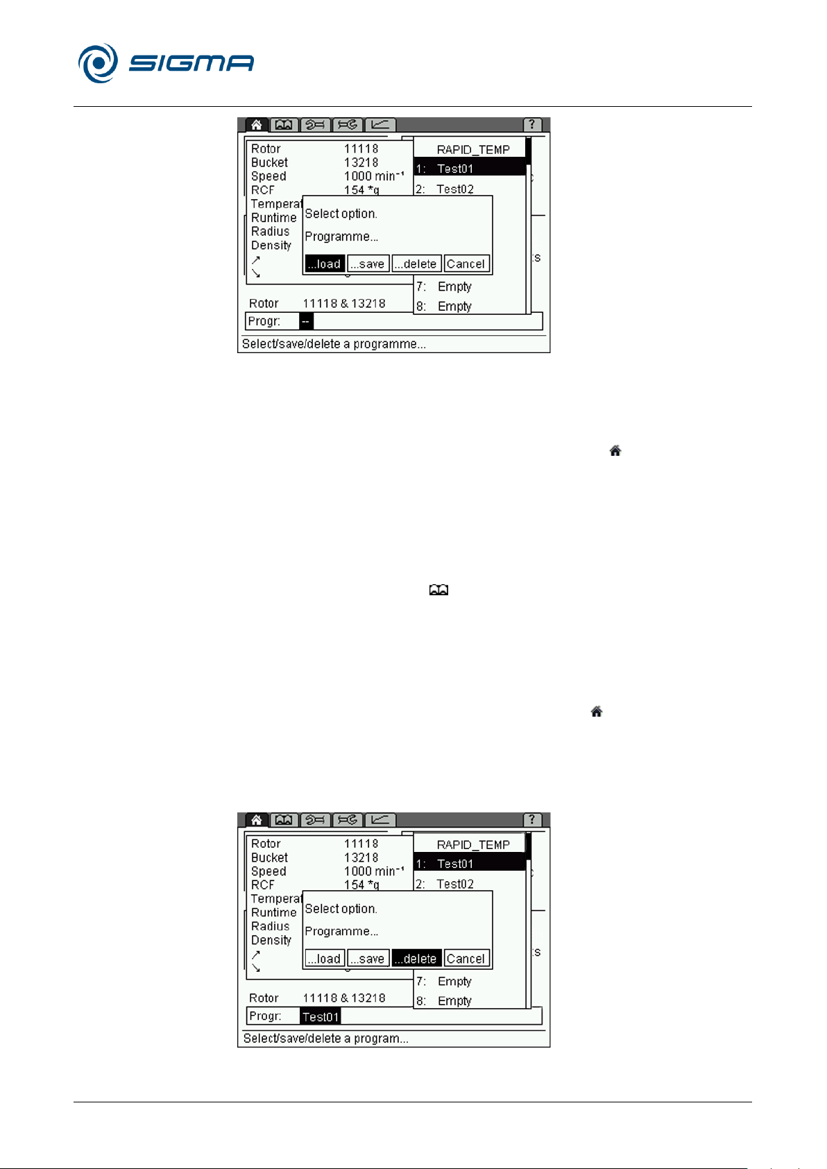
Refrigerated Centrifuge Sigma 8KS
Refrigerated Centrifuge Sigma 8KBS
6 Using the centrifuge
Version 08/2012, Rev. 2.5 of 02/07/2018 • sb
67 / 131
Translation of the original operating manual, part no. 0702502
Pos: 177 /010 Universalmodule/ Leerzeile @ 0\mod_1202116244500_0.docx @ 1 14 @ @ 1
Pos: 178 /100 Sigma/100 BA Zentrifugen Sig ma (Standardmodule)/060 Betrieb_ Spincontrol L+S/Spincontrol S (Zent7)/060- 0030-0030-0030 Programm ausfü hren @ 27\mod_1405320243642_68.d ocx @ 193543 @ 4 @ 1
Fig. 39: Loading a program
6.3.3.3 Executing a program
• Select the option "Progr" from the "Standard" menu and confirm the
selection by pressing the function knob. The program list will be
displayed.
• Select the desired program from the list and confirm the selection by
pressing the function knob.
• Press the start button.
Or:
• Open the process library , select the desired program, and press the
start button.
Pos: 179 /010 Universalmodule/ Leerzeile @ 0\mod_1202116244500_0.docx @ 1 14 @ @ 1
Pos: 180 /100 Sigma/100 BA Zentrifugen Sig ma (Standardmodule)/060 Betrieb_ Spincontrol L+S/Spincontrol S (Zent7)/060- 0030-0030-0040 Programm lösch en @ 27\mod_1405320245137_68.doc x @ 193557 @ 4 @ 1
The program will be executed and the "Standard" menu will be displayed.
6.3.3.4 Deleting a program
• Select the option "Progr" in the "Standard" menu and confirm the
selection. The program list will be displayed.
• Select the program that is to be deleted.
• Select the option "Delete" and confirm it.
The program will be deleted and the "Standard" menu will be displayed.
Pos: 181 /010 Universalmodule/Seiten wechsel @ 0\mod_1202116244312_0.d ocx @ 105 @ @ 1
Fig. 40: Deleting a program
Page 68
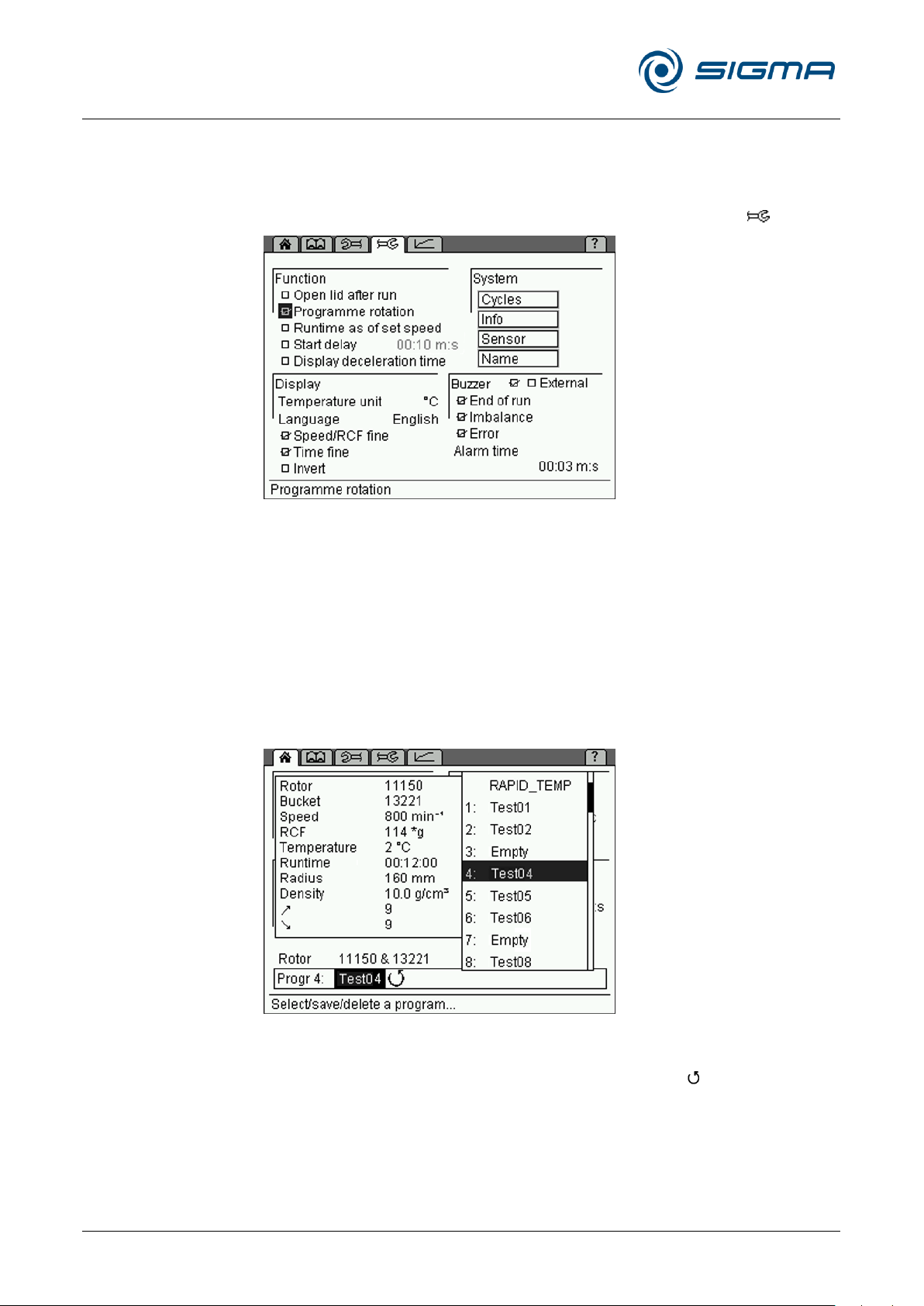
Refrigerated Centrifuge Sigma 8KS
Refrigerated Centrifuge Sigma 8KBS
6 Using the centrifuge
68 / 131
Version 08/2012, Rev. 2.5 of 02/07/2018 • sb
Translation of the original operating manual, part no. 0702502
Pos: 182 /100 Sigma/100 BA Zentrifugen Sig ma (Standardmodule)/060 Betrieb_ Spincontrol L+S/Spincontrol S (Zent7)/060- 0030-0030-0050 Automatische Prog rammrotation @ 27\mod_140532024 8329_68.docx @ 193585 @ 4 @ 1
6.3.3.5 Automatic program rotation
With the automatic program rotation, several programs can be executed
directly one after the other.
• Activate the "Program rotation" function in the "Setup" menu .
Fig. 41: Program rotation function
When a program is loaded while the program rotation function is active, this
program will be used as the start program for the rotation. After the
completion of the program, the next program on the program list will be
loaded automatically. The rotation continues up to the next empty storage
location and then restarts from the beginning (see the following illustration).
Example 1: Loading of Test04
Rotation: Test04, Test05, Test06, Test04,...
Example 2: Loading of Test05
Rotation: Test05, Test06, Test05,...
Pos: 183 /010 Universalmodule/Seiten wechsel @ 0\mod_1202116244312_0.d ocx @ 105 @ @ 1
Fig. 42: Automatic program rotation
While the program rotation function is active, the arrow " " is displayed in
the program line in the "Standard" menu.
Page 69

Refrigerated Centrifuge Sigma 8KS
Refrigerated Centrifuge Sigma 8KBS
6 Using the centrifuge
Version 08/2012, Rev. 2.5 of 02/07/2018 • sb
69 / 131
Translation of the original operating manual, part no. 0702502
Pos: 184 /100 Sigma/100 BA Zentrifugen Sig ma (Standardmodule)/060 Betrieb_ Spincontrol L+S/Spincontrol S (Zent7)/060- 0030-0040 Optionen zur Ein- und Ausgabe von Daten (nur 8KS) @ 27\m od_1405320253246_68.docx @ 193627 @ 3 @ 1
6.3.4 Options for data input and output
• Connection for a serial interface (depending on the model, partly
standard).
• External signal active DC 24 V, 0.5 A max. (part no. 17701)
• Floating switch AC 250 V max., 6 A (part no. 17702)
• Connection of a barcode scanner via a barcode extension board (see
Pos: 185 /010 Universalmodule/ Leerzeile @ 0\mod_1202116244500_0.docx @ 1 14 @ @ 1
Pos: 186 /010 Universalmodule/ Leerzeile @ 0\mod_1202116244500_0.docx @ 1 14 @ @ 1
Pos: 187 /100 Sigma/100 BA Zentrifugen Sig ma (Standardmodule)/060 Betrieb_ Spincontrol L+S/060-0040 Aussch alten @ 27\mod_1405319212716_68.docx @ 192591 @ 2 @ 1
chapter 6.3.2.10 - "Option: Barcode menu")
6.4 Switching the centrifuge off
• Open the centrifuge when it is not in use so moisture can evaporate.
Pos: 188 /010 Universalmodule/Abschnitt swechsel @ 0\mod_1202124514062_0. docx @ 418 @ @ 1
Pos: 189 /010 Universalmodule/Seiten wechsel @ 0\mod_1202116244312_0.d ocx @ 105 @ @ 1
• Switch the centrifuge off by pressing the mains power switch.
Page 70

Refrigerated Centrifuge Sigma 8KS
Refrigerated Centrifuge Sigma 8KBS
7 Malfunctions and error correction
70 / 131
Version 08/2012, Rev. 2.5 of 02/07/2018 • sb
Translation of the original operating manual, part no. 0702502
NOTE
Error messages can be eliminated by pressing the lid key. The error itself
will not be eliminated, but the centrifuge can be operated again.
Type of error
Possible reason
Correction
No indication on the display
No power in the mains supply
Check fuse in the mains supply
Power cord is not plugged in
Plug in power cord correctly
Fuses have tripped
Reactivate temperature fuse (see
chapter 5.4.1 - "Type of connection")
Mains power switch off
Switch mains power switch on
Centrifuge cannot be started:
start key LED is not illuminated
Several possible causes
Power off/on. If the error occurs
again, contact service
Centrifuge cannot be started:
lid key LED flashes
The lid lock is not closed correctly
Open and close the lid. If the error
occurs again, contact service
Centrifuge decelerates during
operation
Brief mains power failure
Press start key in order to restart the
centrifuge
System error
Power off/on. If the error occurs
again, contact service
Centrifuge decelerates during
operation, imbalance dialog box is
displayed
– Improper loading
– Centrifuge is inclined
– Drive problem
– Centrifuge was moved during run
Balance load and restart the
centrifuge. If the error occurs again,
contact service (see chapter 7.1.1 "Emergency lid release")
– Ungreased load- bearing bolts
Clean and grease load- bearing bolts
Lid cannot be opened
Lid lock has not released
Unlock the lid manuallyand contact
service
Lid seal sticks
Clean the lid seal and apply talcum
powder
Temperature value cannot be reached
(only for refrigerated centrifuges)
Condenser dirty (only air-cooled units)
Clean the condenser. If the error
occurs again, contact service
Pos: 190 /100 Sigma/100 BA Zentrifugen Sig ma (Standardmodule)/070 Störungen und Fehlersuche/070 Störungen und F ehlersuche=============== ============== @ 28\mod_1405320576 072_68.docx @ 194663 @ 1 @ 1
7 Malfunctions and error correction
Pos: 191 /100 Sigma/100 BA Zentrifugen Sig ma (Standardmodule)/070 Störungen u nd Fehlersuche/070-0013 Allge meine Störungen_Spincontrol S @ 28\m od_1405320579512_68.docx @ 194705 @ 2 @ 1
7.1 General malfunctions
Malfunctions are indicated by a dialog box. If the acoustic signal is
activated, it sounds when the error message is displayed.
• Eliminate the source of the problem (see table below).
• Acknowledge the error messages by pressing the lid key.
Pos: 192 /010 Universalmodule/Seiten wechsel @ 0\mod_1202116244312_0.d ocx @ 105 @ @ 1
Page 71
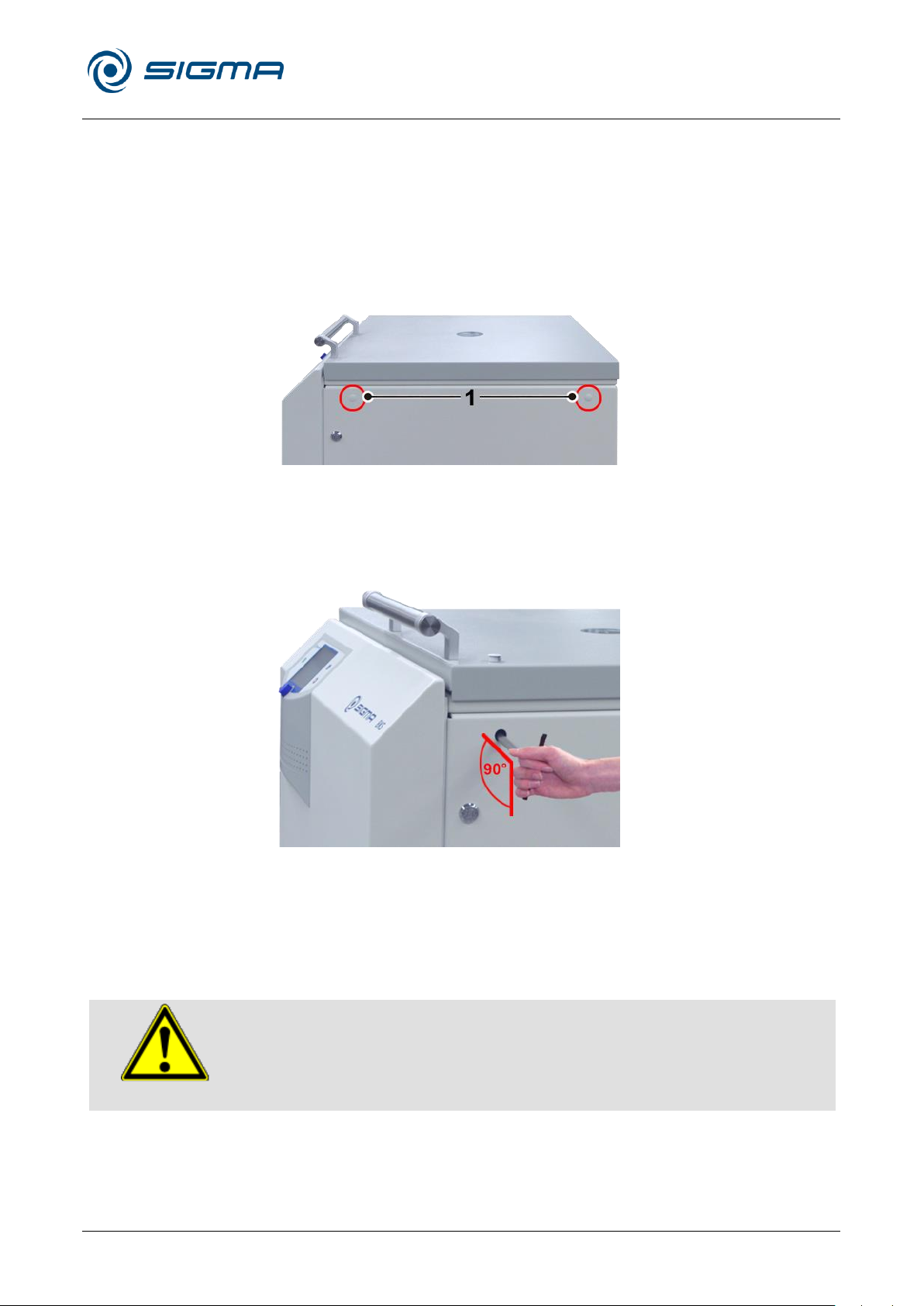
Refrigerated Centrifuge Sigma 8KS
Refrigerated Centrifuge Sigma 8KBS
7 Malfunctions and error correction
Version 08/2012, Rev. 2.5 of 02/07/2018 • sb
71 / 131
Translation of the original operating manual, part no. 0702502
WARNING
The lid may only be unlocked and opened when the rotor is at a standstill.
Pos: 193 /100 Sigma/110 BA Zentrifugen Sig ma (Projekte)/8KS_8KBS_8KHBS/ 070 Störungen und Fehlersuche/070-0 010-0011 Notentriegelung des Dec kels - flacher Deckel @ 46\mod_148153726 0198_68.docx @ 461692 @ 3 @ 1
7.1.1 Emergency lid release
In the event of a power failure, it is possible to manually open the centrifuge
lid.
• Switch off the mains power switch and disconnect the power cord from
the socket.
• Remove the plugs (see figure, item 1) at the right side panel, e.g. with a
screw driver.
Fig. 43: Position of the openings for the emergency lid release
• Insert the supplied tube wrench (part no. 930 110) horizontally into the
hole. The key will be guided through a funnel-shaped tube to the shaft
of the lid lock motor.
Fig. 44: The emergency lid release key must be inserted horizontally.
• Unlock the motorised lid locks as follows:
– Turn the left lid lock anti-clockwise.
– Turn the right lid lock clockwise.
• Then, reinsert the plugs.
If the lid is opened via the emergency lid release system during a centrifuge
run, the centrifuge will be switched off immediately and decelerate in an
Pos: 194 /010 Universalmodule/Seiten wechsel @ 0\mod_1202116244312_0.d ocx @ 105 @ @ 1
unbraked manner.
Page 72

Refrigerated Centrifuge Sigma 8KS
Refrigerated Centrifuge Sigma 8KBS
7 Malfunctions and error correction
72 / 131
Version 08/2012, Rev. 2.5 of 02/07/2018 • sb
Translation of the original operating manual, part no. 0702502
Error no.
Kind of error
Measures
Note
1-9
System error
• Allow to slow down
• Power off/on
All these errors stop the
centrifuge or cause it to
decelerate brakeless
10-19
Speedometer error
• Allow to slow down
• Power off/on
20-29
Motor error
• Power off
• Ensure ventilation
30-39
EEPROM error
• Allow to slow down
• Power off/on
With error 34, 35, and 36, the
centrifuge will stop;
with error 37 and 38 only an
error message will be given
40-45
Temperature error
(only for refrigerated centrifuges)
• Allow to slow down
• Power off
• Allow to cool down
• Provide better ventilation (only
air cooled centrifuges)
• Provide sufficient water
throughput (only water cooled
centrifuges)
46-49
Imbalance error (only for centrifuges
with imbalance monitoring system)
• Allow to slow down
• Power off
• Eliminate the imbalance
50-59
Lid error
• Press lid key
• Close lid
• Remove foreign matter from
the opening of the lid lock
device
With error 50 and 51, the
centrifuge will stop
60-69
Process error
• Allow to slow down
• Power off/on
With error 60, the message
"power failure during run"will
be displayed, with error 61,
the message "stop after
power on" will be displayed
70-79
Communication error
• Allow to slow down
• Power off/on
80-89
Parameter error
• Power off
• Allow to cool down
• Provide for better ventilation
With error 83, error message
only
90-99
Other errors
• Check connections
• Provide sufficient water
throughput (only water cooled
centrifuges)
NOTE
If it is impossible to eliminate the errors, contact the service!
Pos: 195 /100 Sigma/100 BA Zentrifugen Sig ma (Standardmodule)/070 Störungen u nd Fehlersuche/070-0020 Tabell e der Fehlermeldungen @ 28\mod_14 05320582996_68.docx @ 194761 @ 2 @ 1
7.2 Table of error codes
Pos: 196 /010 Universalmodule/Seiten wechsel @ 0\mod_1202116244312_0.d ocx @ 105 @ @ 1
Page 73

Refrigerated Centrifuge Sigma 8KS
Refrigerated Centrifuge Sigma 8KBS
7 Malfunctions and error correction
Version 08/2012, Rev. 2.5 of 02/07/2018 • sb
73 / 131
Translation of the original operating manual, part no. 0702502
NOTE
• If you would like to utilise our service, please state the type of your
centrifuge and its serial number.
Pos: 197 /100 Sigma/100 BA Zentrifugen Sig ma (Standardmodule)/070 Störungen u nd Fehlersuche/070-0030 Konta kt im Servicefall @ 28\mod_1405320584 361_68.docx @ 194775 @ 2 @ 1
7.3 Service contact
In the event of queries, malfunctions, or spare part enquiries:
From Germany:
Contact
Sigma Laborzentrifugen GmbH
An der Unteren Söse 50
37520 Osterode (Germany)
Tel. +49 (0) 55 22 / 50 07-44 44
E-mail: [email protected]
Outside Germany:
Contact our agency in your country. All agencies are listed at
www.sigma-zentrifugen.de [Sales Partners]
Pos: 198 /010 Universalmodule/Abschnitt swechsel @ 0\mod_1202124514062_0. docx @ 418 @ @ 1
Pos: 199 /010 Universalmodule/Seiten wechsel @ 0\mod_1202116244312_0.d ocx @ 105 @ @ 1
Page 74
Refrigerated Centrifuge Sigma 8KS
Refrigerated Centrifuge Sigma 8KBS
8 Maintenance and service
74 / 131
Version 08/2012, Rev. 2.5 of 02/07/2018 • sb
Translation of the original operating manual, part no. 0702502
CAUTION
If corrosion or other damage occurs due to improper care, the
manufacturer cannot be held liable or subject to any warranty claims.
WARNING
Take suitable precautions for your own safety if there is a risk of toxic,
radioactive, or pathogenic contamination.
Pos: 200 /100 Sigma/100 BA Zentrifugen Sig ma (Standardmodule)/080 Wartung u nd Instandhaltung/080 Wartung und Inst andhaltung========================= @ 28\mod_1405320612731_68.docx @ 194789 @ 1 @ 1
8 Maintenance and service
The centrifuge, rotor, and accessories are subject to high mechanical
stress. Thorough maintenance performed by the user extends the service
Pos: 201 /010 Universalmodule/ Leerzeile @ 0\mod_1202116244500_0.docx @ 1 14 @ @ 1
Pos: 202 /100 Sigma/100 BA Zentrifugen Sig ma (Standardmodule)/080 Wartung u nd Instandhaltung/080-0010 Wartung sarbeiten--------------------------------------- @ 28\mod _1405320613978_68.docx @ 194803 @ 2 @ 1
life and prevents premature failure.
• Use soap water or other water-soluble, mild cleaning agents with a pH
value between 6 and 8 for cleaning the centrifuge and accessories (see
also chapter 8.2 - "Sterilisation and disinfection of the rotor chamber
and accessories").
• Avoid corrosive and aggressive substances.
• Do not use solvents.
• Do not use agents with abrasive particles.
• Do not expose the centrifuge and rotors to intensive UV radiation or
thermal stress (e.g. by heat generators).
8.1 Maintenance
Pos: 203 /100 Sigma/100 BA Zentrifugen Sig ma (Standardmodule)/080 Wartung u nd Instandhaltung/080-0010-0010 Zentrifuge @ 28\mod_1405320615295_6 8.docx @ 194817 @ 3 @ 1
8.1.1 Centrifuge
Pos: 204 /010 Universalmodule/Seiten wechsel @ 0\mod_1202116244312_0.d ocx @ 105 @ @ 1
• Unplug the mains power plug before cleaning.
• Carefully remove all liquids, including water and particularly all the
solvents, acids, and alkaline solutions from the rotor chamber using a
cloth in order to avoid damage to the motor bearings.
• If the centrifuge has been contaminated with toxic, radioactive, or
pathogenic substances, clean the rotor chamber immediately with a
suitable decontamination agent (depending on the type of
contamination).
• After every cleaning process, grease the motor shaft slightly with a
small amount of heavy-duty grease for load-bearing bolts (part no.
71401) and distribute the grease with a cloth so that it forms a thin
layer.
Page 75
Refrigerated Centrifuge Sigma 8KS
Refrigerated Centrifuge Sigma 8KBS
8 Maintenance and service
Version 08/2012, Rev. 2.5 of 02/07/2018 • sb
75 / 131
Translation of the original operating manual, part no. 0702502
CAUTION
For the care of the accessories, special safety measures must be
considered as these are measures that will ensure operational safety at
the same time!
WARNING
All swing-out rotors applicable for this centrifuge and the angle rotor 12510
weigh more than 18 kg.
• Always lift the rotors with a lifting device or with a sufficient number of
people helping you.
CAUTION
Do not clean the accessories in a dishwasher!
Cleaning in a dishwasher removes the anodised coating; the result is
cracking in areas that are subject to stress.
Pos: 205 /100 Sigma/100 BA Zentrifugen Sig ma (Standardmodule)/080 Wartung u nd Instandhaltung/080-0010-0010-0 010 Kondensator @ 28\mod_1405320 616708_68.docx @ 194831 @ 4 @ 1
8.1.1.1 Condenser (only refrigerated centrifuges with an air-cooled refrigeration system)
In order to cool the refrigerant that is compressed by the refrigeration unit,
centrifuges with an air-cooled refrigeration system use a lamellar
condenser. It is cooled by air.
Dust and dirt obstruct the cooling flow of air. The dust on condenser pipes
and lamellas reduces the heat exchange and thus the performance of the
refrigeration unit.
This is why the installation site should be as clean as possible.
• Check the condenser at least once a month for dirt and clean it if
necessary.
• If you have any queries, please contact service (see chapter 7.3 -
Pos: 206 /010 Universalmodule/ Leerzeile @ 0\mod_1202116244500_0.docx @ 1 14 @ @ 1
Pos: 207 /100 Sigma/110 BA Zentrifugen Sigma (Projekte)/8KS_8KBS_8KHBS/ 080 Wartung und Instandhaltung/080- 0010-0020 Zubehör @ 29\mod_1405 327472057_68.docx @ 199913 @ 3 @ 1
8.1.2 Accessories
"Service contact").
• Immediately rinse off the rotor, buckets, or accessories under running
water if they have come into contact with any liquids that may cause
corrosion. Use a brush for test tubes to clean the bores of angle rotors.
Turn the rotor upside down and allow it to dry completely.
• Clean the accessories outside the centrifuge once a week or preferably
after each use. Adapters should be removed, cleaned and dried.
• If the rotors or accessories have been contaminated with toxic,
radioactive, or pathogenic substances, clean them immediately with a
suitable decontamination agent (depending on the type of
contamination). Take suitable precautions for your own safety if there is
a risk of toxic, radioactive, or pathogenic contamination.
• Dry the accessories with a soft cloth or in a drying chamber at
Pos: 208 /010 Universalmodule/Seiten wechsel @ 0\mod_1202116244312_0.d ocx @ 105 @ @ 1
approx. 50°C.
Page 76

Refrigerated Centrifuge Sigma 8KS
Refrigerated Centrifuge Sigma 8KBS
8 Maintenance and service
76 / 131
Version 08/2012, Rev. 2.5 of 02/07/2018 • sb
Translation of the original operating manual, part no. 0702502
WARNING
Plastic accessories must not be greased!
Pos: 209 /100 Sigma/100 BA Zentrifugen Sig ma (Standardmodule)/080 Wartung u nd Instandhaltung/080-0010-0020-0 010 Kunststoffzubehör @ 28\mod_1405 320619602_68.docx @ 194859 @ 4 @ 1
8.1.2.1 Plastic accessories
The chemical resistance of plastic decreases with rising temperatures (see
chapter 11.5 - "Resistance data").
• If solvents, acids, or alkaline solutions have been used, clean the plastic
Pos: 210 /010 Universalmodule/ Leerzeile @ 0\mod_1202116244500_0.docx @ 1 14 @ @ 1
Pos: 211 /100 Sigma/100 BA Zentrifugen Sig ma (Standardmodule)/080 Wartung u nd Instandhaltung/080-0010-0030 Rotor, Becher und Vielfachträger (außer Basic) @ 28\mod_1405320621063_68. docx @ 194873 @ 3 @ 1
accessories thoroughly.
8.1.3 Rotors, buckets and carriers
Rotors, buckets and carriers are produced with the highest precision, in
order to withstand the permanent high stress from high gravitational fields.
Chemical reactions as well as stress-corrosion (combination of oscillating
pressure and chemical reaction) can affect or destroy the metals. Barely
detectable cracks on the surface can expand and weaken the material
without any visible signs.
• Check the material regularly (at least once a month) for
– cracks
– visible damage of the surface
– pressure marks
– signs of corrosion
– other changes.
• Check the bores of the rotors and multiple carriers.
• Replace any damaged components immediately for your own safety.
• After every cleaning process, grease the rotor tie-down screw slightly
with a small amount of heavy-duty grease for load-bearing bolts (part
no. 71401) and distribute the grease with a cloth so that it forms a thin
Pos: 212 /010 Universalmodule/Seiten wechsel @ 0\mod_1202116244312_0.d ocx @ 105 @ @ 1
layer.
Page 77
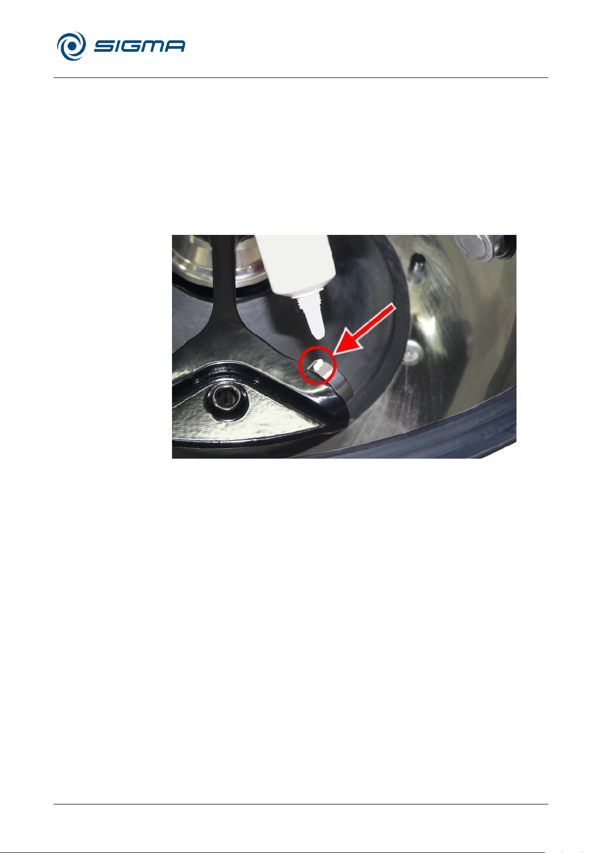
Refrigerated Centrifuge Sigma 8KS
Refrigerated Centrifuge Sigma 8KBS
8 Maintenance and service
Version 08/2012, Rev. 2.5 of 02/07/2018 • sb
77 / 131
Translation of the original operating manual, part no. 0702502
Pos: 213 /100 Sigma/100 BA Zentrifugen Sig ma (Standardmodule)/080 Wartung u nd Instandhaltung/080-0010-0040 Tragbolzen (außer 2-6, 2-6E, 2-7, 2-1 6P, 2-16KL) @ 28\mod_1405320624792_ 68.docx @ 194915 @ 3 @ 1
8.1.4 Load bearing bolts
Only greased load-bearing bolts ensure a uniform swing-out of the buckets
and, therefore, the smooth operation of the centrifuge. Load-bearing bolts
that are insufficiently greased may cause the centrifuge to stop due to an
imbalance.
• Clean the load-bearing bolts and bucket groove in order to remove the
old grease.
• Apply a small amount of heavy-duty grease for load-bearing bolts (ref.
no. 71401, see the following picture) to both load-bearing bolts of a
bucket.
Fig. 45: Sufficient quantity of grease for one bolt
• Install the bucket and swing it manually back and forth once in order to
distribute the grease.
Pos: 214 /010 Universalmodule/Seiten wechsel @ 0\mod_1202116244312_0.d ocx @ 105 @ @ 1
• Repeat this process with all the other buckets.
Page 78

Refrigerated Centrifuge Sigma 8KS
Refrigerated Centrifuge Sigma 8KBS
8 Maintenance and service
78 / 131
Version 08/2012, Rev. 2.5 of 02/07/2018 • sb
Translation of the original operating manual, part no. 0702502
CAUTION
In the case of glass breakage, immediately remove all glass particles (e.g.
with a vacuum cleaner). Replace the rubber cushions since even thorough
cleaning will not remove all glass particles.
DANGER
If dangerous materials (e.g. infectious and pathogenic substances) are
used, the centrifuge and accessories must be disinfected.
Pos: 215 /100 Sigma/100 BA Zentrifugen Sig ma (Standardmodule)/080 Wartung u nd Instandhaltung/080-0010-0060 Glasbruch @ 28\mod_1405320623434_ 68.docx @ 194901 @ 3 @ 1
8.1.5 Glass breakage
Glass particles will damage the surface coating (e.g. anodising) of the
buckets, which will then lead to corrosion.
Glass particles in the rubber cushions of the buckets will cause glass
breakage again.
Glass particles on the pivot bearing of the load- bearing bolts prevent the
buckets and carriers from swinging evenly, which will cause an imbalance.
Glass particles in the rotor chamber will cause metal abrasion due to the
strong air circulation. This metal dust will not only pollute the rotor chamber,
rotor, and materials to be centrifuged but also damage the surfaces of the
accessories, rotors, and rotor chamber.
In order to completely remove the glass particles and metal dust from
the rotor chamber:
• Grease the upper third of the rotor chamber with e.g. Vaseline.
• Then, let the rotor rotate for a few minutes at a moderate speed
• Remove the grease with the glass and metal particles with a cloth.
Pos: 216 /010 Universalmodule/ Leerzeile @ 0\mod_1202116244500_0.docx @ 1 14 @ @ 1
Pos: 217 /100 Sigma/100 BA Zentrifugen Sig ma (Standardmodule)/080 Wartung u nd Instandhaltung/080-0020 Steril isation und Desinfektion von Rotorkam mer und Zubehör @ 28\mod_140532062 6090_68.docx @ 194929 @ 2 @ 1
• If necessary, repeat this procedure.
(approx. 2000 rpm). The glass and metal particles will now collect at the
greased part.
8.2 Sterilisation and disinfection of the rotor chamber and
accessories
• Use commercially-available disinfectants such as, for example,
Sagrotan, Buraton, or Terralin (available at chemist’s shops or
drugstores).
• The centrifuge and the accessories consist of various materials. A
possible incompatibility must be considered.
• Before using cleaning or decontamination agents that were not
recommended by us, contact the manufacturer to ensure that such a
procedure will not damage the centrifuge.
• For autoclaving, consider the continuous heat resistance of the
individual materials (see chapter 8.2.1 - "Autoclaving").
Please contact us if you have any queries (see chapter 7.3 - "Service
Pos: 218 /010 Universalmodule/Seiten wechsel @ 0\mod_1202116244312_0.d ocx @ 105 @ @ 1
contact").
Page 79

Refrigerated Centrifuge Sigma 8KS
Refrigerated Centrifuge Sigma 8KBS
8 Maintenance and service
Version 08/2012, Rev. 2.5 of 02/07/2018 • sb
79 / 131
Translation of the original operating manual, part no. 0702502
NOTE
It cannot be excluded that plastic parts, e.g. lids or carriers, may deform
during autoclaving.
Accessories
Max. temp.
(°C)
Min. time
(min)
Max. time
(min)
Max. cycles
Aluminium buckets
134-138
3 5 -
Aluminium rotors
134-138
3 5 -
Glass tubes
134-138
3
40
-
Polyallomer / polycarbonate rectangular carriers
115-118
30
40
-
Polyallomer / polycarbonate round carriers
115-118
30
40
-
Polyamide buckets
115-118
30
40
10
Polycarbonate / polyallomer lids for angle rotors
115-118
30
40
20
Polycarbonate tubes
115-118
30
40
20
Polyphenylsulfone (PPSU) caps for buckets
134-138
3 5 100
Polypropylene balance adapter for blood-bag systems
115-118
30
40
n.s.
Polypropylene copolymer tubes
115-121
30
40
20
Polypropylene rectangular carriers
115-118
30
40
-
Polypropylene rotors
115-118
30
40
20
Polypropylene round carriers
115-118
30
40
-
Polysulfone caps for buckets
134-138
3 5 100
Polysulfone lids for angle rotors
134-138
3 5 100
Rubber adapters
115-118
30
40
-
Stainless-steel balance weight for blood-bag systems
121
30
30
n.s.
Teflon tubes
134-138
3 5 100
Pos: 219 /100 Sigma/100 BA Zentrifugen Sig ma (Standardmodule)/080 Wartu ng und Instandhaltung/080-0020-0010 Autoklavieren @ 28\mod_1405320627 440_68.docx @ 194943 @ 3 @ 1
8.2.1 Autoclaving
The service life of the accessories essentially depends on the frequency of
autoclaving and use.
• Replace the accessories immediately when the parts show changes in
colour or structure or in the occurrence of leaks etc.
• During autoclaving, the caps of the tubes must not be screwed on in
order to avoid the deformation of the tubes.
Pos: 220 /010 Universalmodule/Seiten wechsel @ 0\mod_1202116244312_0.d ocx @ 105 @ @ 1
Page 80
Refrigerated Centrifuge Sigma 8KS
Refrigerated Centrifuge Sigma 8KBS
8 Maintenance and service
80 / 131
Version 08/2012, Rev. 2.5 of 02/07/2018 • sb
Translation of the original operating manual, part no. 0702502
DANGER
In the event of service work that requires the removal of the panels, there
is a risk of electric shock or mechanical injury. Only qualified specialist
personnel is authorised to perform this service work.
NOTE
• If you would like to utilise our service, please state the type of your
centrifuge and its serial number.
Pos: 221 /100 Sigma/100 BA Zentrifugen Sig ma (Standardmodule)/080 Wartung u nd Instandhaltung/080-0030 Instan dhaltungsarbeiten @ 28\mod_1405320 628810_68.docx @ 194957 @ 2 @ 1
8.3 Service
The centrifuge is subject to high mechanical stress. In order to be able to
withstand this high level of stress, high-quality components were used
during the production of the centrifuge. Nevertheless, wear cannot be
excluded and it may not be visible from the outside. Especially the rubber
parts that are – among other things – part of the motor suspension, are
subject to ageing.
This is why we recommend having the centrifuge checked by the
manufacturer during an inspection once per year in the operating state and
once every three years in the dismantled state. Rubber parts should be
replaced after three years.
Information and appointments:
In Germany:
Contact
Sigma Laborzentrifugen GmbH
An der Unteren Söse 50
37520 Osterode (Germany)
Tel. +49 (0) 55 22 / 50 07-44 44
E-mail: [email protected]
Outside Germany:
Contact our agency in your country. All agencies are listed at
www.sigma-zentrifugen.de [Sales Partners]
Pos: 222 /010 Universalmodule/Seiten wechsel @ 0\mod_1202116244312_0.d ocx @ 105 @ @ 1
Page 81
Refrigerated Centrifuge Sigma 8KS
Refrigerated Centrifuge Sigma 8KBS
8 Maintenance and service
Version 08/2012, Rev. 2.5 of 02/07/2018 • sb
81 / 131
Translation of the original operating manual, part no. 0702502
NOTE
We will return the part/unit if no declaration of decontamination is provided!
NOTE
If the form does not include a description of the malfunction, neither a
refund nor a credit note can be issued. In this case, we reserve the right to
return the part/unit to you at your expense.
Pos: 223 /100 Sigma/100 BA Zentrifugen Sig ma (Standardmodule)/080 Wartung und Instandhaltung/080-0040 Rüc ksendung defekter Teile @ 28\mod_1405 320630226_68.docx @ 194971 @ 2 @ 1
8.4 Return of defective centrifuges or parts
Although we exercise great care during the production of our products, it
may be necessary to return a unit or accessory to the manufacturer.
In order to ensure the quick and economical processing of returns of
centrifuges, spare parts, or accessories, we require complete and extensive
information concerning the process. Please fill in the following forms
completely, sign them, enclose them with the return package, and send
them together with the product to:
Sigma Laborzentrifugen GmbH
An der Unteren Söse 50
37520 Osterode (Germany)
1. Declaration of decontamination
As a certified company and due to the legal regulations for the
protection of our employees and of the environment, we are obliged to
certify the harmlessness of all incoming goods. For this purpose, we
require a declaration of decontamination.
• The form must be filled in completely and signed by authorised and
specialised personnel only.
• Affix the original form in a clearly visible manner to the outside of the
packaging.
2. Form for the return of defective parts
This form is for the product-related data. They facilitate the assignment,
and they enable the quick processing of the return. If several parts are
returned together in one packaging, please enclose a separate problem
description for every defective part.
• A detailed problem description is necessary in order to perform the
repair quickly and economically.
• Upon request, we will prepare and submit to you a cost estimate
prior to performing the repair. Please confirm such cost estimate
within 14 days. If the cost estimate has still not been confirmed after
4 weeks, we will return the defective part/unit. Please note that you
must bear the incurred costs.
Page 82

Refrigerated Centrifuge Sigma 8KS
Refrigerated Centrifuge Sigma 8KBS
8 Maintenance and service
82 / 131
Version 08/2012, Rev. 2.5 of 02/07/2018 • sb
Translation of the original operating manual, part no. 0702502
NOTE
The defective part/unit must be packaged in a transport-safe manner.
Please use the original packaging for the unit, if at all possible.
If the product is dispatched to us in unsuitable packaging, you will be
charged the cost for returning it to you in new packaging.
The forms can be downloaded online from
Pos: 224 /010 Universalmodule/Abschnitt swechsel @ 0\mod_1202124514062_0. docx @ 418 @ @ 1
Pos: 225 /010 Universalmodule/Seiten wechsel @ 0\mod_1202116244312_0.d ocx @ 105 @ @ 1
www.sigma-zentrifugen.de [Service] [Overhaul and repair].
Page 83

Refrigerated Centrifuge Sigma 8KS
Refrigerated Centrifuge Sigma 8KBS
9 Disposal
Version 08/2012, Rev. 2.5 of 02/07/2018 • sb
83 / 131
Translation of the original operating manual, part no. 0702502
In accordance with the directive 2002/96/EC, SIGMA centrifuges are
marked with the symbol shown to the left. This symbol means that it is not
permissible to dispose of the unit among household waste.
• You can return these centrifuges free of cost to
Sigma Laborzentrifugen GmbH.
• Ensure that the unit is decontaminated. Fill in a declaration of
decontamination (see chapter 8.4 - "Return of defective centrifuges or
parts").
• Comply with any other applicable local rules and regulations.
Pos: 226 /100 Sigma/100 BA Zentrifugen Sig ma (Standardmodule)/090 Entsorgu ng/090 Entsorgung========= ============================ @ 28\ mod_1405320658842_68.docx @ 194985 @ 1 @ 1
9 Disposal
Pos: 227 /100 Sigma/100 BA Zentrifugen Sig ma (Standardmodule)/090 Entsorgung/ 090-0010 Entsorgung der Zentrif uge---------------------------------------------- @ 28\mod_1405320660029_68.docx @ 194999 @ 2 @ 1
9.1 Disposal of the centrifuge
Pos: 228 /010 Universalmodule/ Leerzeile @ 0\mod_1202116244500_0.docx @ 1 14 @ @ 1
Pos: 229 /100 Sigma/100 BA Zentrifugen Sig ma (Standardmodule)/090 Entsorgung/ 090-0020 Entsorgung der Verp ackung-------------------------------------------------- @ 28\mod_1405320661383_68.docx @ 195013 @ 2 @ 1
9.2 Disposal of the packaging
• Use the packaging to return the centrifuge for disposal or
• dispose of the packaging, after having separated the individual
materials.
Pos: 230 /010 Universalmodule/Abschnitt swechsel @ 0\mod_1202124514062_0. docx @ 418 @ @ 1
Pos: 231 /010 Universalmodule/Seiten wechsel @ 0\mod_1202116244312_0.d ocx @ 105 @ @ 1
• Comply with all local rules and regulations.
Page 84
Refrigerated Centrifuge Sigma 8KS
Refrigerated Centrifuge Sigma 8KBS
10 Technical data
84 / 131
Version 08/2012, Rev. 2.5 of 02/07/2018 • sb
Translation of the original operating manual, part no. 0702502
Manufacturer
SIGMA Laborzentrifugen GmbH
An der Unteren Söse 50
37520 Osterode (Germany)
Type:
8KS
8KBS
Connection requirements
Electr. connection:
Protection class:
IP code:
see name plate
I
20
see name plate
I
20
Connected load (kVA):
Power consumption (kW):
Max. current consumption (A):
Input fuse (AT):
7.5
6.5
11.5 (at 3x400V / 50 Hz)
16.0
7.5
6.5
11.5 (at 3x400V / 50 Hz)
16.0
Performance data
Max. speed (rpm):
Max. capacity (ml):
Max. gravitational field (x g):
Max. kin. energy (Nm):
10,500
12,000
20,954
280,080
5,100
12,000
8,578
280,080
Other parameters
Time range:
Temperature range:
Storage locations:
10 sec to 99 h 59 min 59 sec,
short run, continuous run
-20 to +40°C
60
10 sec to 99 h 59 min 59 sec
short run, continuous run
-20 to +40°C
60
Physical data
Height (mm):
Height with open lid (mm):
Width (mm):
Depth (mm):
Weight (kg):
Noise level (dB(A)):
990
1,679
810
945
450
< 73 (at maximum speed)
990
1,679
810
945
450
< 73 (at maximum speed)
Refrigerant data
Refrigerant:
Filling quantity (kg):
Pressure (bar):
CO2 equivalent (t):
R404A
2.280
25
8.942
R404A
2.280
25
8.942
Special equipment:
Water cooling system
Tap connections (inch):
Inlet pressure (bar):
Min. flow rate (l/min):
Max. temperature at water inlet (°C):
2 x ¾
1.5 to 5.0
5 (at maximum power)
20
2 x ¾
1.5 to 5.0
5 (at maximum power)
20
Pos: 232 /100 Sigma/100 BA Zentrifugen Sig ma (Standardmodule)/100 Technisch e Daten/100 Technische Daten - Ü berschrift ================== =========== @ 7\mod_1306745782782_6 8.docx @ 43932 @ 1 @ 1
10 Technical data
Pos: 233 /100 Sigma/110 BA Zentrifug en Sigma (Projekte)/8KS_8KBS_8KHBS/ 100 Technische Daten/101 Technische Daten 8KS_8KBS flacher Deckel - Te xt ====================== ======= @ 46\mod_1481610951303_68.doc x @ 461768 @ @ 1
Pos: 234 /010 Universalmodule/Seiten wechsel @ 0\mod_1202116244312_0.d ocx @ 105 @ @ 1
Page 85

Refrigerated Centrifuge Sigma 8KS
Refrigerated Centrifuge Sigma 8KBS
10 Technical data
Version 08/2012, Rev. 2.5 of 02/07/2018 • sb
85 / 131
Translation of the original operating manual, part no. 0702502
Pos: 235 /100 Sigma/110 BA Zentrifugen Sig ma (Projekte)/8KS_8KBS_8KHBS/10 0 Technische Daten/102-0010 Umge bungsbedingungen 8KS_8KBS @ 2 9\mod_1405327490293_68.docx @ 19994 1 @ 2 @ 1
10.1 Ambient conditions
• The figures are valid for an ambient temperature of +23°C and a
nominal voltage 10 %. The minimum temperature is ≤ +4°C and
depends on the rotor type, speed, and ambient temperature.
• For indoor use only.
• Allowable ambient temperature +5°C to +35°C.
• Max. relative humidity of air 80% up to 31°C with a linear decrease to
67% relative humidity of air at 35°C.
Pos: 236 /010 Universalmodule/ Leerzeile @ 0\mod_1202116244500_0.docx @ 1 14 @ @ 1
Pos: 237 /100 Sigma/100 BA Zentrifugen Sig ma (Standardmodule)/100 Tec hnische Daten/100-0020 Technische Doku mentation @ 28\mod_1405320681369_ 68.docx @ 195055 @ 2 @ 1
• Maximum altitude 2,000 m above sea level.
10.2 Technical documentation
For environmental reasons, the comprehensive technical documentation of
the centrifuge (e.g. circuit diagrams) and the safety data sheets of the
manufacturers of refrigerants and lubricants are not attached to this
documentation.
Pos: 238 /010 Universalmodule/Abschnitt swechsel @ 0\mod_1202124514062_ 0.docx @ 418 @ @ 1
Pos: 239 /010 Universalmodule/Seiten wechsel @ 0\mod_1202116244312_0.d ocx @ 105 @ @ 1
You can order these documents from our service department.
Page 86
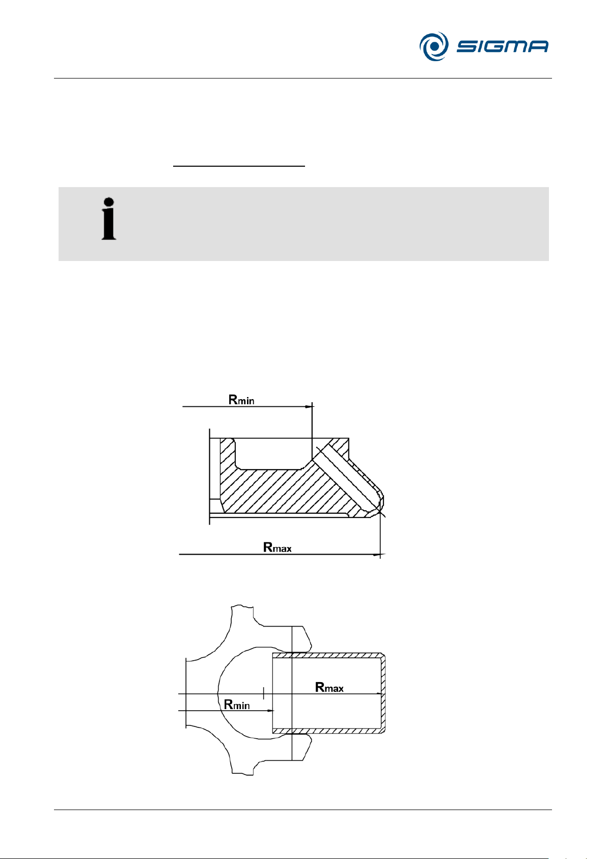
Refrigerated Centrifuge Sigma 8KS
Refrigerated Centrifuge Sigma 8KBS
11 Appendix
86 / 131
Version 08/2012, Rev. 2.5 of 02/07/2018 • sb
Translation of the original operating manual, part no. 0702502
NOTE
If the swing-out rotor 11805 with a windshield is used in combination with
the blood bag bucket 13860, it can also be used without the windshield
cover.
For all other rotor-bucket-combinations, the windshield must be closed.
Pos: 240 /100 Sigma/100 BA Zentrifugen Sig ma (Standardmodule)/110 Anhang/ 110 Anhang============== ======================= @ 28\mo d_1405320699310_68.docx @ 195069 @ 1 @ 1
11 Appendix
Pos: 241 /100 Sigma/110 BA Zentrifugen Sig ma (Projekte)/8KS_8KBS_8KHBS/11 0 Anhang/110-0010 Zubehörprogr amm 8KS_8KBS - ohne Tabelle @ 56\ mod_1523441520854_68.docx @ 56055 6 @ 2 @ 1
11.1 Range of accessories
The complete list of accessories can be downloaded from
www.sigma-zentrifugen.de.
Pos: 242 /010 Universalmodule/ Leerzeile @ 0\mod_1202116244500_0.docx @ 1 14 @ @ 1
Pos: 243 /010 Universalmodule/ Leerzeile @ 0\mod_1202116244500_0.docx @ 1 14 @ @ 1
Pos: 244 /100 Sigma/100 BA Zentrifugen Sig ma (Standardmodule)/110 Anhang/ 110-0010-0020 Radien der Rotoren ( WR+AR) @ 28\mod_1405320700923_6 8.docx @ 195083 @ 3 @ 1
11.1.1 Rotor radii
The information in the accessories table concerning the radius refers to the
values of the respective rotor as shown below. The radius calculation is
described in chapter 2.2.2.1 - "Speed, radius, and relative centrifugal
force".
Fig. 46: Minimum and maximum radius of an angle rotor
Pos: 245 /010 Universalmodule/Seiten wechsel @ 0\mod_1202116244312_0.d ocx @ 105 @ @ 1
Fig. 47: Minimum and maximum radius of a swing-out rotor
Page 87
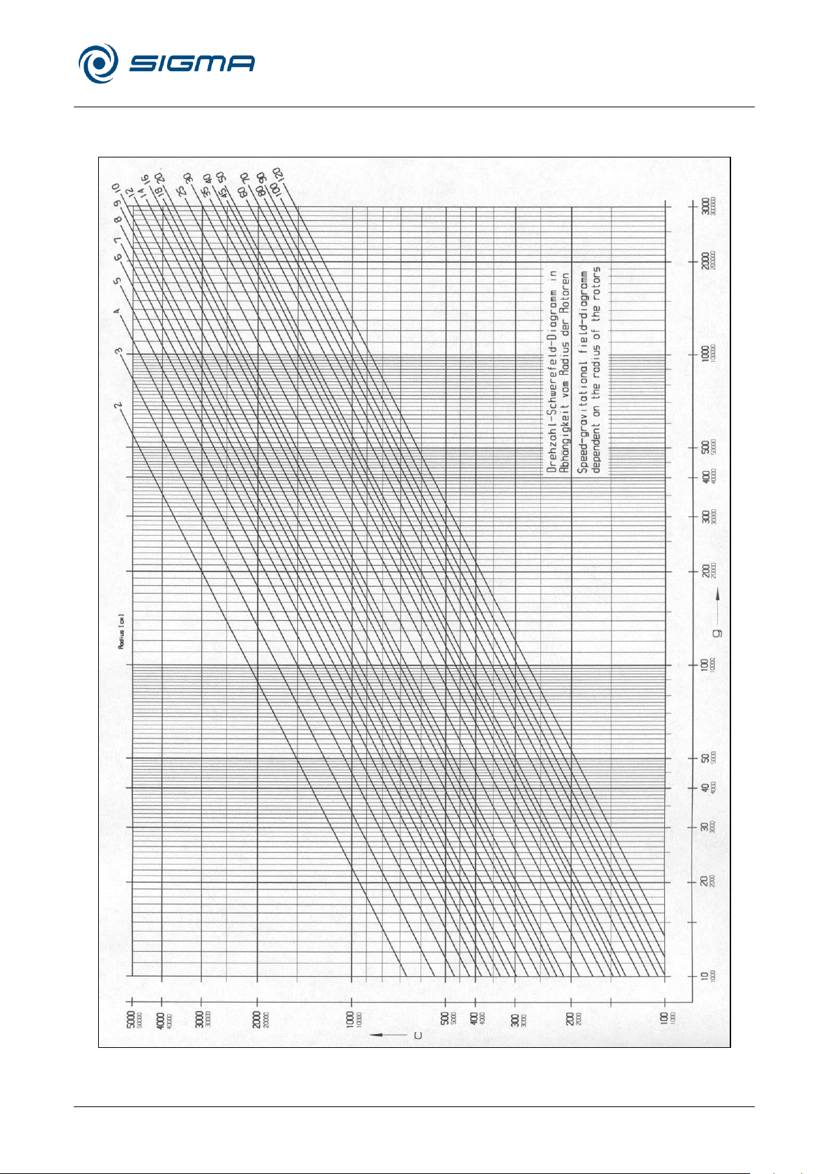
Refrigerated Centrifuge Sigma 8KS
Refrigerated Centrifuge Sigma 8KBS
11 Appendix
Version 08/2012, Rev. 2.5 of 02/07/2018 • sb
87 / 131
Translation of the original operating manual, part no. 0702502
Pos: 246 /100 Sigma/100 BA Zentrifugen Sig ma (Standardmodule)/110 Anhang/ 110-0020 Drehzahl-Schwerefeld-Diagr amm @ 28\mod_1405320705642_68.d ocx @ 195153 @ 2 @ 1
11.2 Speed-gravitational-field-diagram
Fig. 48: Speed-gravitational-field-diagram
Pos: 247 /010 Universalmodule/Seiten wechsel @ 0\mod_1202116244312_0.d ocx @ 105 @ @ 1
Page 88

Refrigerated Centrifuge Sigma 8KS
Refrigerated Centrifuge Sigma 8KBS
11 Appendix
88 / 131
Version 08/2012, Rev. 2.5 of 02/07/2018 • sb
Translation of the original operating manual, part no. 0702502
Linear curve no.
Slop
0
4 [rpm/sec]
1
6 [rpm/sec]
2
8 [rpm/sec]
3
17 [rpm/sec]
4
25 [rpm/sec]
5
33 [rpm/sec]
6
50 [rpm/sec]
7
100 [rpm/sec]
8
200 [rpm/sec]
9
1.000 [rpm/sec]
Quadratic curve no.
Time until 1,000 rpm
Slope as of 1,000 rpm
10
500 sec
4 [rpm/sec]
11
333 sec
6 [rpm/sec]
12
250 sec
8 [rpm/sec]
13
118 sec
17 [rpm/sec]
14
80 sec
25 [rpm/sec]
15
60 sec
33 [rpm/sec]
16
40 sec
50 [rpm/sec]
17
20 sec
100 [rpm/sec]
18
10 sec
200 [rpm/sec]
19
2 sec
1.000 [rpm/sec]
Pos: 248 /100 Sigma/100 BA Zentrifugen Sig ma (Standardmodule)/110 Anhang/ 110-0031 Beschleunigungs- und Bre mskurven Spincontrol S @ 28\mod_140 5320708834_68.docx @ 195181 @ 2 @ 1
11.3 Acceleration and deceleration curves
Linear as well as quadratic curves are numbered in the direction of
increasing acceleration (from right to left).
The deceleration curves are inverted images of the acceleration curves and
are assigned the same numbers. An exception is curve 0. It decelerates
brakeless (spin-out).
In general, the runtime, until the set speed is reached, depends on the
moment of inertia of the rotor.
Linear curves
The slope of the fixed acceleration curves defines the time that is required
to accelerate the rotor by 1,000 rpm.
Curve 9 is a special case compared to the other curves. The centrifuge
accelerates with maximum power. The runtime, until the set speed is
reached, depends solely on the moment of inertia of the rotor.
Fig. 49: Slope of linear curves
Quadratic curves
Curve 19 is a special case compared to the other curves. The centrifuge
accelerates with maximum power. The runtime depends solely on the
moment of inertia of the rotor.
Fig. 50: Slope of quadratic curves
Page 89
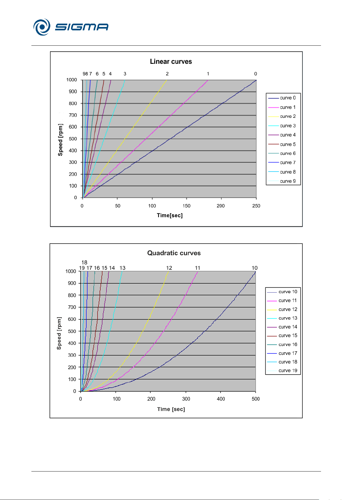
Refrigerated Centrifuge Sigma 8KS
Refrigerated Centrifuge Sigma 8KBS
11 Appendix
Version 08/2012, Rev. 2.5 of 02/07/2018 • sb
89 / 131
Translation of the original operating manual, part no. 0702502
Fig. 51: Diagram of linear curves
Fig. 52: Diagram of quadratic curves
Pos: 249 /010 Universalmodule/Seiten wechsel @ 0\mod_1202116244312_0.d ocx @ 105 @ @ 1
Page 90
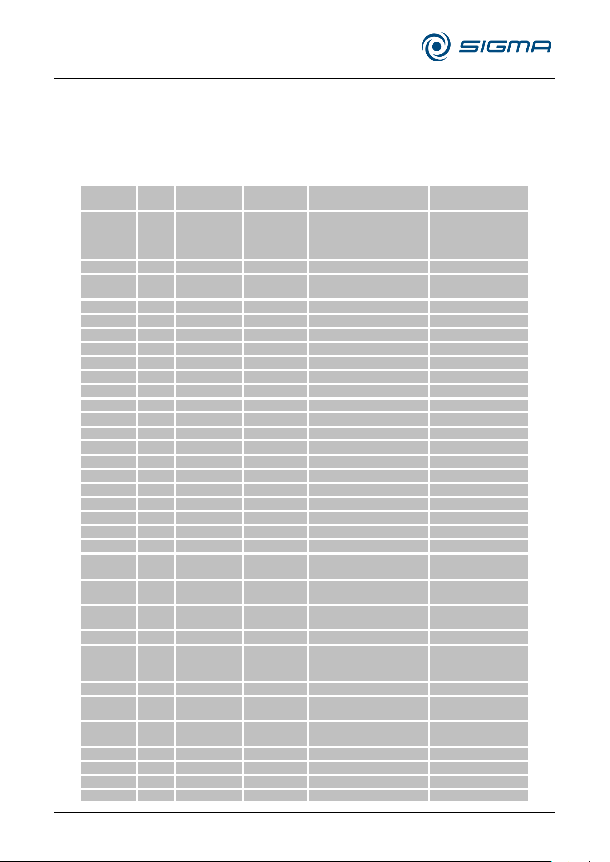
Refrigerated Centrifuge Sigma 8KS
Refrigerated Centrifuge Sigma 8KBS
11 Appendix
90 / 131
Version 08/2012, Rev. 2.5 of 02/07/2018 • sb
Translation of the original operating manual, part no. 0702502
Rotor /
bucket
Cycles
Service life
("Exp.Date")
Autoclaving Suitable for centrifuge Remarks
9100 15,000
4-15C, 4K15C, 4-16, 4-16S,
4-16K, 4-16KS, 6-15, 6K15,
6-16, 6-16K
without engraving, only
"spincontrol
professional" and
"spincontrol S"
11026 7 years
1-14, 1-14K
11805 10 years*
8K, 8KB, 8KS, 8KBS
*in combination with
bucket 13850 or 13860
12033 5 years
1-16 Edition, 1-16K Edition
12082 7 years
1-14, 1-14K
12083 7 years
1-14, 1-14K
12084 7 years
1-14, 1-14K
12085 7 years
1-14, 1-14K
12092 5 years 20x
1-14, 1-14K
12093 5 years 20x
1-14, 1-14K
12094 5 years 20x
1-14, 1-14K
12096 5 years 20x
1-14, 1-14K
12097 5 years 20x
1-14, 1-14K
12101 5 years 20x
1-15, 1-15K, 1-15P, 1-15PK
12124 5 years 20x
1-15, 1-15K, 1-15P, 1-15PK
12126 5 years 20x
1-15, 1-15K, 1-15P, 1-15PK
12134 5 years 20x
1-16, 1-16K
12135 5 years 20x
1-16, 1-16K
12137 5 years 20x
1-16, 1-16K
12500 7 years
6-15, 6K15, 6-16, 6-16K
12600 7 years
6-16S, 6-16KS
13218 20,000
4-16, 4-16S, 4-16K, 4-16KS,
6-16, 6-16S, 6-16K, 6-16KS
13296 35,000 5 years 10x
2-6, 2-6E, 2-7,
2-16P, 2-16KL, 2-16KHL
13299 5 years 10x
2-6, 2-6E, 2-7,
2-16P, 2-16KL, 2-16KHL
13635 25,000
6-16, 6-16K, 6-16S, 6-16KS
13650 20,000
4-5L, 4-16S, 4-16KS,
4-16KHS, 6-16S, 6-16HS,
6-16KS, 6-16KHS
13845 20,000
8K, 8KB, 8KS, 8KBS
13850 10,000 10 years*
8K, 8KB, 8KS, 8KBS
*in combination with
rotor 11805
13860 15,000 10 years*
8K, 8KB, 8KS, 8KBS
*in combination with
rotor 11805
13864 1,000
8K, 8KB, 8KS, 8KBS without engraving
13865 1,000
8K, 8KB, 8KS, 8KBS without engraving
13866 1,000
8K, 8KB, 8KS, 8KBS without engraving
13867 2,500
8K, 8KB, 8KS, 8KBS without engraving
Pos: 250 /100 Sigma/100 BA Zentrifugen Sig ma (Standardmodule)/110 Anhang/ 110-0040 Tabelle: Lebensdauer vo n Rotoren und Zubehör @ 28\mod_1405 320709911_68.docx @ 195195 @ 2 @ 1
11.4 Table of the service life of rotors and accessories
• If no other data concerning the service life are engraved on the rotor or accessory, rotors and
buckets must be checked by the manufacturer after 10 years.
• If a specification concerning the maximum number of cycles and a specification concerning the
service life (i.e. a date) are provided, the specification that occurs first shall apply.
• After 50,000 cycles, rotors must be scrapped for safety reasons.
Pos: 251 /010 Universalmodule/Seiten wechsel @ 0\mod_1202116244312_0.d ocx @ 105 @ @ 1
Page 91
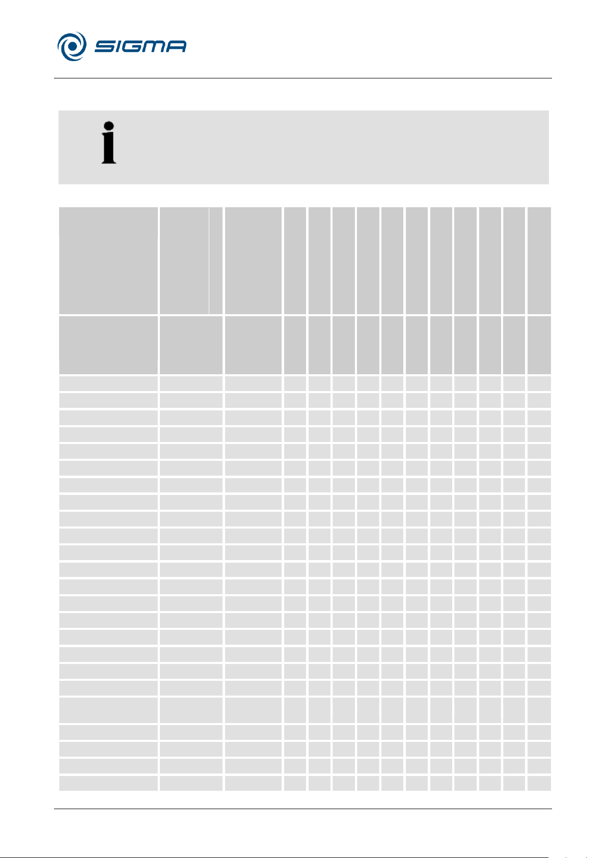
Refrigerated Centrifuge Sigma 8KS
Refrigerated Centrifuge Sigma 8KBS
11 Appendix
Version 08/2012, Rev. 2.5 of 02/07/2018 • sb
91 / 131
Translation of the original operating manual, part no. 0702502
NOTE
The data refer to resistance at 20°C.
- no data
1 resistant
2 practically resistant
3 partially resistant
4 not resistant
Concentration
High Density
Polyethylene
Polyamide
Polycarbonate
Polyoxymethylene
Polypropylene
Polysulfone
Polyvinyl chloride, hard
Polyvinyl chloride, soft
Polytetrafluorethylene
Acrylonitrile-butadiene-
caoutchouc
Aluminium
Medium
Formula
[%]
HDPE
PA
PC
POM
PP
PSU
PVC
PVC
PTFE
NBR
AL
Acetaldehyde
C2H4O
40
3 2 4 2 3 4 4 - 1 4 1
Acetamide
C2H5NO
saturated
1 1 4 1 1 4 4 - 1 - 1
Acetone
C3H6O
100
1 1 4 1 1 4 4 - 1 4 1
Acrylonitrile
C3H3N
100
1 1 4 3 3 4 4 4 1 4 1
Allyl alcohol
C3H6O
96
1 3 3 2 2 2 2 4 1 1 1
Aluminium chloride
AlCl3
saturated
1 3 2 4 1 - 1 - 1 1 4
Aluminium sulfate
Al2(SO4)3
10
1 1 1 3 1 1 1 1 1 1 1
Ammonium chloride
(NH4)Cl
aqueous
1 1 1 2 1 1 1 1 1 1 3
Ammonium hydroxide
NH3 + H2O
30
1 3 4 1 1 2 1 - 1 - 1
Aniline
C6H7N
100
1 3 4 1 2 4 4 4 1 4 1
Anisole
C7H8O
100
3 4 4 1 4 4 2 - 1 4 1
Antimony trichloride
SbCl3
90
1 4 1 4 1 - 1 - 1 - 4
Benzaldehyde
C7H6O
100
1 3 4 1 1 3 4 4 1 4 1
Benzene
C6H6
100
3 2 4 1 3 4 4 - 1 4 1
Boric acid
H3BO3
aqueous
1 3 1 2 1 - - - 1 1 1
Butyl acrylate
C7H12O2
100
1 2 4 2 3 4 4 4 1 - 1
Butyl alcohol, normal
C4H10O
100
1 1 2 1 1 2 2 4 1 1 1
Calcium chloride
CaCl2
alcoholic
1 4 2 3 1 - - 4 1 1 3
Carbon disulfide
CS2
100
4 3 4 2 4 4 4 4 1 3 1
Carbon tetrachloride
(TETRA)
CCl4
100
4 4 4 2 4 4 4 4 1 3 1
Chlorine
Cl2
100
4 4 4 4 4 4 4 4 1 - 3
Chlorine water
Cl2 x H2O
3 4 4 4 3 - 3 3 1 - 4
Chlorobenzene
C6H5Cl
100
3 4 4 1 3 4 4 4 1 4 1
Chloroform
CHCl3
100
3 3 4 4 3 4 4 4 1 4 3
Pos: 252 /100 Sigma/100 BA Zentrifugen Sig ma (Standardmodule)/110 Anhang/ 110-0050 Beständigkeitstabelle @ 28 \mod_1405320711439_68.docx @ 19 5209 @ 2 @ 1
11.5 Resistance data
Page 92

Refrigerated Centrifuge Sigma 8KS
Refrigerated Centrifuge Sigma 8KBS
11 Appendix
92 / 131
Version 08/2012, Rev. 2.5 of 02/07/2018 • sb
Translation of the original operating manual, part no. 0702502
- no data
1 resistant
2 practically resistant
3 partially resistant
4 not resistant
Concentration
High Density
Polyethylene
Polyamide
Polycarbonate
Polyoxymethylene
Polypropylene
Polysulfone
Polyvinyl chloride, hard
Polyvinyl chloride, soft
Polytetrafluorethylene
Acrylonitrile-butadiene-
caoutchouc
Aluminium
Medium
Formula
[%]
HDPE
PA
PC
POM
PP
PSU
PVC
PVC
PTFE
NBR
AL
Chromic acid
CrO3
10
1 4 2 4 1 4 1 - 1 4 1
Chromic potassium
sulphate
KCr(SO4)2 x
12H2O
saturated
1 2 1 3 1 - 1 - 1 - 3
Citric acid
C6H8O7
10
1 1 1 2 1 1 1 1 1 1 1
Citric acid
C6H8O7
50
1 3 1 2 1 - - - 1 1 1
Copper sulphate
CuSO4 x 5H2O
10
1 1 1 1 1 1 1 1 1 1 4
Cyclohexanol
C6H12O
100
1 1 3 1 1 1 1 4 1 2 1
Decane
C10H22
100
- 1 2 1 3 - - - 1 2 1
Diaminoethane
C2H8N2
100
1 1 3 1 1 - 3 4 1 1 1
Diesel fuel — 100
1 1 3 1 1 - 1 3 1 1 1
Dimethyl formamide
(DMF)
C3D7NO
100
1 1 4 1 1 4 3 - 1 3 1
Dimethyl sulfoxide
(DMSO)
C2H6SO
100
1 2 4 1 1 4 4 - 1 - 1
Dimethylaniline
C8H11N
100
- 3 4 2 4 - - - 1 - 1
Dioxane
C4H8O2
100
2 1 4 1 3 2 3 4 1 3 1
Dipropylene glycol
(mono)methyl ether
C4H10O
100
3 1 4 1 4 4 4 4 1 - 1
Ethyl acetate
C4H8O2
100
1 1 4 1 1 4 4 4 1 4 1
Ethylene chloride
C2H4Cl2
100
3 3 4 1 3 4 4 4 1 - 1
Ferrous chloride
FeCl2
saturated
1 3 1 3 1 1 1 1 1 - 4
Formaldehyde solution
CH2O
30
1 3 1 1 1 - - - 1 2 1
Formic acid
CH2O2
100
1 4 3 4 1 3 3 1 1 2 1
Furfural
C5H4O2
100
1 3 3 2 4 - - - 1 4 1
Gasoline
C5H12 - C12H26
100
2 1 3 1 3 3 2 - 1 1 1
Glycerol
C3H8O3
100
1 1 3 1 1 1 1 2 1 1 1
Heptane, normal
C7H16
100
2 1 1 1 2 1 2 4 1 1 1
Hexane, n-
C6H14
100
2 1 2 1 2 1 2 4 1 1 1
Hydrogen chloride
HCl 5 1 4 1 4 1 1 1 - 1 2 4
Hydrogen chloride
HCl
concentrated
1 4 4 4 1 1 2 3 1 4 4
Hydrogen peroxide
H2O2 3 1 3 1 1 1 1 1 - 1 3 3
Hydrogen peroxide
H2O2
30
1 4 1 4 1 1 1 - 1 3 3
Hydrogen sulphide
H2S
10
1 1 1 1 1 1 1 3 1 3 1
Iodine, tincture of
I2 1 4 3 1 1 - 4 4 1 1 1
Page 93

Refrigerated Centrifuge Sigma 8KS
Refrigerated Centrifuge Sigma 8KBS
11 Appendix
Version 08/2012, Rev. 2.5 of 02/07/2018 • sb
93 / 131
Translation of the original operating manual, part no. 0702502
- no data
1 resistant
2 practically resistant
3 partially resistant
4 not resistant
Concentration
High Density
Polyethylene
Polyamide
Polycarbonate
Polyoxymethylene
Polypropylene
Polysulfone
Polyvinyl chloride, hard
Polyvinyl chloride, soft
Polytetrafluorethylene
Acrylonitrile-butadiene-
caoutchouc
Aluminium
Medium
Formula
[%]
HDPE
PA
PC
POM
PP
PSU
PVC
PVC
PTFE
NBR
AL
Isopropyl alcohol
C3H8O
100
1 1 1 1 1 1 1 4 1 - 2
Lactic acid
C3H6O3
3
1 3 1 2 1 1 2 - 1 1 1
Magnesium chloride
MgCl2
10
1 1 1 1 1 1 1 1 1 1 1
Mercuric chloride
HgCl2
10
1 4 1 3 1 1 1 1 1 1 4
Mercury
Hg
100
1 1 1 1 1 1 1 3 1 1 3
Methyl acetate
C3H6O2
100
1 1 4 2 1 - 4 4 1 - 1
Methyl alcohol
CH4O
100
1 2 4 1 1 3 1 3 1 2 1
Methyl benzene
C7H8
100
3 1 4 1 3 4 4 4 1 4 1
Methyl ethyl ketone
(MEK)
C4H8O
100
1 1 4 1 1 4 4 4 1 4 1
Methylene chloride
CH2Cl2
100
4 3 4 3 3 4 4 4 1 - 1
Mineral oil — 100
1 1 1 1 1 1 1 - 1 1 1
Nitric acid
HNO3
10
1 4 1 4 1 1 1 - 1 4 3
Nitric acid
HNO3
100
4 4 4 4 4 - 4 - 1 4 1
Nitrobenzene
C6H5NO2
100
3 4 4 3 2 4 4 4 1 4 1
Oleic acid
C18H34O2
100
1 1 1 2 1 - 1 - 1 3 1
Oxalic acid
C2H2O4 x 2H2O
100
1 3 1 4 1 1 1 1 1 2 1
Ozone
O3
100
3 4 1 4 3 1 1 - 1 4 2
Petroleum — 100
1 1 3 1 1 1 1 3 1 1 1
Phenol
C6H6O
10
1 4 4 4 1 4 1 3 1 3 1
Phenol
C6H6O
100
2 4 4 4 1 3 4 3 1 3 1
Phosphoric acid
H3PO4
20
1 4 2 4 1 - - - 1 2 4
Phosphorus
pentachloride
PCl5
100
- 4 4 4 1 - 4 4 1 - 1
Potassium hydrogen
carbonate
CHKO3
saturated
1 1 2 1 1 - - - 1 - 4
Potassium hydroxide
KOH
30
1 1 4 3 1 1 1 1 1 - 4
Potassium hydroxide
KOH
50
1 1 4 3 1 1 1 1 1 - 4
Potassium nitrate
KNO3
10
1 1 1 1 1 - - - 1 1 1
Potassium
permanganate
KMnO4
100
1 4 1 1 1 - 1 - 1 3 1
Pyridine
C5H5N
100
1 1 4 1 3 4 4 4 1 4 1
Resorcinol
C6H6O2
5
1 4 2 3 1 4 2 - 1 - 2
Silver nitrate
AgNO3
100
1 1 1 1 1 1 1 1 1 2 4
Page 94

Refrigerated Centrifuge Sigma 8KS
Refrigerated Centrifuge Sigma 8KBS
11 Appendix
94 / 131
Version 08/2012, Rev. 2.5 of 02/07/2018 • sb
Translation of the original operating manual, part no. 0702502
- no data
1 resistant
2 practically resistant
3 partially resistant
4 not resistant
Concentration
High Density
Polyethylene
Polyamide
Polycarbonate
Polyoxymethylene
Polypropylene
Polysulfone
Polyvinyl chloride, hard
Polyvinyl chloride, soft
Polytetrafluorethylene
Acrylonitrile-butadiene-
caoutchouc
Aluminium
Medium
Formula
[%]
HDPE
PA
PC
POM
PP
PSU
PVC
PVC
PTFE
NBR
AL
Sodium bisulphite
NaHSO3
10
1 1 2 4 1 - - - 1 1 1
Sodium carbonate
Na2CO3
10
1 1 1 1 1 - - - 1 - 3
Sodium chloride
NaCl
30
1 1 1 1 1 1 1 1 1 1 3
Sodium hydroxide
NaOH
30
1 1 4 1 1 1 1 1 1 2 4
Sodium hydroxide
NaOH
50
1 1 4 1 1 1 1 - 1 2 4
Sodium sulfate
Na2SO4
10
1 1 1 1 1 1 1 1 1 1 1
Spirits
C2H6O
96
1 1 1 1 1 1 1 3 1 - 1
Styrene
C8H8
100
4 1 4 1 3 - 4 4 1 4 1
Sulphuric acid
H2SO4 6 1 4 1 4 1 1 1 - 1 2 3
Sulphuric acid
H2SO4
fuming
4 4 4 4 4 4 4 4 1 4 3
Tallow — 100
1 1 1 1 1 - 1 1 1 1 1
Tetrahydrofuran (THF)
C4H8O
100
3 1 4 1 3 4 4 4 1 3 1
Tetrahydronaphthalene
C10H12
100
3 1 4 1 4 4 4 4 1 - 1
Thionyl chloride
Cl2SO
100
4 4 4 2 4 4 4 4 1 - 3
Tin chloride
SnCl2
10
1 4 2 2 1 - - - 1 1 4
Transformer oil
—
100
1 1 3 3 1 1 1 - 1 1 1
Trichloroethane
C2H3Cl3
100
3 3 4 2 4 4 4 4 1 4 4
Urea
CH4N2O
10
1 1 1 1 1 - - - 1 1 1
Urine — 100
1 1 1 1 1 - 1 1 1 - 2
Vinegar
C2H4O2
10
1 4 1 1 1 1 1 1 1 2 1
Vinegar
C2H4O2
90
1 4 4 4 1 3 1 4 1 - 1
Wax — 100
- 1 1 1 - - - 1 - 1
Wines — 100
1 1 1 2 1 1 1 1 1 - 4
Xylene
C8H10
100
3 1 4 1 4 4 4 4 1 4 1
Pos: 253 /010 Universalmodule/Seiten wechsel @ 0\mod_1202116244312_0.d ocx @ 105 @ @ 1
Page 95
Refrigerated Centrifuge Sigma 8KS
Refrigerated Centrifuge Sigma 8KBS
11 Appendix
Version 08/2012, Rev. 2.5 of 02/07/2018 • sb
95 / 131
Translation of the original operating manual, part no. 0702502
Pos: 254 /100 Sigma/100 BA Zentrifugen Sig ma (Standardmodule)/110 Anhang/ 110-0051 Serial Control Interface Specific ation @ 28\mod_1405320712838_68. docx @ 195222 @ 2 @ 1
11.6 Serial Control Interface Specification
Page 96
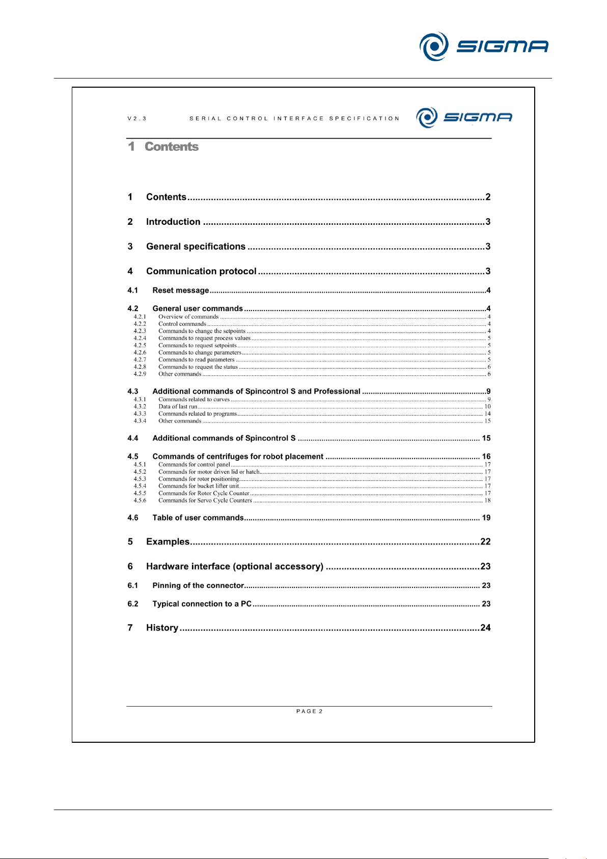
Refrigerated Centrifuge Sigma 8KS
Refrigerated Centrifuge Sigma 8KBS
11 Appendix
96 / 131
Version 08/2012, Rev. 2.5 of 02/07/2018 • sb
Translation of the original operating manual, part no. 0702502
Page 97
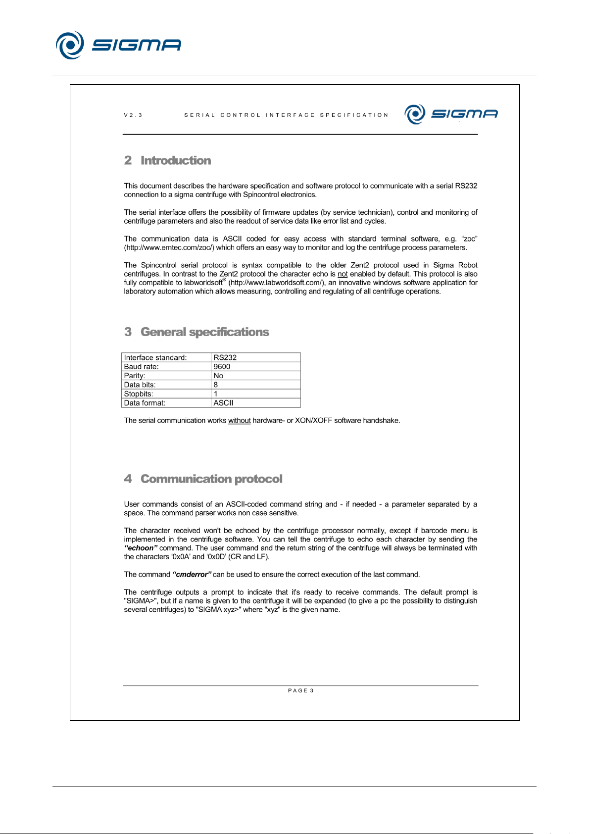
Refrigerated Centrifuge Sigma 8KS
Refrigerated Centrifuge Sigma 8KBS
11 Appendix
Version 08/2012, Rev. 2.5 of 02/07/2018 • sb
97 / 131
Translation of the original operating manual, part no. 0702502
Page 98
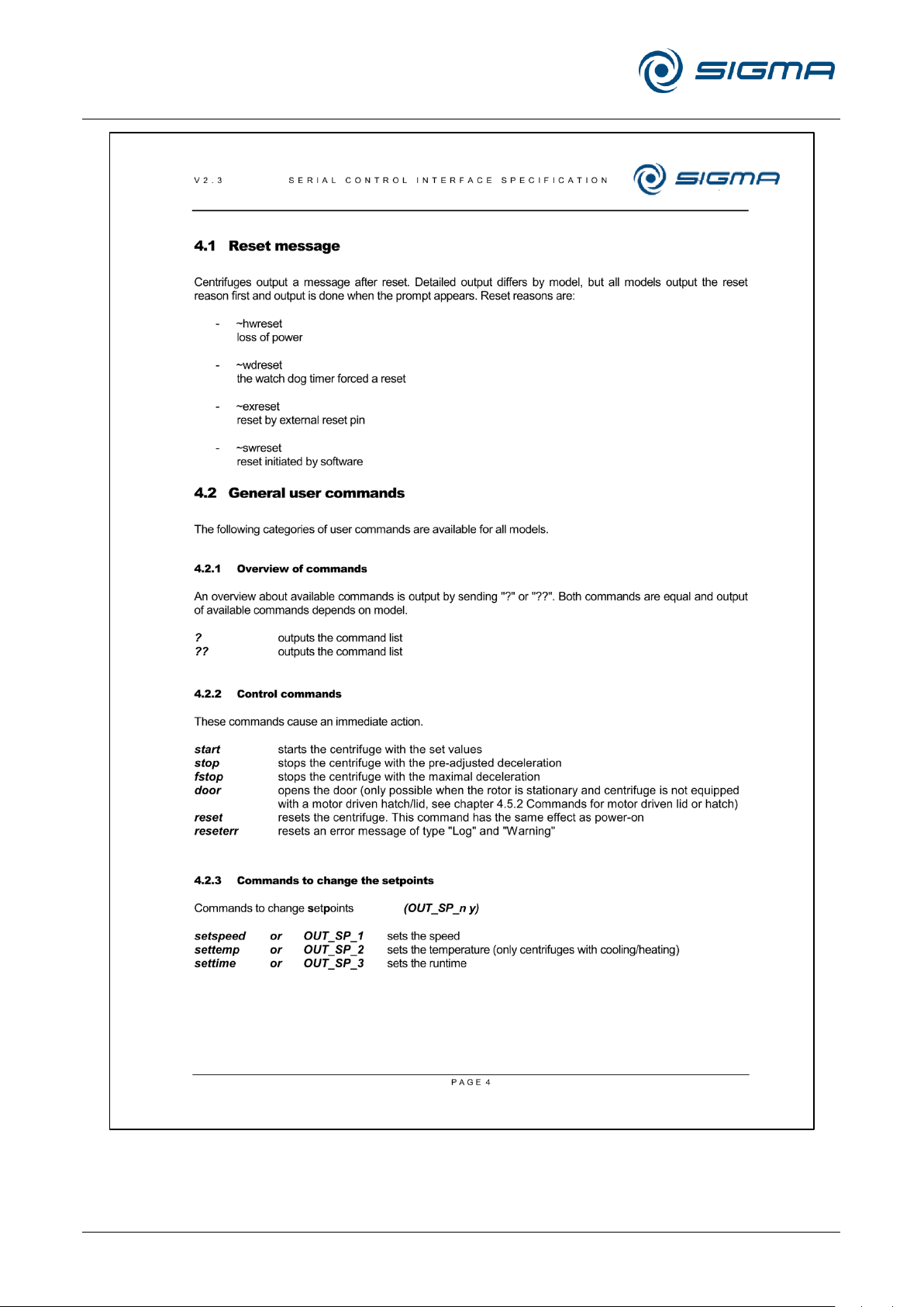
Refrigerated Centrifuge Sigma 8KS
Refrigerated Centrifuge Sigma 8KBS
11 Appendix
98 / 131
Version 08/2012, Rev. 2.5 of 02/07/2018 • sb
Translation of the original operating manual, part no. 0702502
Page 99
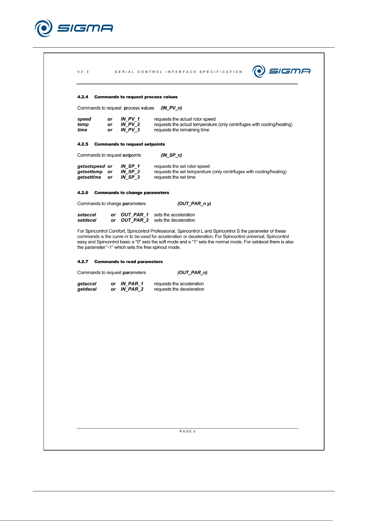
Refrigerated Centrifuge Sigma 8KS
Refrigerated Centrifuge Sigma 8KBS
11 Appendix
Version 08/2012, Rev. 2.5 of 02/07/2018 • sb
99 / 131
Translation of the original operating manual, part no. 0702502
Page 100
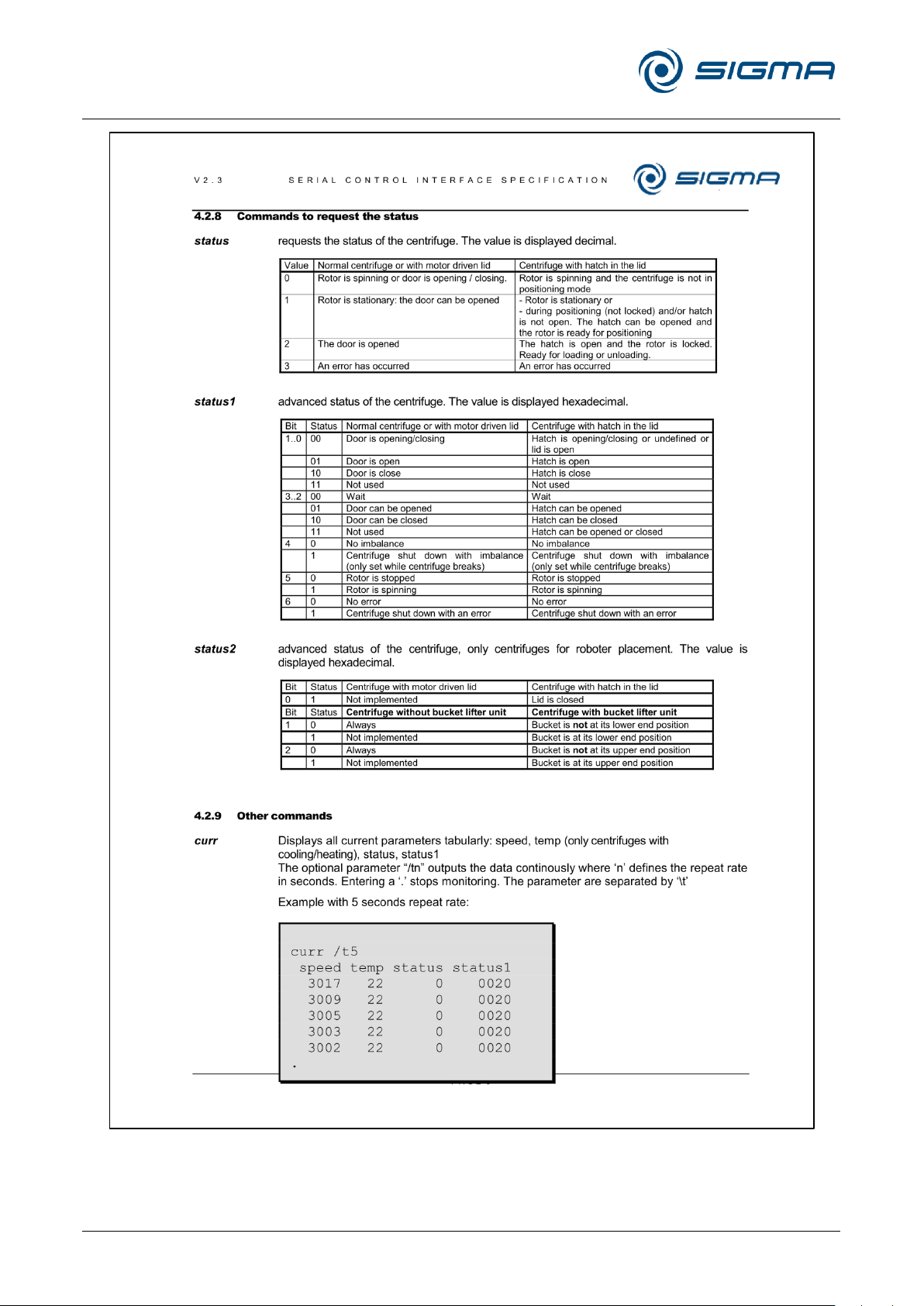
Refrigerated Centrifuge Sigma 8KS
Refrigerated Centrifuge Sigma 8KBS
11 Appendix
100 / 131
Version 08/2012, Rev. 2.5 of 02/07/2018 • sb
Translation of the original operating manual, part no. 0702502
 Loading...